- Assignments
- Preparing design for milling
- Modela MDX-20
- 3018
- Opinion
- Soldering
- Testing the boards
- Embroidered circuit
- Group assignment
- Files
Electronics Production


This week we’re finally starting with fabricating PCBs and programming them. I’ve worked with the Modela before and documented it here. My goal for this week is to learn how to use the 3018 CNC milling machine and how to make PCBs with the Cricut. I also want to make a circuit with an embroidery machine.
Assignments
| Progress | Task |
|---|---|
| Done | Group assignment: characterize the design rules for your in-house PCB production process: document feeds, speeds, plunge rate, depth of cut (traces and outline) and tooling. |
| Done | Document group assignment |
| Done | Individual assignment: make and test the development board that you designed to interact and communicate with an embedded microcontroller |
| Done | Documented how you made (mill, stuff, solder) the board |
| Done | Documented that your board is functional |
| Done | Explained any problems and how you fixed them |
| Done | Uploaded your source code |
| Done | Included a ‘hero shot’ of your board |
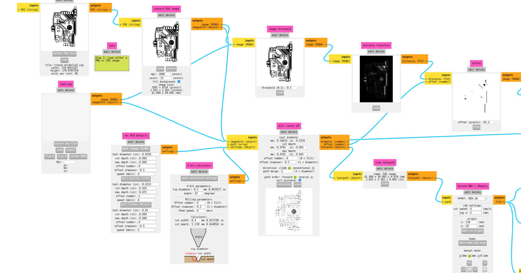
Preparing design for milling
When exporting from KiCad, the default is that the background is white and the traces are black. For mods, this has to be inverted.
I do this in Illustrator. One problem with Illustrator and SVGs is that when you edit your SVG, everything looks good, but then you save it and open it again suddenly traces are shifted when opening SVG again. Before closing the file everything looks fine:

Troubleshooting tries:
- SVG export with Preserve Illustrator Editing Capabilities checked and unchecked
- Pasting into another saved file to see if it was only with new files
- Changing decimal values (suggested here) to a higher value > this worked

When documenting I wanted to see if there was a better method to do this than this workaround in Illustrator. I found this video on using KiCad with mods, and noticed that the person in the video was inverting the SVG directly in mods. I didn’t try it for this week because I completely missed that option. I think I’ve tried it in the past and it didn’t invert properly, so I just assumed it wouldn’t work now. I tried it and it worked immediately. However, I think I will keep using Illustrator, because I still want to scale the bounding box around the board, and it’s annoying to do that in KiCad.
So: still using Illustrator to minimize the space around the board (to save copper), but inverting directly in mods.
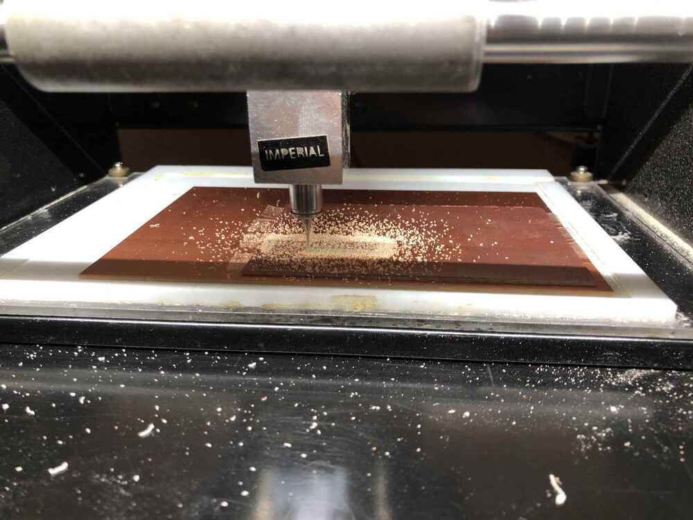
Modela MDX-20
Some general notes:
- White acrylic layer is surfaced so it is perpendicular to the machine
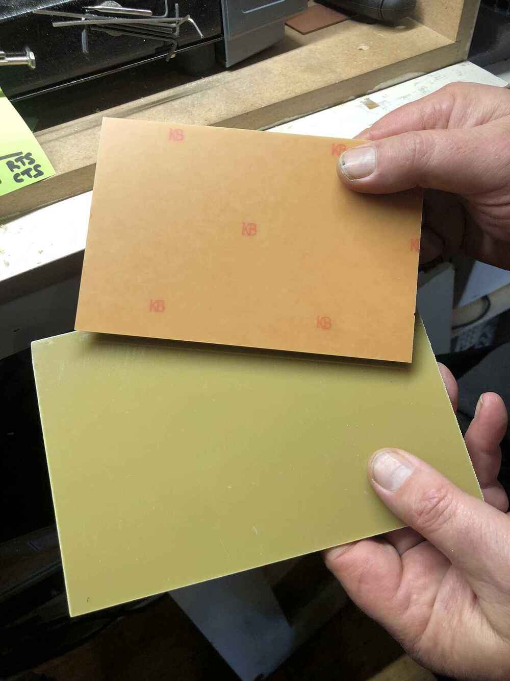
- We only mill with FR-1 which is pressed paper and epoxy. We don’t mill FR-4 because it is made of glass fibers and you don’t want to breathe glass in, and it also ruins the machine. Anything with a structure can’t be trusted, it may be glass, so only mill when you know it’s FR-1. FR-2 is a question mark, Henk doesn’t trust it.
- On the right you can see the back of the FR-1 and on the left FR-4:
- .006mm precision (in theory)
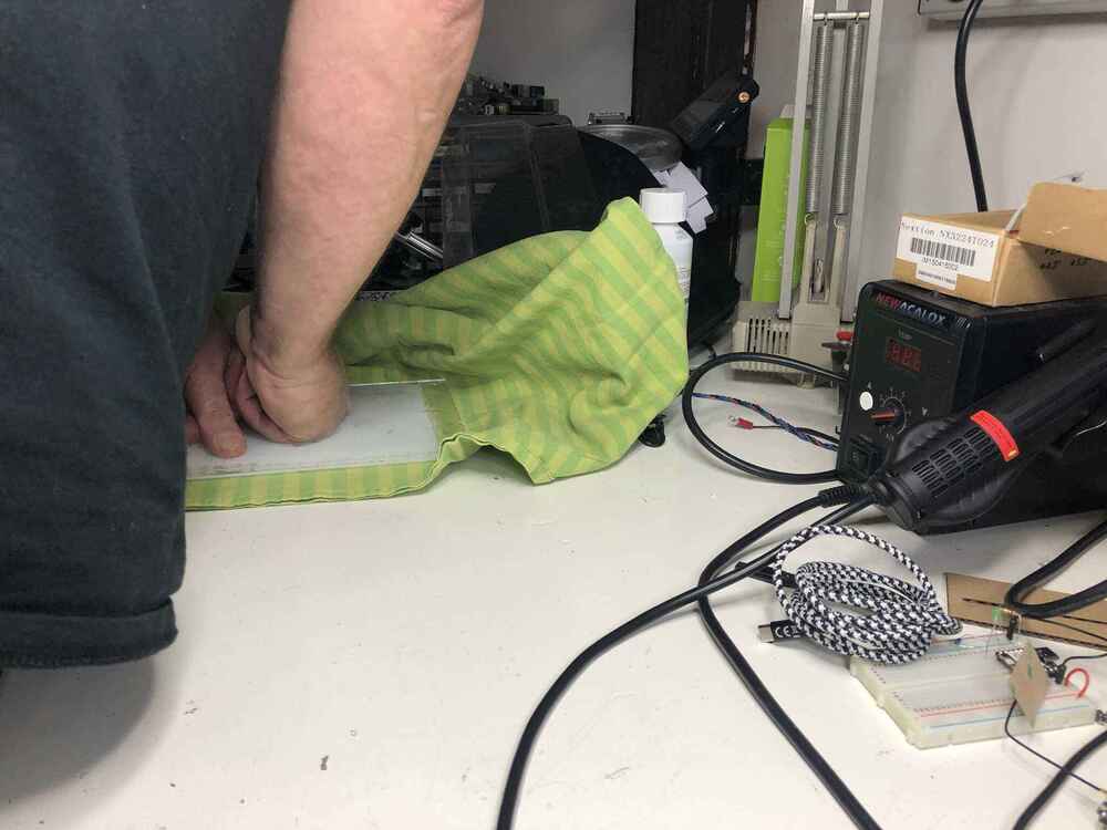
Before starting, Henk changed the sacrificial layer for us and measured if it is the same thickness everywhere; aligning it in one of the corners.
Replacing the copper plate
This has to be done periodically when there is no more space on the copper plate. Do not mill on the sacrificial layer. This is the sacrificial layer before cleaning, and Henk pushing the new sacrificial layer on top of the acrylic layer:

- Take off the previous copper plate (not the sacrificial layer) and clean with alcohol or sticker remover
- Tape copper plate to sacrificial layer. Make sure there is no overlap in tape and keep the jagged edges from the tape on the outside of the board. If possible, don’t stick it in the exact corner of the sacrificial layer because then it’s hard to get it off later
- Check if the copper plates are stuck on evenly with a caliper
- Attach it to the machine with the conic screws in the front. Make sure it’s tight but not extremely tight

Connecting mods to machine
- Turn on the machine; it opens in view mode. Click the view button on the machine to exit view mode. When you go out of view mode with the button, the spindle moves to its machine home (front left)
- You can use usb serial communication with Chrome only: other browsers don’t allow it (which is good and safe because it means that the browser has access to all usb connections). We don’t use it locally anymore; we run mods straight from the
- Web serial get device > scroll down > select
USB-Serial Controller D (ttyUSB0)> connect
- Check connection by moving the X and Y axes from mods
- Don’t move Z in mods
Loading file
- Open SVG in mods: first mill the traces, then the holes and cut-out
- Invert if not done manually (traces have to be white)
- Check whether the scale of the the board is correct. The size corresponds to the artboard size in Illustrator, so that’s how I check. When saved in Illustrator, the unit generally has to be set to 72. I change the dpi to 2000 for better resolution; any higher and mods crashes.
Changing the milling bit
We’re using two flute end mills: 0,4mm for the traces and 0,8mm or 1mm for the outline & holes. We have regular milling bits, conic bits and V-bits (V-bits are the blue ones).
- Conic milling bits: diameter of 0,25mm but we still call it 0,4mm (and use those settings in mods) because it goes down a little and then it becomes 0,4mm in practice. They are carbide titanium
- V-bits: width is a function of the depth; sensitive to the height. They are stronger and cheaper, but they are less precise in that sense Only change the milling bit with the marked grub screw
- Set origin X and Y in mods, making sure that your board fits. Remember the position or take a picture (it happens that you have to reset mods)
- Z has to be done manually on the machine. Hold your finger against the milling bit so it doesn’t fall out (they’re fragile). The milling bit should be up very high so you can move the spindle all the way down with the buttons on the machine.
- Then move it slightly up so you can level the milling bit on the material and so it can still move down (if it’s already at its deepest level, the machine can’t go lower to actually mill the material). Wiggle the milling bit a little to make sure it’s positioned flush on the material
- Tighten the grub screw snugly, not aggressively: otherwise you have to replace that screw a lot sooner

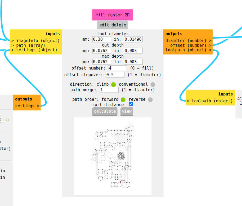
Settings in mods
I’m milling the development board for the Xiao boards that I’ve designed during electronics design week.
Traces
| Tool | Tool diameter | Cut depth | Max depth | Offset number | Offset stepover | Direction | Path merge | Path order | Cut speed (X, Y) | Jog Z |
|---|---|---|---|---|---|---|---|---|---|---|
| 0,4mm end mill or 0,25mm conic mill | 0,3962mm | 0,0025 to 0,004 inch | same as cut depth | 4 | 0,5 | Climb | 1 | forward | 4mm/s | 2 |
These are the settings I used:

I didn’t need the edge cut in this layer, so I changed my file and imported it again:
Outline
| Tool | Tool diameter | Cut depth | Max depth | Offset number | Offset stepover | Direction | Path merge | Path order | Cut speed (X, Y) | Jog Z |
|---|---|---|---|---|---|---|---|---|---|---|
| 0,8mm end mill | 0,79mm | 0,6096mm | 1,55mm (thickness of board so can vary) | 1 | 1 | Climb | 1 | forward | 4mm/s | 2 |

Here are the settings I used for the edge cut the first time. Notice how I didn’t change the units from 90 to 72.
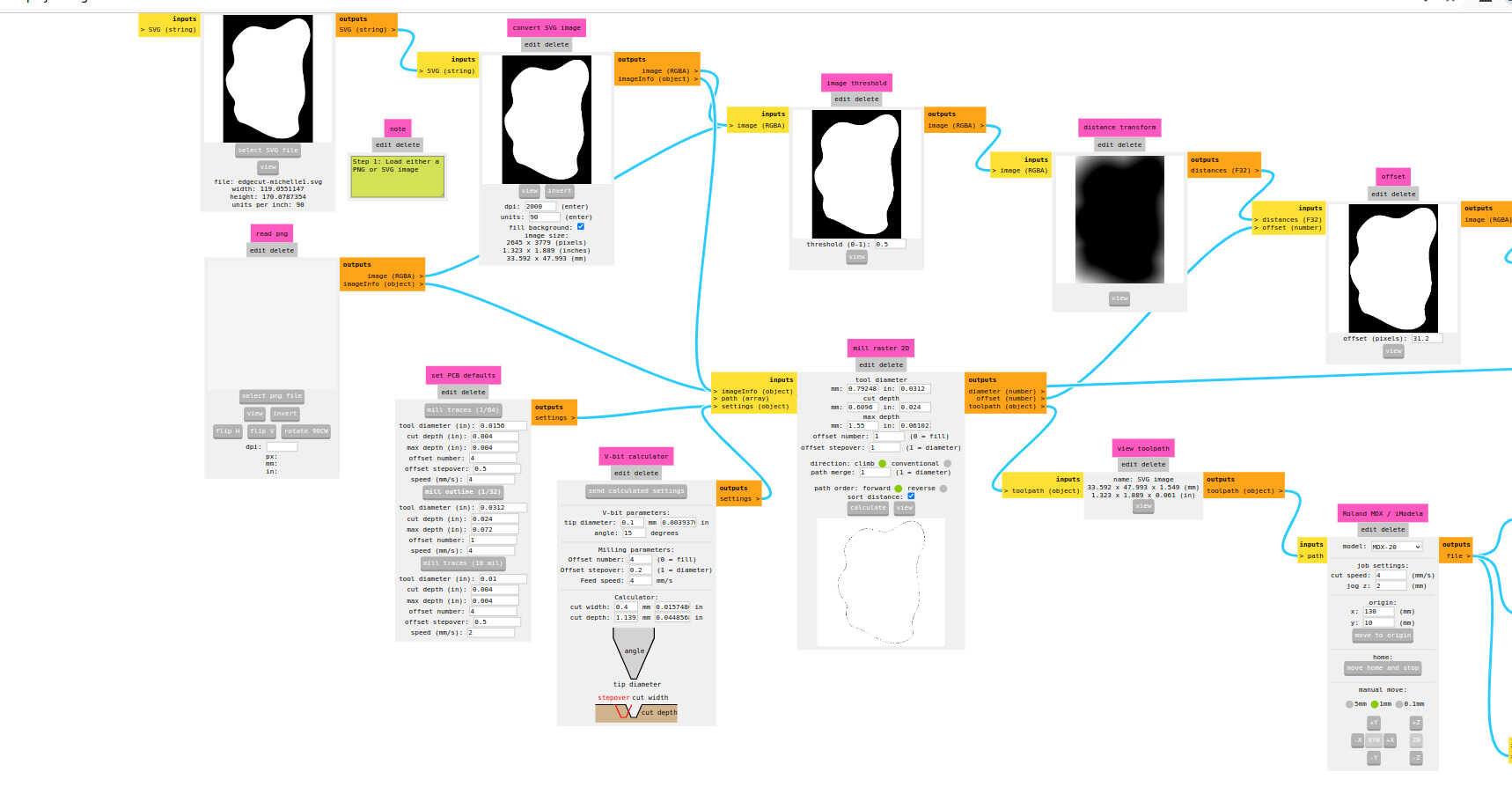
The second time I did do it right.

Milling
- Press calculate again, then send file. The machine should start milling immediately
- If it’s not going through you can loosen the screw in the front right slightly and tighten the one in the front left
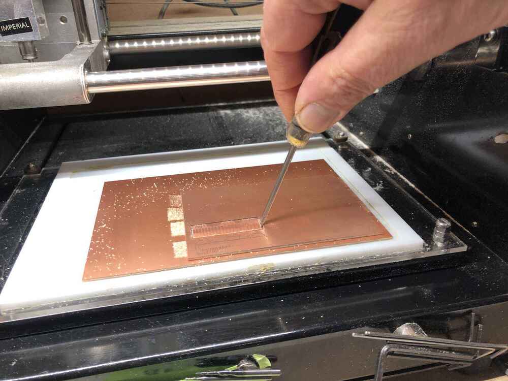
Traces and outline milled:


Use a screwdriver to take the PCB out carefully; first wiggle to see if the board is actually cut fully through, if not you can do the outline again.
Troubleshooting
To cancel in mods: reset by pressing up and down button on the machine, and refresh mods (you have to follow all of the steps above again) and wait until the light on the machine stops blinking. If you don’t refresh mods the light will just keep blinking and it will not reset.
What went wrong
DPI When forgetting to set the DPI from 90 to 72 I messed up the beautifully milled traces of my board, so I had to redo it.
Not properly checking toolpaths When I was in a hurry milling the APC board again, I didn’t notice that I still had one trace that was merged with a pad and not all of the holes were turned into toolpaths, so I had to drill some holes manually. I used a broken 0,4mm milling bit in a drill as a marker, then used a regular 0,8mm milling bit in a drill to make the holes. I broke a milling bit doing that, because I really shouldn’t have done that. I know I should know better so I was upset at myself for the rest of the day. I’m sorry Henk! I promise it won’t happen again.

Another thing that happened when I was milling the traces for the development board was that some of my traces fused together. I think I have to change my design rules in KiCad (even though they were the same as I have used before) to allow for slightly more space between the traces. I used 0,39mm as minimum clearance, but the milling bit in mods is set at slightly more than 0,39mm. One workaround in mods is to set the milling bit diameter to 0,38mm, so fooling mods to vectorize the file correctly.
In all cases I could have avoided the mistakes if I had paid a little more attention.
3018
We have a couple of 3018 Sainsmart CNC milling machines in the lab, that aren’t used a lot because everyone prefers the Modela. I’ve had one in the past that I’ve built but I’ve never used it (I sold it back to the lab). Time to change that.
- The 3018 has a grbl 1.1 board (for the operation of machines with XYZ axes).
- No end stops (so don’t test the limits) but it does have a Z probe
- Diameter 3,1mm shaft for the conic ones which is a standard measurement 1/8inch which is what we have now for the Modela and for the 3018 collet
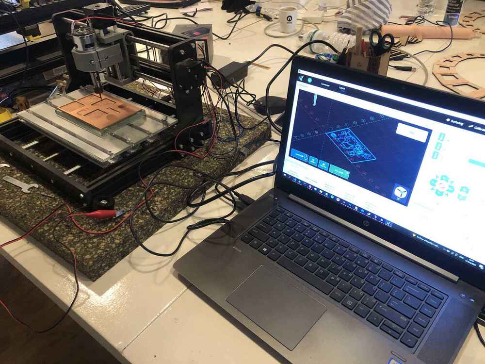
The set-up:
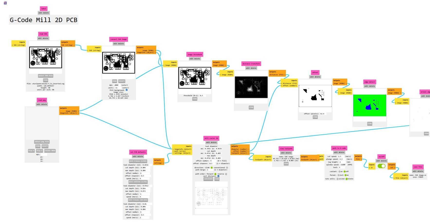
gcode
Generate the gcode (.nc files) with mods. You have to go to <modsproject.org> > right mouse click > programs > open program > G-code > mill 2D PCB

Settings are the same as for milling with the Modela, except for the cutting speed for all axes which is 2,5mm/s instead of 4mm/s. By default, the spindle speed is set to 11000 RPM. However the 3018 has a maximum of 10000 RPM so if you don’t change it, it will still be 10000 in reality.
| Tool: traces | Cut depth: traces | Tool: outline | Cut depth: outline | Cut speed (X, Y) |
|---|---|---|---|---|
| 0,25mm conic mill | 0,00325 inch | 0,8mm end mill | 1,55mm (0,6096mm per pass) | 2,5mm/s |
When you calculate it saves an nc file automatically.
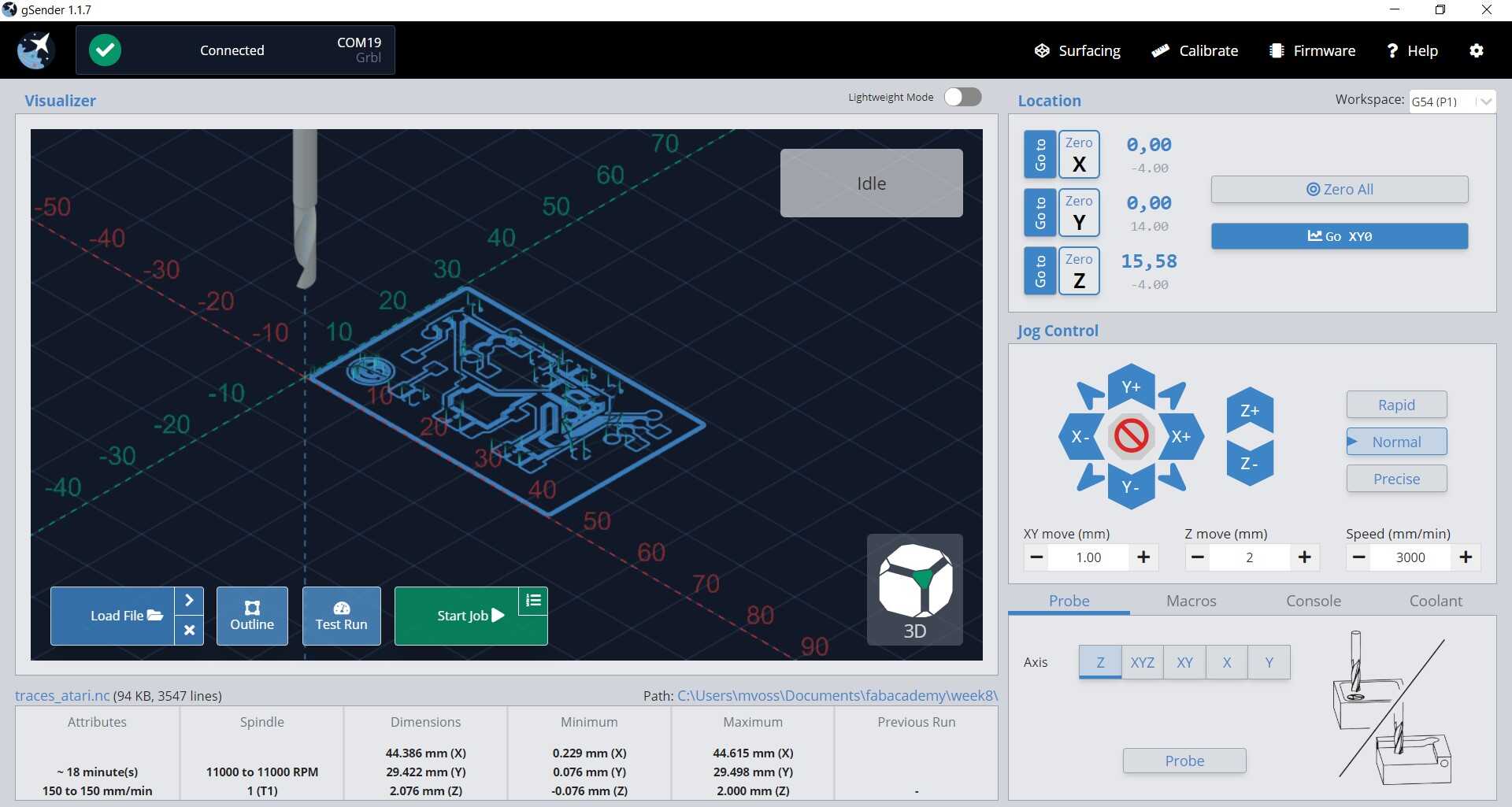
gSender
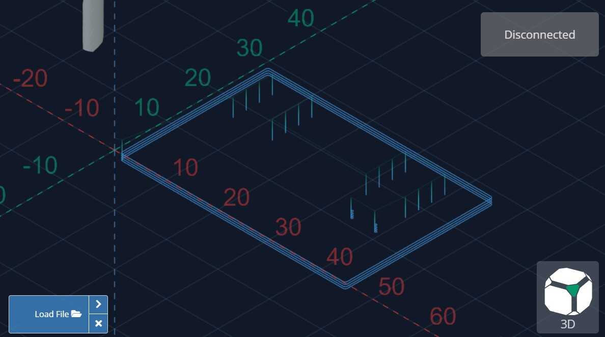
gSender is a really nice open source CNC control software that we use to operate the 3018. Download Gsender here.
Load the file for milling the traces with the Load File button. I forgot to remove the outside line so it milled that too but that’s fine.
Changing milling bit
This works a bit like on the shopbot, with a collet and nut. Use the two wrenches to loosen them and to replace the milling bit. Make sure you have the correct collet (for shafts of 1/8 inch).
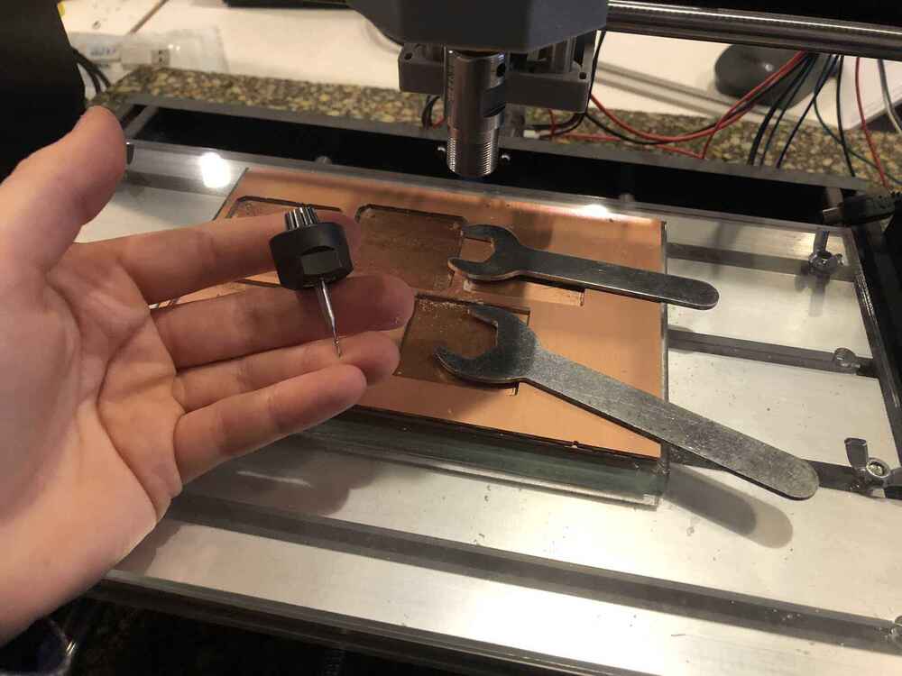
Zeroing
Move to the X,Y position where you want to start the file and press the Zero X and Zero Y buttons in the left top menu.
Zero Z with the metal Z Touch Probe. The official way to do this is by measuring the exact dimensions of the block, and filling that in in the software settings, then leveling on top of the metal block. The easier (and better) way to level, is to probe on the copper plate directly by setting the Z thickness to 0.
First select the Z Probe in settings, and set the Z thickness to 0. Make sure that Probe connectivity test is checked.
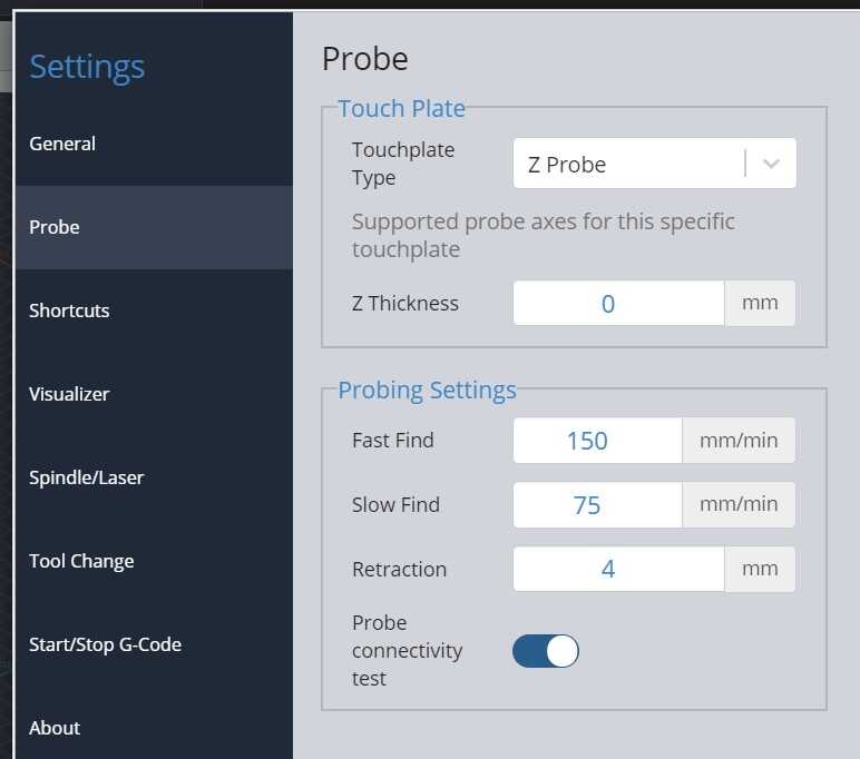
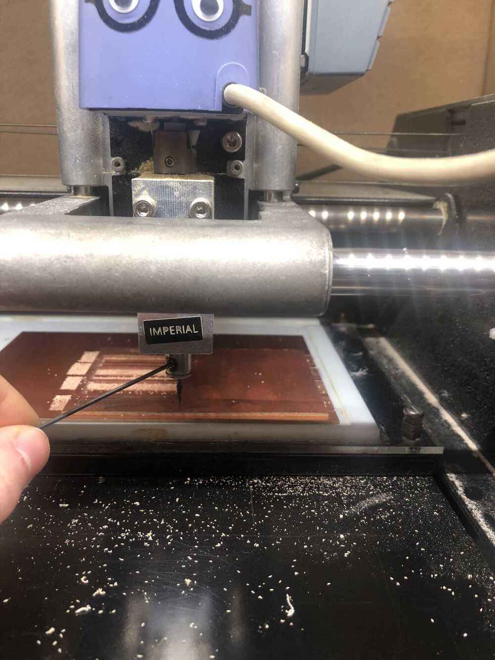
Clip the alligator clip to the milling bit and hold the metal block onto the copper plate: because the copper is conductive it will detect the metal plate there. Click Probe (Axis Z) in the bottom right menu. Before the software lets you continue, you have to hold the metal block to the milling bit to check the connection. the red circle turns green when a connection is detected.
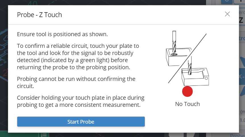
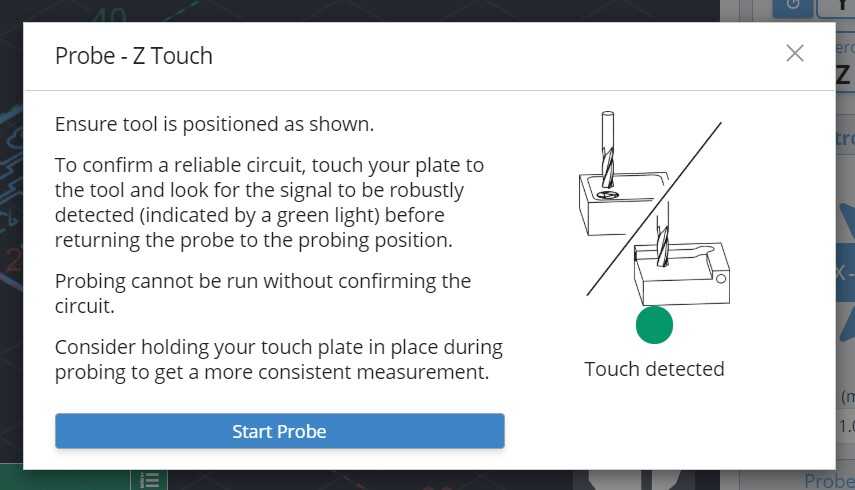
Now level the Z axis. Keep holding the the probe to the copper plate firmly until the machine is done leveling. Then remove the alligator clip! If the spindle starts spinning with the alligator clip attached, it’s going to be messy.
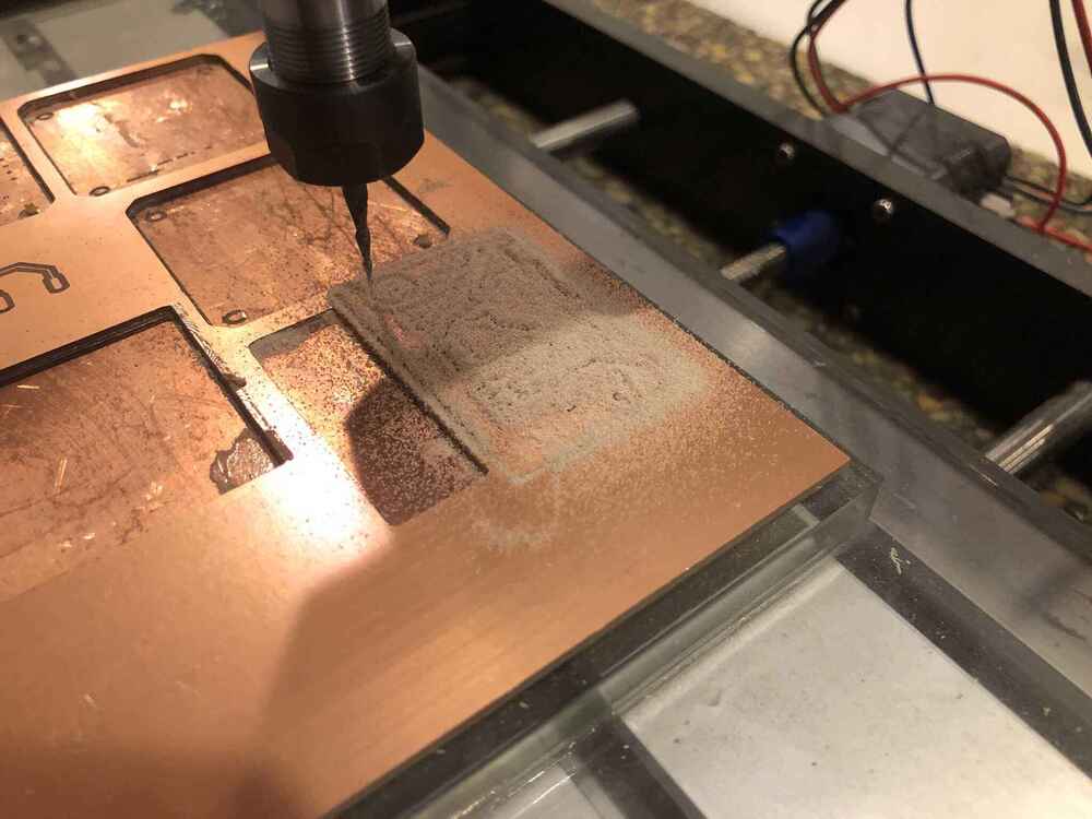
Milling
Then you can start the file. This machine has a plastic spindle assembly and it’s way more sensitive for vibrations, which you can hear when milling:
Milling the traces with the conic milling bit went fine:

When the traces are milled, load the holes & outline file, go to X,Y 0,0 again, replace the milling bit and zero Z again with the steps above.
It went wrong immediately and I broke the milling bit:

Usually the 0,8mm doesn’t break, so it surprised me. I went back to mods and changed the cut depth per pass to 0,4mm to be on the safe side. After that it went fine:

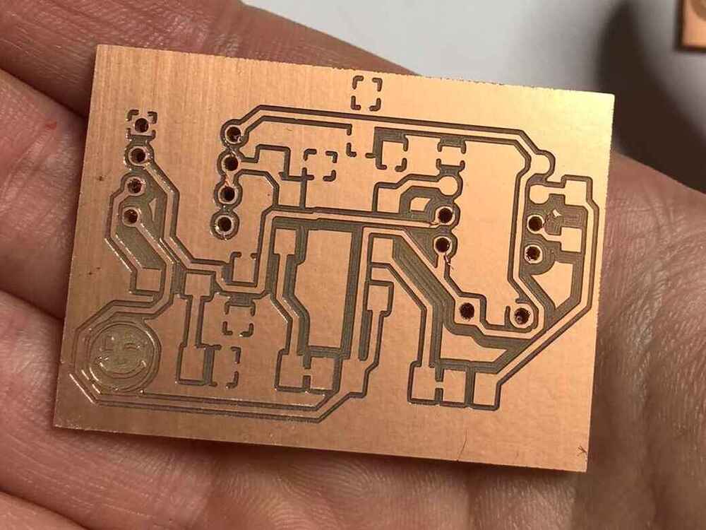
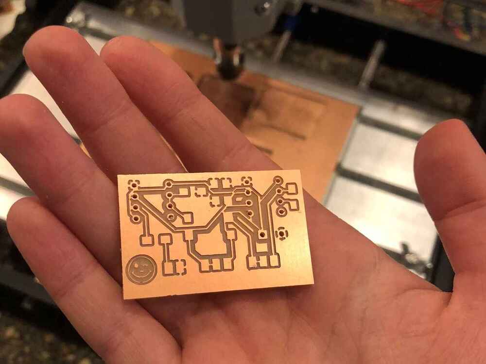
The board looks like it has been milled on a Modela worth thousands:
Opinion
I was already familiar with the Modela, so I knew I liked this machine. I have the steps and settings memorized, so it’s not too hard. However, I was rushing and not checking my files well enough because I assumed everything was fine. I can’t blame the machine for that.
I like working with the 3018 and gSender: it has a great interface and is easy in use. It’s nice to see the progress of the file. The downside is that it is less stable and the results are slightly worse than the Modela, but not by much. The price difference is huge, so I would say it’s definitely worth it.
Soldering
As mentioned before, when I wanted to start soldering I realized very soon that I had made mistakes. When I started soldering the APC I realized that some of my traces had merged as one. I already thought my clearances looked suspicious and when I compared my settings to the settings I documented, I realized something had gone wrong: instead of a 0,4mm clearance I had a 0,2mm clearance. This meant that some of my traces fused together. My track width was 0,25mm instead of 0,39mm. I double checked with the previous board and everything was fine there, so apparently the settings I used weren’t saved which I had assumed. I had to redo the routing of the wires in KiCad and mill the board again.
Then for the development board I did use the correct design rules, or so I thought. However when soldering this board I again discovered that I had some tracks that were fused together. This means that my design rules I had used are probably not good, because the minimum clearance I had used was too small. I have used it without trouble in the past, so I don’t know if I’ve been lucky, or if I changed something else accidentally. I’m going to change the clearance to 0,4mm. I’m thinking maybe it went well in the past because I used to work with PNGs instead of SVGs, but I haven’t compared it yet because I want to keep using SVG.
I tried to salvage both of them with some surgery, but it was in vain. I did both boards again on the Modela.


Development board
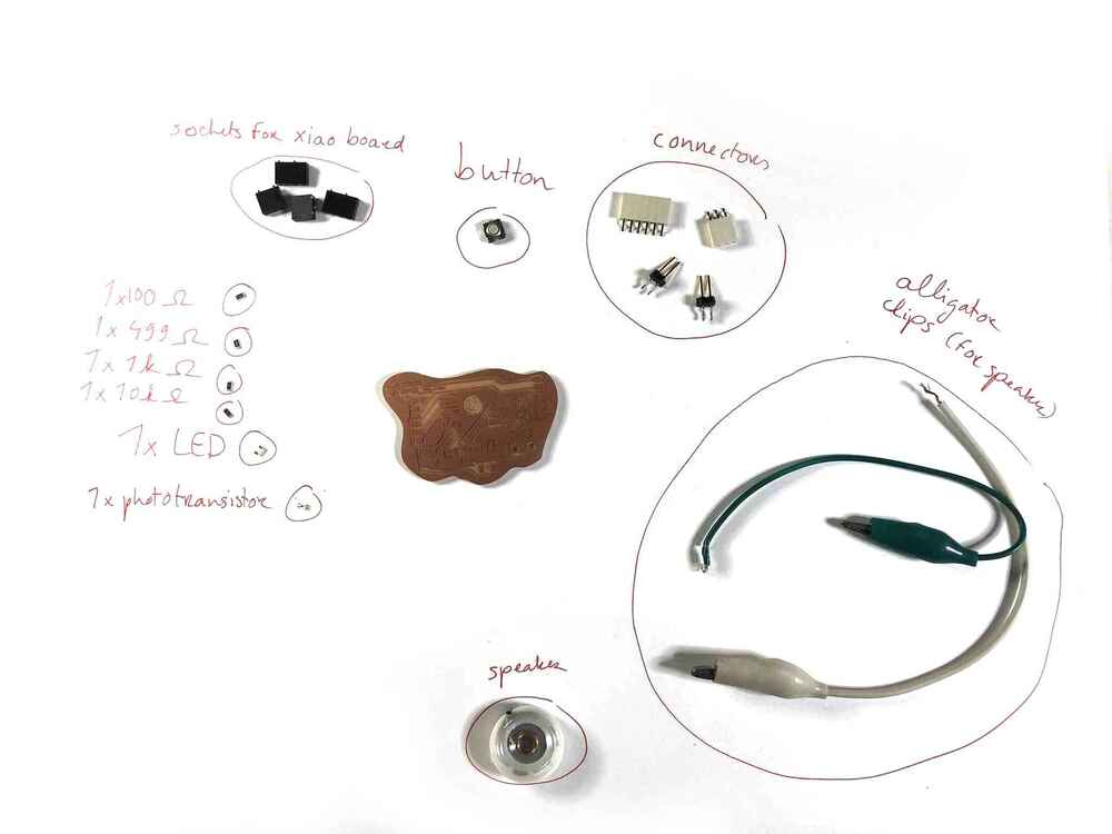
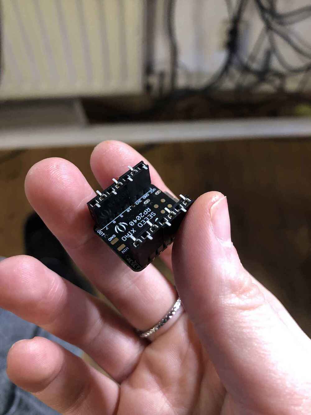
I started by gathering all of the components I needed for the board. The first time I started with the chip sockets, which was the last thing I should’ve soldered. When I redid the board I started with the smaller components. I used the same steps as below, first attaching the sockets to the chip to make sure everything would be perfectly aligned. Then securing the sockets in one corner with a little bit of solder. After that first soldering all of the other outside legs, then removing the chip and soldering on the inside of the sockets as well.
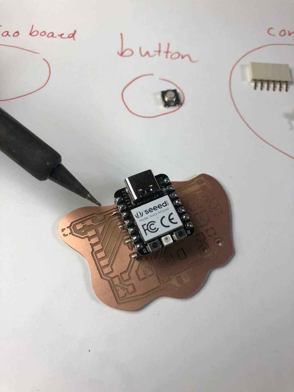

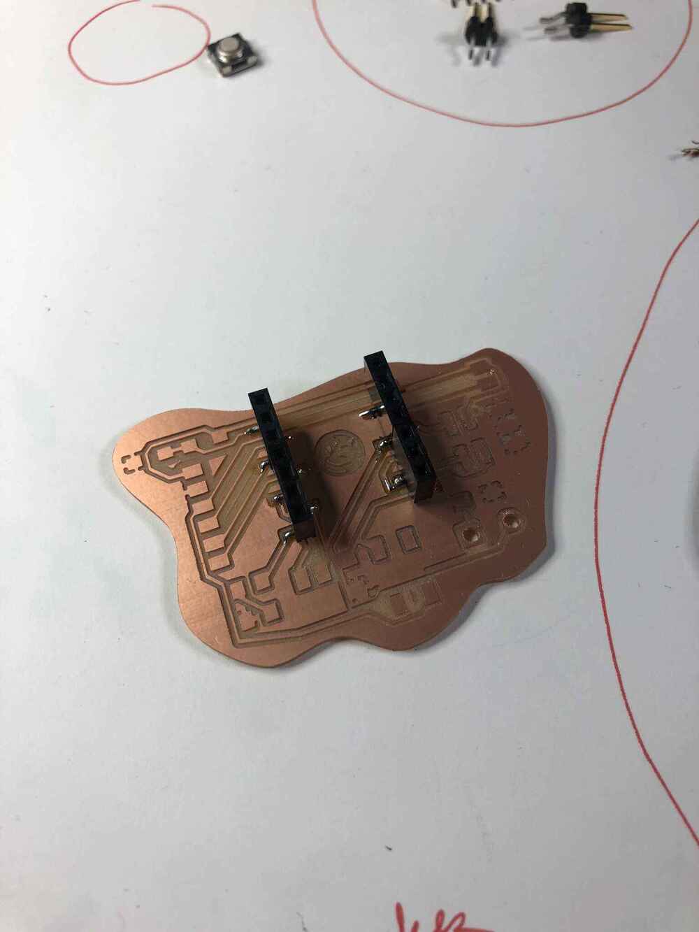
It’s not my best solder work, but it’s fine:

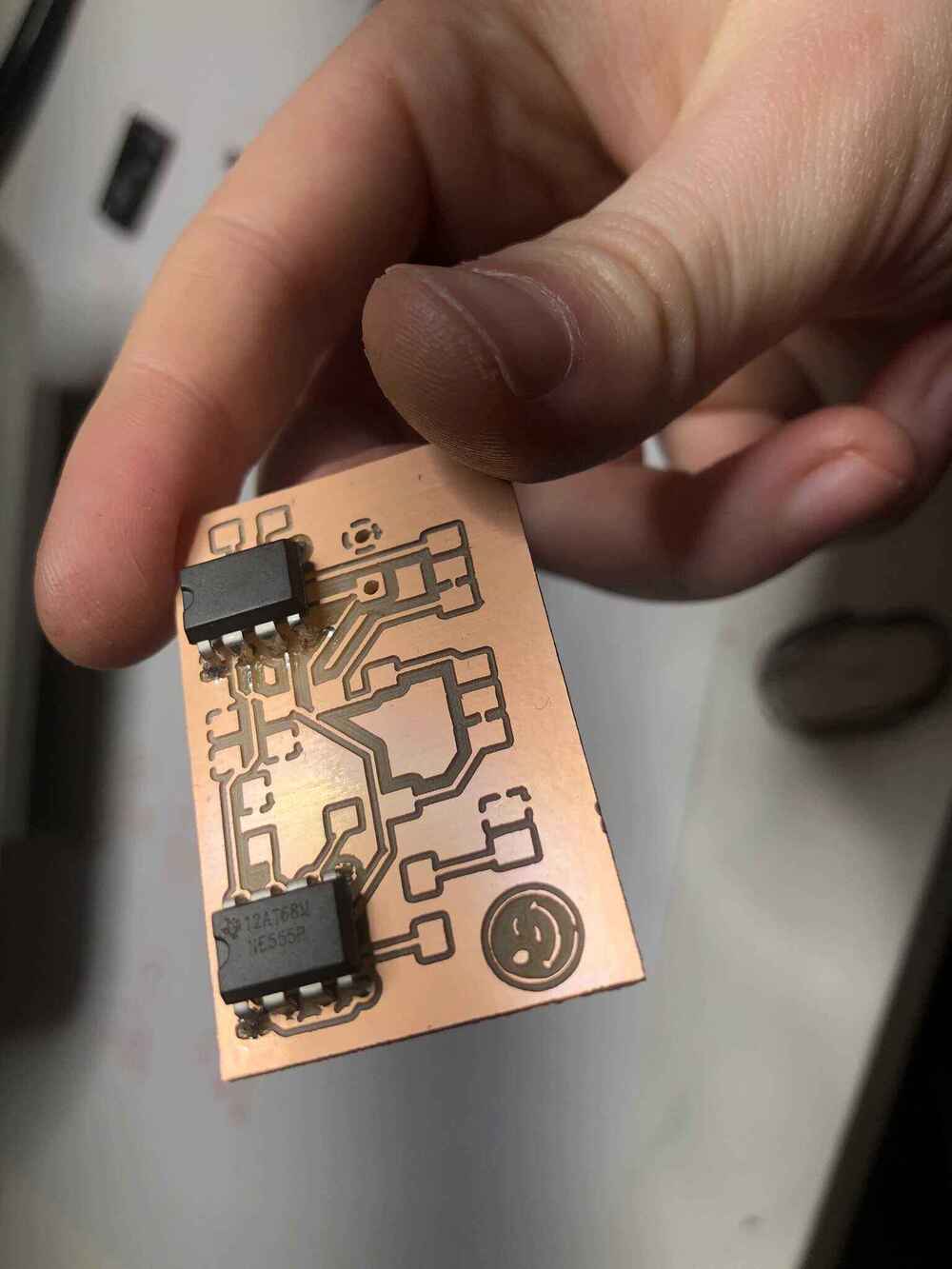
APC

This board was my extra KiCad design test, and since it’s an analog synthesizer it doesn’t have to be programmed. It doesn’t count for this week’s programming part of the assignment. I made it because I really wanted to make it.
When I finished soldering the 555 chips, I realized that a lot of traces were merged, and I redid the entire design of the board.
Results
Both finished boards:
Testing the boards
Development board
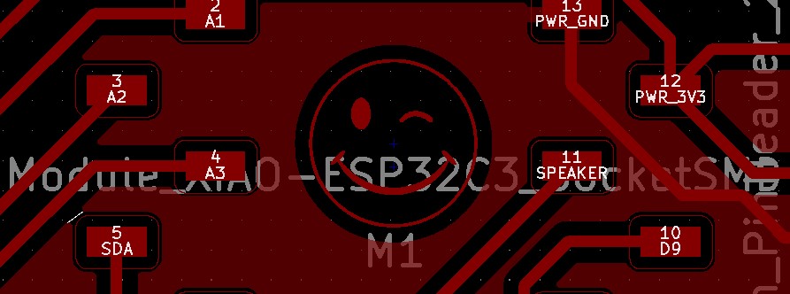
I tried a Blink sketch with the ESP32C3 in the socket. It uploaded without problem, but the LED didn’t blink. My first mistake was that I didn’t refer to the correct pin. But when I corrected it, it still didn’t work. After further inspection of my board, I realized that I had two islands of ground that were not connected at all. I went back to the KiCad sketch, and I after closer inspection, I could see a tiny white line between the two ground areas that I had missed. It was even visible in the header image for the electronics design week, under the d on the left:
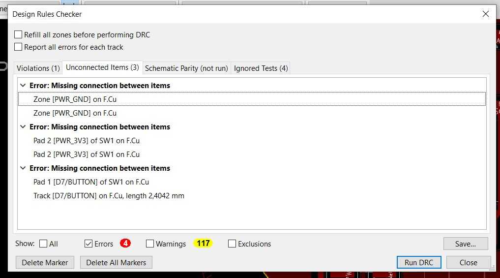
As a result I learned about the design rules checker this week. The warnings I could ignore, and some of the errors as well (such as the button pads not being connected: it doesn’t matter because they are internally connected), but it also told me about the ground areas not being connected.
I solved it with a 0 Ohm resistor bridge.
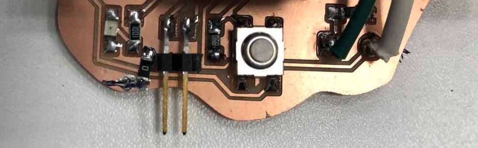
After that, my Blink sketch worked. I then tested the button with Adrians code here and that worked as expected too.
To try out the speaker, I integrated the toneMelody into my code, so the example melody would start playing when pressing the button.
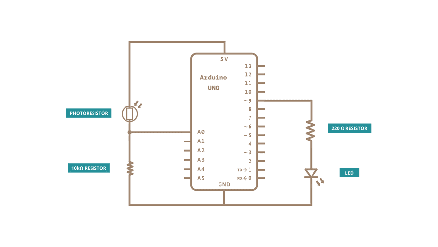
For the phototransistor, I integrated Adrians code for his phototransistor module into my code. The readings I got were not what they should be, so something is wrong. I kept getting the same value in the serial monitor. Henk suggested I looked at Nadiehs documentation. It would be possible that I grabbed the IR phototransistor by accident, but then I would still expect there to be some fluctuation in the measurements. I used the multimeter to check the voltage passing through, and it was a constant 5V. I also shorted the circuit twice and the chip shut off, but plugging it back in worked. I then checked Adrians documentation again and saw that he connected it to the 3.3V so I did some rerouting with a wire to try that out, but it still gave me the same result. I was then thinking that maybe I soldered it the wrong way around so I checked the datasheet and soldered on a new one, but it also gave me the same 4095.
![]()
https://www.reddit.com/r/esp32/comments/hlnn30/esp32_analogread_values_incorrect_only_get_0_or/
Code
// Fab Academy 2023 - Fab Lab León
// Button + LED
// Fab-Xiao
// Modified by Michelle Vossen 22/3/23
//
// Original code:Neil Gershenfeld 12/8/19
// This work may be reproduced, modified, distributed,
// performed, and displayed for any purpose, but must
// acknowledge this project. Copyright is retained and
// must be preserved. The work is provided as is; no
// warranty is provided, and users accept all liability.

#include "pitches.h"

const int ledPin1 = D6;     // first light  RP2040 pin 0 or ESP32-C3 pin D6
const int buttonPin = D7;   // button pin  RP2040 pin 1 or ESP32-C3 pin D7
const int speakerPin = D10; // pin where the speaker is attached
const int sensorPin = A0;   // analog input pin RP2040 pin 26 or ESP32-C3 pin A0
int sensorValue = 0;        // variable to store the value coming from the sensor
int buttonState = 0;        // initial state of the button
int i = 0;                  // variable intensity led

// notes in the melody:
int melody[] = {
  NOTE_C4, NOTE_G3, NOTE_G3, NOTE_A3, NOTE_G3, 0, NOTE_B3, NOTE_C4
};

// note durations: 4 = quarter note, 8 = eighth note, etc.:
int noteDurations[] = {
  4, 8, 8, 4, 4, 4, 4, 4
};

void setup() { //declaration of inputs and outputs
  Serial.begin(115200); // initialize serial communications
  while (!Serial) {
    ; // wait for serial port to connect. Needed for native USB port only
  }
  pinMode(ledPin1, OUTPUT);
  pinMode(buttonPin, INPUT);
}
void loop() {
  buttonState = digitalRead(buttonPin);// we read the state of the button
  sensorValue = analogRead(sensorPin); // read the value from the sensor
  Serial.println(sensorValue); // print value to Serial Monitor
  delay(50); // short delay so we can actually see the numbers
  if (buttonState == HIGH) { //if we press the button
    digitalWrite(ledPin1, HIGH);
    for (int thisNote = 0; thisNote < 8; thisNote++) {

      // to calculate the note duration, take one second
      // divided by the note type.
      //e.g. quarter note = 1000 / 4, eighth note = 1000/8, etc.
      int noteDuration = 1000 / noteDurations[thisNote];
      tone(speakerPin, melody[thisNote], noteDuration);

      // to distinguish the notes, set a minimum time between them.
      // the note's duration + 30% seems to work well:
      int pauseBetweenNotes = noteDuration * 1.30;
      delay(pauseBetweenNotes);
      // stop the tone playing:
      noTone(speakerPin);
    }

  }
  else {  //if we don't press the button
    digitalWrite(ledPin1, LOW);
  }
}
APC
I tried it out, but the volume was very low on the speaker and one of the potentiometers didn’t work. One of the 555 chips also got really hot, so I probably have a short somewhere.
Update: during input devices I learned about rotary encoders. The potentiometer that didn’t work is a rotary encoder.
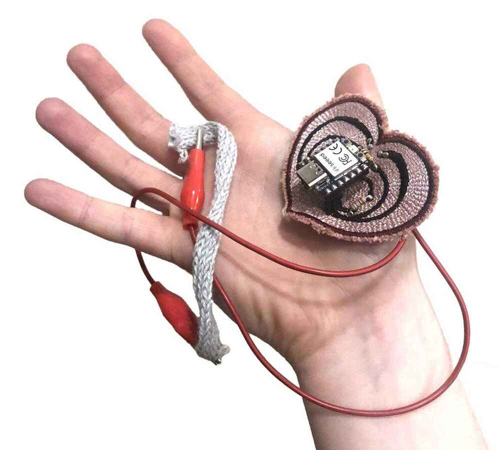
Embroidered circuit
I also wanted to make something to map the value from e-textiles samples to another output, such as an LED or a sound. I’ve made circuits like this before using this resistance value measurement tutorial combined with a map function. The circuit was made with a buch of alligator clips and whatever Arduino I had lying around. I wanted to make something a bit more stable, so I wanted to make a specific circuit for it. On Monday I was at my other job in the HKU textile workshop, where there are two embroidery machines. I drew up a circuit to embroider:
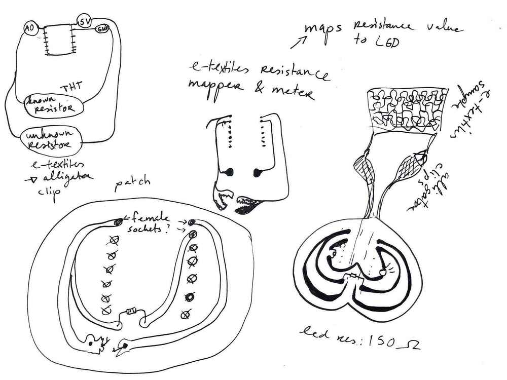
The circuit kind of requires you to test beforehand with a multimeter what the range is, then swap the known resistor accordingly. You also have to change the resistor when the resistance range of the sample is very different. This is very inconvenient. When I finished drawing the circuit, I remembered something about calibration. I found this explanation and circuit.
I’m very lucky, because it is exactly the same circuit as I had drawn.
Board design
I cleaned up the drawing of the heart-shaped circuit in Photoshop, then traced it in Illustrator; then I simplified the paths so it would be more smooth. I used the pads from KiCad SVG exports as a reference to position the XIAO board correctly. I’m only using four pins on the board (GND, 5V, D0, D1). I eyeballed the other distances.


I used a symmetric heart shape as the background: it’s going to be an embroidered patch. Then I exported it as a WMF because that is the file type we use to import vector images into the embroidery software PE Design.

PE Design
I imported the design as a vector image (WMF), and applied different stitches to the traces, background and outline. I used a satin stitch for the traces and outline, and a spiral stitch for the background. I also made two variants as back-up, without a background stitch. Then I exported it as a DST file, the file format used for Tajima machines and our own Vortex machine.

Vortex embroidery machine
This the beautiful embroidery machine in the textile workshop. It’s my favorite machine.

The fabric has to be secured into the embroidery frame with the screw at the top. You always need some sort of backing material to get a nice and stable result. I used some leftover fabric and a cotton soft backing material that you can rip off easily later.
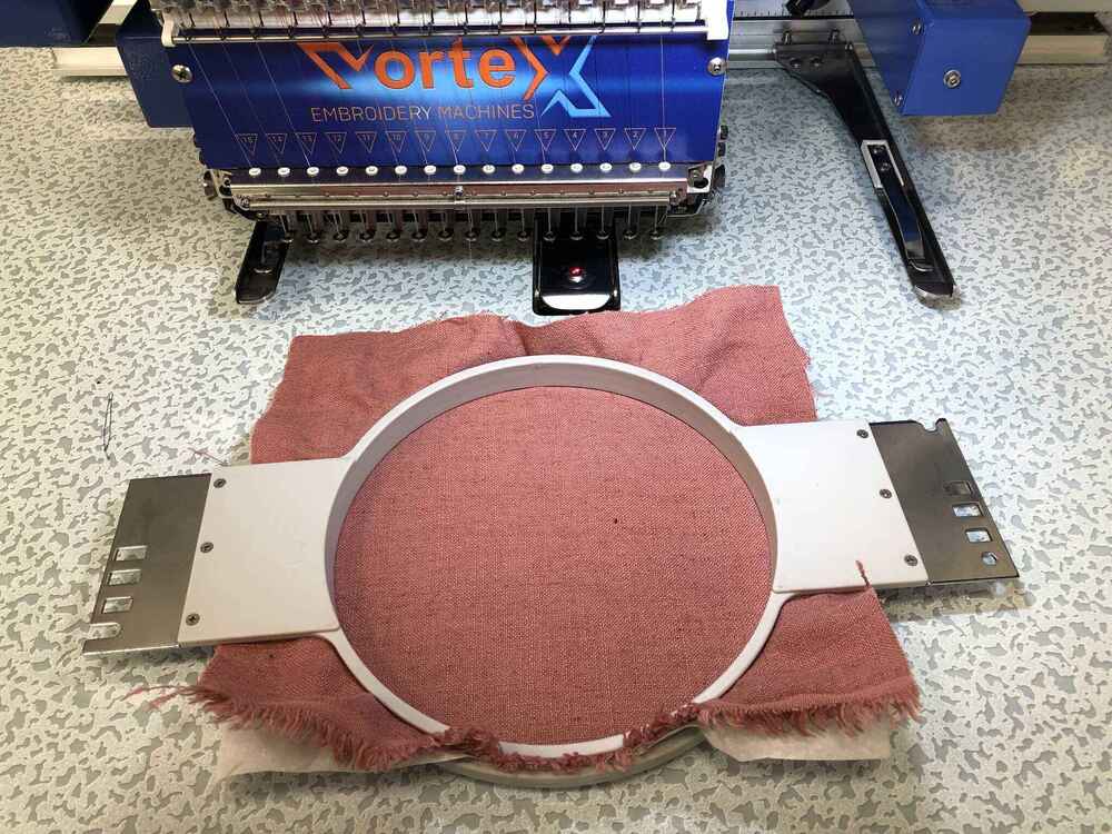
Then I got started with the embroidery. I loaded the file, picked the colors I wanted and set up the machine. The conductive yarn has to go in the bobbin case, so I paused the machine before it got started on the traces. Because the conductive yarn is much thicker, the screw on the bobbin case had to be loosened. The yarn has to be lightly tensioned by the metal plate holding it in place.

When embroidering the traces, I lowered the speed of the machine to its lowest setting which is 400 stitches per minute (top speed is 1200). I was pretty surprised that it went very well; I’ve tried it with conductive yarn and sometimes the machine struggles with it.
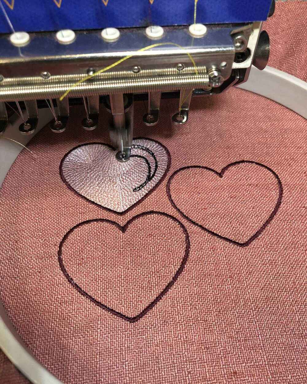
At this point I stopped the machine because I didn’t have enough yarn left on the bobbin.

It looks pretty good in the front and on the back; I will have to do some trimming of the conductive thread to make sure I don’t get any short circuits.


Rivets
The next day in the lab I had to make the circuit. Since you can’t solder onto most conductive yarn and this thread is no exception, I had to find a way to make easy solderable connections. The alternative was embroidering the components in place by hand in the back, and I’m not a fan of that because it takes long, the connections are very unstable and it looks pretty ugly. I found in the comments here that people used crimp beads to solder onto, but Henk suggested using rivets since we have a spindle and rivet tools. I used these tiny rivets with a diameter of 1mm (although they are still the biggest rivets in the lab). With this diameter I can still put the legs of THT components through.


All of the rivets inserted:
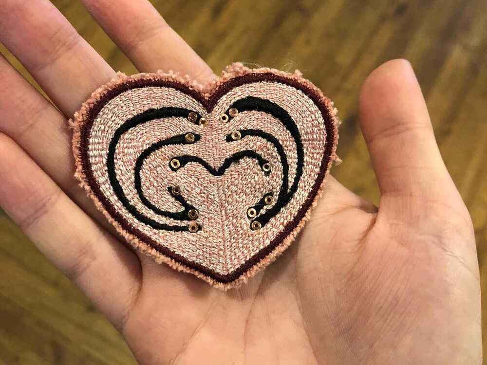
Soldering
I’m using the XIAO RP2040, and instead of a red LED with a 150 Ohm resistor, I’m using a white LED with a 68 Ohm resistor.
Soldering the parts to the rivets was pretty easy. It took more time to figure out where the short was in the bottom left of the circuit. After a lot of trimming of the threads I managed to fix the short circuit.
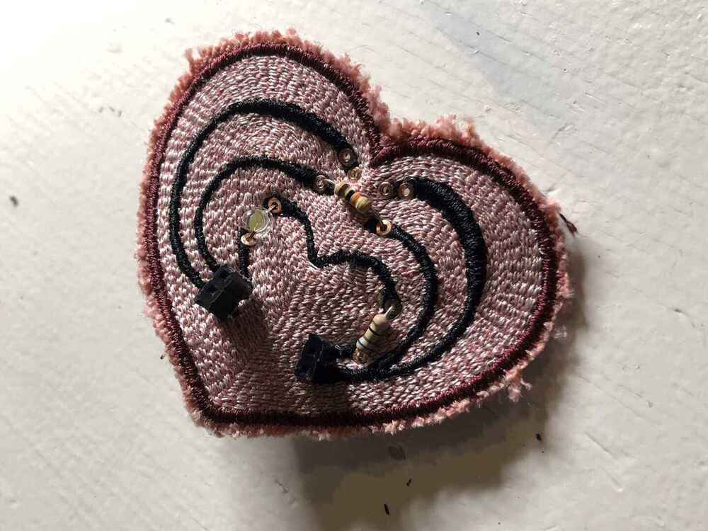


Action shots:


Testing the board
I started out with a blink sketch to test if the LED was working. At first it didn’t work, leaving me worried that I somehow still shorted my circuit or fried the LED in the process. I tested it with a multimeter and the LED was fine, and measured the circuit again for anything strange. Everything seemed fine, so I looked at the pin-out again to see if I wasn’t using the correct pin in my code. Then I realized I had attached the XIAO board upside down, so it makes sense that it doesn’t work. After that the LED started blinking immediately.
Now it was time for the actual purpose of this board: becoming an e-textile swatch tester & variable resistance visualizer. I attached a knitted stretch sensor from the textilelab, stretched and released the sample during the 5 second calibration window (indicated by the on-board LED) to get its value range, then watched as the LED responded to the stretching of the sample:
Final board:
Code
This is the code that I modified to work for this e-textiles tester.
/*
  Calibration

  Demonstrates one technique for calibrating sensor input. The sensor readings
  during the first five seconds of the sketch execution define the minimum and
  maximum of expected values attached to the sensor pin.

  The sensor minimum and maximum initial values may seem backwards. Initially,
  you set the minimum high and listen for anything lower, saving it as the new
  minimum. Likewise, you set the maximum low and listen for anything higher as
  the new maximum.

  The circuit:
  - analog sensor (potentiometer will do) attached to analog input 0
  - LED attached from digital pin 9 to ground through 220 ohm resistor

  created 29 Oct 2008
  by David A Mellis
  modified 30 Aug 2011
  by Tom Igoe
  modified 07 Apr 2017
  by Zachary J. Fields
  modified 21 Mar 2023
  by Michelle Vossen

  This example code is in the public domain.

  https://www.arduino.cc/en/Tutorial/BuiltInExamples/Calibration
*/

// These constants won't change:
const int sensorPin = D0;  // pin that the sensor is attached to
const int ledPin = D1;      // pin that the LED is attached to
const int calPin = 25;      // on-board LED on the RP2040

int sensorValue = 0;   // the sensor value
int sensorMin = 1023;  // minimum sensor value
int sensorMax = 0;     // maximum sensor value


void setup() {
  // turn on LED to signal the start of the calibration period:
  Serial.begin(9600);
  while (!Serial) {
    ; // wait for serial port to connect. Needed for native USB port only
  }
  pinMode(calPin, OUTPUT);
  digitalWrite(calPin, HIGH);

  // calibrate during the first five seconds
  while (millis() < 5000) {
    sensorValue = analogRead(sensorPin);

    // record the maximum sensor value
    if (sensorValue > sensorMax) {
      sensorMax = sensorValue;
    }

    // record the minimum sensor value
    if (sensorValue < sensorMin) {
      sensorMin = sensorValue;
    }
  }

  // signal the end of the calibration period
  digitalWrite(calPin, LOW);
}

void loop() {
  // read the sensor:
  sensorValue = analogRead(sensorPin);
  Serial.println(sensorValue);
  // in case the sensor value is outside the range seen during calibration
  sensorValue = constrain(sensorValue, sensorMin, sensorMax);

  // apply the calibration to the sensor reading
  sensorValue = map(sensorValue, sensorMin, sensorMax, 0, 255);

  // fade the LED using the calibrated value:
  analogWrite(ledPin, sensorValue);
}
Reflection
I should have used pins that has a little more distance between them (not possible for the power and ground though), because it would have saved me a lot of time. Making the traces a little smaller also would have helped. I’m still pretty happy with this board and learning about calibration, because my previous method of making e-textiles instruments was cumbersome. This is also the most stable e-textiles circuit I’ve ever made. The only issue currently is that sometimes you have to move the patch around a little so the LED is connected. I think the problem is in the embroidery stitches and not in the soldering. I could possibly fix it with some extra conductive yarn.
Group assignment
For the group assignment we have to characterize the design rules for our in-house PCB production processes. Henk showed us the Modela and the 3018 Sainsmart CNC, so that’s what we are focussing on and comparing.
To create the toolpaths for PCBs, we are using mods. The mods CE project (community edition) is a project maintained by the fab community (mostly Fran now). From the gitlab:
mods CE (community edition) is a fork of CBA mods research project. mods is a modular cross platform tool for fablabs. It is based on independent but interrelated modules. mods could potentially be used for CAD, CAM, machine control, automation, building UI, read input devices, react to to physical models, and much more. The possibilies are endless. The goal of the community edition is to provide documentation, support and help the community engage in the project and foster the development/exchange of new modules.
The file that we are using to compare is the CAM trace width provided by Neil.
Settings
Many settings that we are comparing have default settings that have been determined by the people in the lab over the years. This means that faster usually means broken milling bits, and slower just isn’t necessary. The same principle goes for cut depth: it has been determined that with a cut depth of 0,0025-0,004 inch you generally cut through the copper, which is the goal. Any deeper doesn’t make sense. the depth of cut for the edge cut and holes are determined by the thickness of the copper plate used.
Here are the settings we used and our observations.
| Machine | Tool: traces | Cut depth: traces | Tool: outline | Cut depth: outline | Cut speed (X, Y) | Plunge speed (Z) | Spindle speed | Remarks |
|---|---|---|---|---|---|---|---|---|
| Modela MDX-20 | 0,4mm end mill | 0,004 inch | 0,8mm end mill | 1,55mm (0,6096mm per pass) | 4mm/s | not shown in mods | not shown in mods | First time not close enough to the bed so didn’t cut through. Second time it did. Cut depth of the traces could be less |
| Modela MDX-20 | 0,4mm end mill | 0,00325 inch | 0,8mm end mill | 1,55mm (0,6096mm per pass) | 4mm/s | not shown in mods | not shown in mods | Smoother result for the traces than the previous test |
| Modela MDX-20 | 0,25mm conic mill | 0,00325 inch | 0,8mm end mill | 1,55mm (0,6096mm per pass) | 4mm/s | not shown in mods | not shown in mods | Barely any difference noticeable, which makes this milling bit a better choice because it is cheaper and stronger |
| 3018 | 0,25mm conic mill | 0,00325 inch | 0,8mm end mill | 1,55mm (0,6096mm per pass) | 2,5mm/s | 2,5mm/s | 11000 RPM (according to Henk the max is 10000 RPM for this machine) | Initially a bit more rough than the rest, but after deburring with a paper towel it looks pretty good. Cut depth seems like it could have been slightly less (maybe 0,003 inch) |
The first attempt wasn’t going through the copper layer, so we reset the machine and started a new one. The top one is done with the conic bit.

Milling the outline for the first board:
The result of the first succesful board on the Modela:

3018 board before deburring:

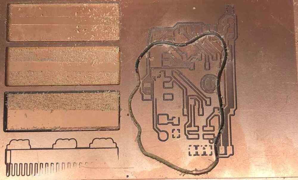
All four results (3018 after deburring):

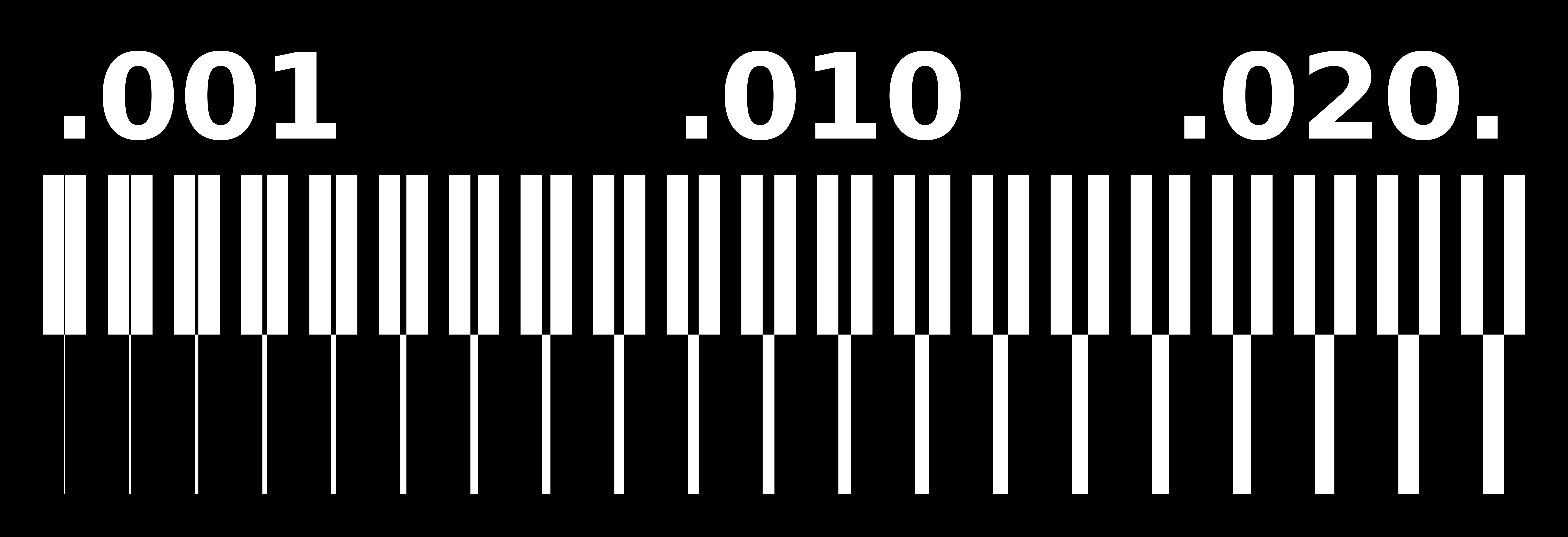
We also wanted to try out the V-bit, but we didn’t know which V-bit we had because it was gifted a couple of years ago. We determined the approximate angle of the V-bit in Illustrator like this:
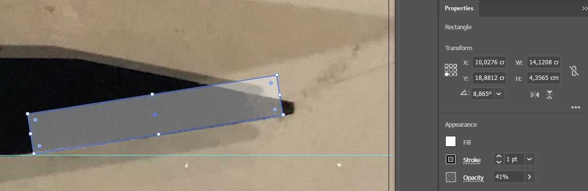
Since the V-bits start at a 10 degrees angle, we figured it would be that. The diameter of the tip we measured with a caliper. We didn’t use it in the end.