Prior knowledge
|
I have a basic experience in CNC, I followed the FabLab formation about a year ago. With my department, we even had the chance to recover an old CNC made from scratch that I had to repair and make work again. |
Hero shot
CNC
I first followed a formation by Christophe REYNTIENS, a Fab Academy 2019 student, to fabricate a G-code file for the CNC machine and how to operate said machine.
-
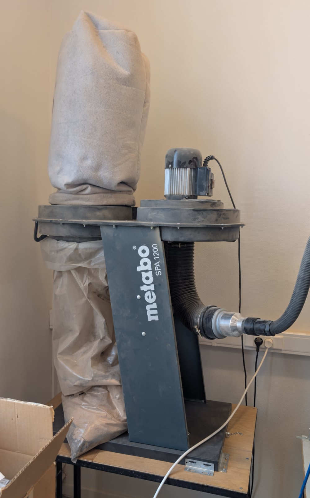
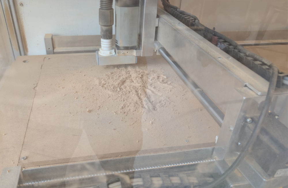
CNC machine
The model of the CNC is a High-Z S-1000/T by CNC-STEP (software : LinuxCNC). The FabLab ULB also built a case around with safety measures.
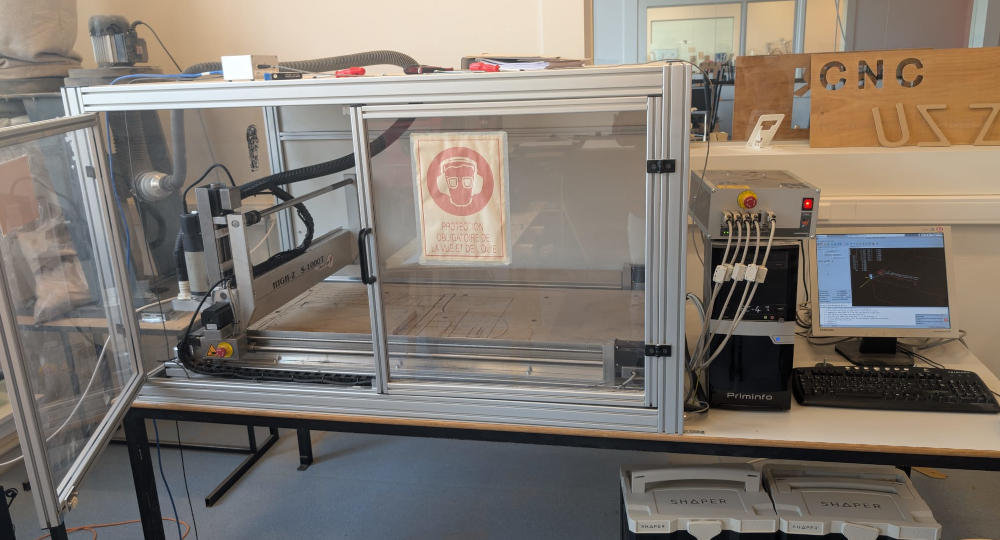
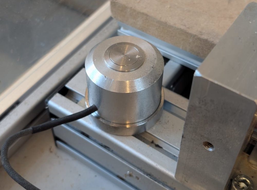
X Axis Travel Y Axis Travel Z Axis Travel Steps per Revolution 1/10 Micro-Step 1000 mm 600 mm 110 mm 2000 It also has a button to find the machine's origin.
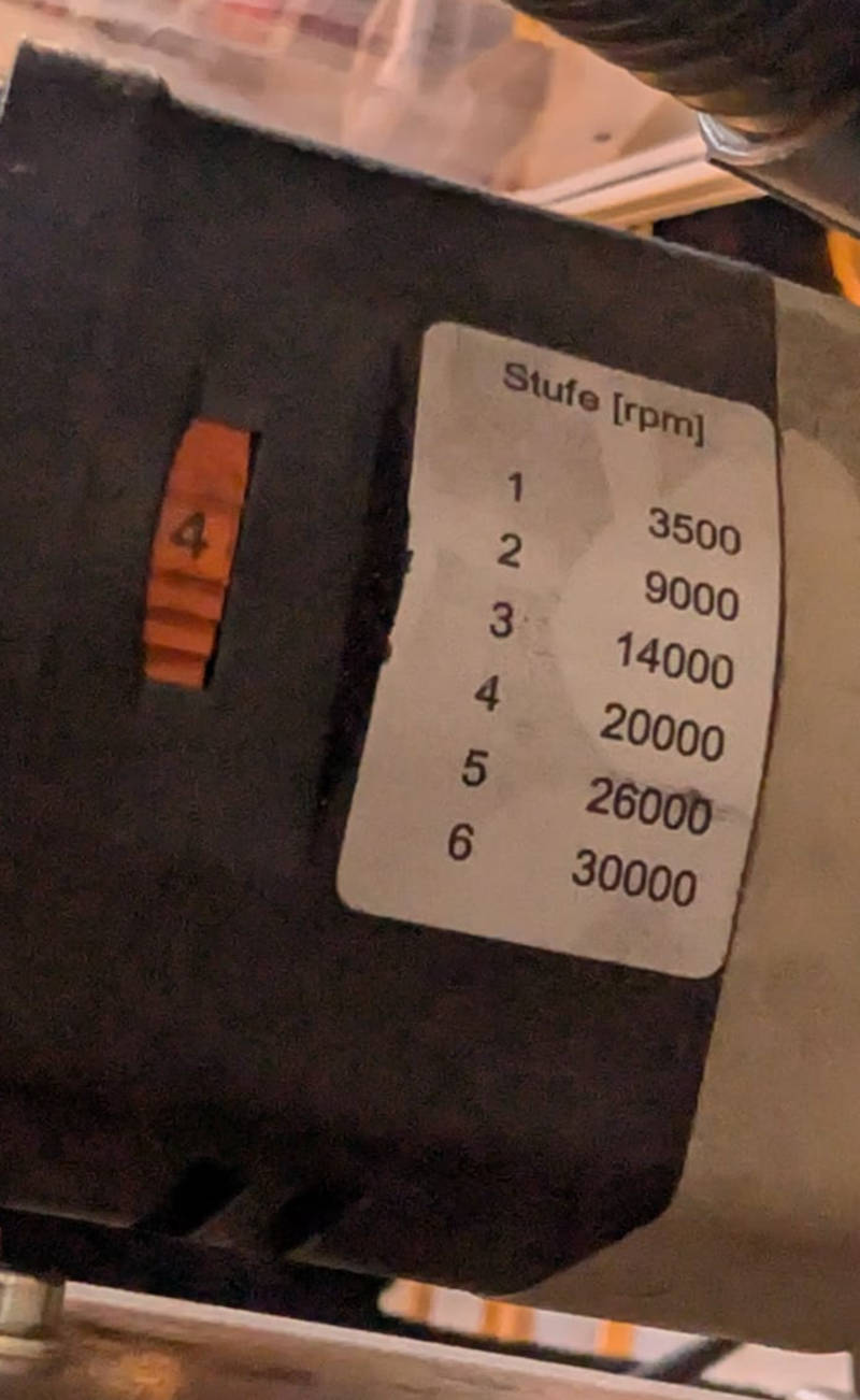
The spindle (the motor that holds the end mill) has a ON/OFF switch and a rotary switch to choose the speed at which it will turn.
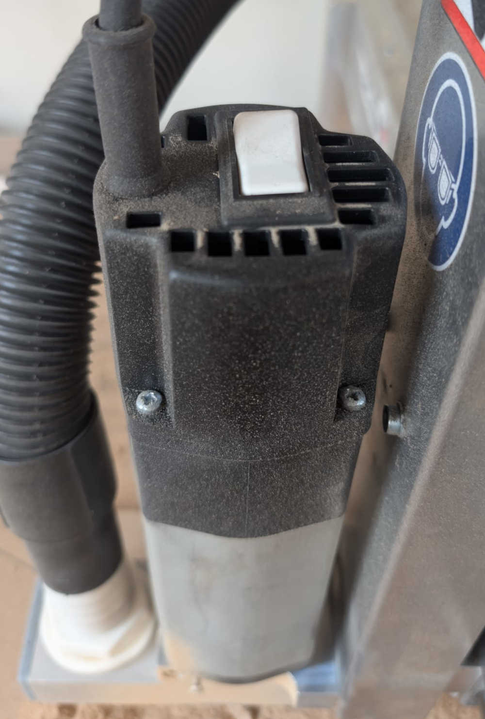
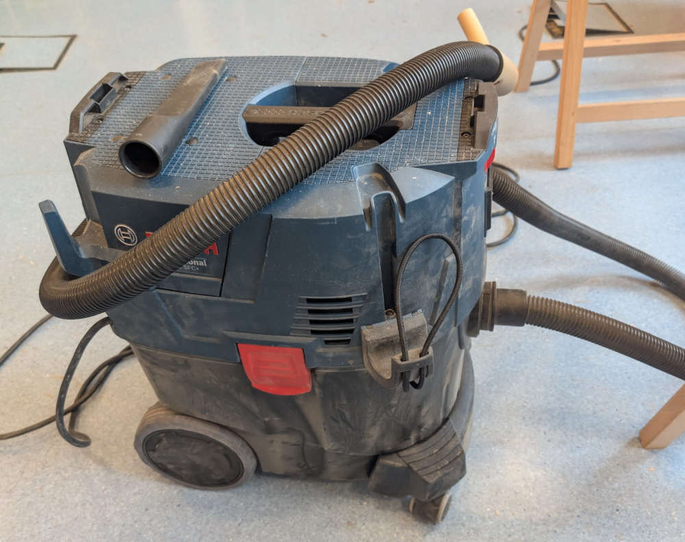
To clean the leftovers during or after a workpiece, the CNC has a stationary vacuum cleaner but after a few years, it doesn't work that well, so I have to use a portable one.
The machine has an integrated security in case someone opens the doors while there is a work, it should pause the machine and the spindle.
In case of a fire, there is a fire extinguisher and a fire blanket in the room where the CNC is.
-
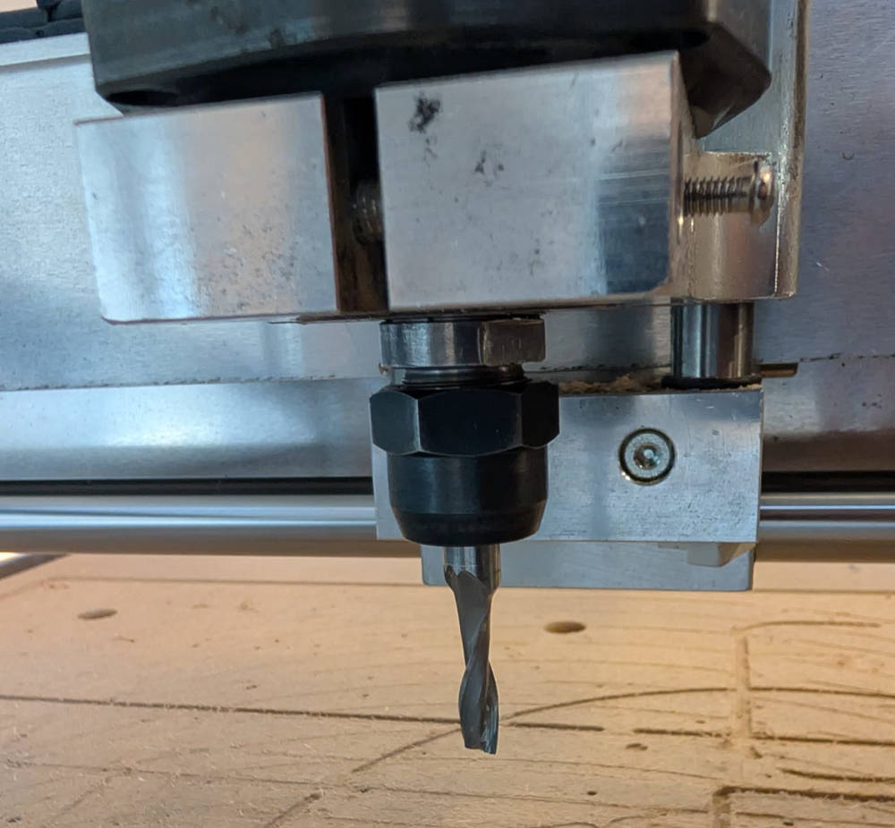
Assembling an end mill and a collet
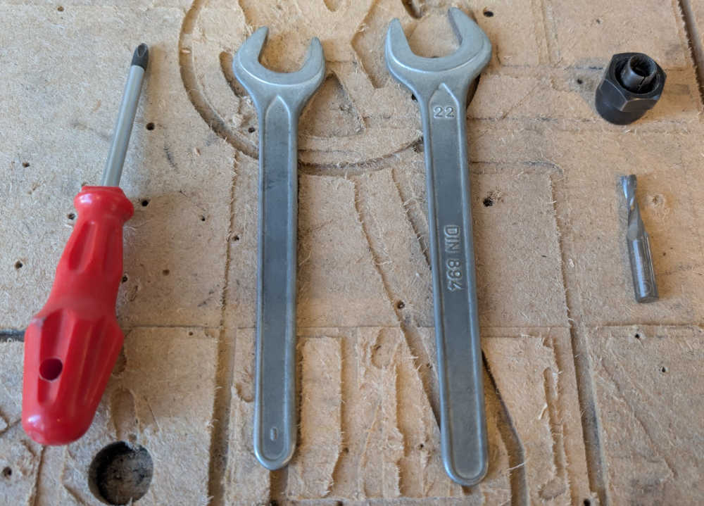
Here is a step by step guide to assemble an end mill and a collet to the CNC :
Two wrenches and a screwdriver are enough to assemble the pieces together.
I have to insert the end mill in the collet, not too high and not too low.
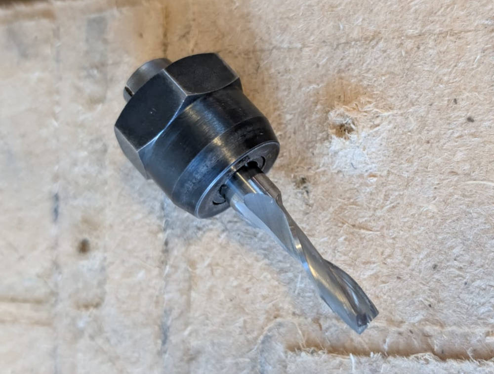
Then, I insert the end mill and collet combo in the spindle.
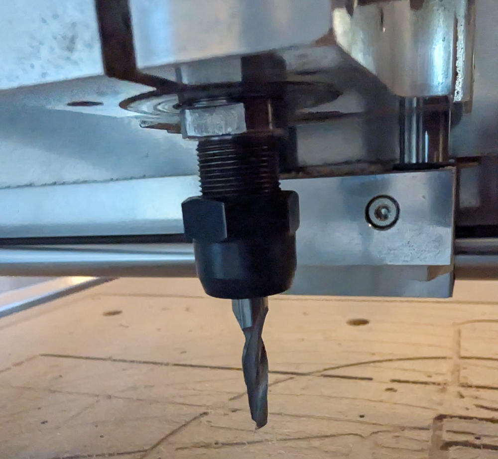
I assemble them first with my hands then finish with the wrenches.
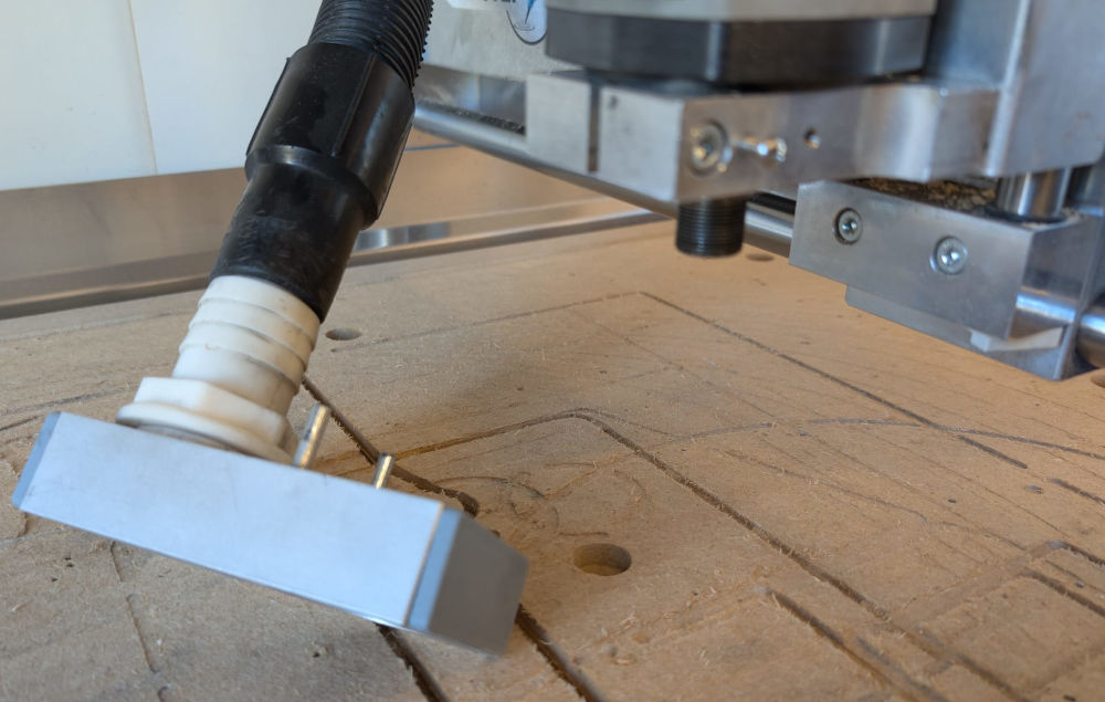
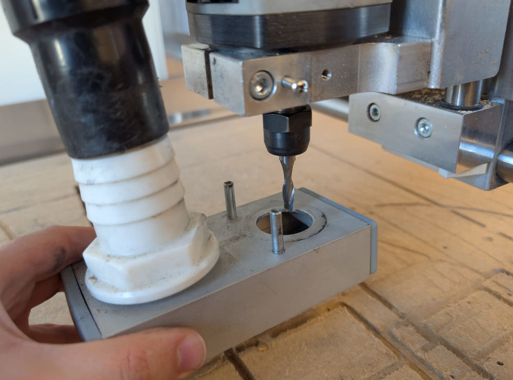
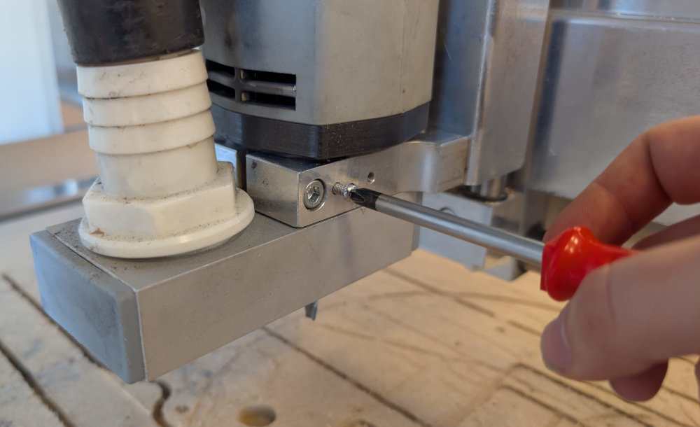
When they are assembled, I have to put back the vacuum cleaner part and screw it to the spindle holder.
-
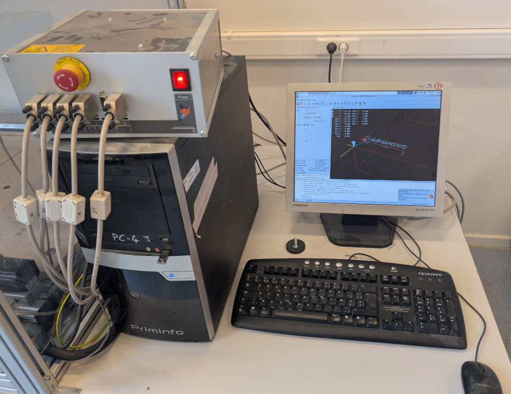
LinuxCNC
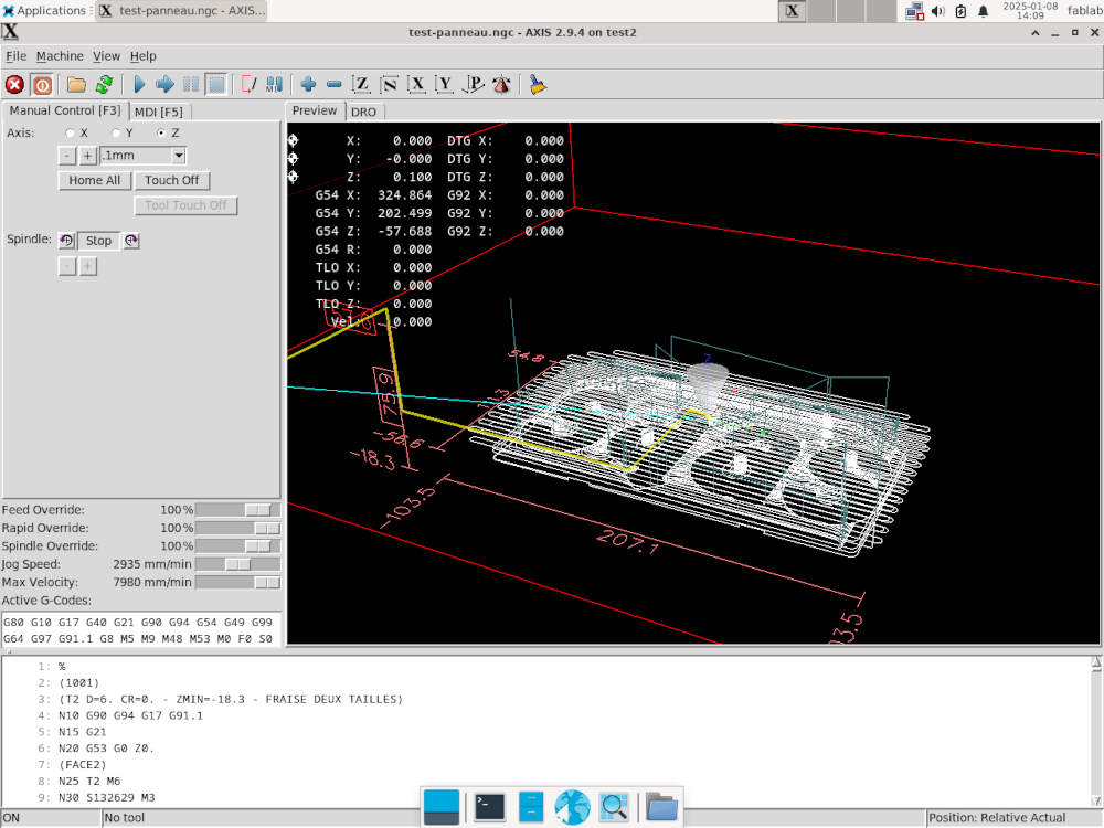
To start a workpiece, everything starts with the software, LinuxCNC, which was already installed on the computer. When opening it, I have to choose the latest and best configuration made by the FabLab ULB.
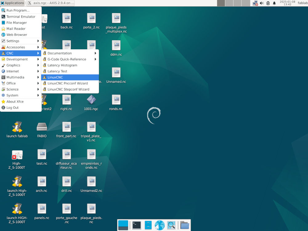
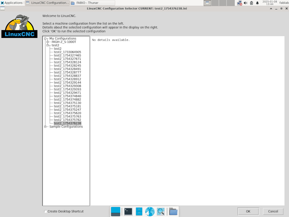
Here's its interface :
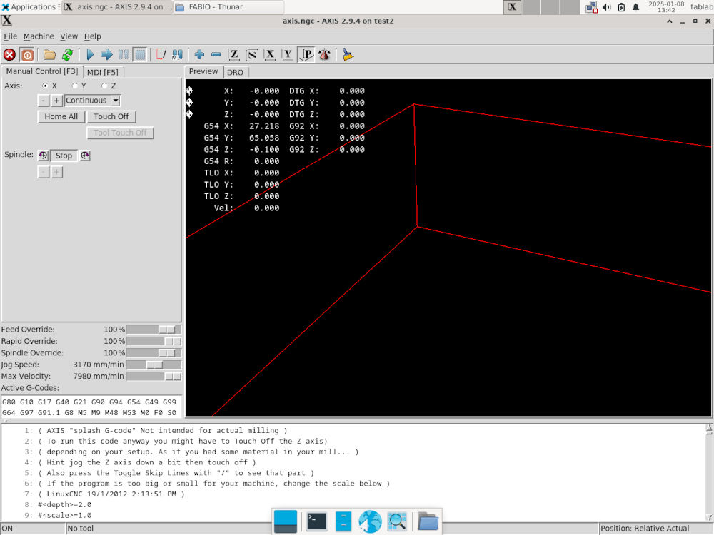
To launch a workpiece :
- Turn CNC machine on;
- On LinuxCNC, press the red square "Toggle Machine Power";
- Open G-code file of the workpiece;
- Press "Home All" for the machine to find its machine origin;
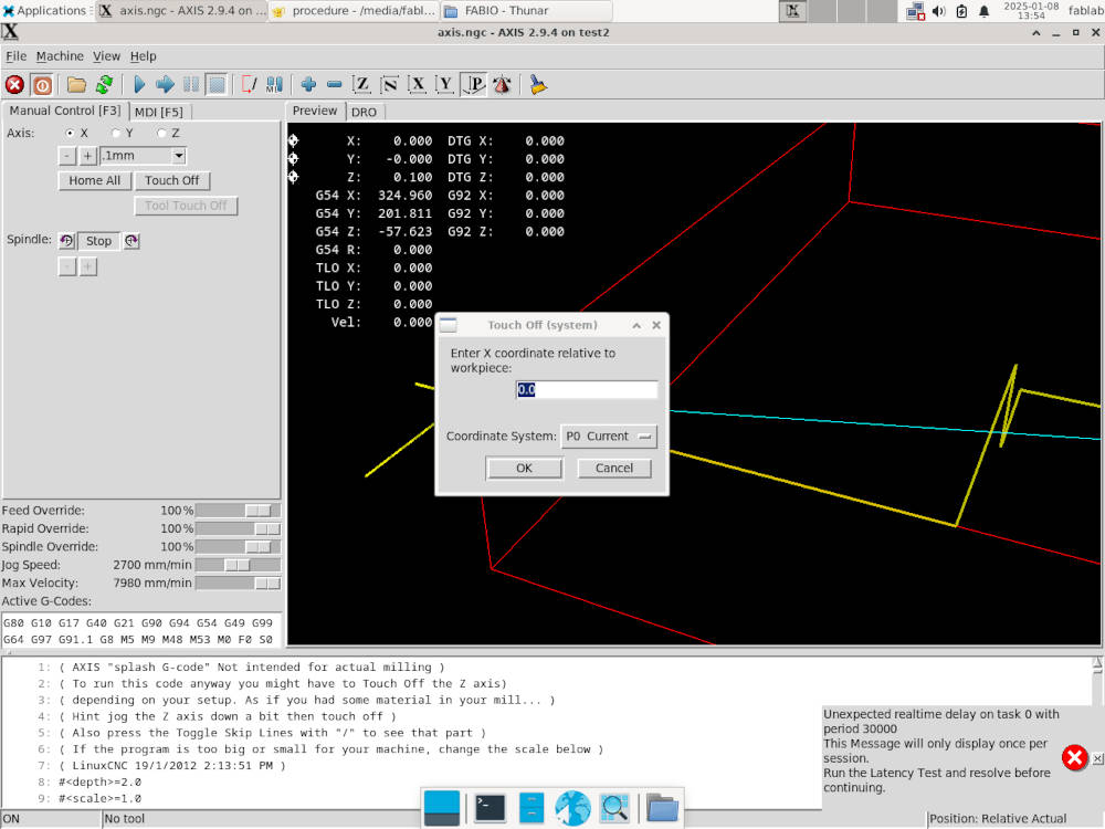
- By selecting "X" and "Y", configure the position of the end mill by pressing "+" and "-" to be on top and the center of your workpiece, press "Touch Off" and type "0" for both "X" and "Y" to set the workpiece origin;
- To set the "Z" origin, configure the position of the end mill by pressing "+" and "-" to be on top and the center of your workpiece and add a piece of thin paper between the end mill and the workpiece and adjust until the paper "scratches", press "Touch Off" and type the thickness of the paper to set the "Z" of the workpiece origin;
- Press the play button "Begin executing current file".
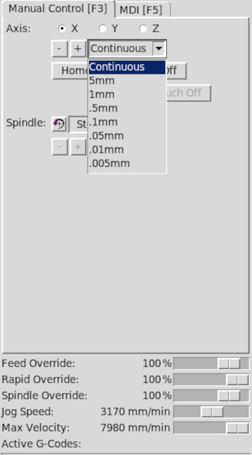
By pressing "Continuous", a drop-down list appears and I can change the range of the distance when pressing "+" and "-" for more precise movements.
By modifying "Jog Speed", I can change the speed of the motors to position the X, Y and Z axis faster, this doesn't affect the workpiece.
-
-
Formation test
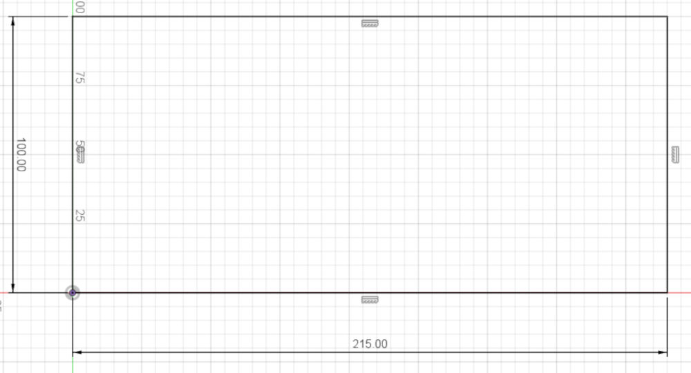
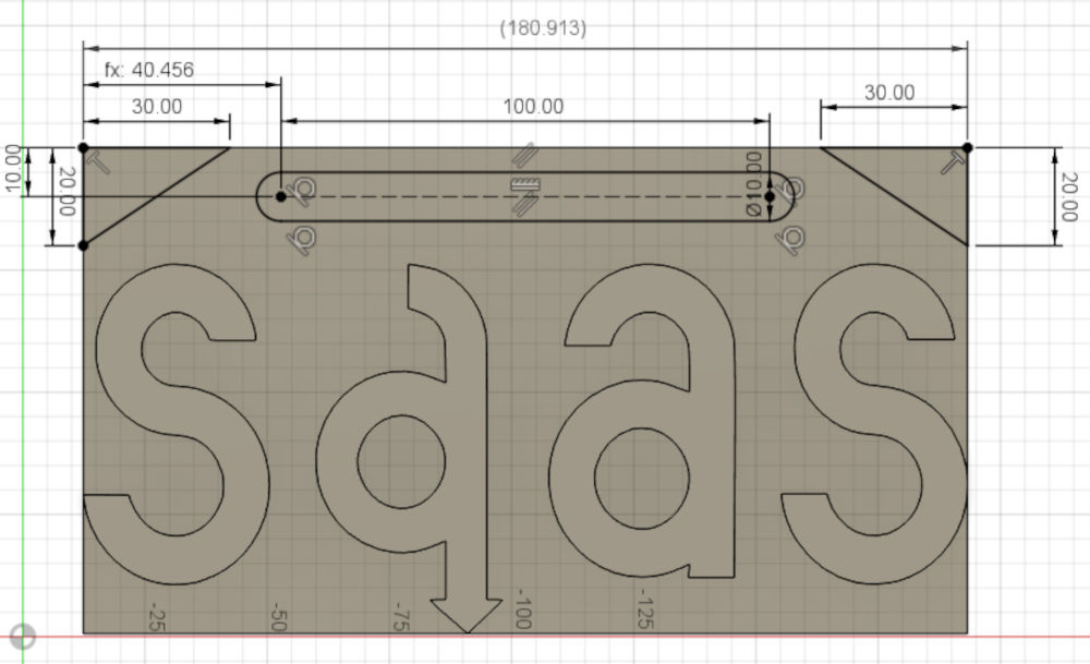
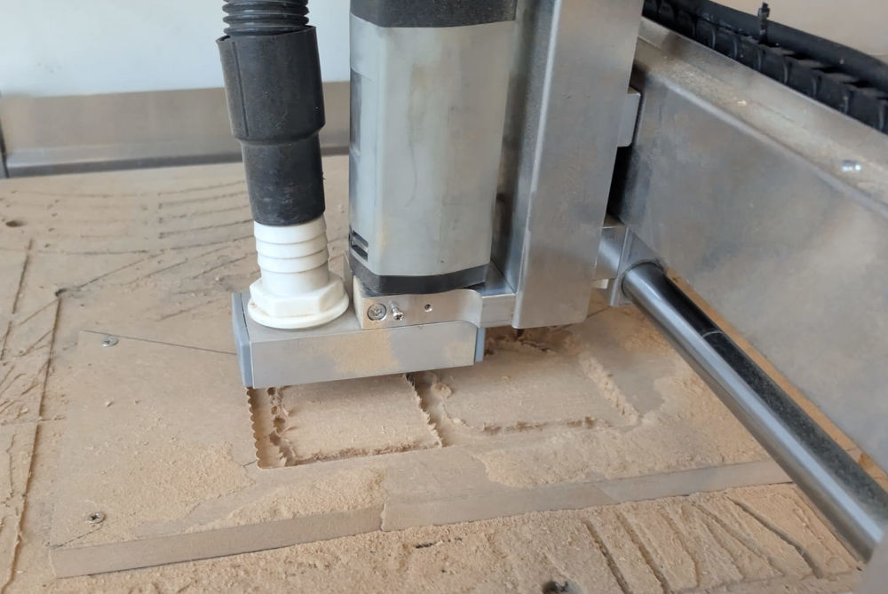
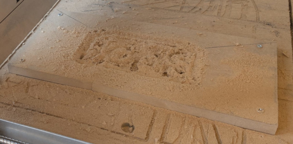
I was asked to make a tiny piece (~ 15 minutes of fabrication) to make sure we understood how the CNC works so I'll make a sign of my department.
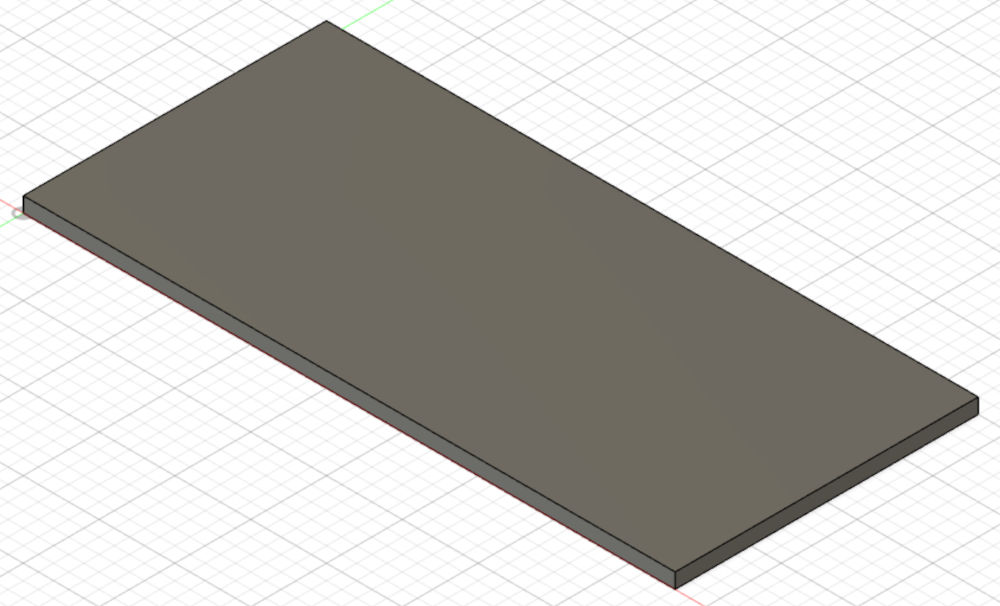
I start with a base big enough :
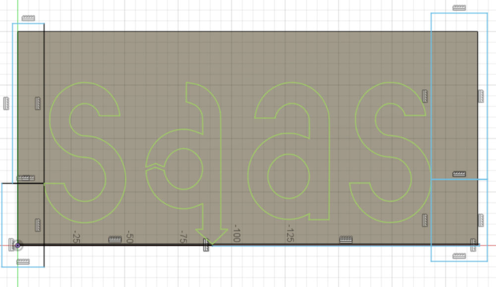
Then, I add an svg file of the logo of my department and reduce the size of the base :
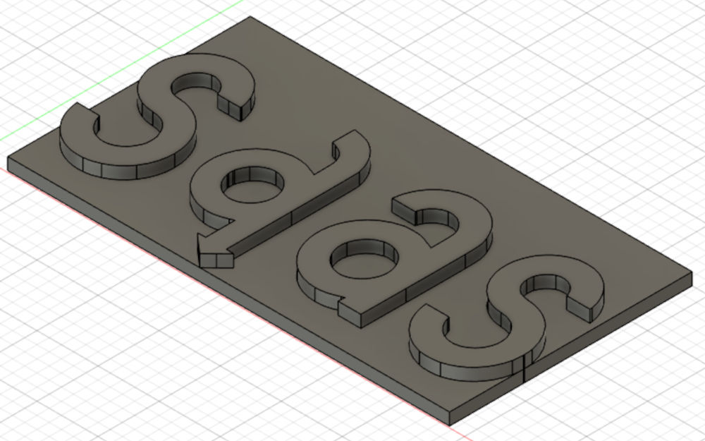
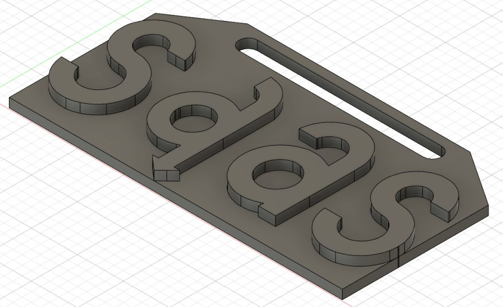
And finally, I had the hole and sharpen the top edges to give it the look of a sign :
-
Autodesk Fusion
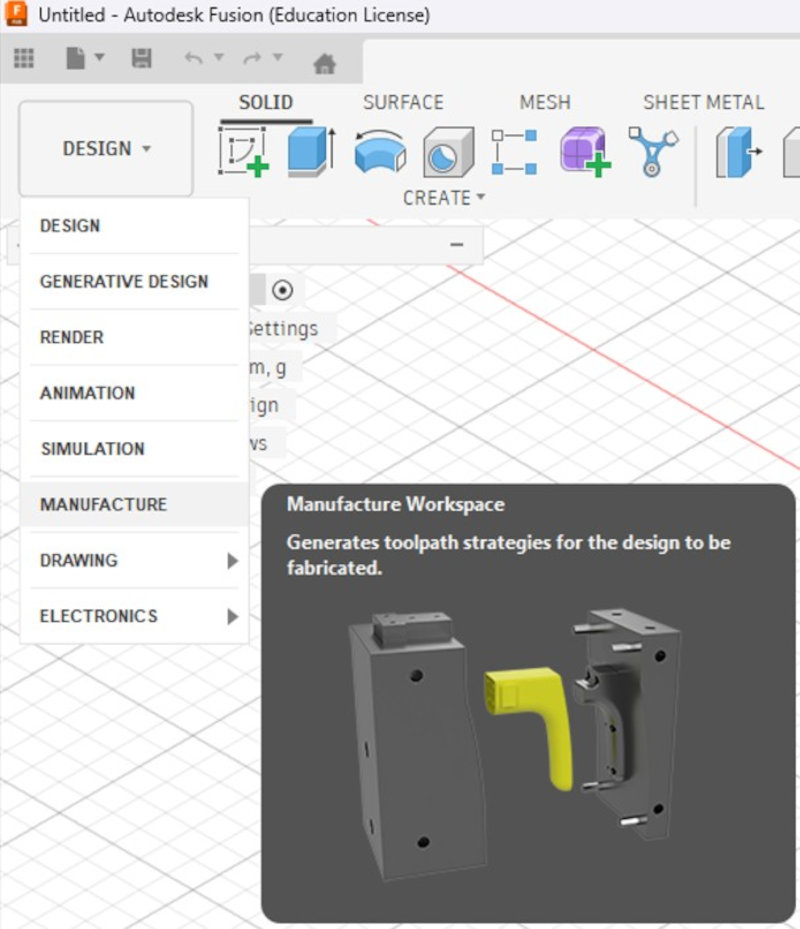
Before using the CNC, I have to use Autodesk Fusion to fabricate the G-code for my workpiece.
Once the 3D model is done, on the top left, I have to press "Design" and select "Manufacture" to enter its interface.
-
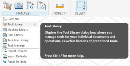
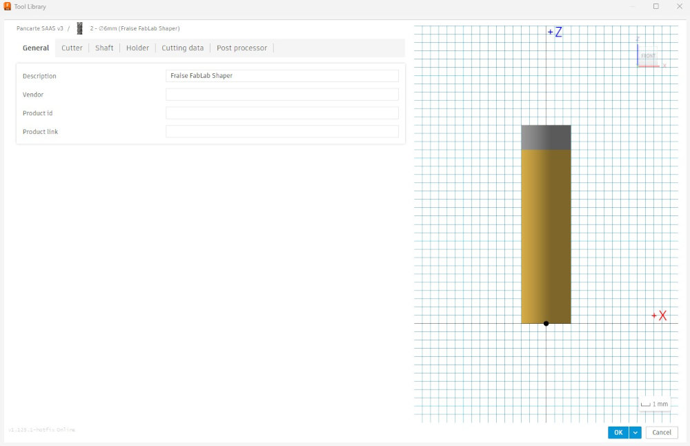
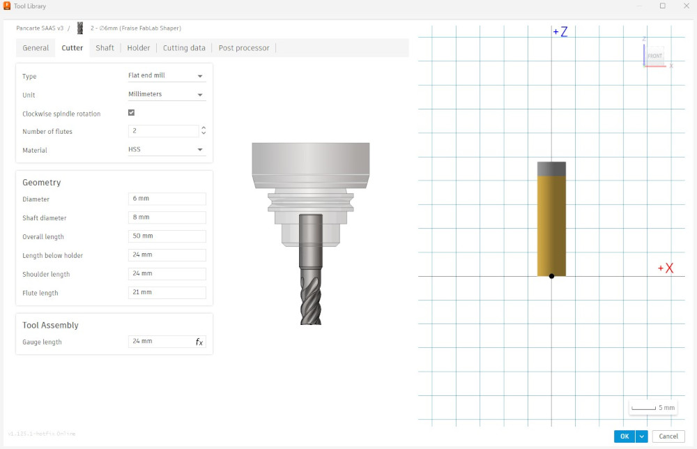
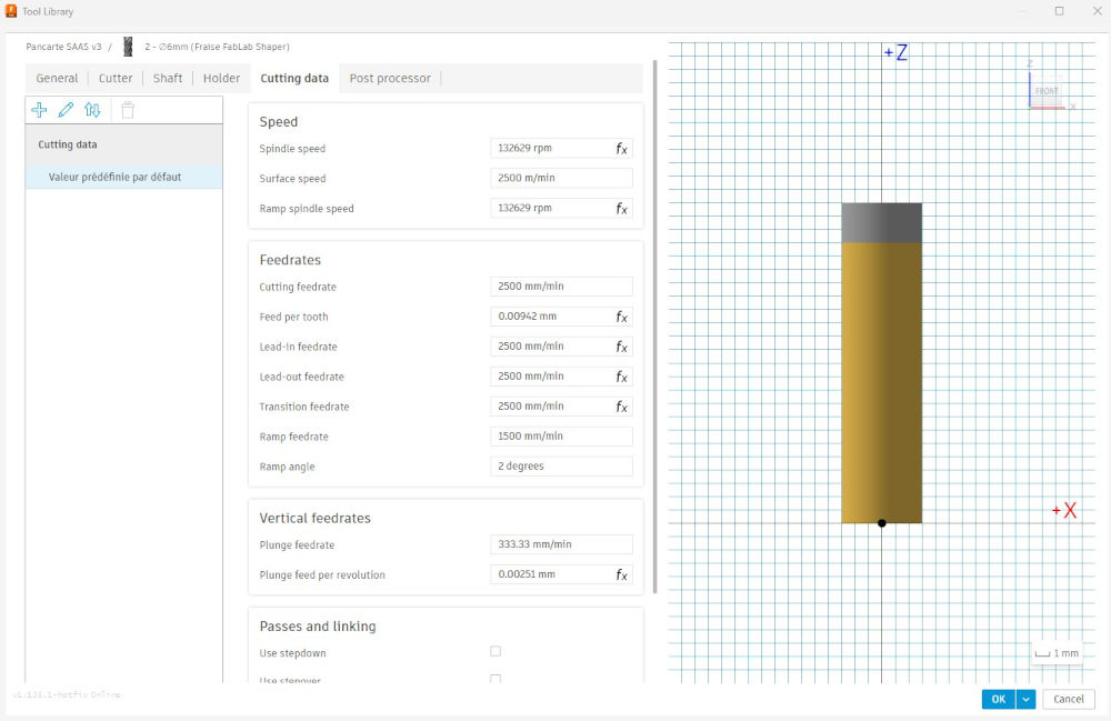
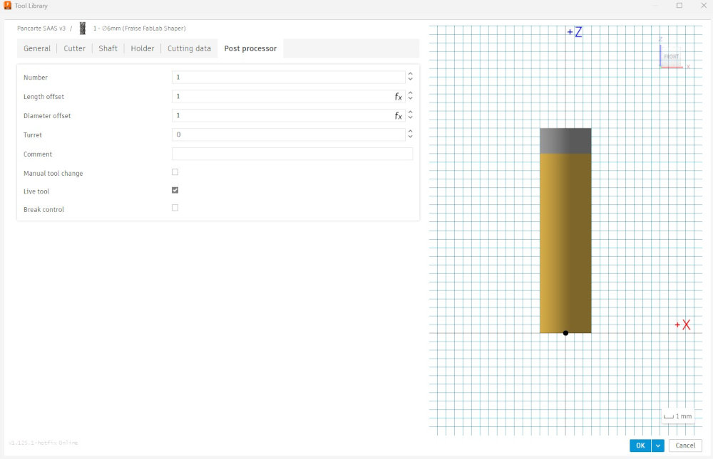
Tool
Before starting, I have to create the end mill I will use for this workpiece. For that, in the navigation bar, I have to press "Manage" and select "Tool Library".
The main characteristics I need about the end mill I will use are found here : Link 1 and Link 2.
Here are the parameters I edited :
-
Stock / Setup
I now need to add the stock and the origin of my workpiece, the stock is the piece of wood that serves as a base.
In the navigation bar, I have to press "Setup" and select "New Setup".
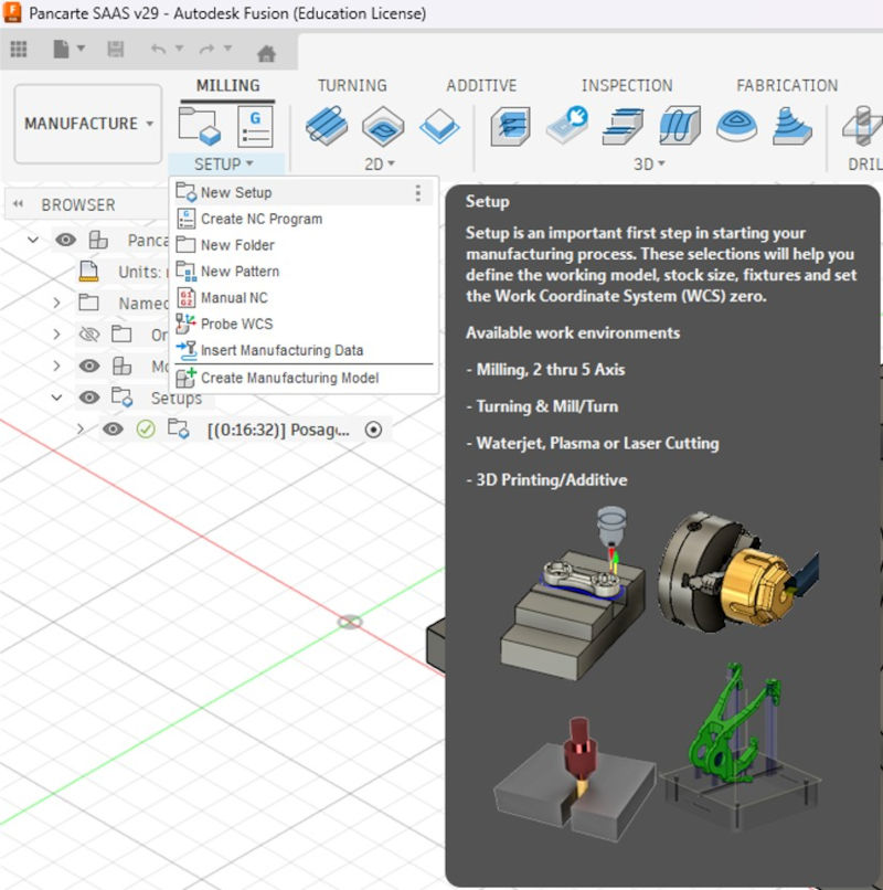
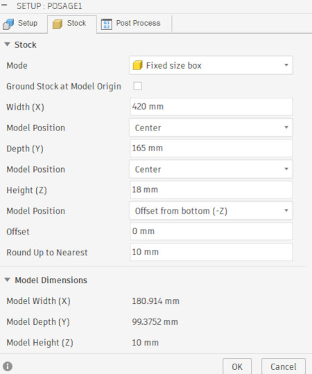
I have to type the correct dimensions of my stock and make sure the "Model Position" of the Z axis is at "Offset from bottom (-Z)" and type "0" so my workpiece is at the bottom of my stock and not centered.
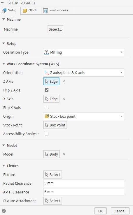
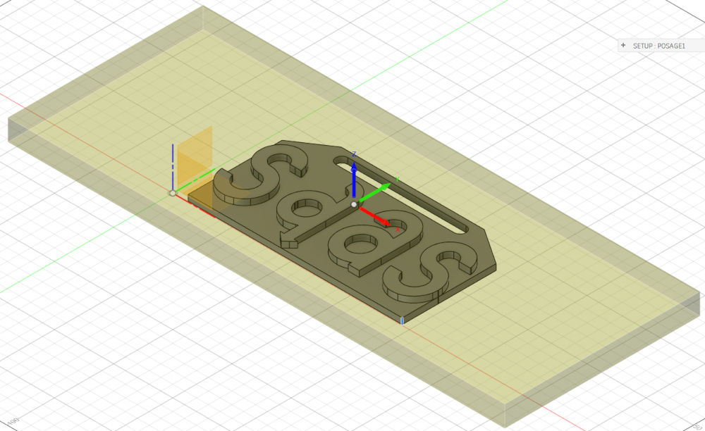
I have to select the Z and X axes and make sure the origin is on the top and in the center of my stock.
Now I can start manufacturing my stock. Autodesk Fusion proposes many functions. There are multiple ways to achieve our end goal, the most important is to be efficient and fast.
Every time I choose a function, a window with multiple tabs appears on the right to edit the parameters and select what has to be manufactured, there are two tabs that will remain the same for the manufacture, the "Tool" and "Passes" tabs.
For the "Tool" tab, I have to choose the end mill I created and for the "Passes" tab, I only change the"Maximum Stepdown" value.
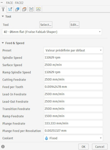
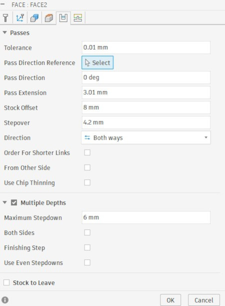
These tabs remain the same for the following functions.
-
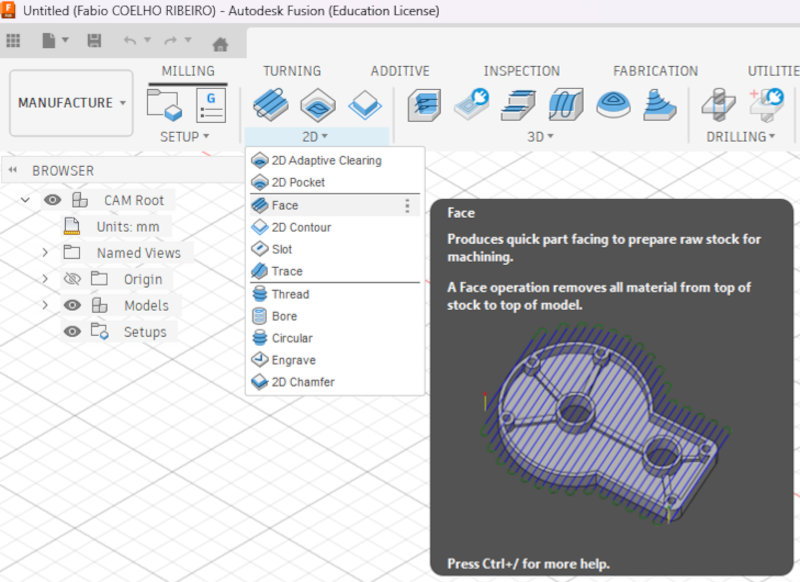
Face
Used to get rid of excess stock on the top.
In the navigation bar, I have to press "2D" and select "Face".
In the "Tool" and "Passes" tabs, I choose the previous parameters.
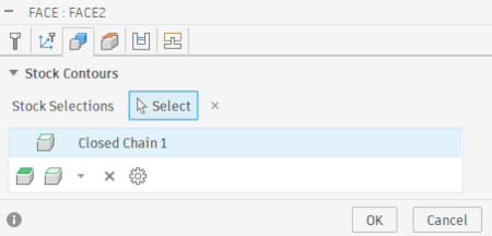
In the "Geometry" tab, I have to select the contour of the excess stock I want to remove on the top.
Final result of operation :
-
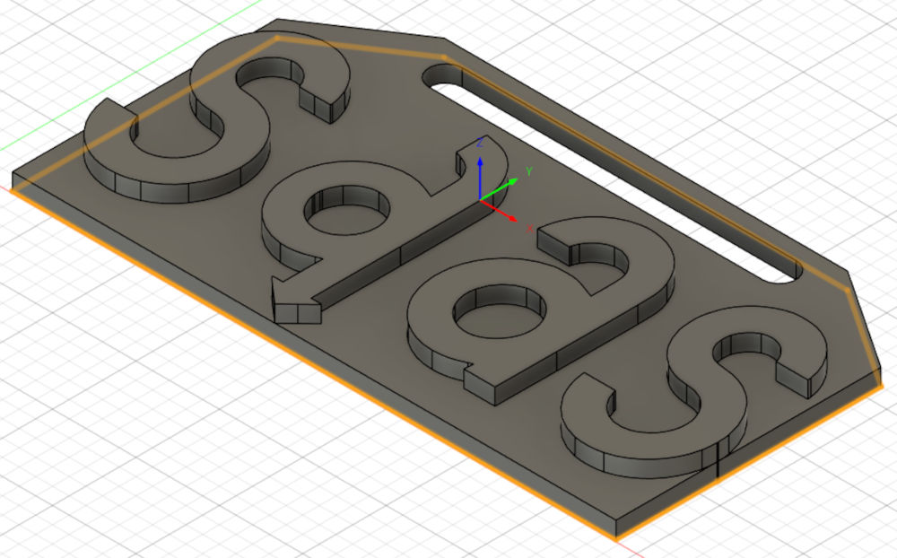
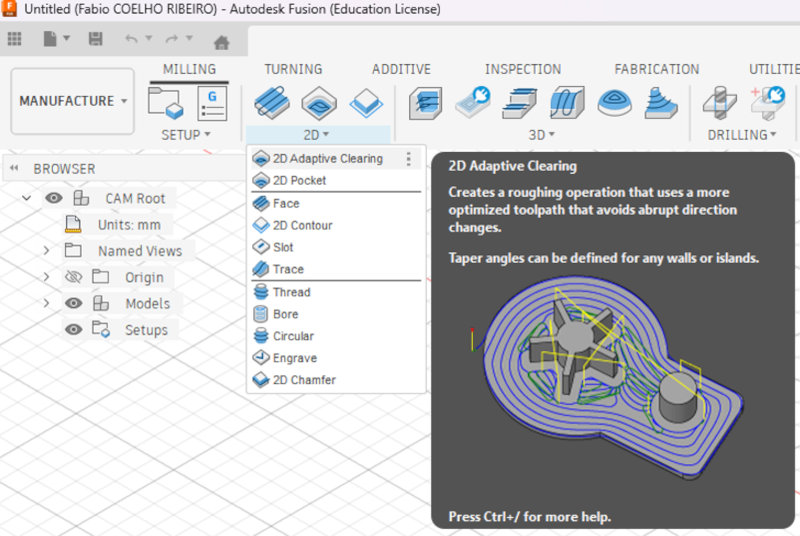
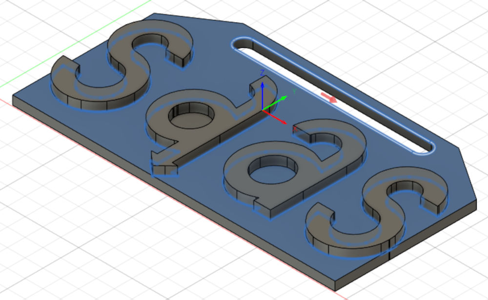
2D Adaptive Clearing
Used to get rid of excess stock of an open hole.
In the navigation bar, I have to press "2D" and select "2D Adaptive Clearing".
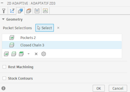
In the "Tool" and "Passes" tabs, I choose the previous parameters.
In the "Geometry" tab, I have to select the face of the the excess stock I want to remove, I mustn't forget the little slot on the top.
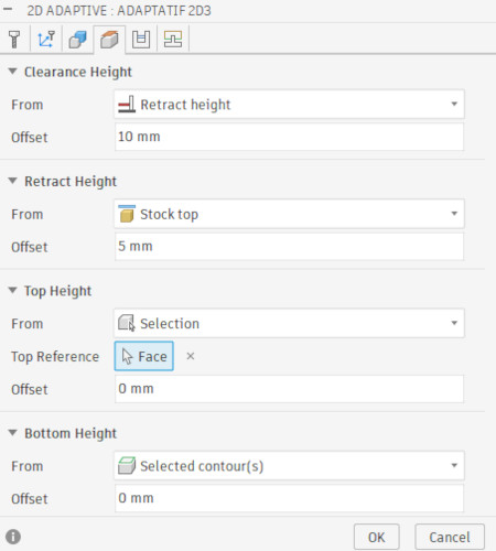
Since I already removed excess on the top, I can start the function a bit lower, for that in the "Heights" tab, I have to change the "Top Height", select "Selection" and choose the top of a letter.
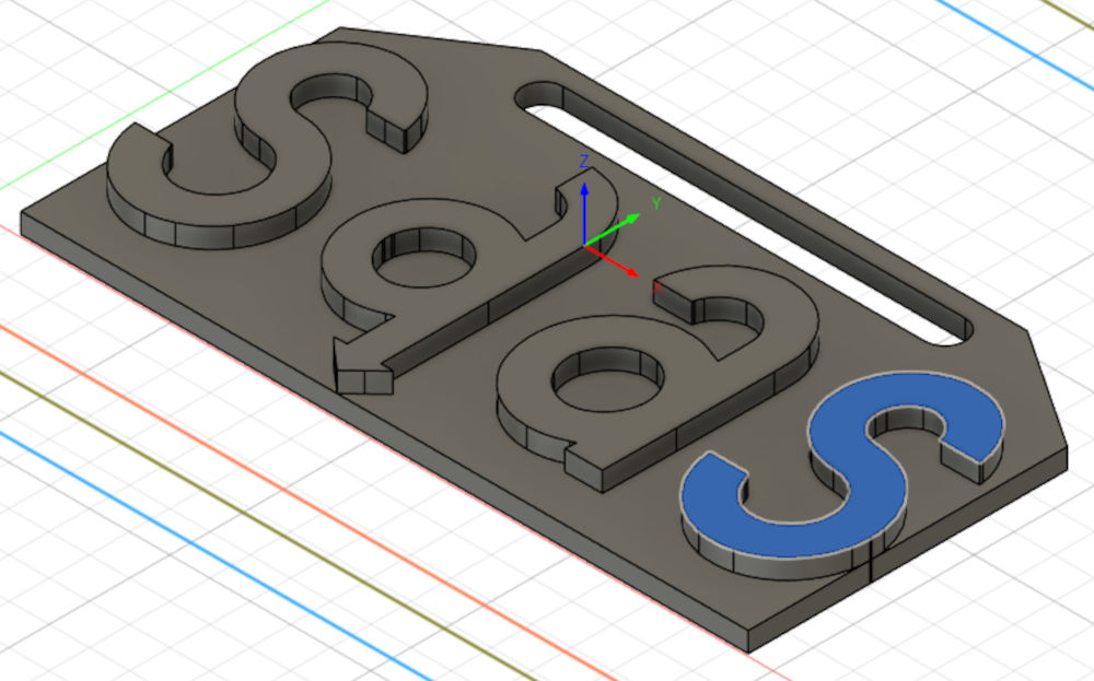
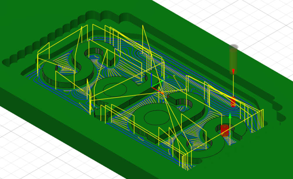
Final result of operation :
-
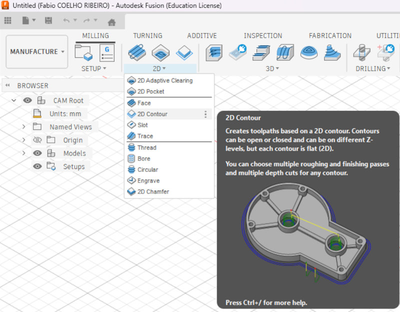
2D Contour
Used to get rid of excess stock that leads to a open or closed hole and have a better finish with a shorter end mill.
In the navigation bar, I have to press "2D" and select "2D Contour".
In the "Tool" and "Passes" tabs, I choose the previous parameters.
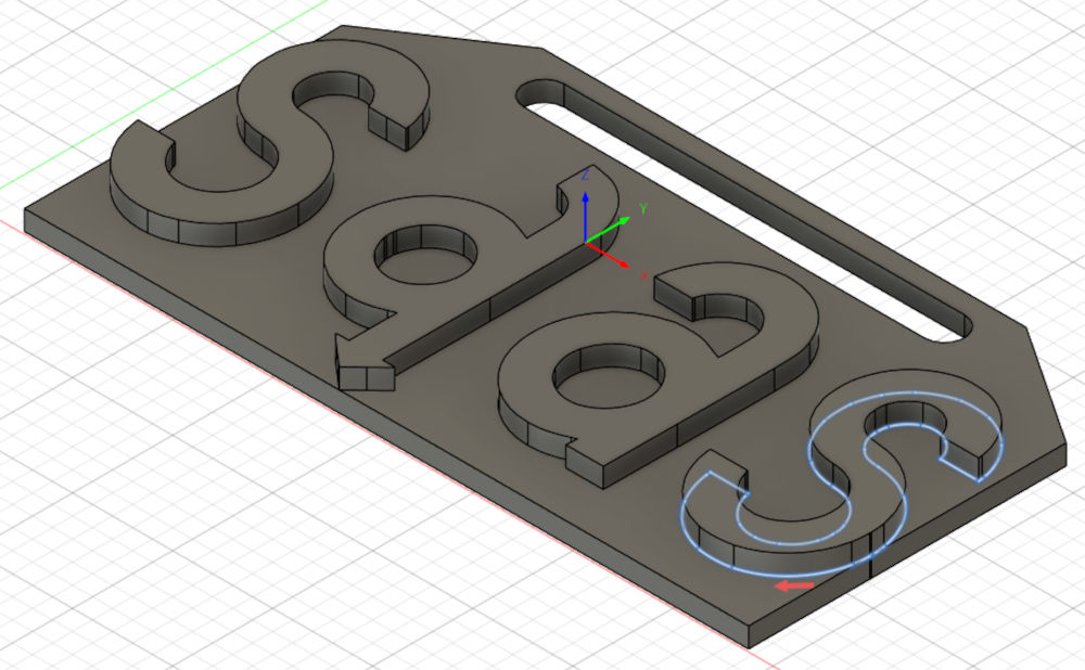
Unfortunately, the 2D adaptive clearing didn't fully remove the excess stock of the second "S", so I''ll do a 2D contour to remove it.
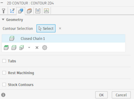
In the "Geometry" tab, I have to select the contour of the the excess stock I want to remove.
I can again lower the height where the function will start.
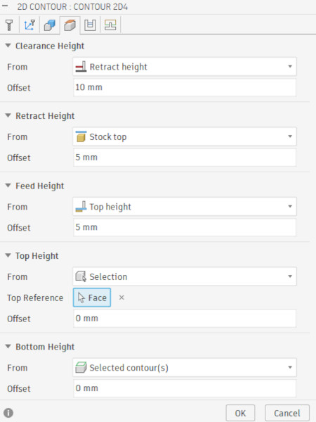
Final result of operation :
-
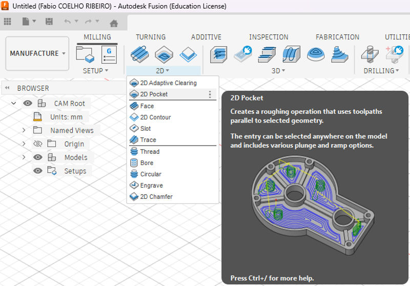
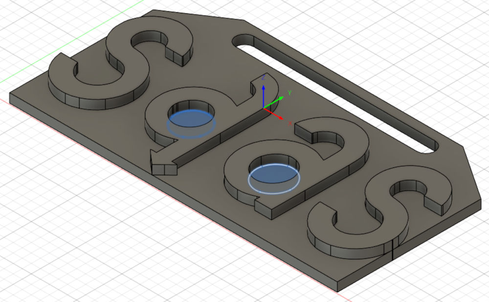
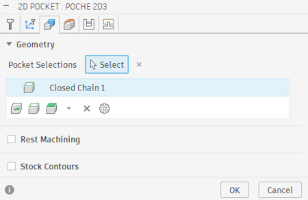
2D Pocket
Used to get rid of excess stock of a closed hole.
In the navigation bar, I have to press "2D" and select "2D Pocket".
In the "Tool" and "Passes" tabs, I choose the previous parameters.
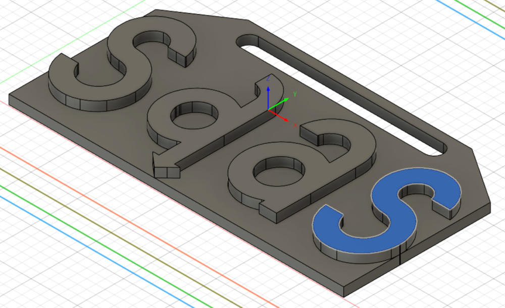
Now, I'll remove the excess stock of the closed holes.
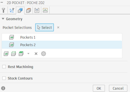
In the "Geometry" tab, I have to select the hole of the the excess stock I want to remove.
I can again lower the height where the function will start.
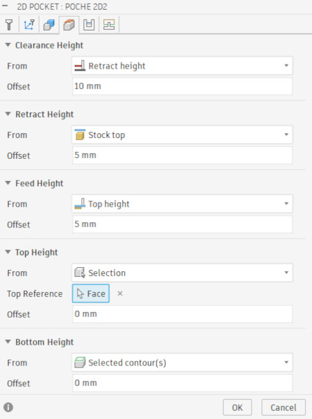
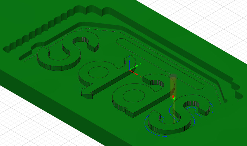
Final result of operation :
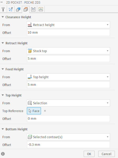
Let's not forget the little slot on the top.
In the "Geometry" tab, I have to select the hole of the the excess stock I want to remove.
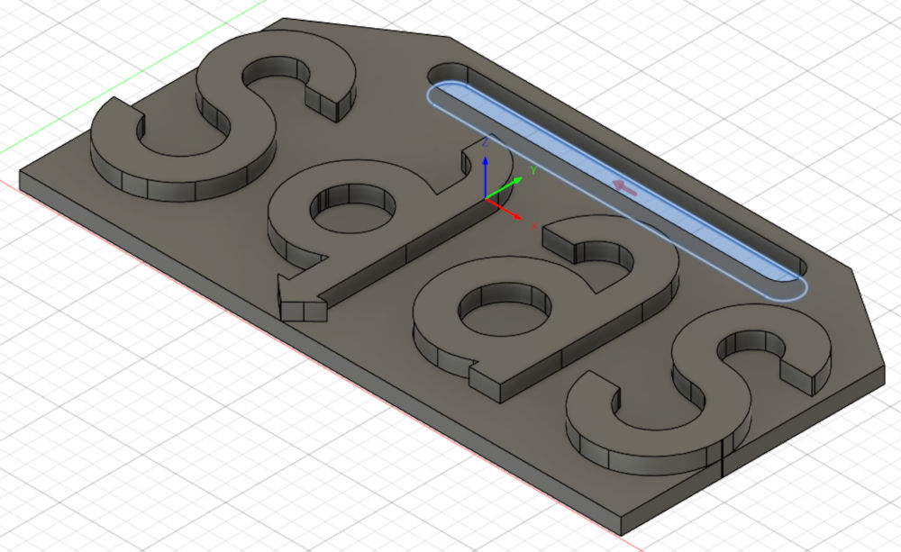
Here, I can go even lower for the height where the function will start. I can even change "Bottom Height" to go in the negative to make sure the end mill will go all the way through and make sure I have a hole.
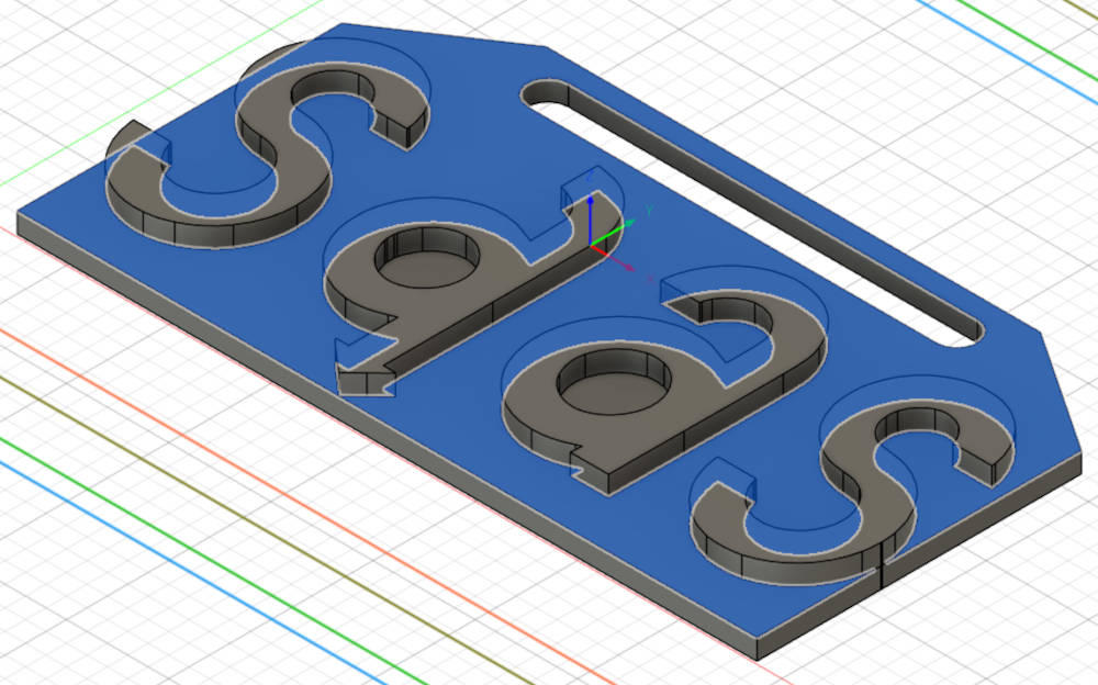
Final result of operation :
-
Final Contour
Used to separate the workpiece from the stock.
In the navigation bar, I have to press "2D" and select "2D Contour".
In the "Tool" and "Passes" tabs, I choose the previous parameters.
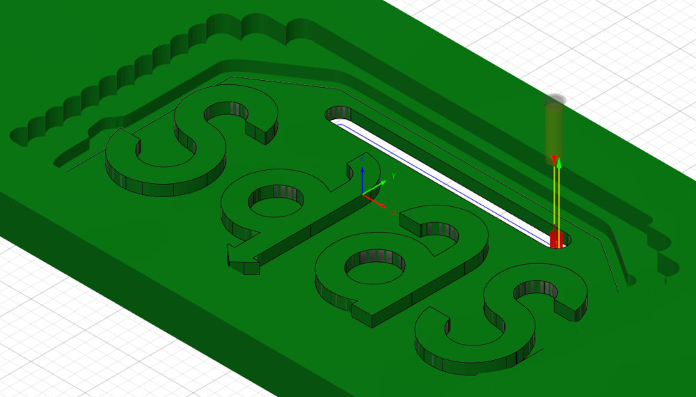
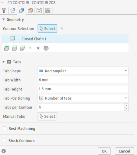
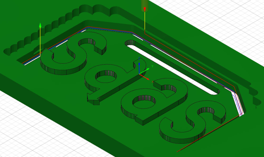
In the "Geometry" tab, I have to select the contour of the workpiece. I also add tabs, which are little pieces of wood that connect the workpiece to the stock to make sure it wont fly when the contour is done.
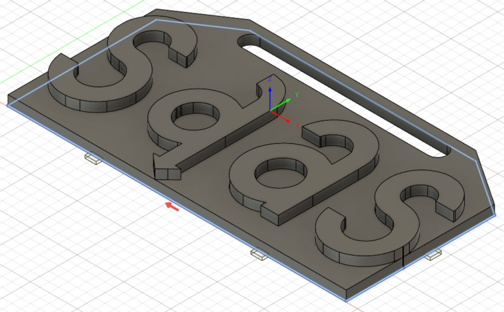
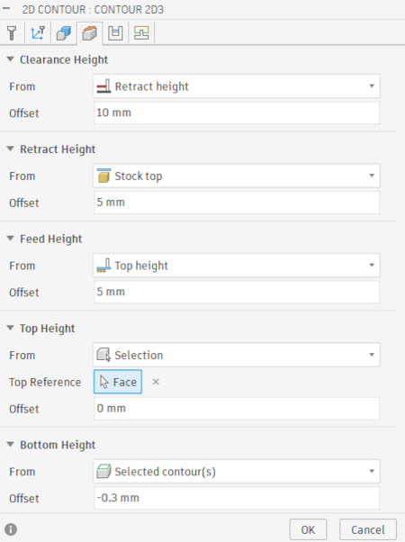
I can again lower the height where the function will start and again, I change the "Bottom Height" to go in the negative to make sure I have a hole.

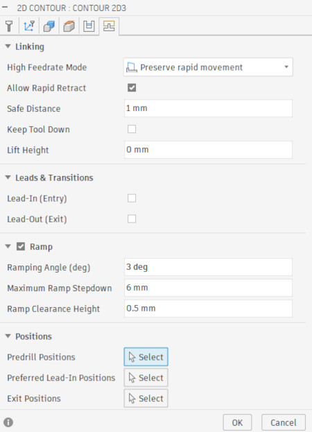
Here, based on Christophe's experience, I uncheck "Lead-In (Entry)" and "Lead-Out (Exit)" and add "Ramp" with the following parameters for better efficiency :
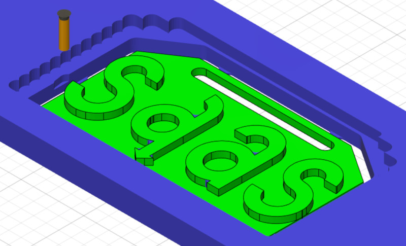
Final result of operation :
-
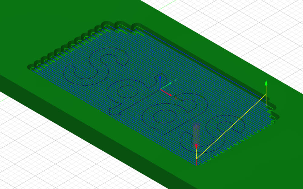
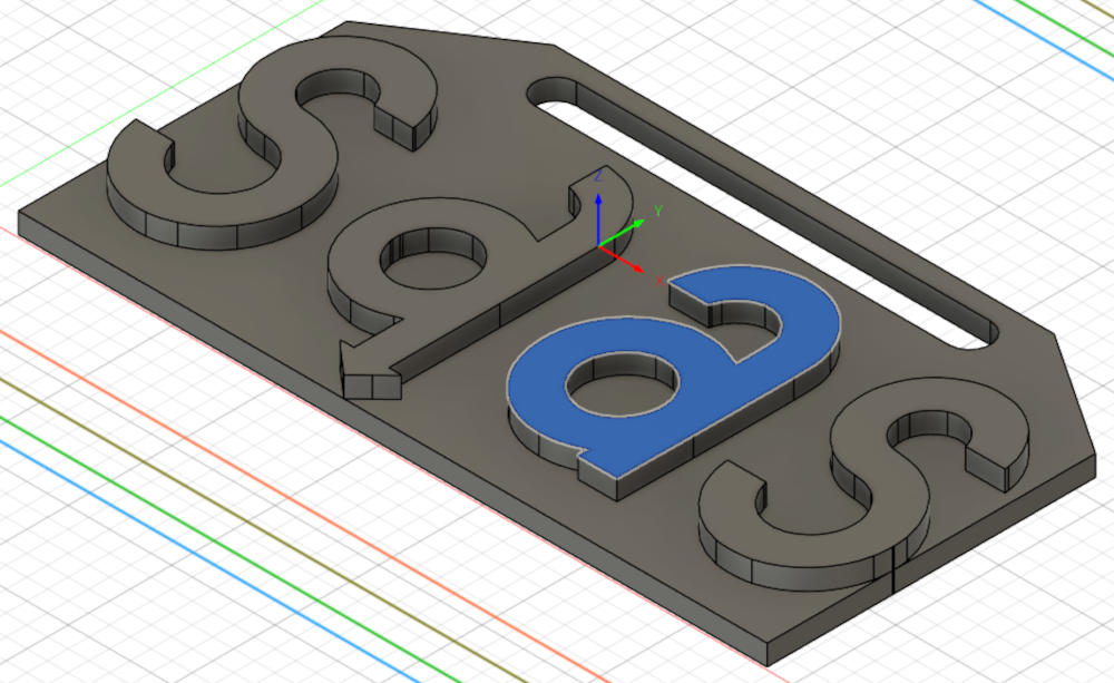
Simulation
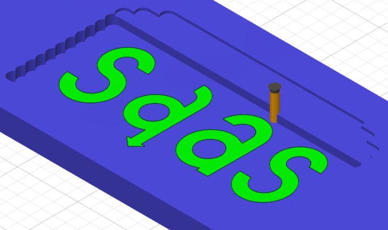
Autodesk Fusion also proposes a simulation of the entire manufacture (or a specific operation). This is useful to make sure there won't be any problems.
In the navigation bar, I have to press "Actions" and select "Simulate".
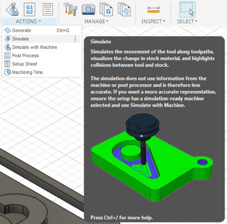
I can now press play, pause, next or previous step, ...
-
Post process
This is the final step to create the G-code file for the CNC.
In the navigation bar, I have to press "Actions" and select "Post Process".
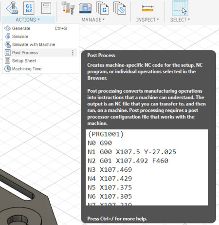
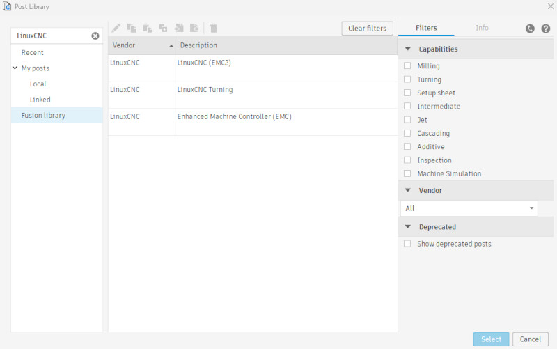
I have to select the good "Post" (based on the CNC and the software used), name my file and export.
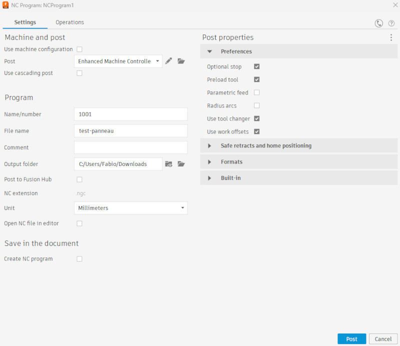
This is the post processor selection interface, I had to download mine from the post library from Autodesk Fusion due to problems (type LinuxCNC and download "Enhanced Machine Controller (EMC)") then import it in Autodesk Fusion.
-
-
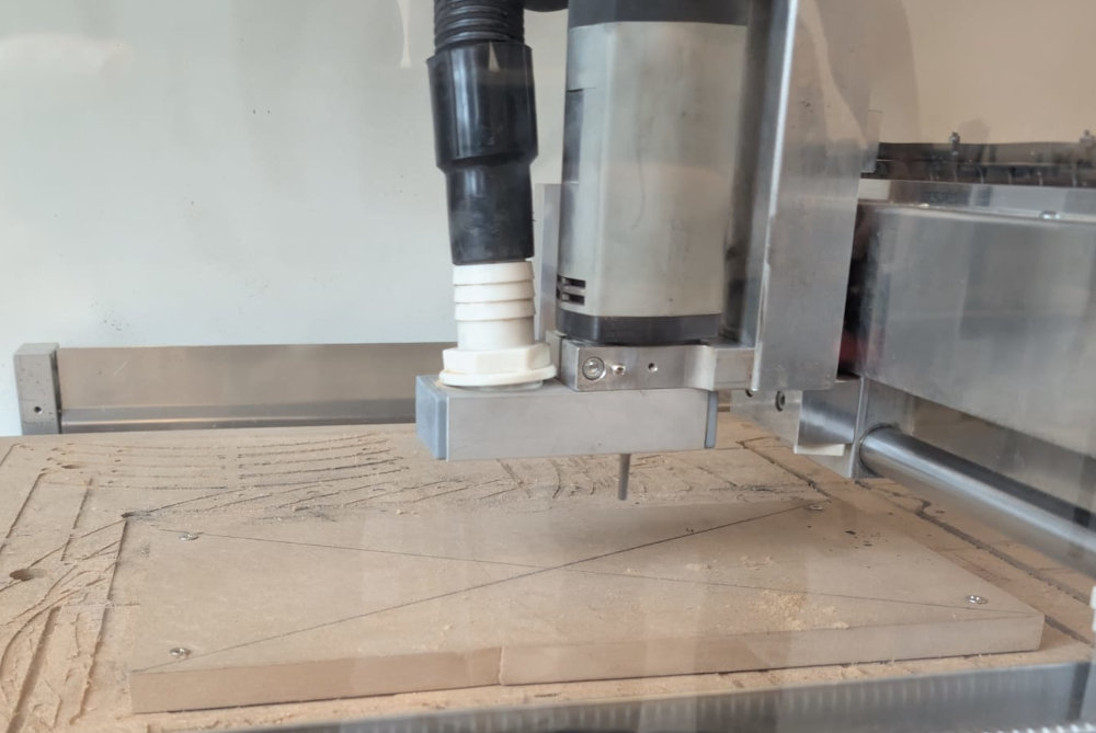
CNC Formation test
Now for the actual manufacture of the workpiece.
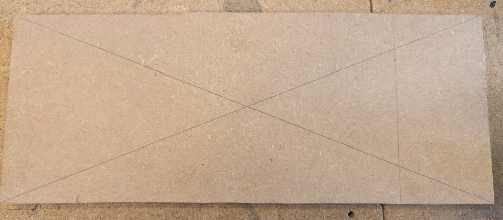
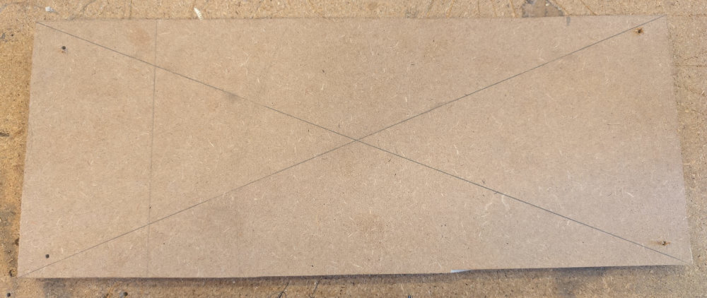
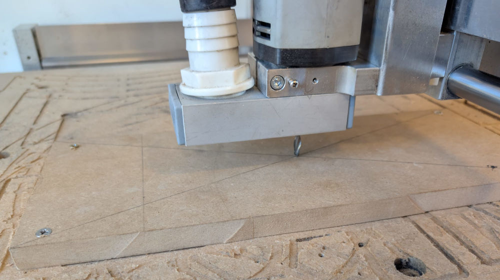
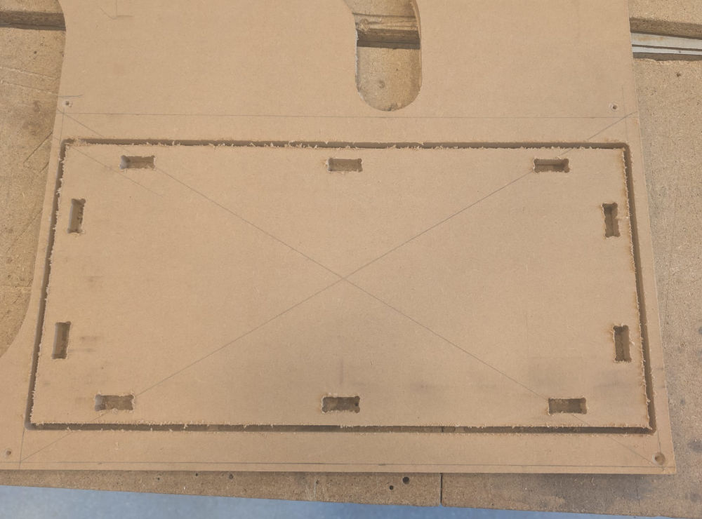
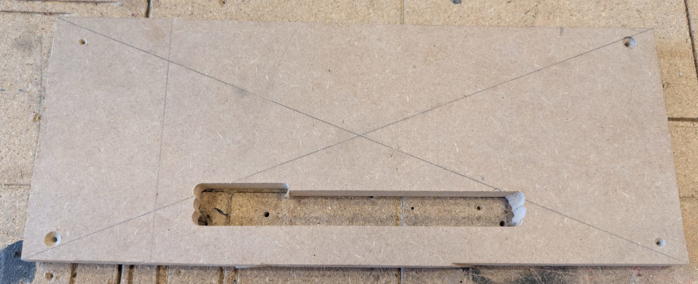
I start by choosing a piece of wood, draw the diagonals to have the center of the stock and drill 4 holes in the extremities.
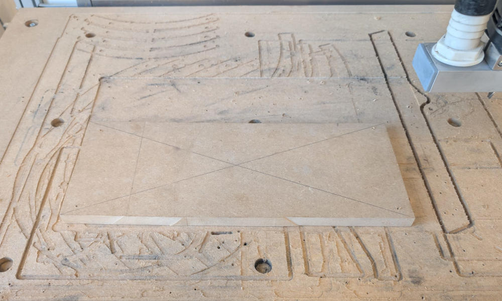
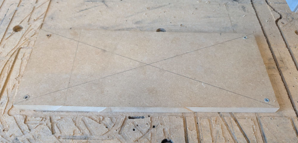
I then place the stock in the CNC working area and screw it to the spoilboard.
Then, I open my G-code file in LinuxCNC and configure X, Y and Z.
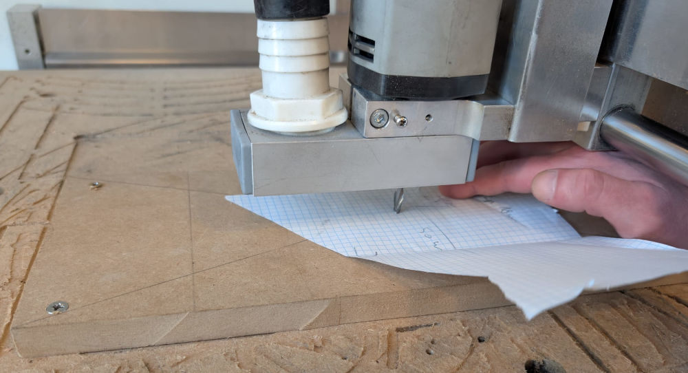
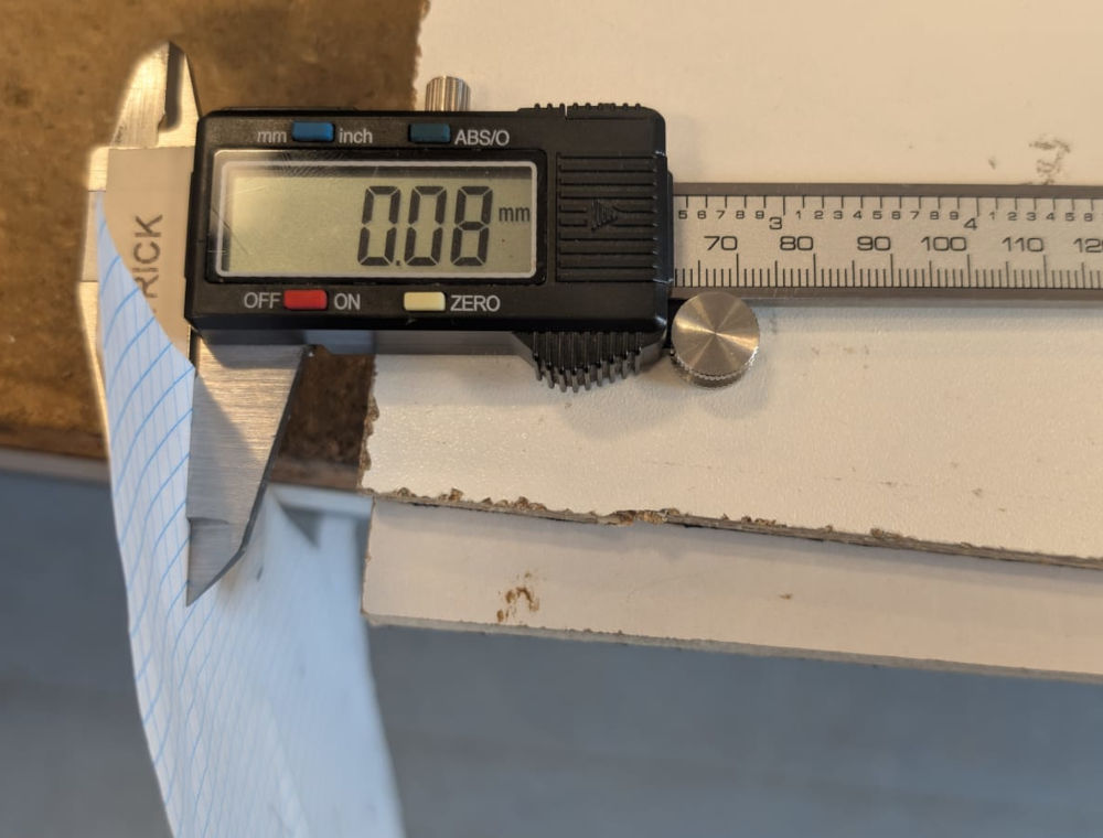
For the Z axis, since the button to find the machine's Z origin is broken, I have to do it the old way, with a piece of paper between the end mill and the stock and type "0,1" (approximate thickness of the paper) to set the Z origin.
Now, I simply click "Begin" to start the manufacture.
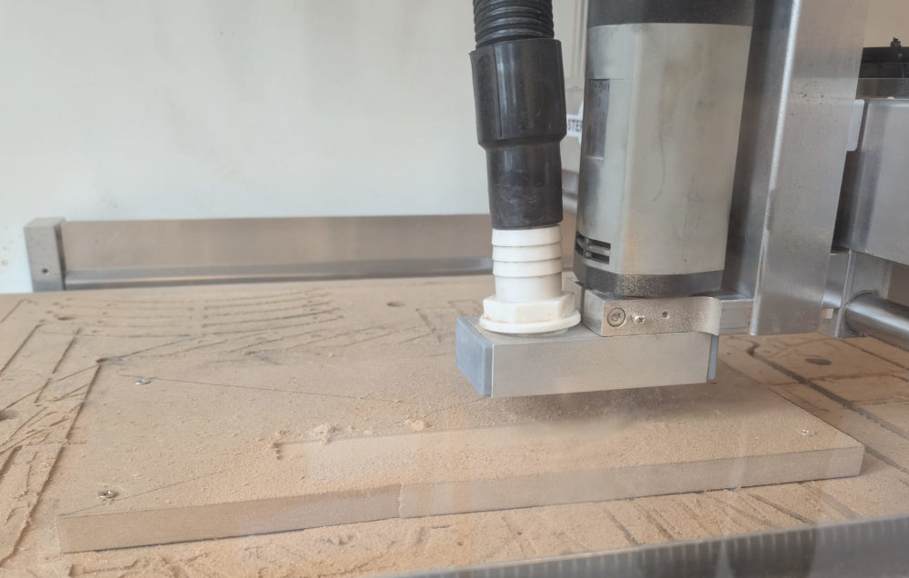
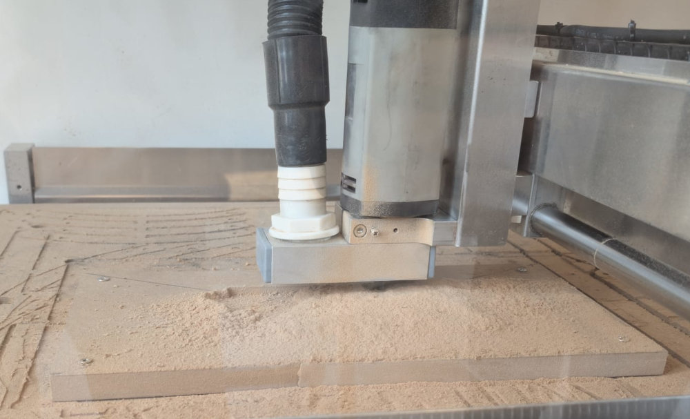
If I want, I can pause the manufacture and switch off the spindle to clean the wood dust with the vacuum cleaner.
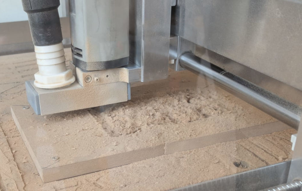
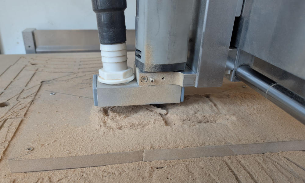
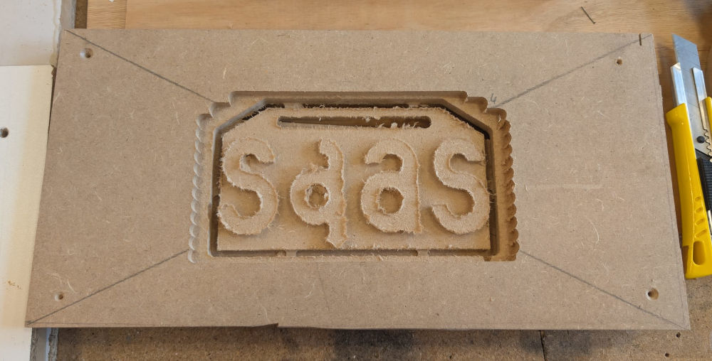
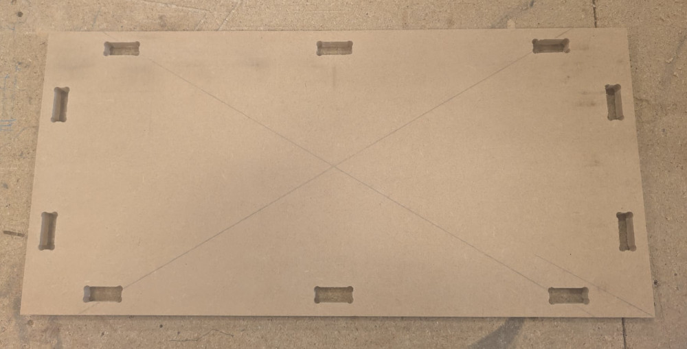
When the CNC is done, it will go to its machine origin. We can then clean with the vacuum cleaner and move the axes to safely remove the screws of the stock.
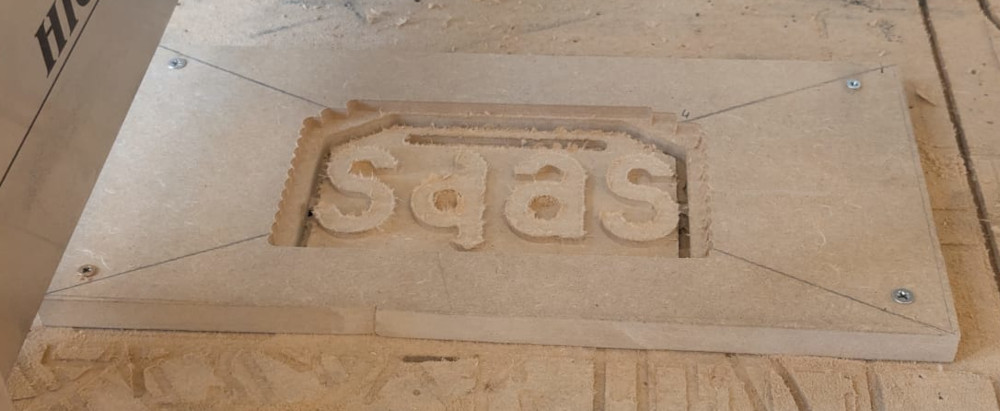
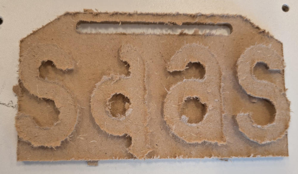
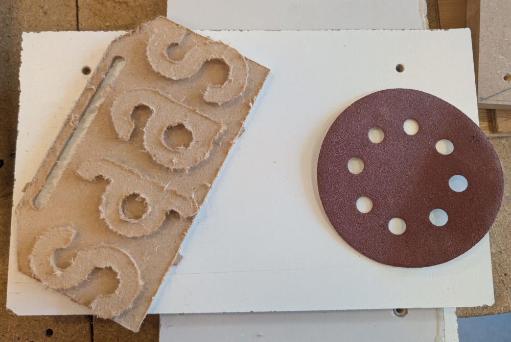
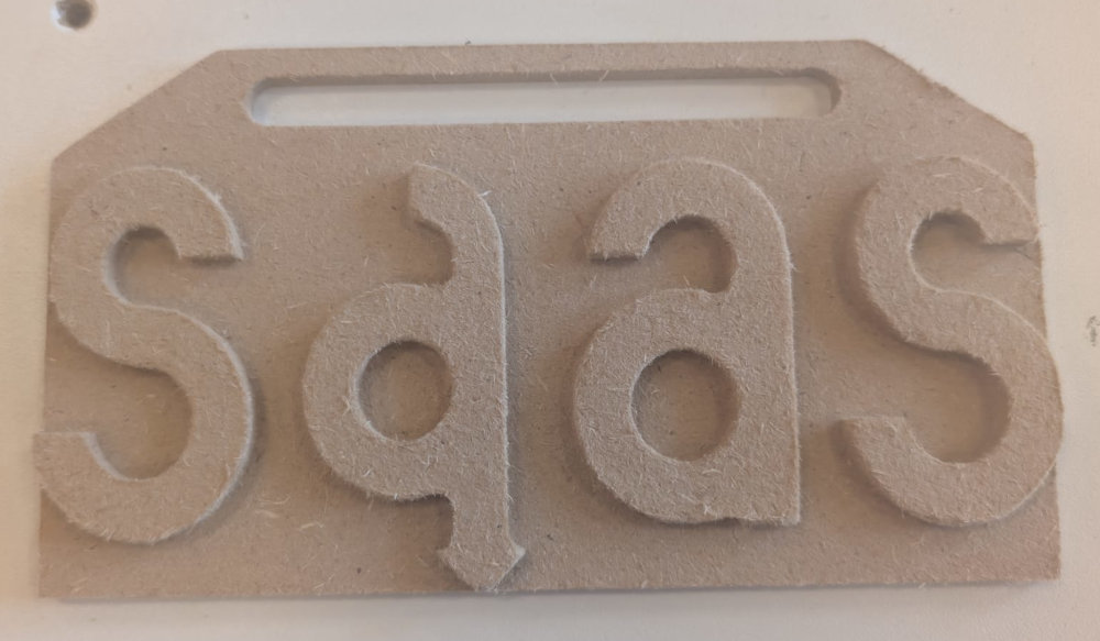
Finally, I just have to use a cutter to remove the tabs and then use sandpaper to remove the fuzz/wood fibers.
-
-
CNC tests
To test our CNC, we did brushes, kerfs and dogbones tests. The end mill used for these tests had a diameter of 6mm.
-
Brush
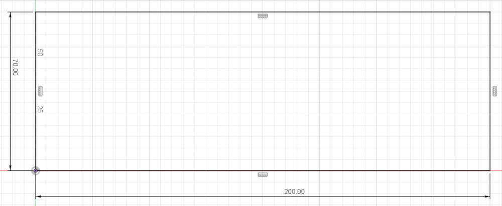
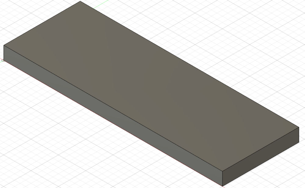
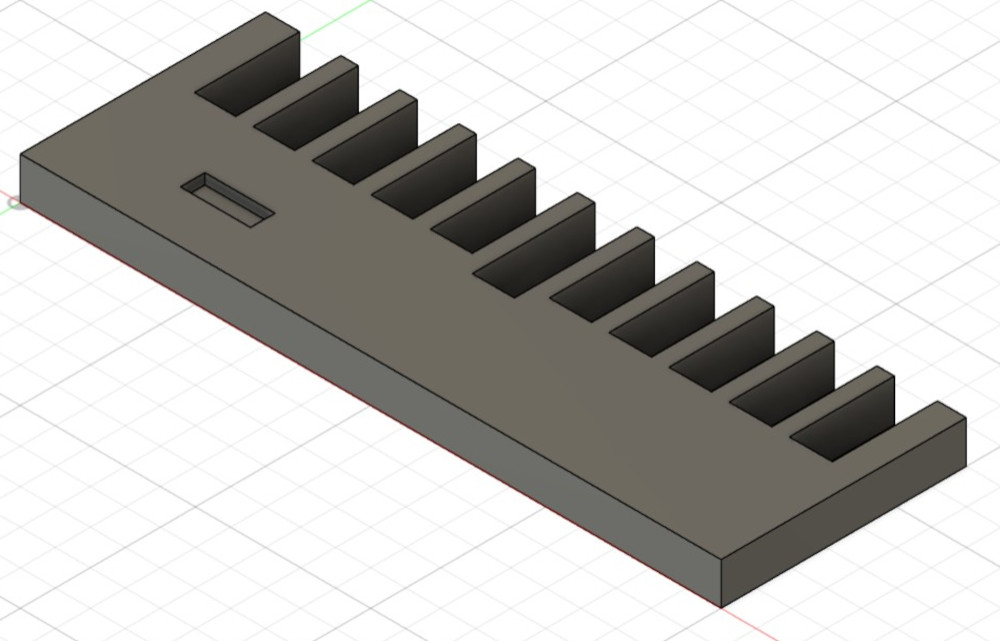
For the brush, I made a 3D model in Autodesk Fusion.
I start with the base :
Then add the holes for the brush test :
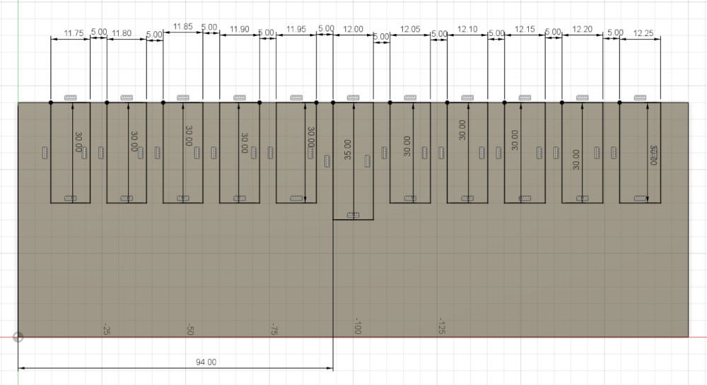
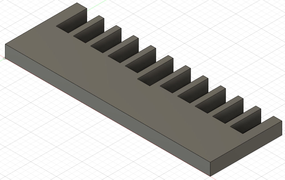
And finally, I had a little hole to mark which side has the tiniest holes :
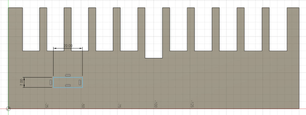
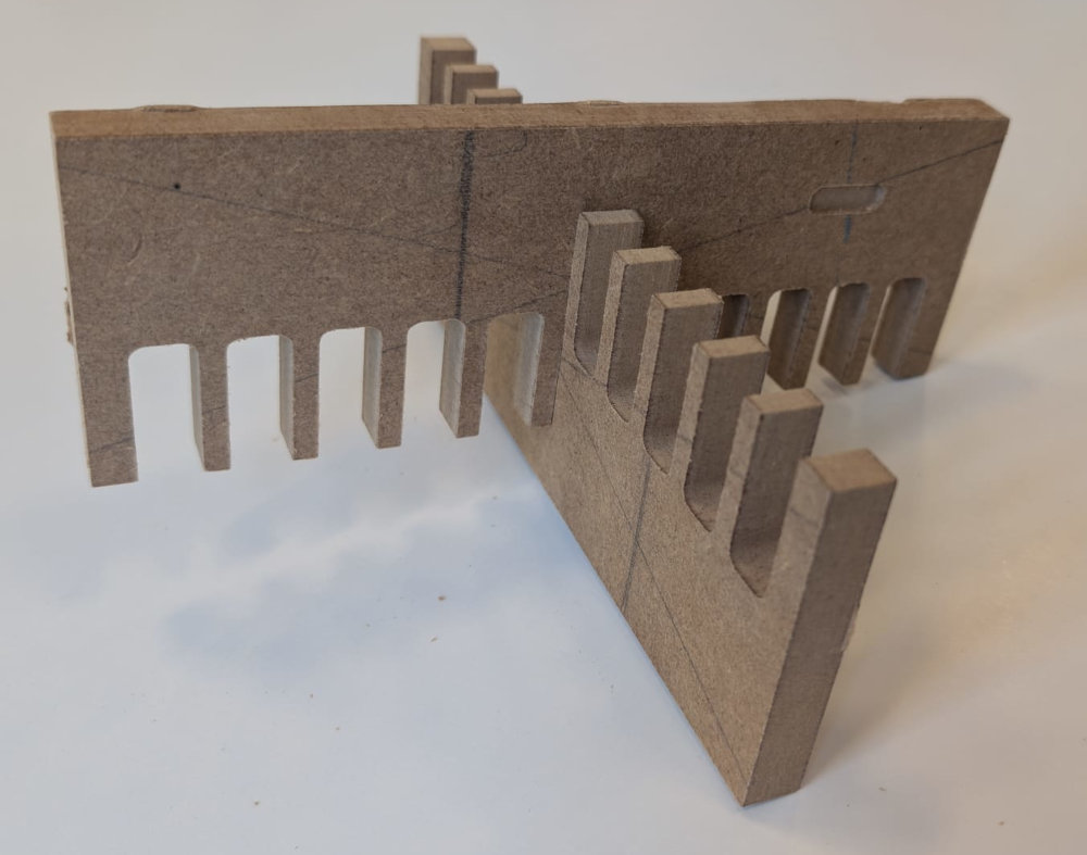
The distance for the middle hole was supposed to be 12mm but after using the CNC to mill the piece we can see that the real distance is 11.69mm.
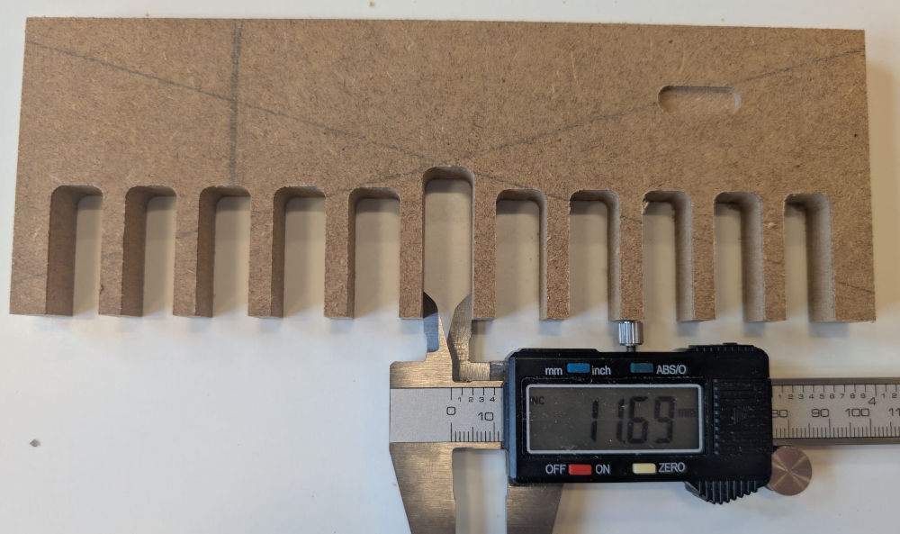
The brushes fit well just with the middle holes.
-
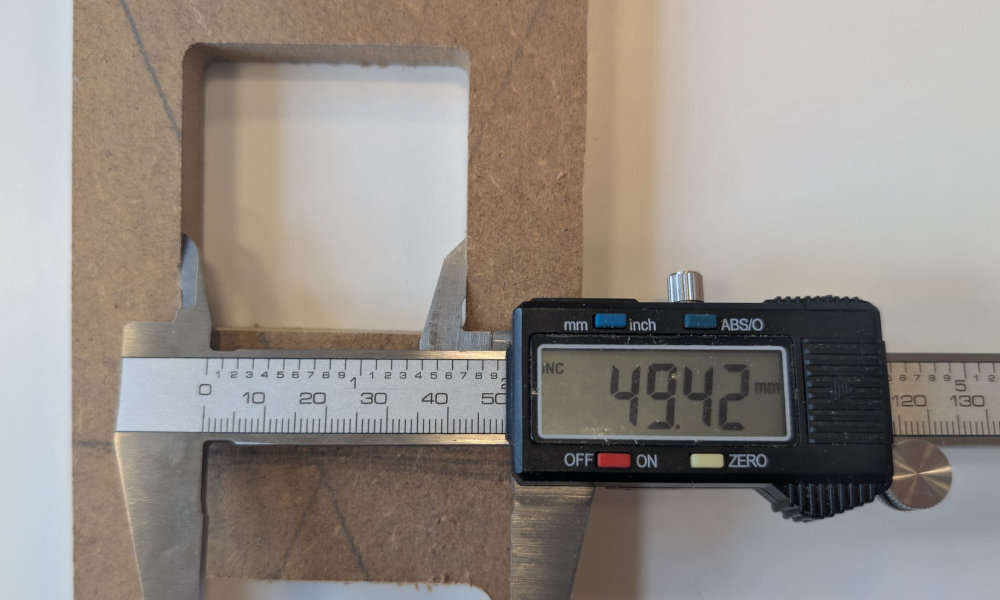
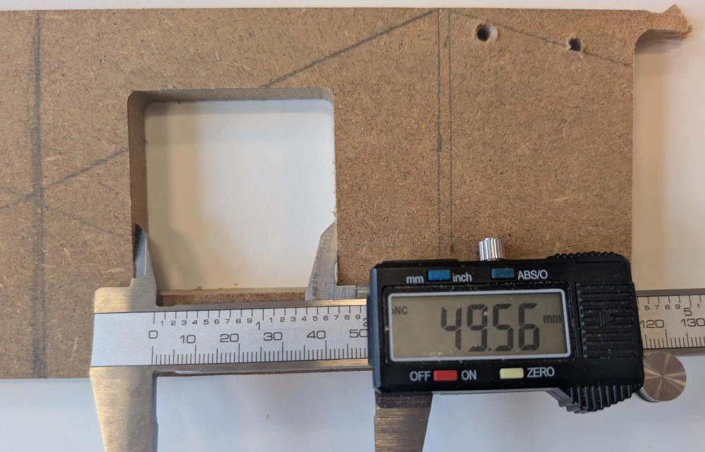
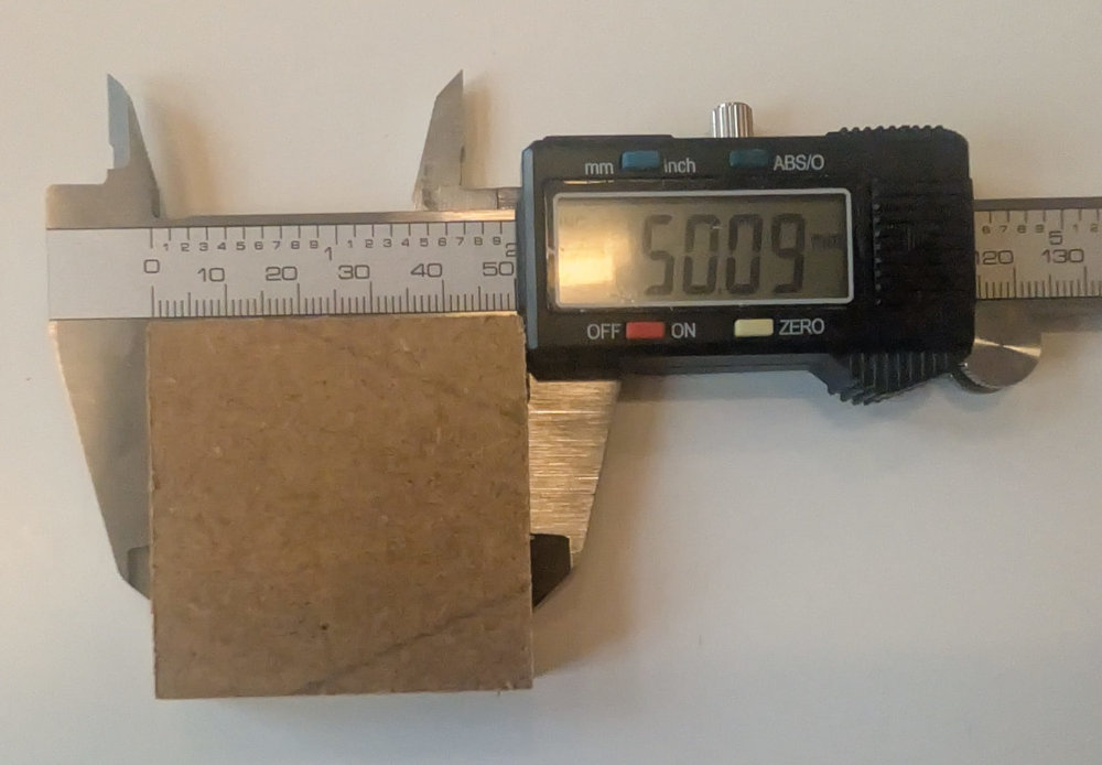
Kerf
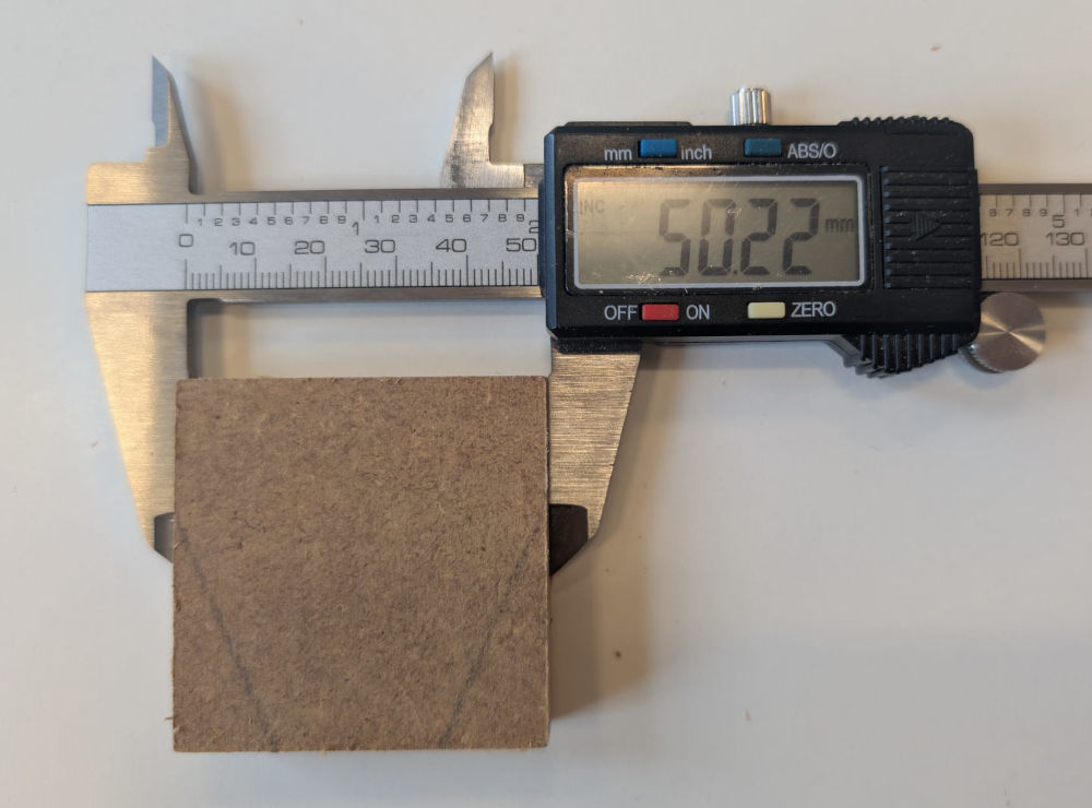
Jonas did the Kerf tests, he made 2 squares, one that can be taken off and one which is a hole, both 50mm².
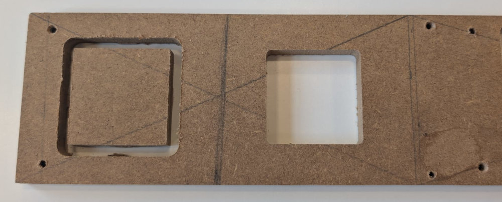
When measuring both, we can see the hole isn't exactly 50mm² while the square was close.
-
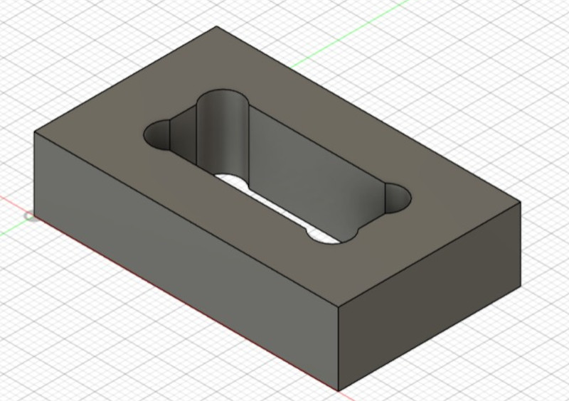
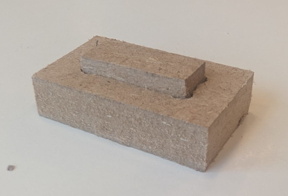
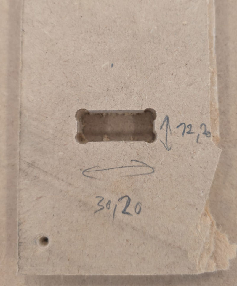
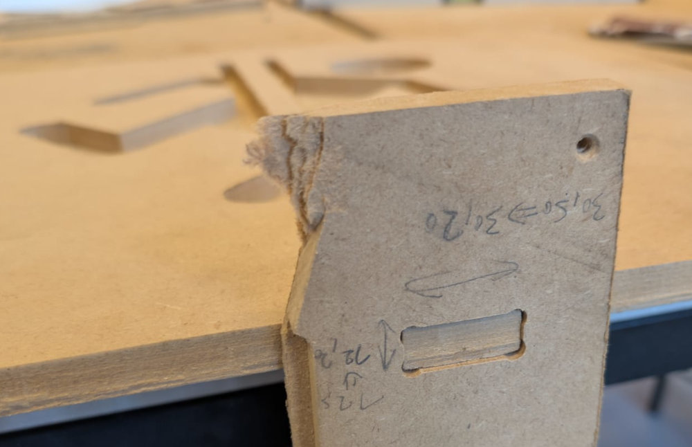
Dogbone
A dogbone is mainly used to assemble joints easily when rectangle shaped, I just add holes at the angles, like its name suggest, its looks like a bone.
I made a simple design in Autodesk Fusion as well a piece to fit.
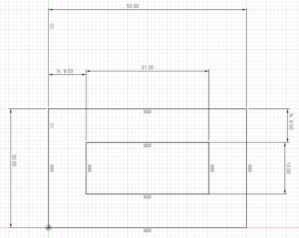
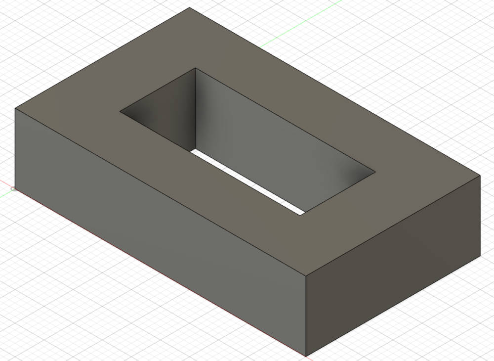
I start with the base and the inner hole :
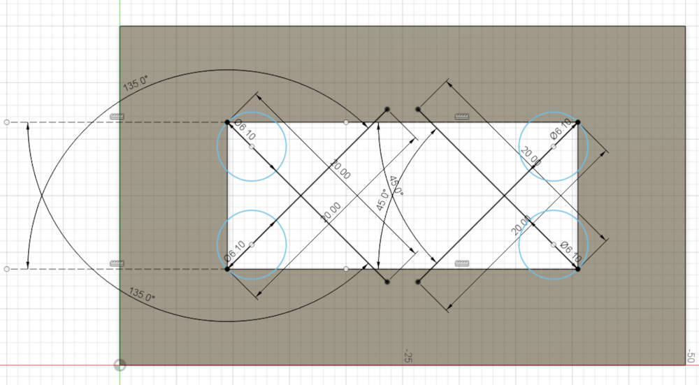
Then I make the dogbones holes myself :
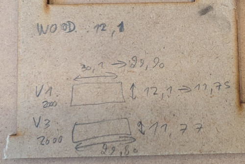
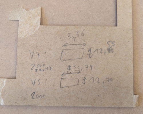
I had to do multiple test to find a good fit because I noticed that decreasing the speed of the axes of the CNC gives us better result that are closer to what I drew in the software.
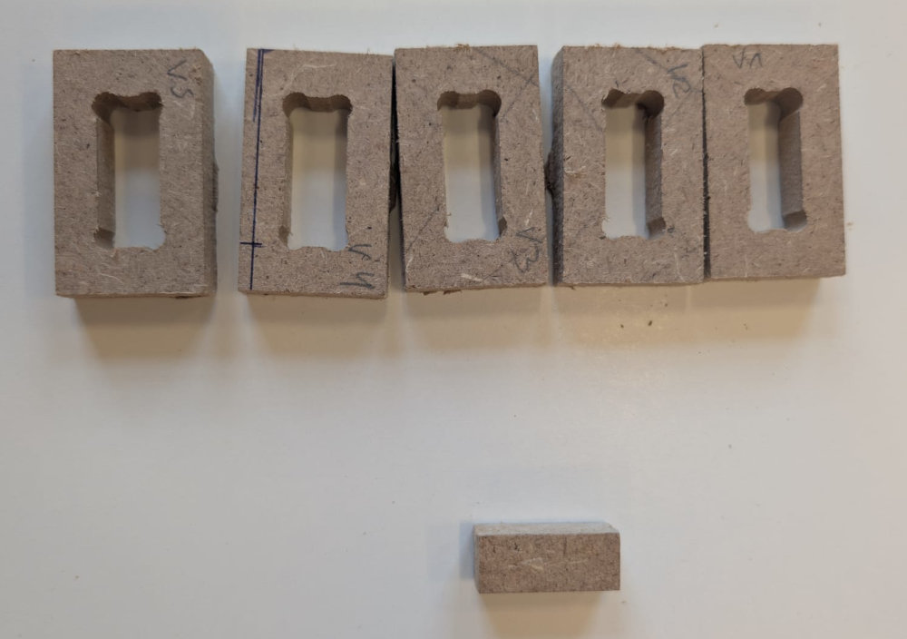
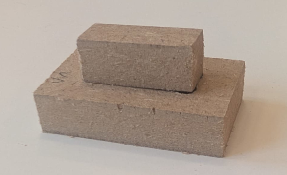
Final result :
-
-
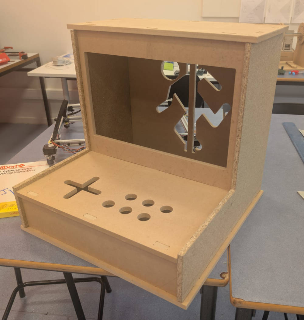
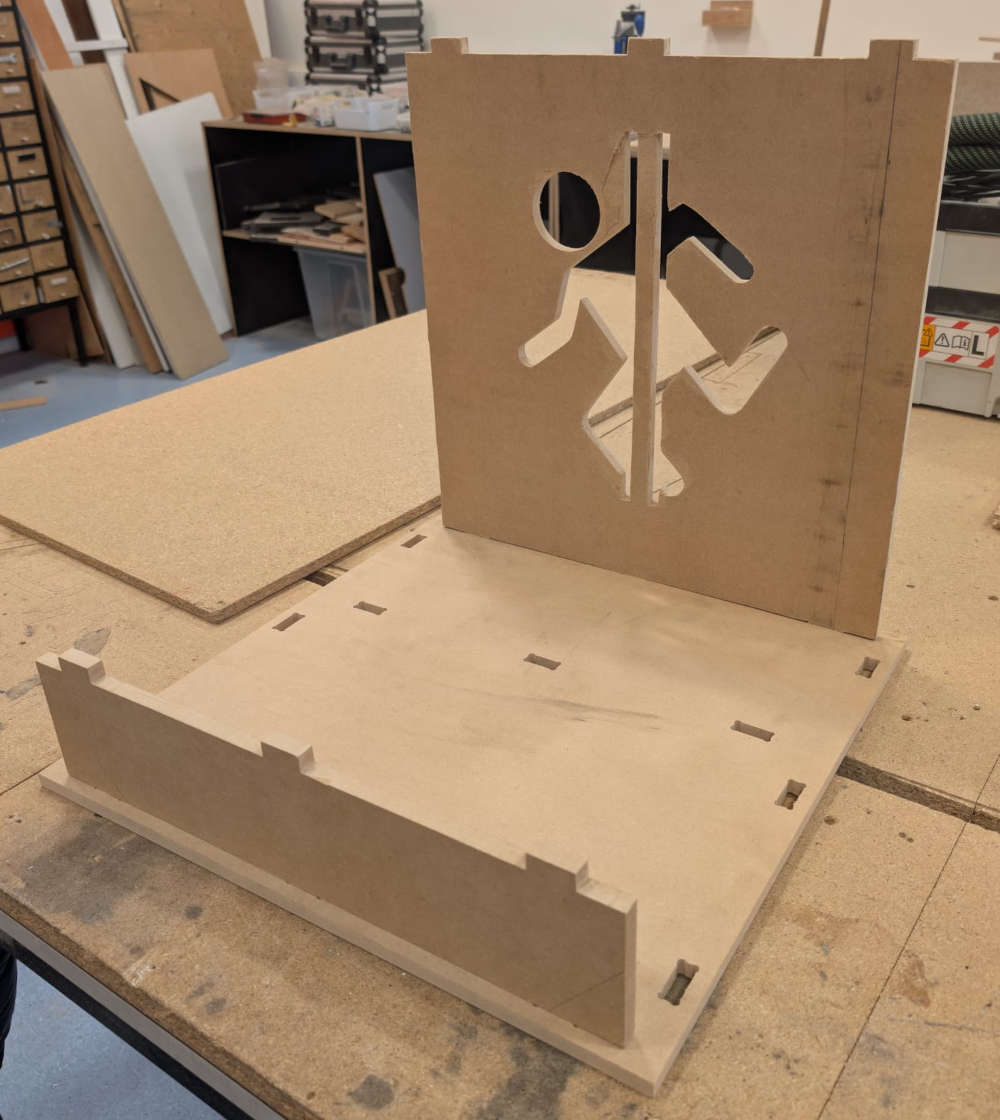
Personal assignment
For my personal assignment, my Fab Academy instructor, Patrick, gave me the idea to make the top of an arcade machine, to already have a start of how to build my final project.
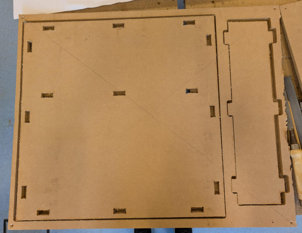
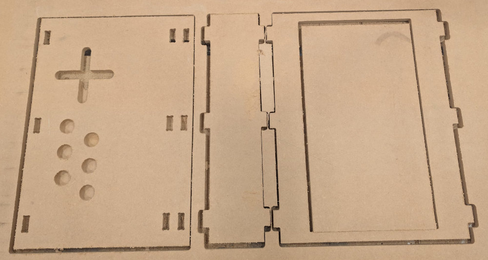
It took me a lot of time, but I made all the pieces in Autodesk Fusion and then assemble them to make sure everything fit together.
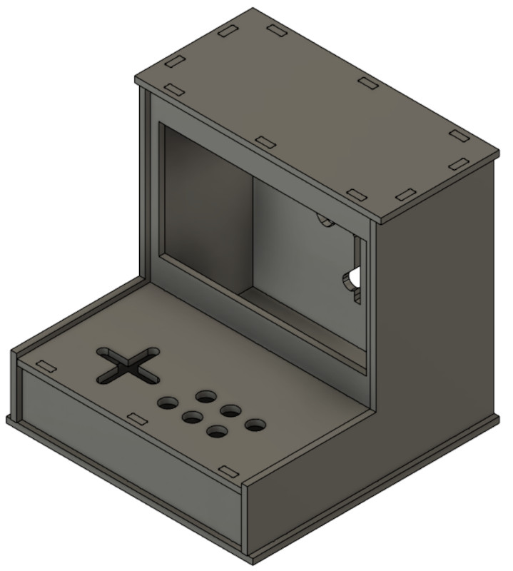
Then, by following the instructions from the previous chapters, I manufacture every pieces on the CNC.
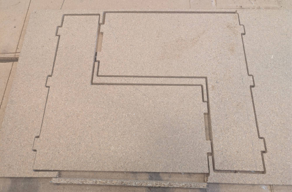
I first start with the back to have a starting point for measures.
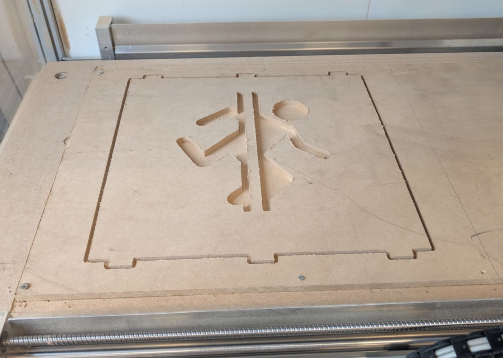
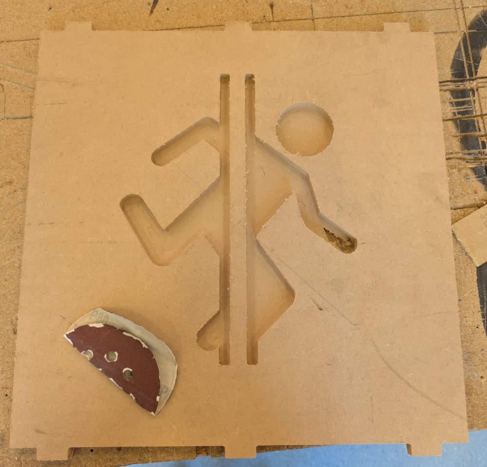
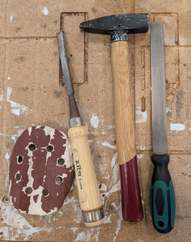
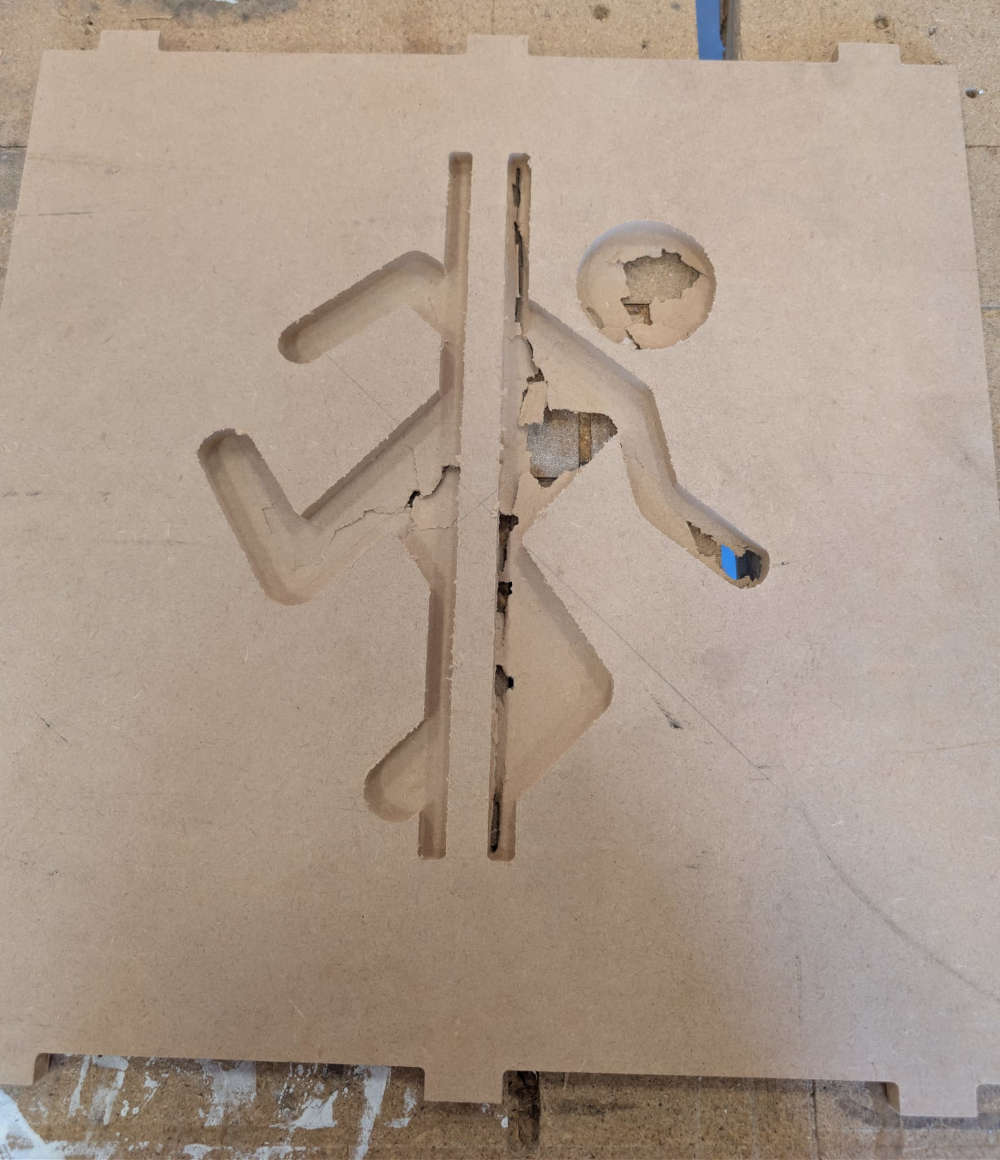
I notice the CNC didn't go all the way through so I have to take the excess stock by hand and with tools
Then, I do a dogbone test to see what dimensions and speed are the best for a good fit. Luckily, My first test was good enough. So, I modify all the dogbones of the 3D files to the good values.
Now that everything seems good, I manufacture every part.
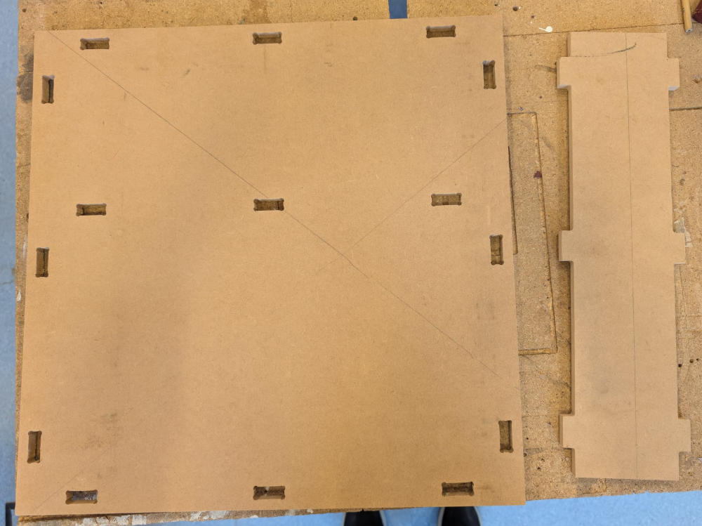
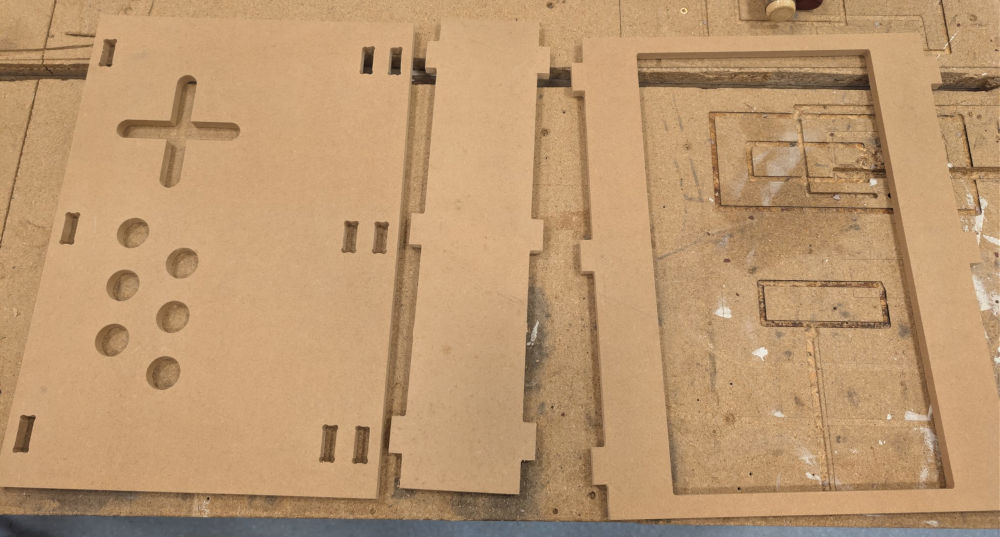
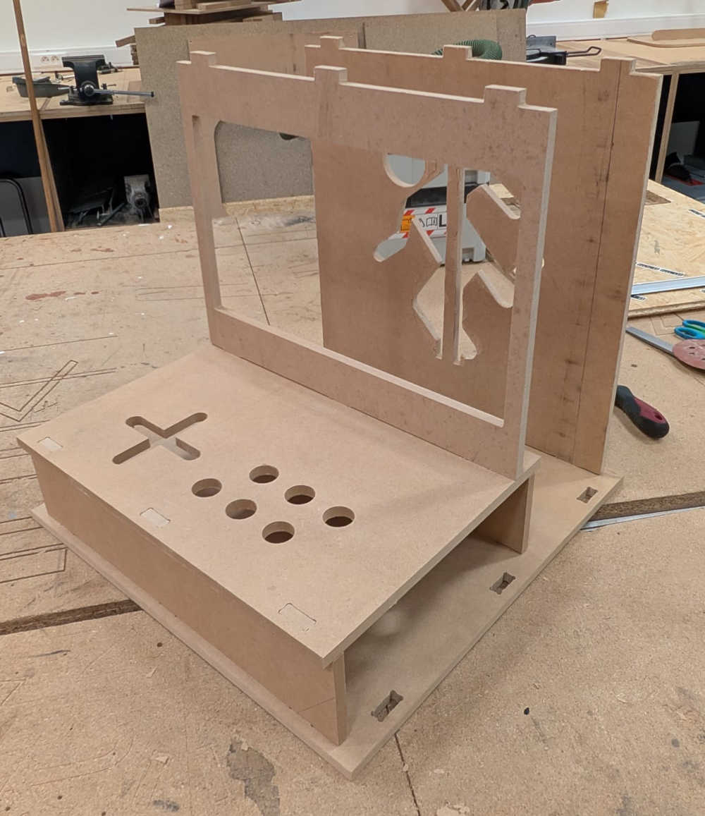
I ran out of the same wood so I had to use another type for the sides.
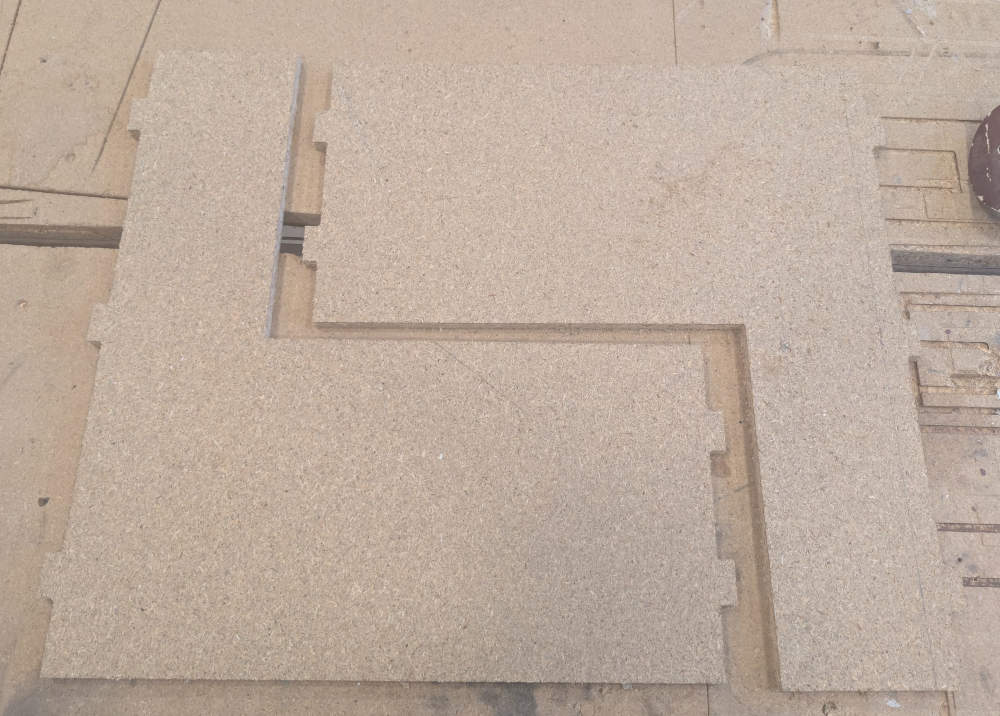
Here's the final result :
Problem(s) met
-
Windows and KinetiC-NC
When doing the formation test with the CNC for the first time, we had a problem and the Z axis had weird coordinates which led to the piece getting milled all the way through on the first function which gets rid of excess stock on the top when it only needed to remove 8 mm of stock.
The problem was linked to Windows and a new update from the previous software, KinetiC-NC.
We eventually switched to LinuxCNC which worked perfectly.
-
G-code
We had a problem when initializing the workpiece on LinuxCNC, when we opened the file in the software, it told us the origins were out of bounds, even though we had set them up moments before. The problem appears to be linked to the post processor.
We fixed this by removing 2 lines in the G-code in the beginning and the end : G53 G0 Z0.
Useful file(s) (Click to download)
- SAAS panel 3D file (Autodesk Fusion)
- SAAS panel G-code files (Original and modified) (Autodesk Fusion)
- LinuxCNC post processor file (Autodesk Fusion)
- CNC tests (Autodesk Fusion)
- Arcade CNC (Autodesk Fusion)
Assignments checklist
- ✅Linked to the group assignment page.
- ✅Reflected on your individual page what you learned of your labs safety training.
- ✅Documented how you designed your object and made your CAM-toolpath.
- ✅Documented how you milled and assembled your final product (including setting up the machine, fixturing, feeds, speeds etc.).
- ✅Described problems and how you fixed them.
- ✅Included your design files and hero shot of your final product.