Prior knowledge
|
I already tried multiple and different kinds of output devices and sensors in my life. |
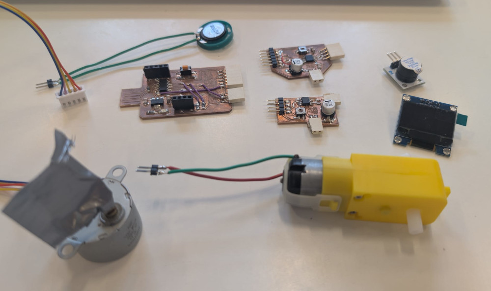
Hero shot
Making the PCBs
For this week, I'll test different kinds of outputs devices and sensors.
I will also work with a new microprocessor, the SAMD11C14. Compared to the SEEED XIAO RP2040 that I've already tried : it is tinier, has more GPIOs and can be flashed to interact with more easily in the future via USB.
Before making the PCB, I'll choose the devices I'll test to design my PCB according to them to know how many pins I need for this or that device. I want to try a servomotor, a DC motor, a step motor, a buzzer, a speaker and an OLED screen.
After thinking, I'll go with 3 connectors :
- One six pins connector for the DC and step motors, I decided to make my own motor driver PCBs for both motors and since they are similar in they way the work, I can combine them in a single connector.
- One 3 pins connector for simpler devices like the servomotor, the buzzer and the speaker.
- One 4 pins connector for I2C devices like the OLED screen.
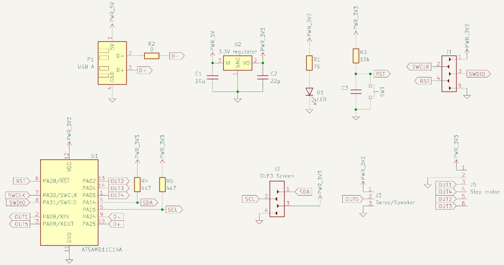
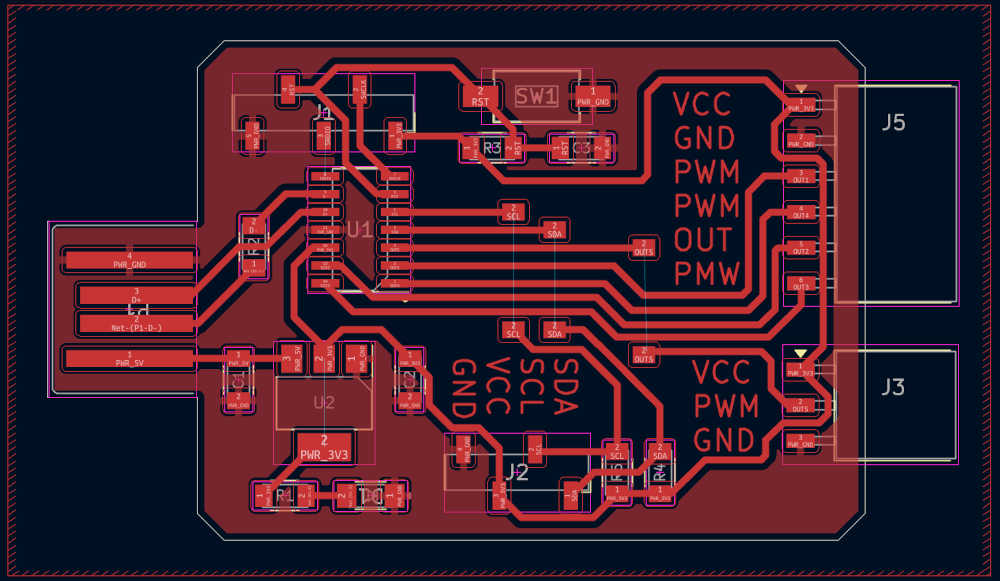
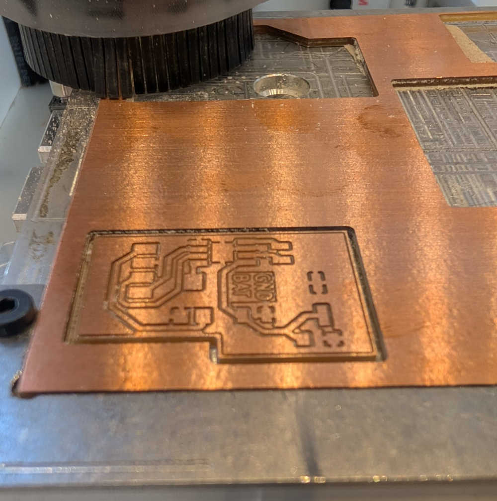
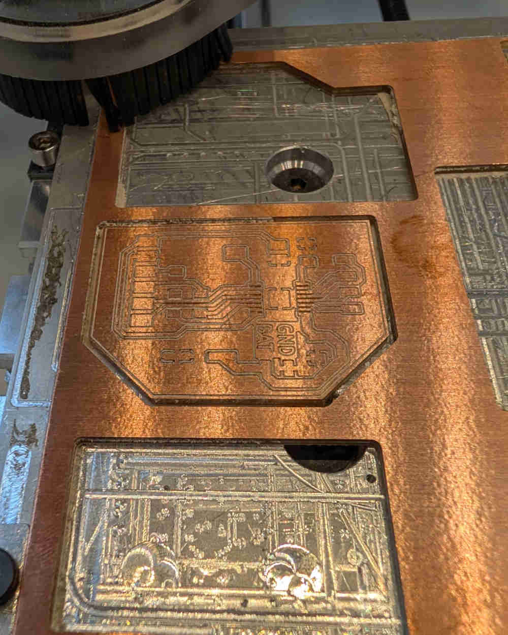
I use KiCad to make the designs and the Bantam PCB milling machine for the PCBs, here are the results :
-
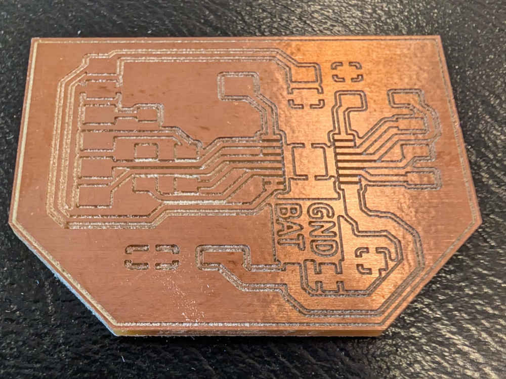
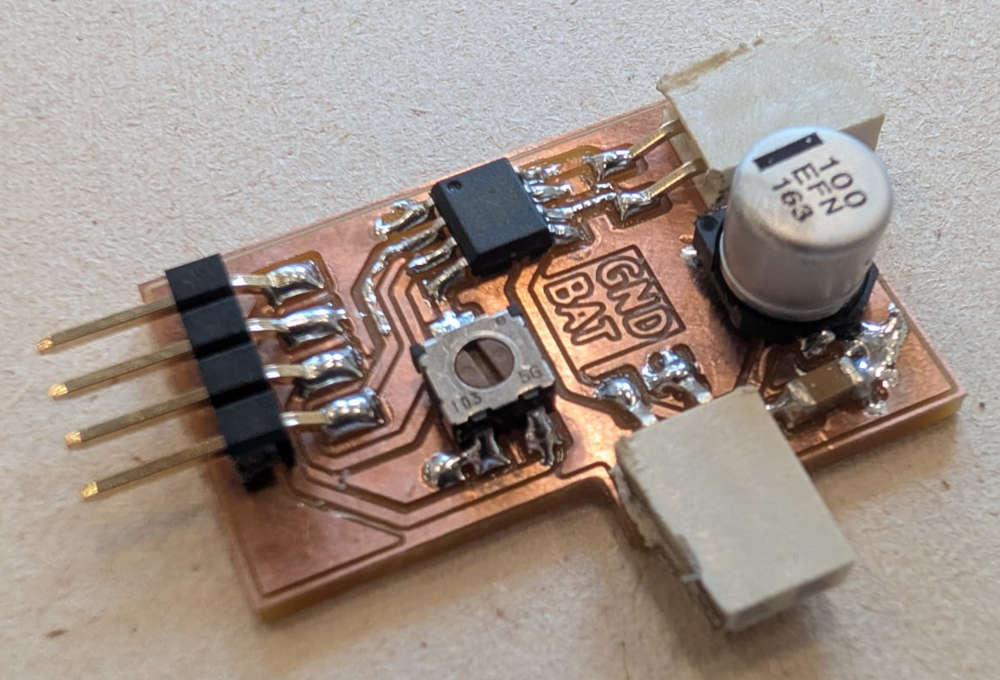
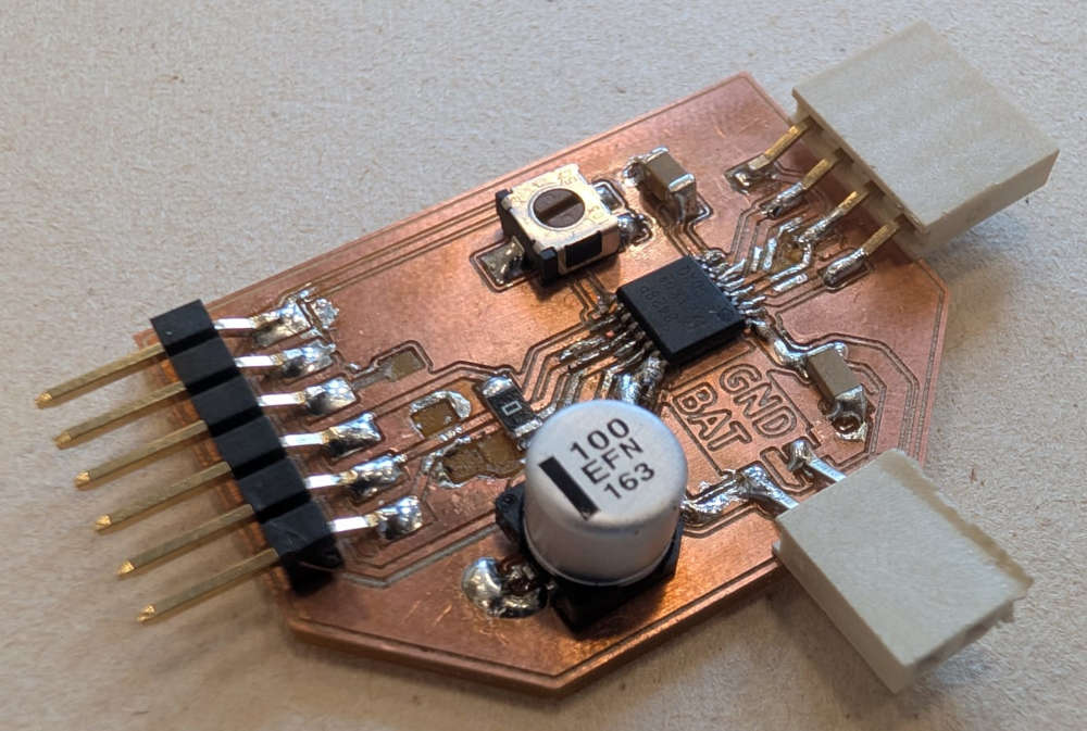
SAMD11C14A PCB
Some pins need to have specific functions like for the USB interface (PA24 and PA25), for the flashing (PA28, PA30 and PA31) and for I2C (PA14 and PA15).
The PCB was made with the help of Quentin BOLSEE's documentation and the Atmel SAM D11 datasheet (more specifically page 8 for the pinout, pages 13 and 14 for the GPIO functions, page 18 for the power supply circuit, page 912 for the reset circuit and page 920 for the USB interface).
I used a 0,3 mm end mill for the tracks and a 1 mm end mill for the edge cut.
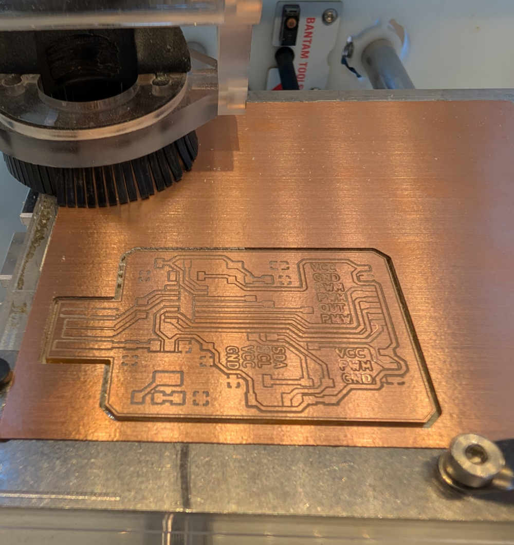
The milling looks a bit weird because I tried with a end mill that was a bit broken
-
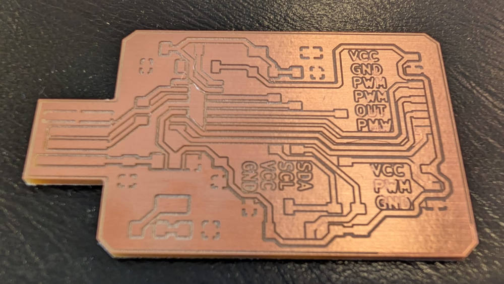
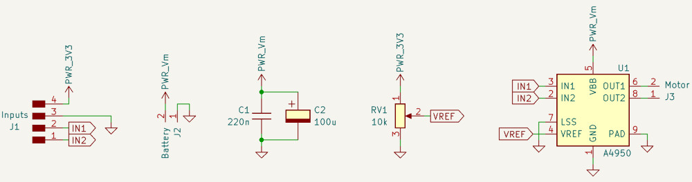
DC motor PCB
The PCB was made with the help of the datasheet of the A4950, a DC motor driver.
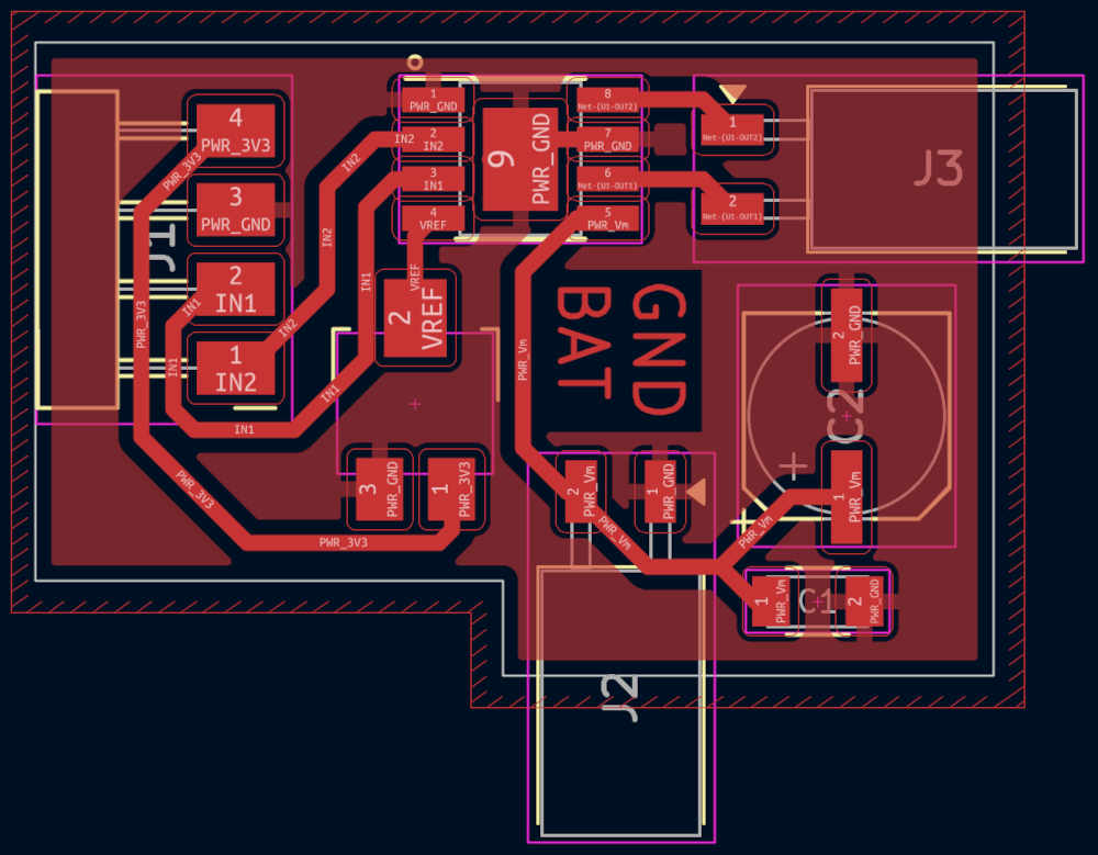
I used a 0,3 mm end mill for the tracks and a 1 mm end mill for the edge cut.
-
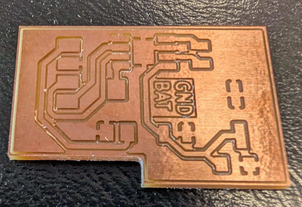
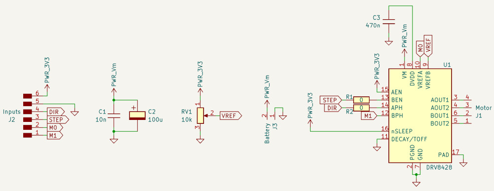
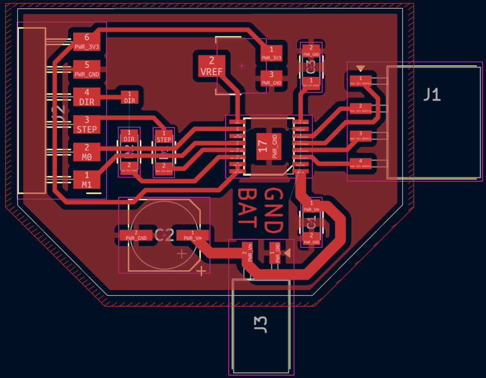
Step motor PCB
The PCB was made with the help of the datasheet of the DRV8428, a step motor driver.
I used a 0.005" V-shape end mill for the tracks and a 1 mm end mill for the edge cut.
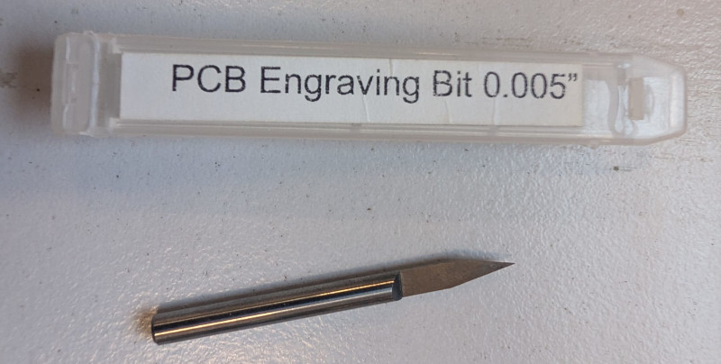
It was my first time using this end mill, I just used the default parameters, that's probably why the milling looks a bit weird.
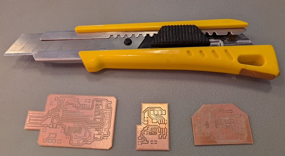
When all PCBs are made, I used a cutter to finish the tracks that didn't cut well and avoid short-circuits (mainly the SAMD11C14A PCB because of the broken end mill).
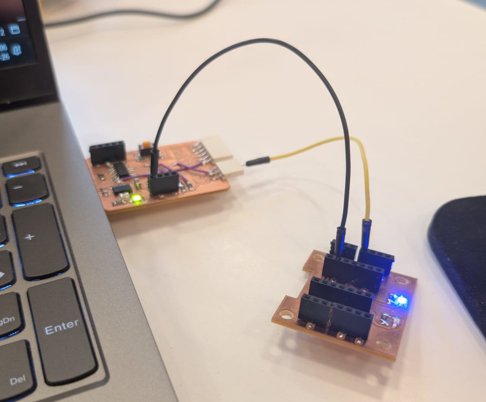
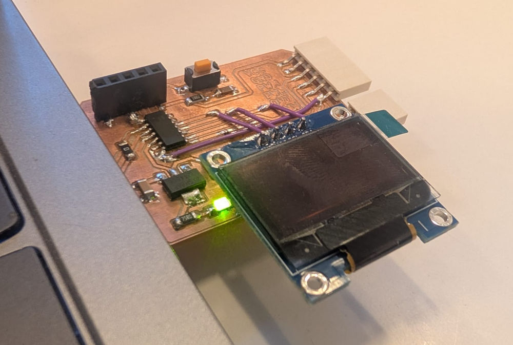
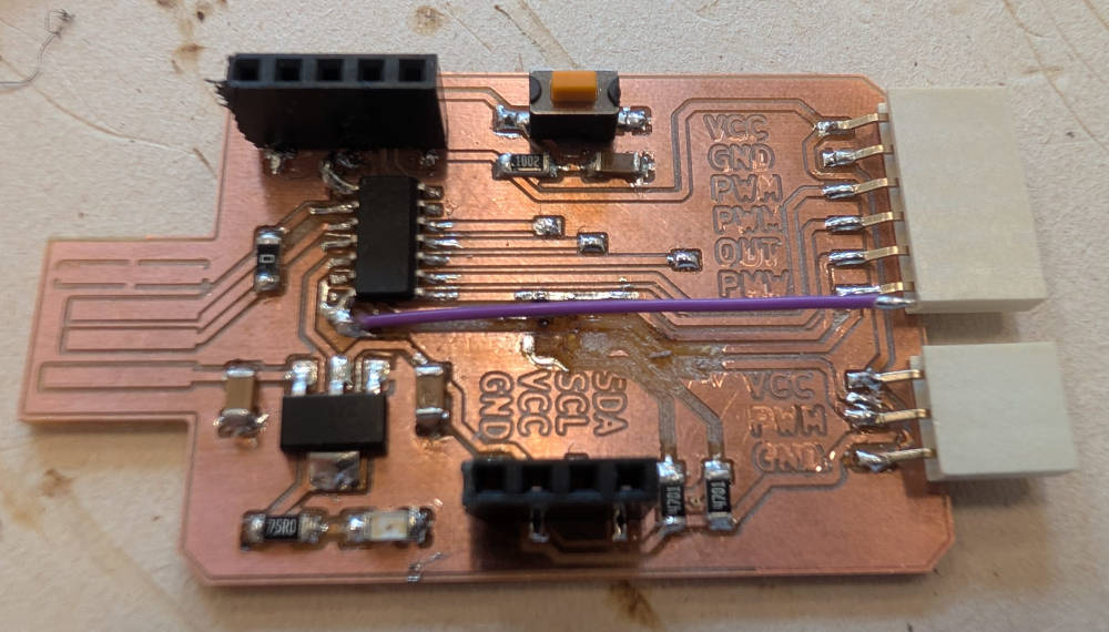
Then I solder everything :
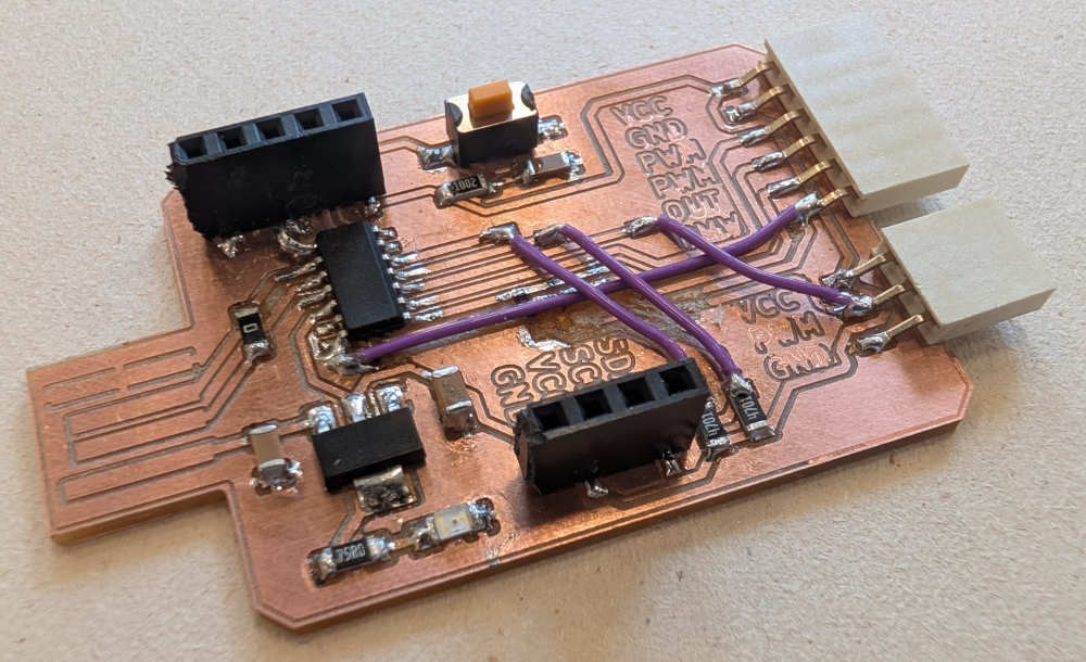
(The purple cables are explained in the Problem(s) met section.)
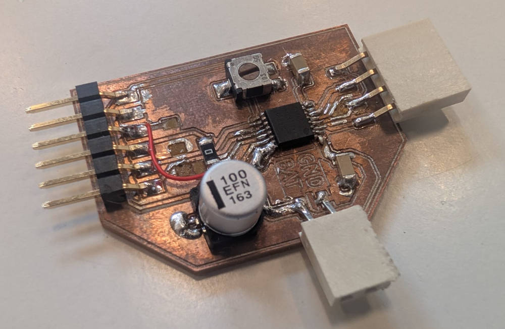
(The missing pads and tracks are explained in the Problem(s) met section.)
Flashing the microprocessor
Before coding, I need to flash a bootloader onto the microprocessor, again with the help of Quentin BOLSEE's documentation and ChatGPT, this can be done easily with the right material.
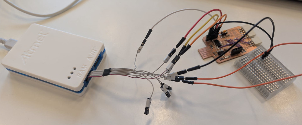
All I need is a debugger, in this case, I used the Atmel-ICE.
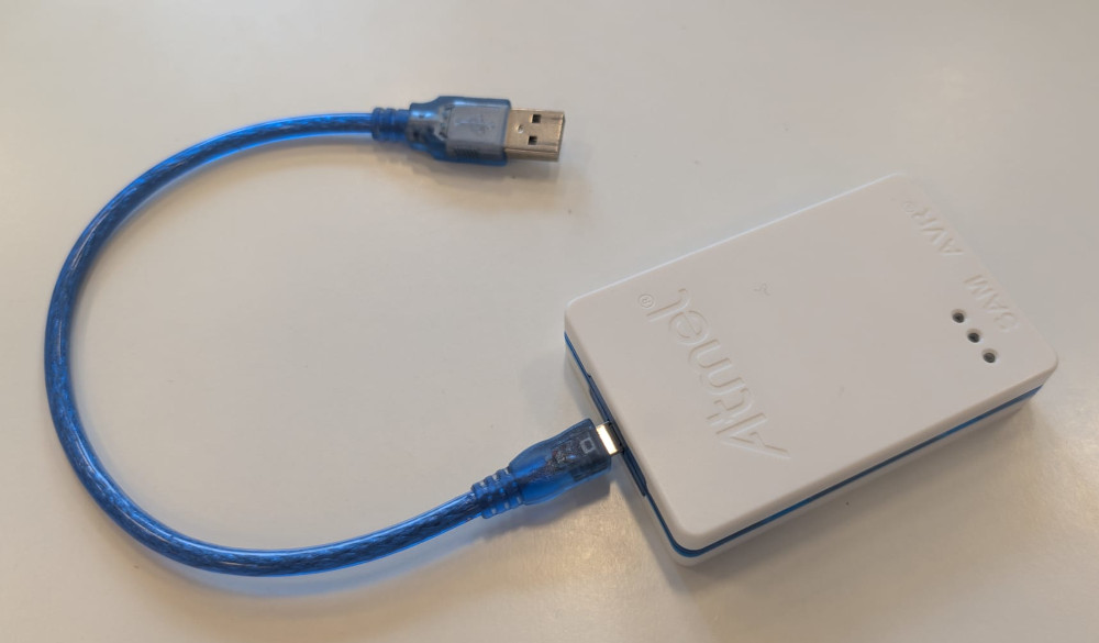
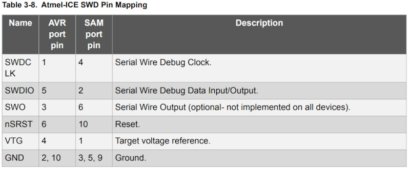
With the help of the Atmel-ICE's datasheet (more specifically page 15 for the right connector and page 22 for the SWD interface which our SAMD11C14A PCB uses for the flashing), I can easily connect the debugger to my main PCB.
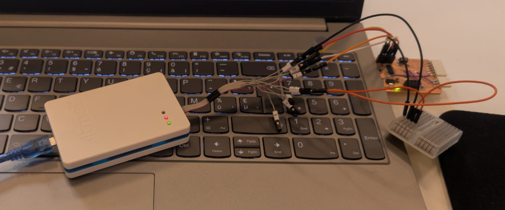
(Breadboard for the grounds)
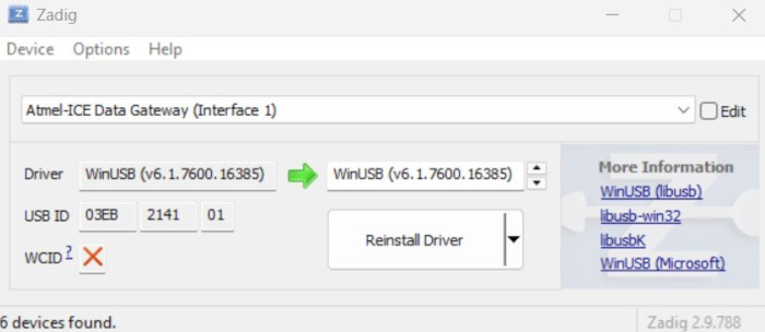
At first, the debugger wasn't recognized by my computer, so I needed to install the driver, I do this with Zadig.
I simply plug the debugger in my computer, the application will automatically detect it, I have to select Atmel-ICE in the dropdown list, select the desired driver, in this case WinUSB then press Install Driver (I already did it so it says Reinstall Driver).
Now that my computer detects the debugger, I can flash the bootloader in my microprocessor.
At this point, I simply follow Quentin's tutorial, I have to download a specific bootloader based on the core of my microprocessor for the Arduino as well as the latest version of an embedded debugger.
Then, from where the 2 downloaded files are located, I open a terminal window and enter the following line to flash my microprocessor :
edbg-windows-r74.exe -bpv -e -t samd11 -f sam_ba_Generic_D11C14A_SAMD11C14A.bin
This should be the final result :
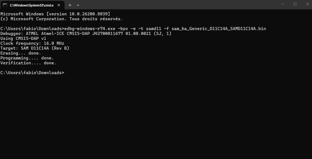
My PCB is now ready.
Codes
Before coding, I need to install the board's package because Arduino doesn't naturally support the SAMD11C14. At first I wanted to use the packages from the same creator of the bootloader, MattairTech, unfortunately, it seems these packages weren't available anymore, luckily and again, Quentin comes with the save with its own packages.
Now, in the Arduino IDE, i go to File, then select Preferences... and in Additional boards manager URLs, I add the following line :
https://raw.githubusercontent.com/qbolsee/ArduinoCore-fab-sam/master/json/package_Fab_SAM_index.json
Then on the BOARDS MANAGER tab, I type : Fab SAM, select the Fab SAM core for Arduino and click INSTALL.
My PCB is now ready and whenever I want to code, I can simply plug my PCB in a USB port and start coding, no need for the debugger anymore.
To make sure everything works, I try a simple led blinking code which works well.
-
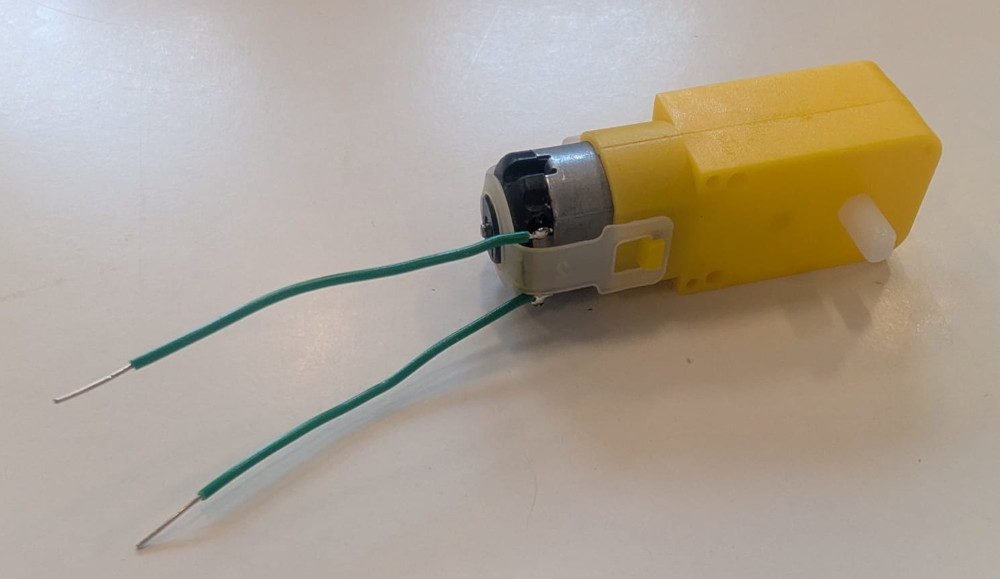
DC motor
Simple DC motor that was bought on Amazon with integrated reducers.
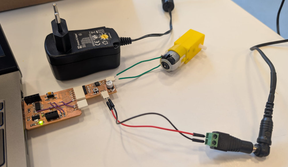
///////////////////////////////////// //////////// Code in C++ //////////// ///////////////////////////////////// // Motor pins #define IN1 8 // Pin PA08 of the SAMD11C14A #define IN2 5 // Pin PA05 of the SAMD11C14A void setup() { pinMode(IN1, OUTPUT); // Sets the IN1 pin as an output pinMode(IN2, OUTPUT); // Sets the IN2 pin as an output } void loop() { // Rotate forward analogWrite(IN1, 100); // Sets the speed at 100 (between 0(min) and 255(max)) analogWrite(IN2, 0); // Sets the speed at 0 delay(1000); // Delay of 1000ms // Stop analogWrite(IN1, 0); analogWrite(IN2, 0); delay(1000); // Rotate backward analogWrite(IN1, 0); analogWrite(IN2, 100); delay(1000); // Stop analogWrite(IN1, 0); analogWrite(IN2, 0); delay(500); } -
Step motor
Simple and classic step motor that I bought years ago and never used.
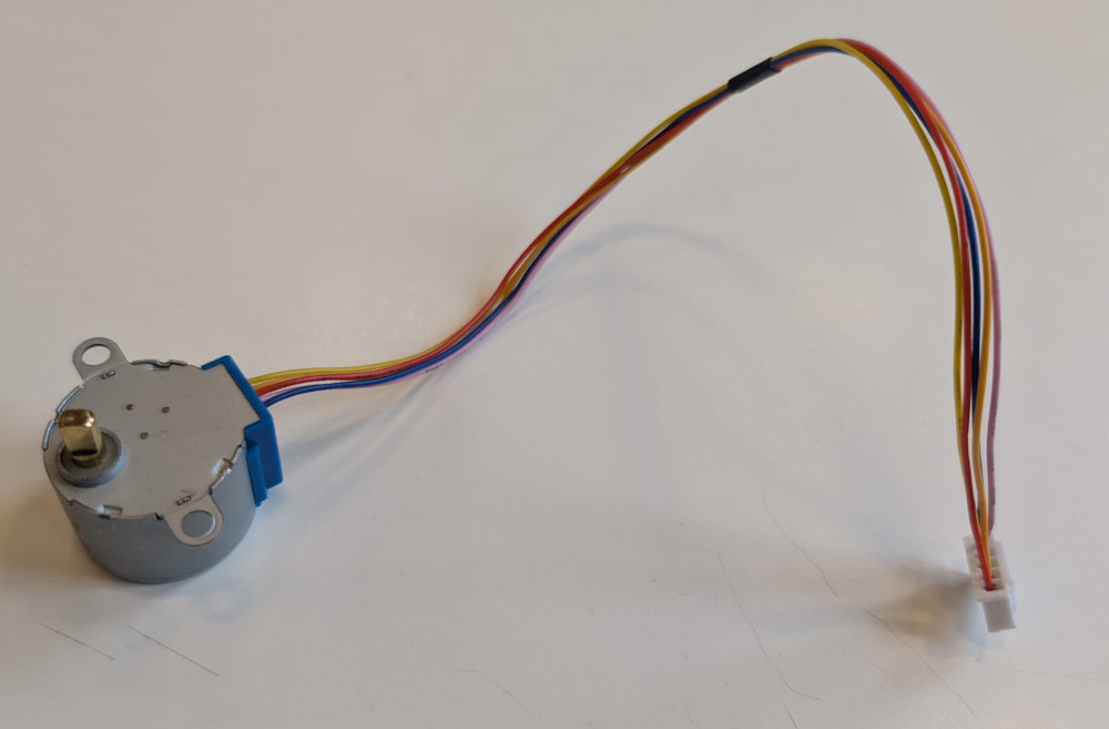
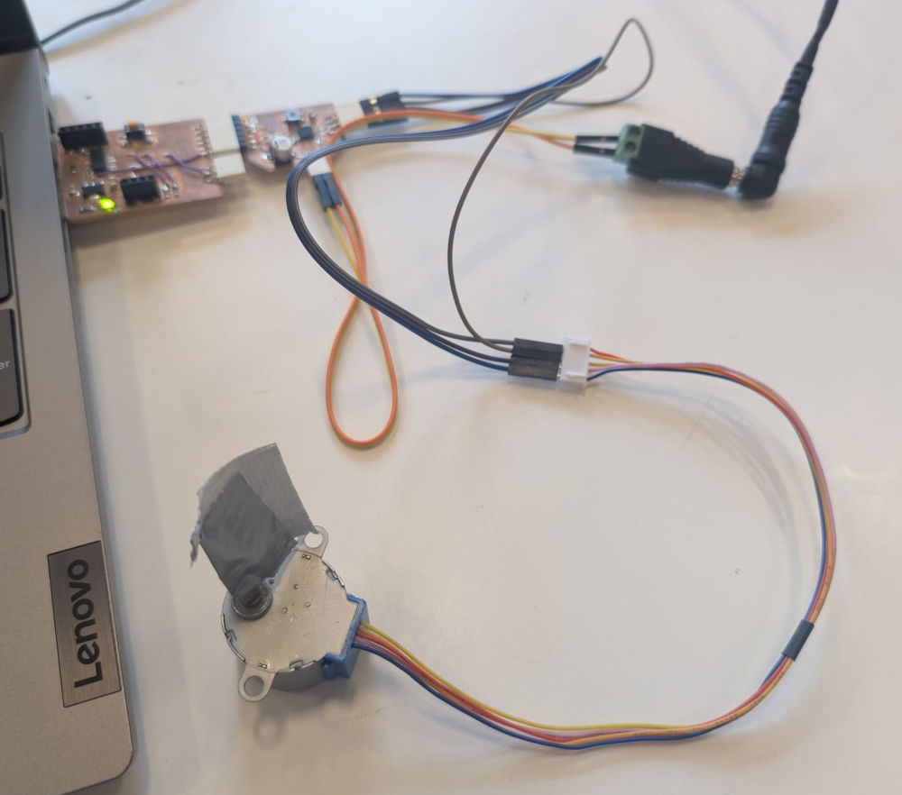
Unfortunately, I wasn't able to make it work and I'm not really sure where the problem is.
-
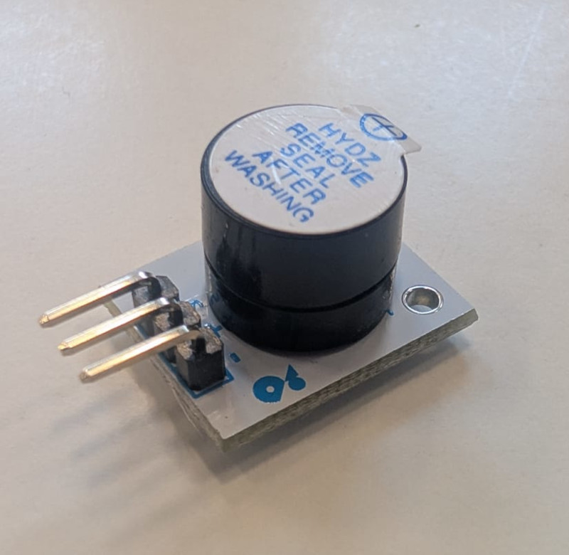
Buzzer
It is the VMA319 by Velleman, it is an active module, which means I cannot control the noise level, it is fixed by the manufacturer.
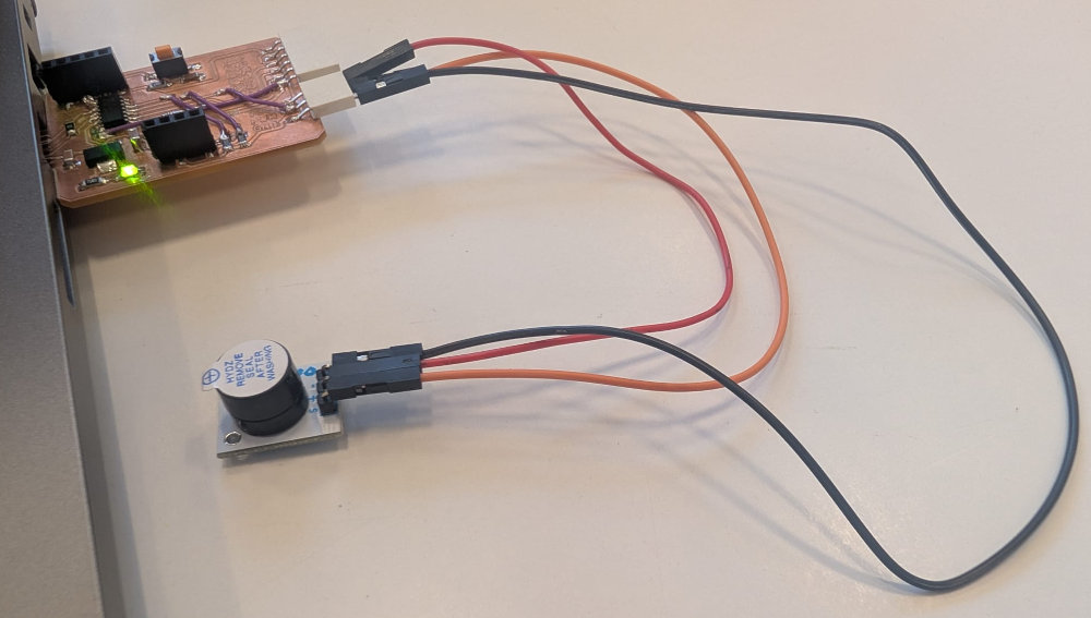
///////////////////////////////////// //////////// Code in C++ //////////// ///////////////////////////////////// // Buzzer pin #define Buzzer 9 // Pin PA09 of the SAMD11C14A void setup() { pinMode(Buzzer, OUTPUT); // Sets the buzzer pin as an output } void loop() { digitalWrite(Buzzer, HIGH); // Sets its value at 3.3V delay(1000); // Delay of 1000ms digitalWrite(Buzzer, LOW); // Sets its value at 0V delay(1000); } -
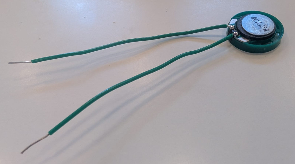
Speaker
Speaker from the FabAcademy inventory : PSR-23F08S-JQ.
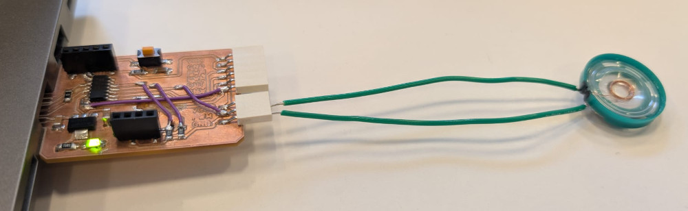
///////////////////////////////////// //////////// Code in C++ //////////// ///////////////////////////////////// // Speaker pin #define Speaker 9 // Pin PA09 of the SAMD11C14A void setup() { pinMode(Speaker, OUTPUT); // Sets the speaker pin as an output } void loop() { for (int i = 1000; i <= 6000; i += 1000) { tone(Speaker, i); // Turns ON speaker at a specific frequency (between 1000Hz and 6000Hz) delay(500); // Delay of 500ms } noTone(Speaker); // Turns speaker off delay(500); } -
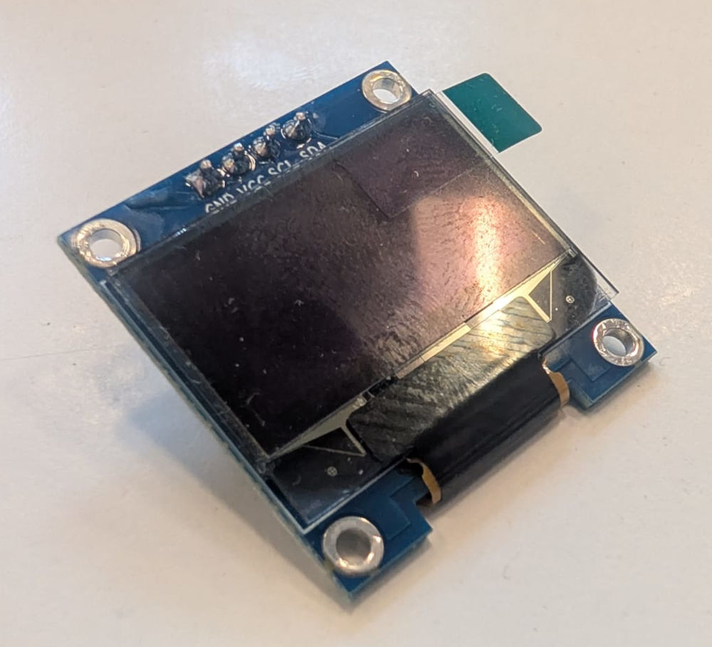
OLED screen
OLED screen from the FabAcademy inventory.
I've had a lot of problems trying to configure it with my PCB, I first used Quentin BOLSEE's QPAD display test code but I came up with compatibility problems with the board package of the SAMD11C14A and the SPI, I ask ChatGPT and copy the error messages and it guides me first to a different library to control the OLED screen without using SPI but the code was exceeding the flash memory so ultimately, ChatGPT gave me a code to write directly in I2C which kinda worked but the final result looked weird.
I came to the conclusion that the SAMD11C14A and the OLED screen were not fully compatible or at least it needed a bit more work.
                                        #include <Wire.h>

                                        #define OLED_ADDR 0x3C

                                        void cmd(uint8_t c) {
                                            Wire.beginTransmission(OLED_ADDR);
                                            Wire.write(0x00);  // command mode
                                            Wire.write(c);
                                            Wire.endTransmission();
                                        }

                                        void initOLED() {
                                            cmd(0xAE);  // display off
                                            cmd(0xA8);
                                            cmd(0x3F);  // multiplex
                                            cmd(0xD3);
                                            cmd(0x00);  // offset
                                            cmd(0x40);  // start line
                                            cmd(0xA1);  // segment remap
                                            cmd(0xC8);  // COM scan dec
                                            cmd(0xDA);
                                            cmd(0x12);
                                            cmd(0x81);
                                            cmd(0x7F);
                                            cmd(0xA4);
                                            cmd(0xA6);
                                            cmd(0xD5);
                                            cmd(0x80);
                                            cmd(0x8D);
                                            cmd(0x14);
                                            cmd(0xAF);  // display ON
                                        }

                                        void clearOLED() {
                                            for (int page = 0; page < 8; page++) {
                                                cmd(0xB0 + page);
                                                cmd(0x00);
                                                cmd(0x10);

                                                Wire.beginTransmission(OLED_ADDR);
                                                Wire.write(0x40);  // data mode
                                                for (int i = 0; i < 128; i++) {
                                                    Wire.write(0x00);
                                                }
                                                Wire.endTransmission();
                                            }
                                        }

                                        void drawHello() {
                                            // very small "Hello" pattern (hardcoded, saves memory)
                                            const uint8_t text[] = {
                                                0x7F, 0x08, 0x08, 0x08, 0x7F,  // H
                                                0x00,
                                                0x3E, 0x49, 0x49, 0x49, 0x26,  // e
                                                0x00,
                                                0x7F, 0x40, 0x40, 0x40, 0x40,  // l
                                                0x00,
                                                0x7F, 0x40, 0x40, 0x40, 0x40,  // l
                                                0x00,
                                                0x3E, 0x41, 0x41, 0x41, 0x3E  // o
                                            };

                                            cmd(0xB3);  // page
                                            cmd(0x20);  // column low
                                            cmd(0x10);  // column high

                                            Wire.beginTransmission(OLED_ADDR);
                                            Wire.write(0x40);
                                            for (unsigned int i = 0; i < sizeof(text); i++) {
                                                Wire.write(text[i]);
                                            }
                                            Wire.endTransmission();
                                        }

                                        void setup() {
                                            Wire.begin();
                                            initOLED();
                                            clearOLED();
                                            drawHello();
                                        }

                                        void loop() {
                                        }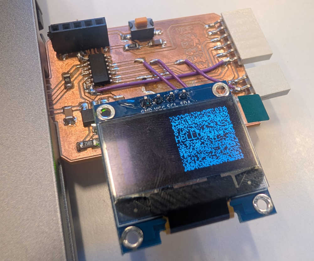
Problem(s) met
-
Soldering
Since some of these components are really small, mainly the step motor driver,the DRV8428 , which has really tiny pads, soldering was sometimes annoying and hard, I even accidentally took some pads and tracks off while trying to remove solder. So in some case, I'll need to use wires.
The step motor PCB is actually unusable because some of the grounds pins are not connected to the ground plane and I'll need better tools and thinner cables for these connection.
-
Atmel-ICE
At first the debugger didn't turn on, I later realized it was because of the USB cable used which didn't transmit power or data, which is weird because it was Michel's USB cable and it works for him and his microcontroller. I used another one and I could then use the debugger.
 <
<(You can see that none of the LEDs turn on)
-
SAMD11C14A board
I don't know why but after some tests, my PCB wasn't recognized anymore by my computer, I had to flash the bootloader onto the microprocessor again to make it work.
Useful file(s) (Click to download)
- SAMD11C14A PCB (KiCad)
- DC motor PCB (KiCad)
- Step motor PCB (KiCad)
- Flashing files (Command Prompt)
- DC motor C++ code (Arduino IDE)
- Step motor C++ code (Arduino IDE)
- Buzzer C++ code (Arduino IDE)
- Speaker C++ code (Arduino IDE)
- OLED screen C++ code (Arduino IDE)
Assignments checklist
- ✅Linked to the group assignment page.
- ✅Documented how you determined power consumption of an output device with your group.
- ✅Documented what you learned from interfacing output device(s) to microcontroller and controlling the device(s).
- ✅Linked to the board you made in a previous assignment or documented your design and fabrication process if you made a new board.
- ✅Explained how your code works.
- ✅Explained any problems you encountered and how you fixed them.
- ✅Included original source code and any new design files.
- ✅Included a hero shot of your board.