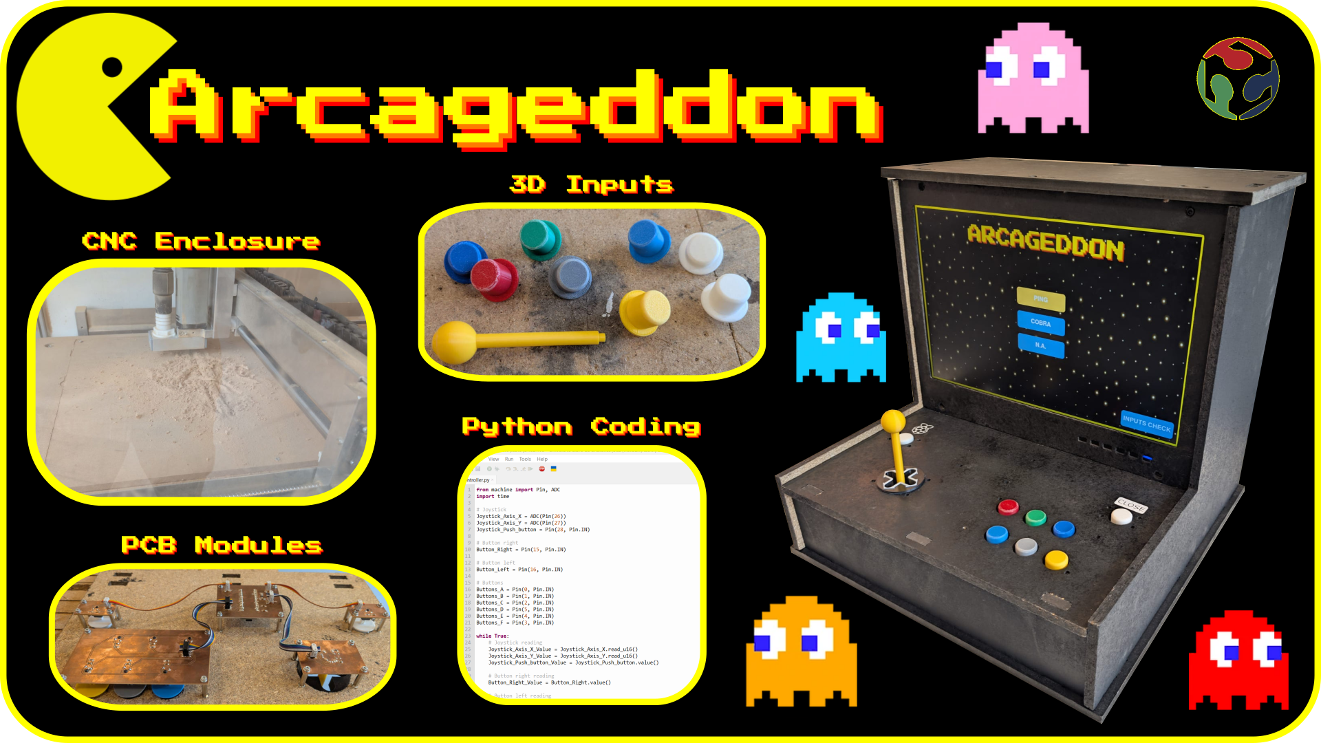
First idea and explanation
If you read the section of what I like, you can see I really like video games ever since I was young.
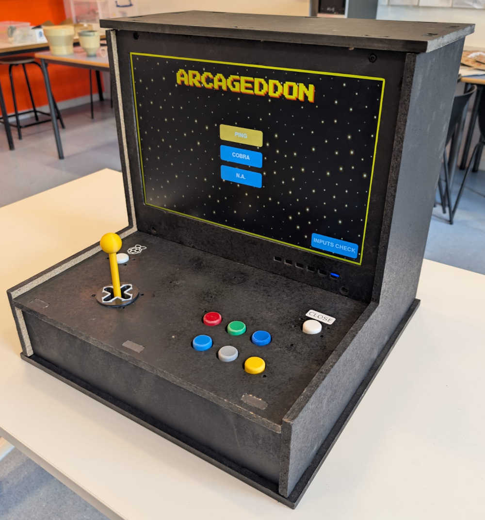
For a few years now, I've always wanted an arcade machine, so for the occasion and with the opportunity of the Fab Academy, I asked myself : "Why not make one ?".
The main idea is to have an arcade machine with lots of games that can be chosen from an interface and play with the different controls on the arcade. I also want to have a plug and play system where games are saved in a storage device and be able to take it off or interact with it to freely add or delete games.
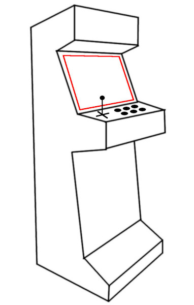
Here's a basic sketch of what I'm aiming for :
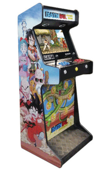
I got the inspiration by looking at different arcade machines that exist and chose the one that I prefer (it comes from the following website : Dragon ball arcade machine).
Here's a list of it's components :
- Body : Made out of wood (MDF or plywood, not too thick or thin)
- Controls : 6 push-buttons to play, 2 push-buttons for menus and a joystick
- video output : Monitor (VGA or HDMI)
- Sound output : Speaker(s)
- Games : Start with simple games made with PyGame, then, if I have the time, download games trough the game engine Godot and load them in a storage device.
- Additional ideas : Lights, stickers, special ports for additional control panel, arm rest, foot rest, ...
Here's a block diagram :
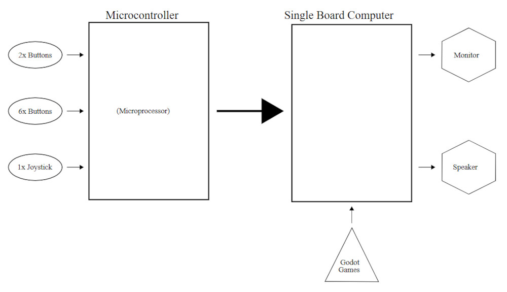
To run games, I'm going to need a SBC (single board computer) because basic microcontrollers aren't powerful enough, for now, I'll use a Raspberry pi 3 (model B) (I eventually switched to a Pi 5).
Making the project
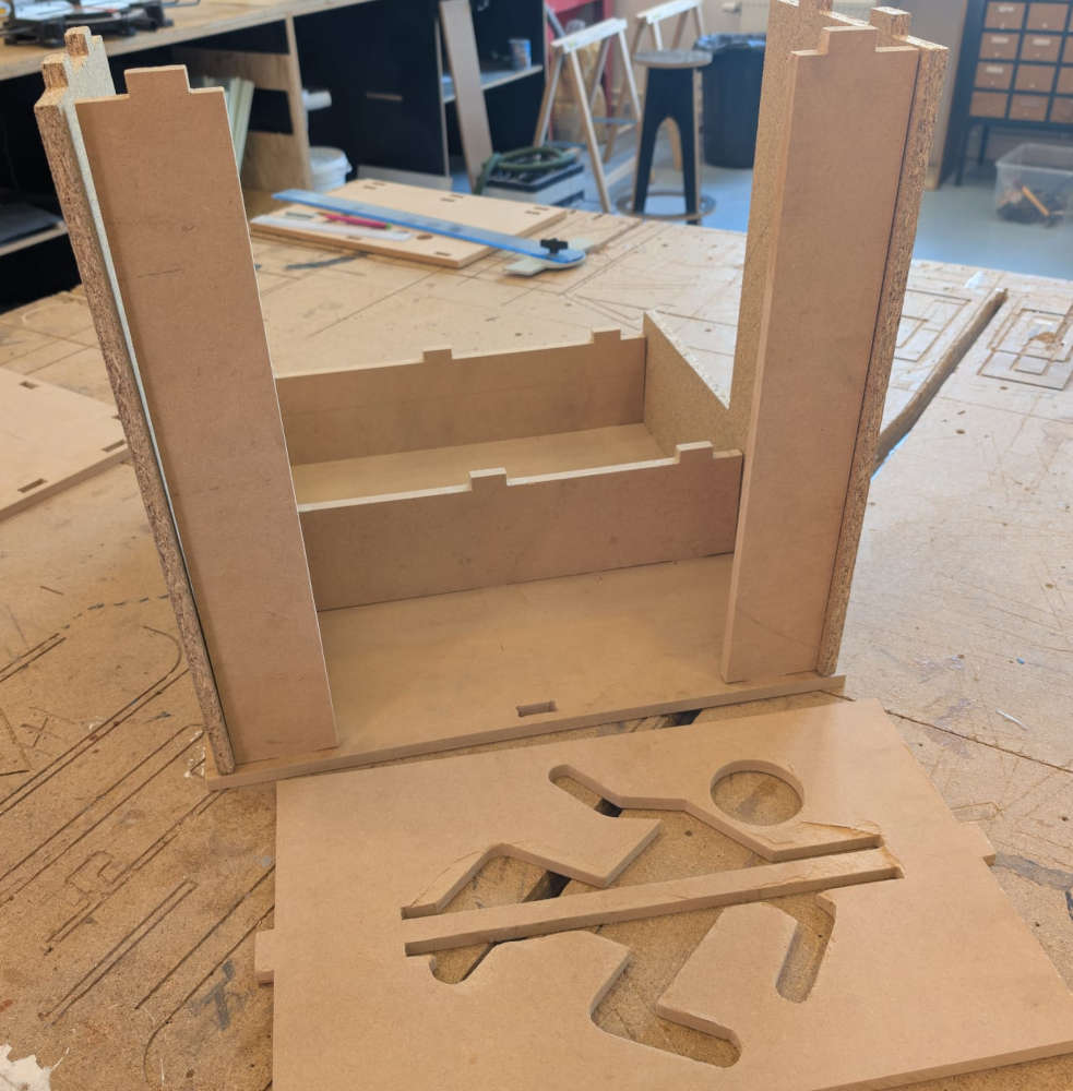
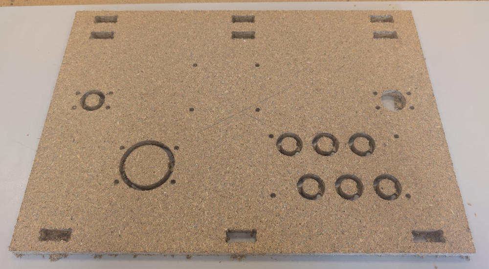
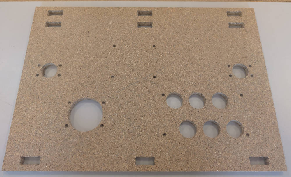
Enclosure
For the enclosure, I'll use the prototype I made on Week 07 (computer-controlled machining) and modify it to integrate everything together.
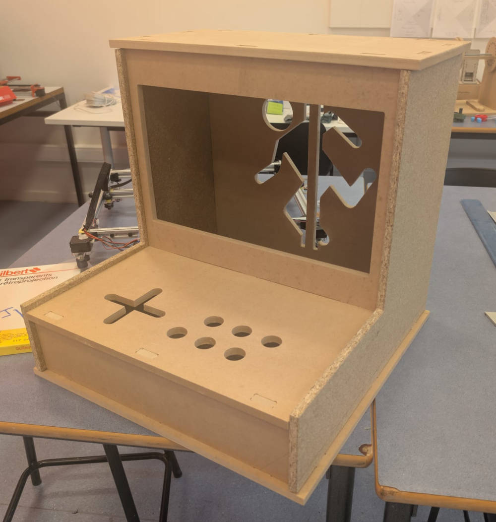
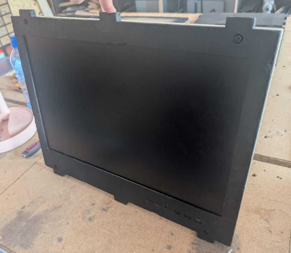
I also painted it black to have a better visual and because 2 types of wood were used which gave it a weird look.
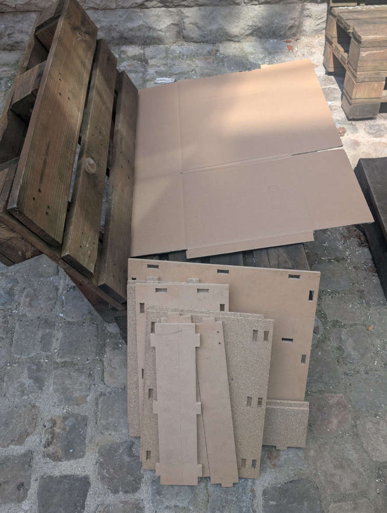
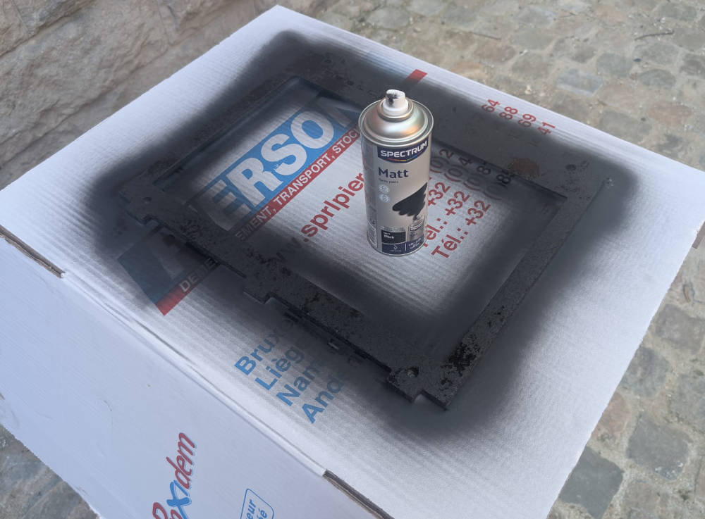
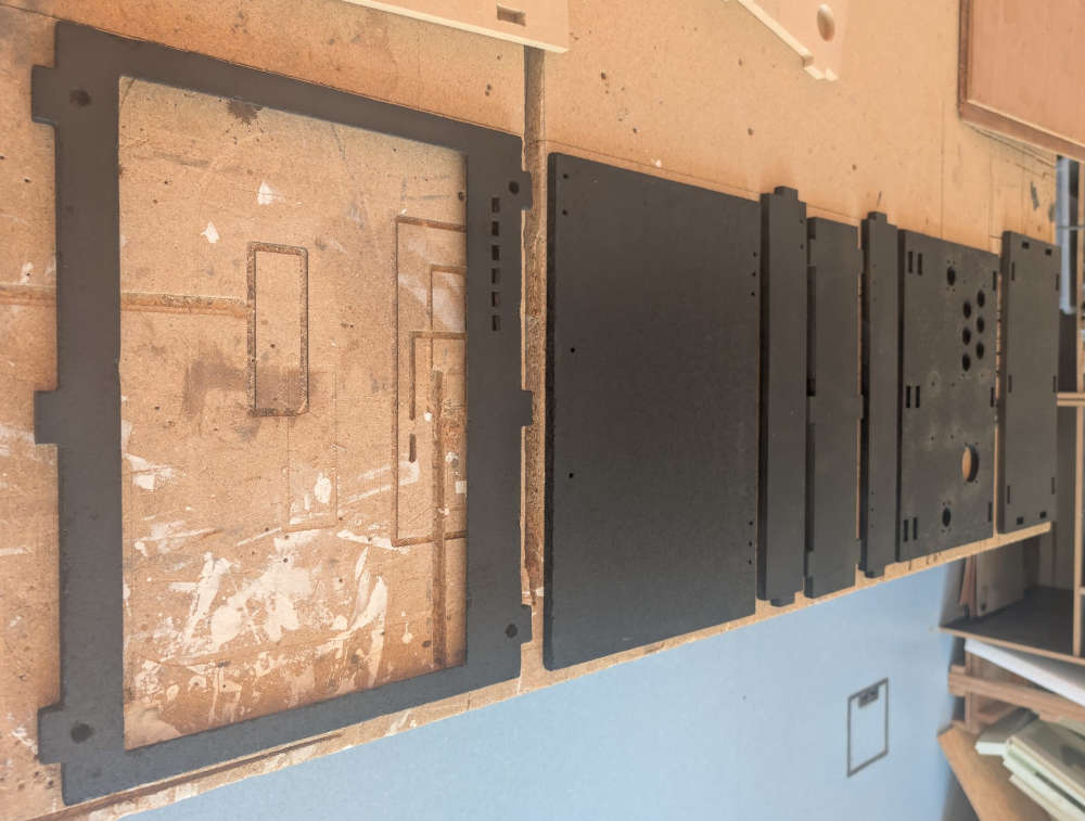
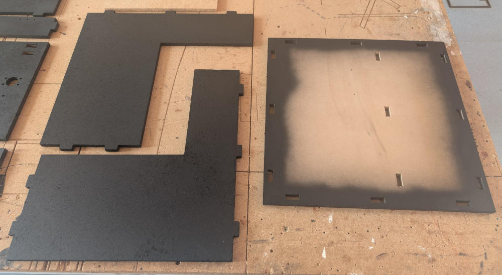
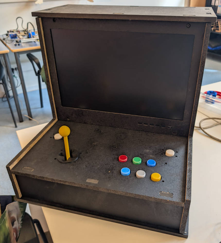
Here's the final result after painting and assembling everything :
Monitor
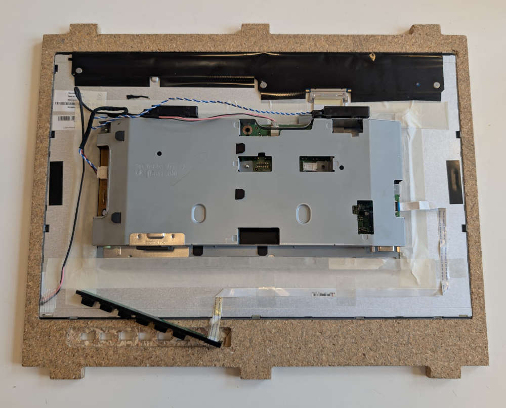
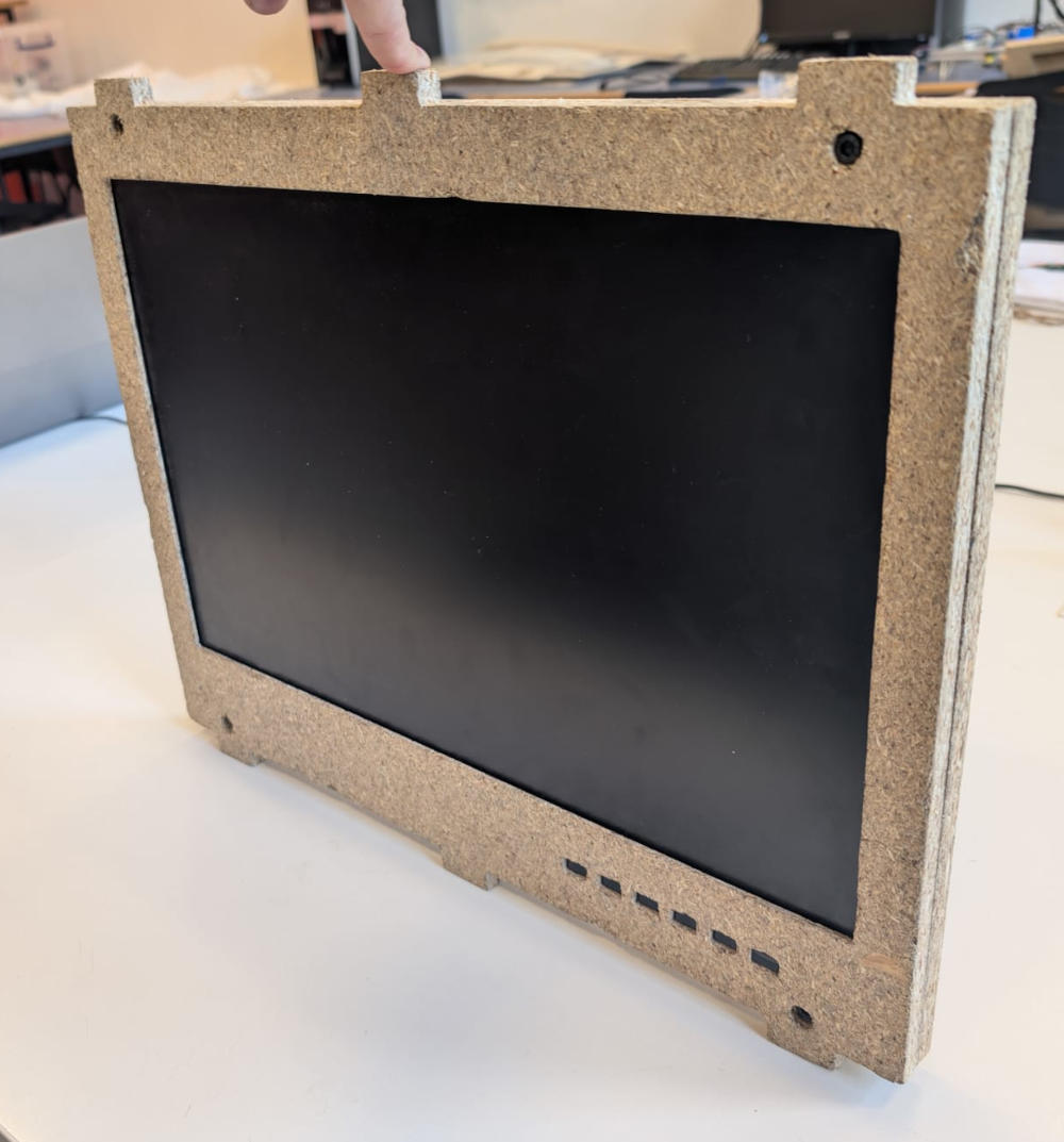
To integrate my monitor to my project, I had to disassemble it to make measurements of the "skeleton" and make a new frame compatible with the enclosure.
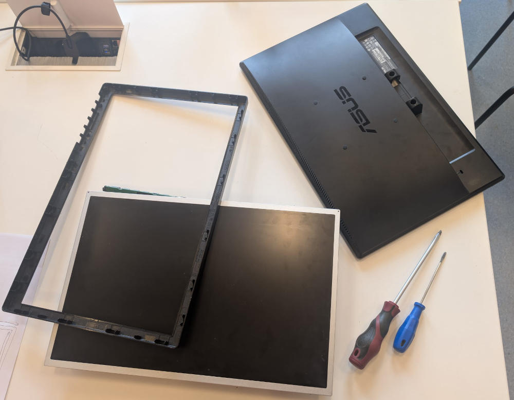

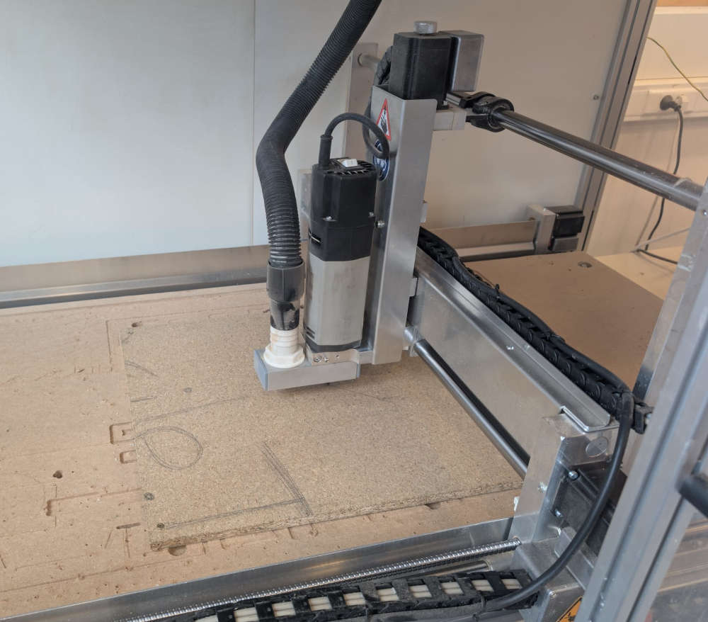
After noting every important measurements, I made two new frames where the idea is to simply sandwich the monitor.
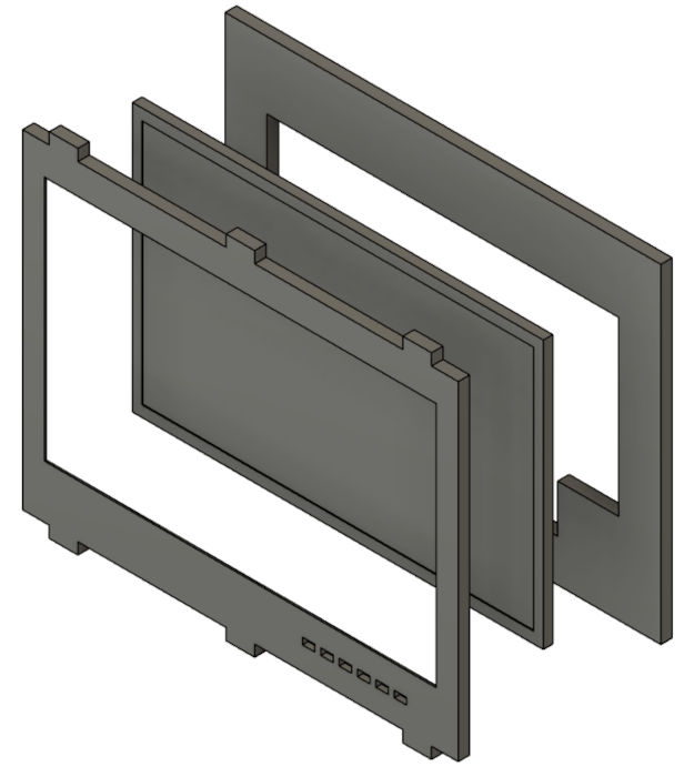
I then use a CNC machine to make the 2 pieces.
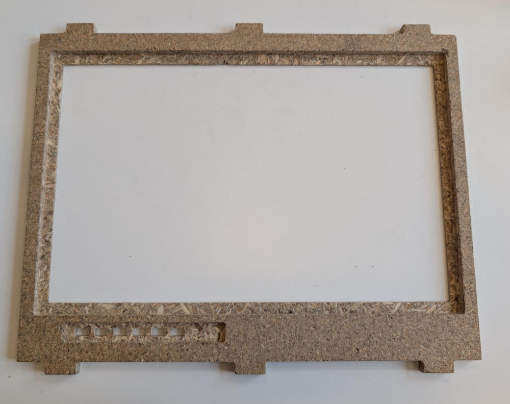
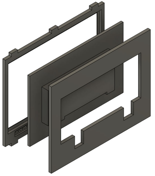
I had to make a second front frame because the first one was a bit too short and the monitor couldn't fit.
I eventually had to use metal files to embiggen the holes of the monitor buttons.
(I also had to add a tiny piece of wood to fix the Buttons PCB because it would move)
I used lock nuts to make sure to tighten the frames together.
Here's the final result :
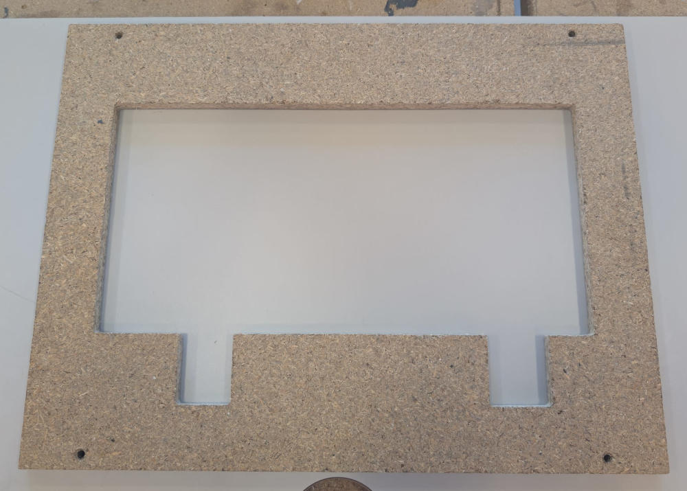
Here's the final result after painting :
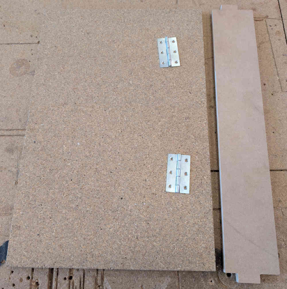
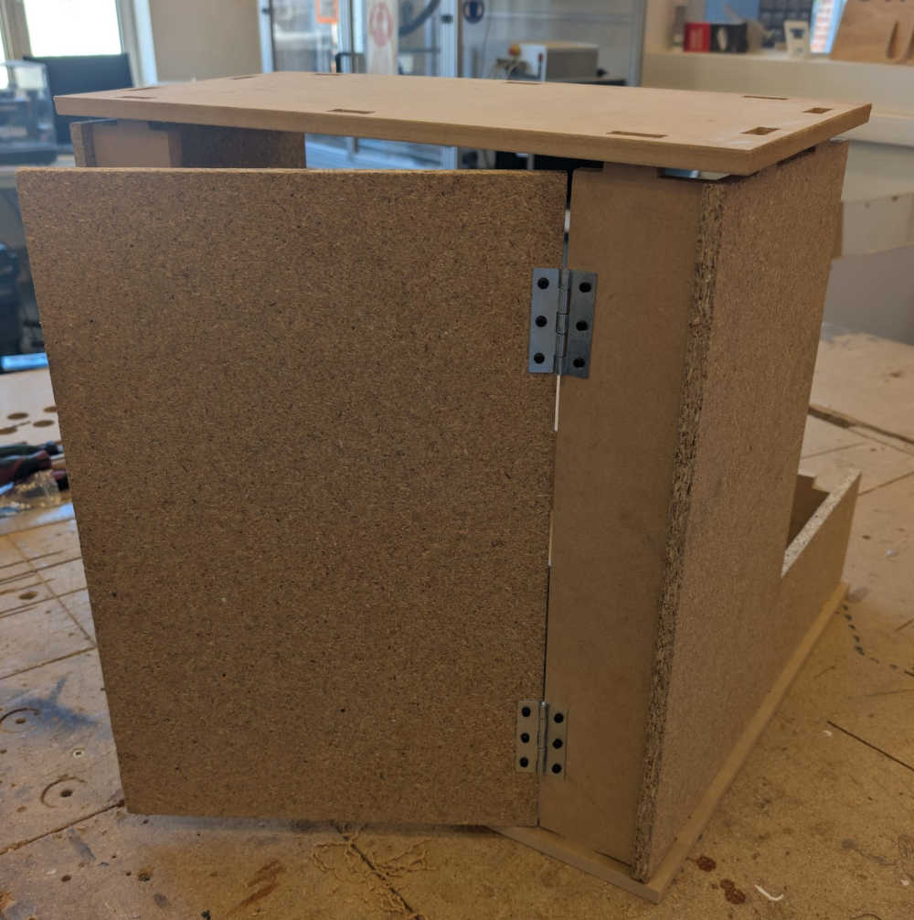
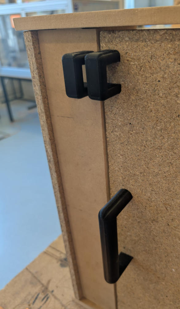
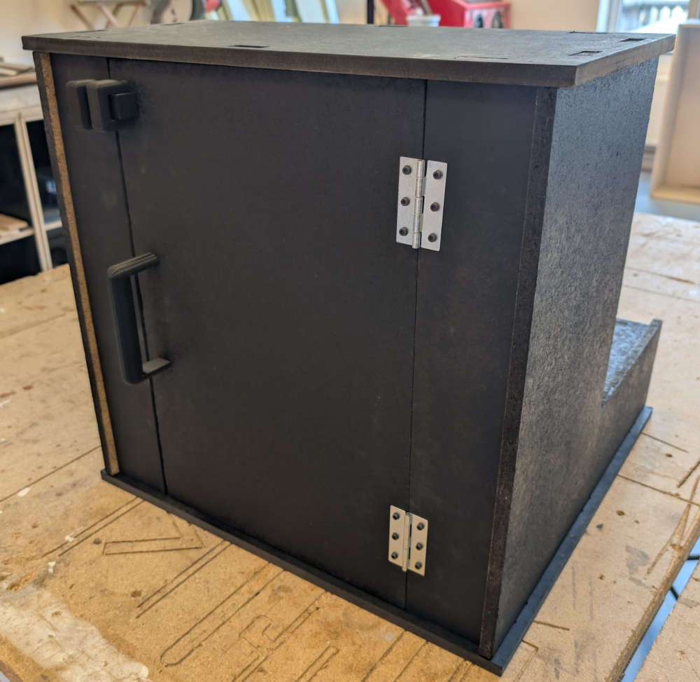
Back door
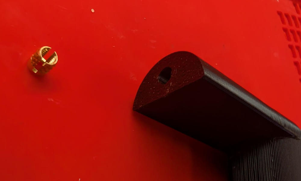
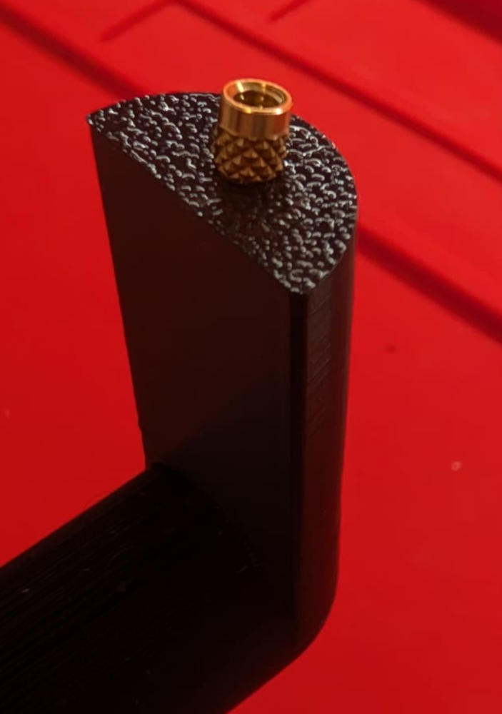
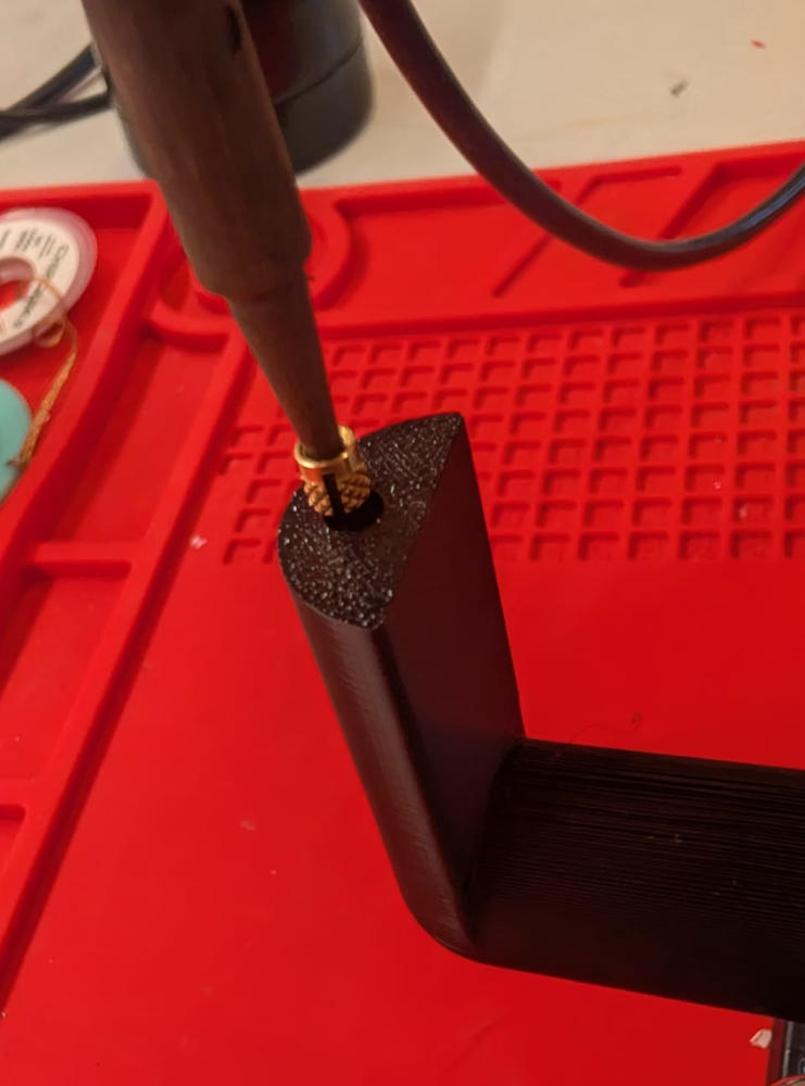
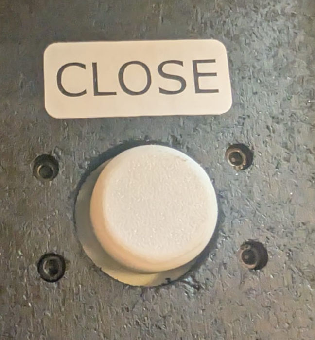
To get access to the inside of the project without having to dismantle everything, I modified the back to have a door and a locking system.
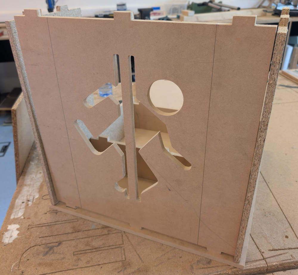
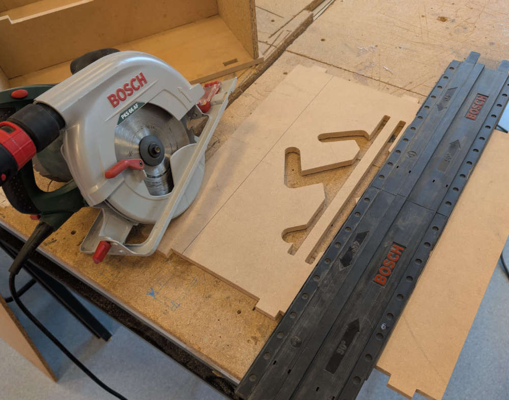
I then use these hinges to make the door.
Then, I add a 3D handle to easily open or close it as well as locking pieces to keep it locked.
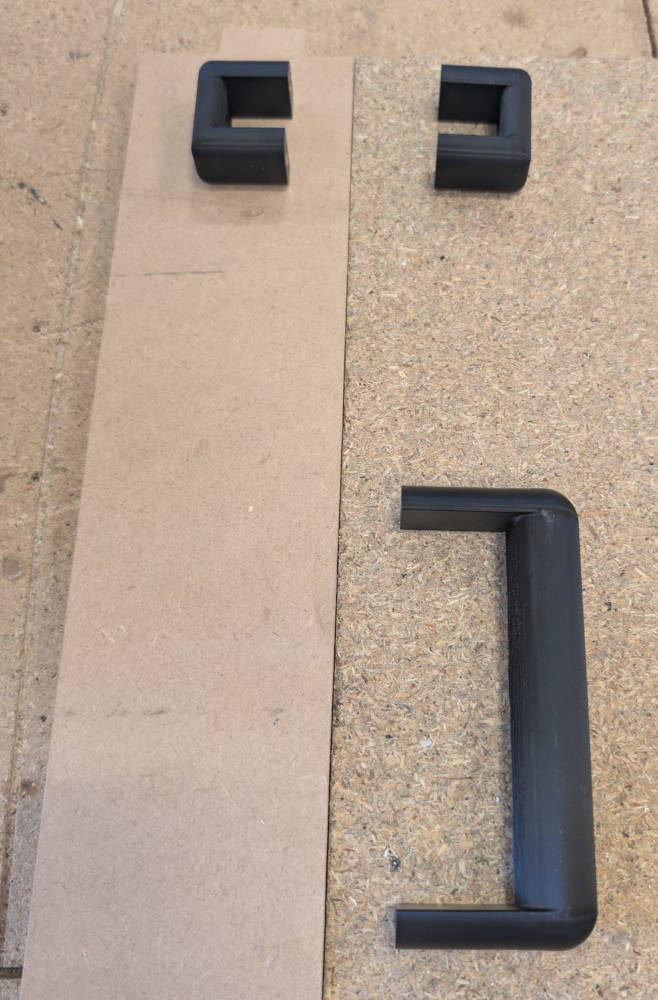
To fix the 3D pieces to the enclosure, I use threaded inserts that i solder into the designated holes.
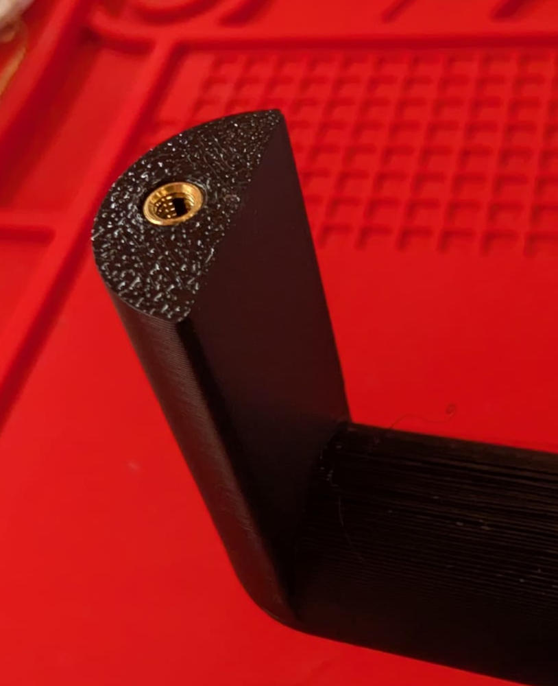
Here's the final result :
Here's the final result after painting and assembling :
PCB modules
Based on the blocks on the block diagram above, I can already make the PCBs of my arcade machine. I'll first do the input modules and then make the microcontroller PCB based on them to be sure the connections with the IDC connectors and ribbon cables are correct.
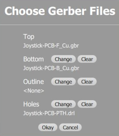
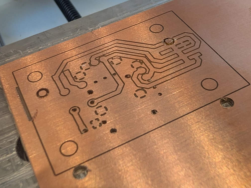
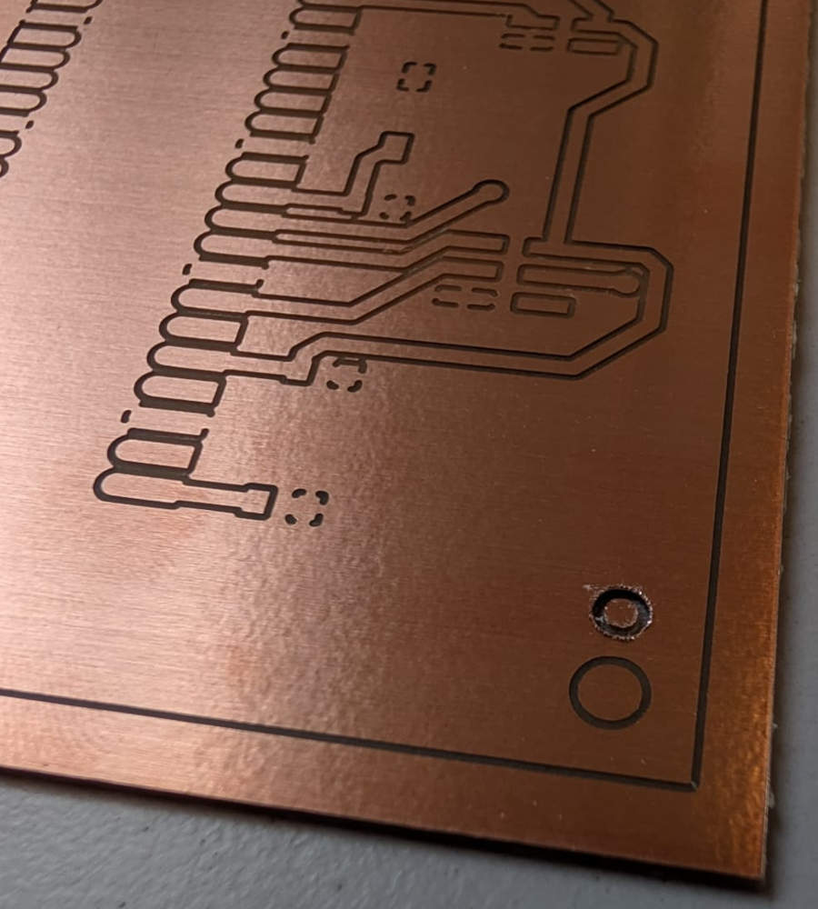
The PCBs were made with the Bantam PCB milling machine with different end mills for tracks and holes/edges.
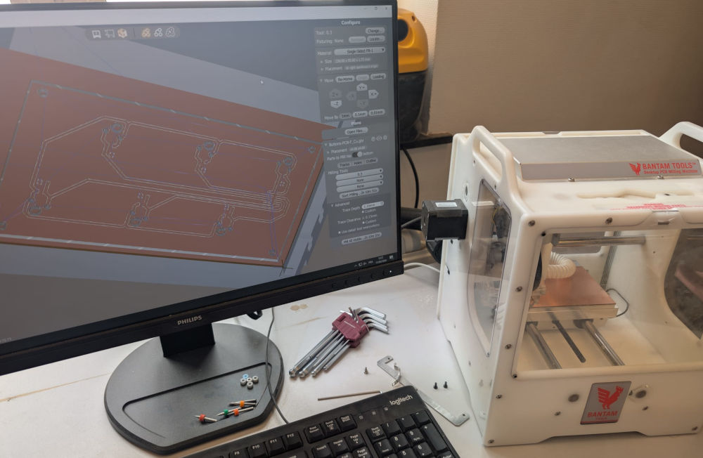
I have to load the correct gerber files or the software will give me weird results : front/top layer, bottom layer and PTH (holes layer) :
-
Joystick
Input module to control the interface and play games.
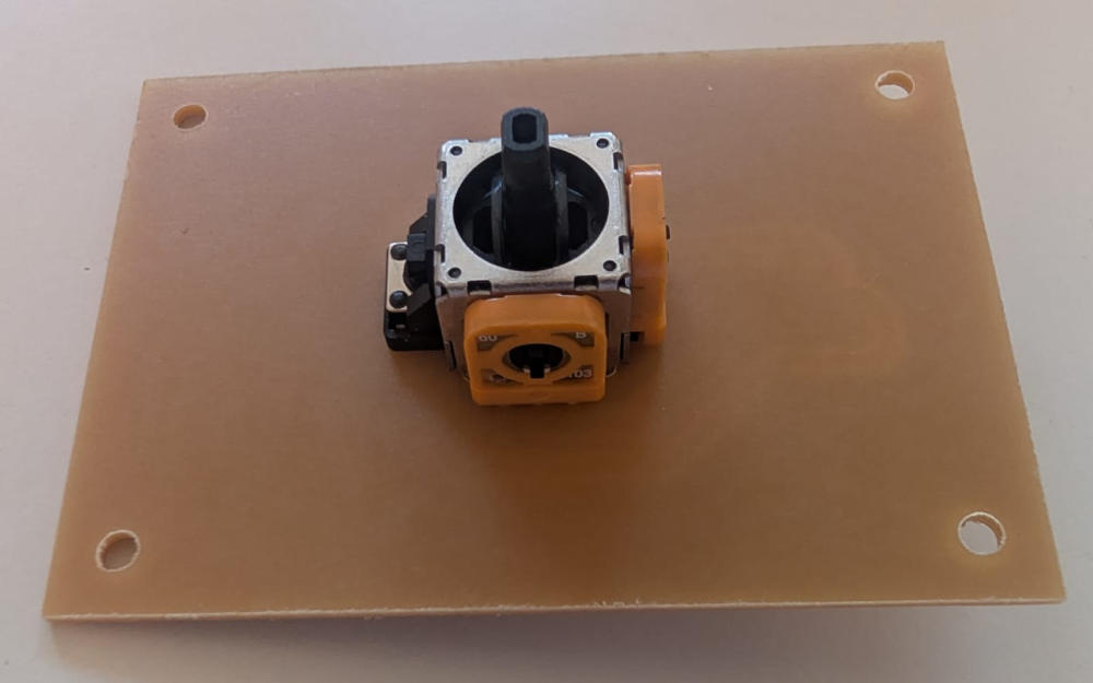
(End mills used : tracks : 0.3mm, holes/edges : 0.6mm)
-
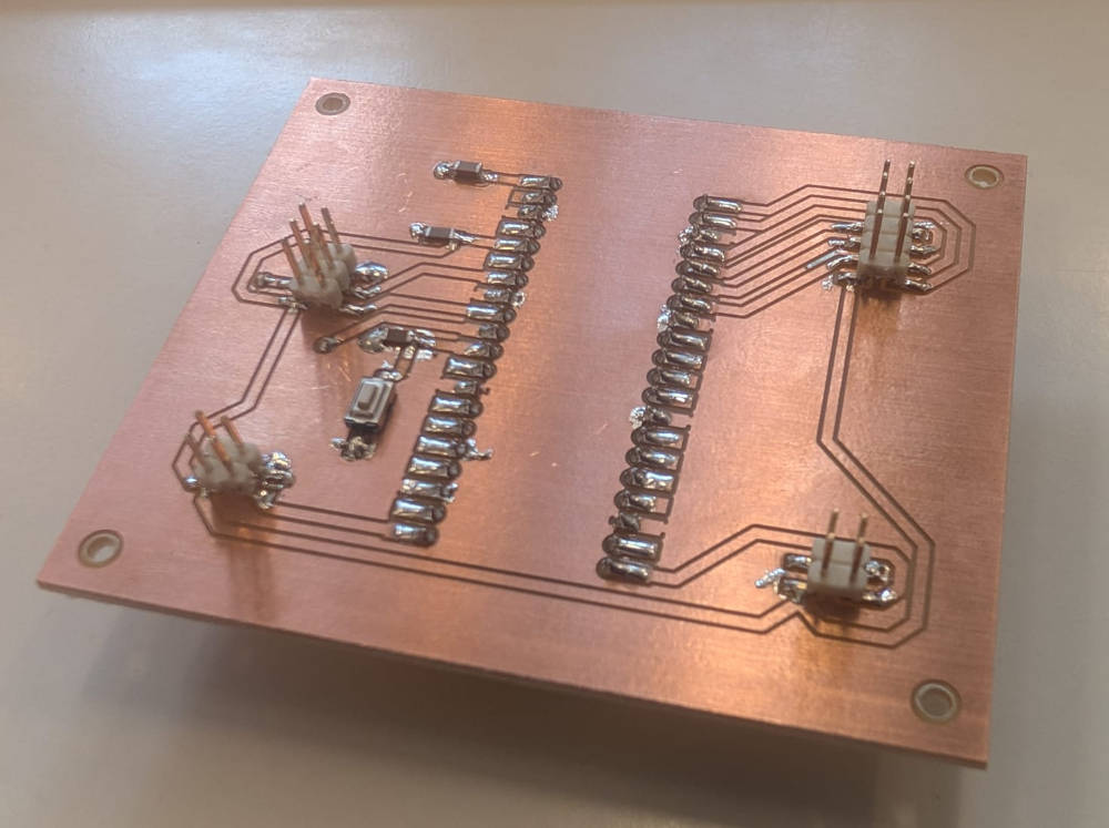
Buttons
Input module to control the interface and play games.
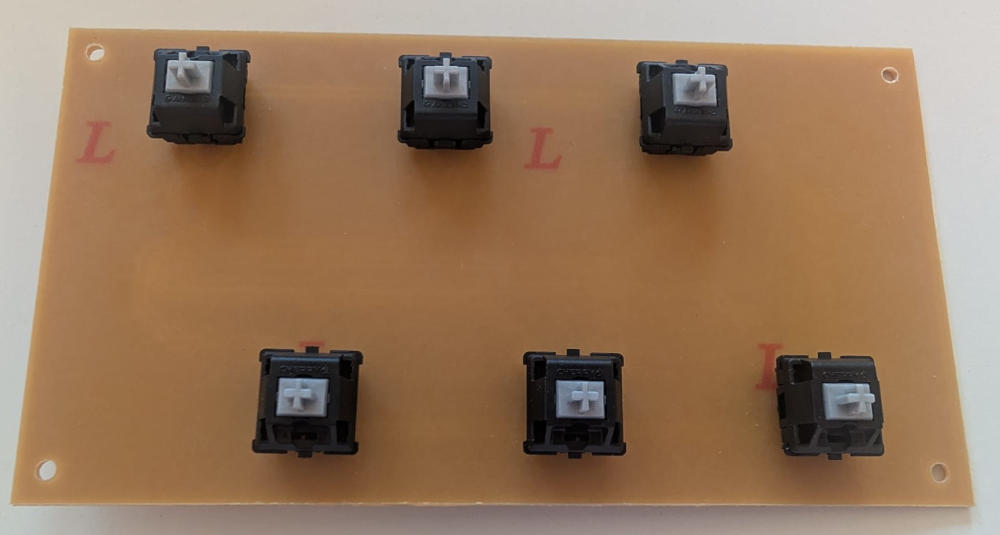
(End mills used : tracks : 0.3mm, holes/edges : 1mm)
-
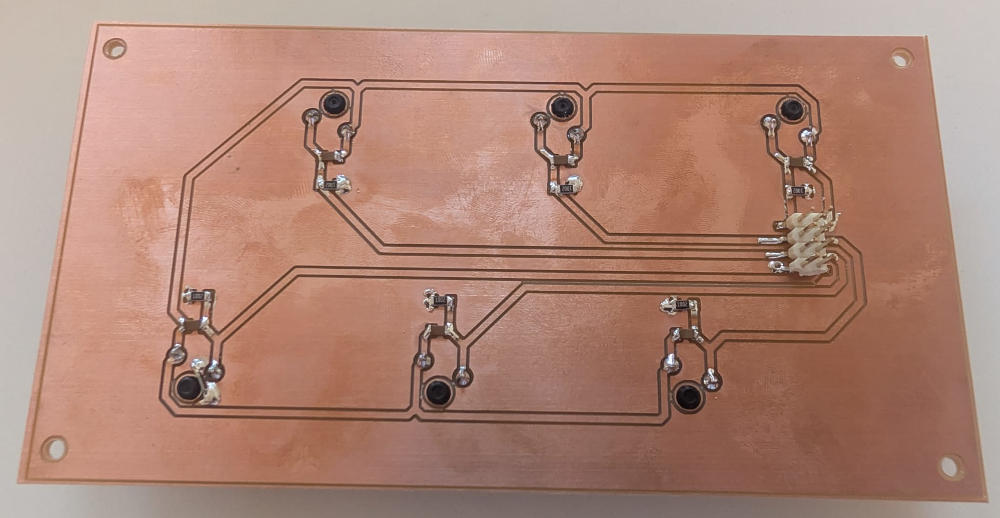
Buttons right and left
Input modules to close the current game and close or launch the interface.
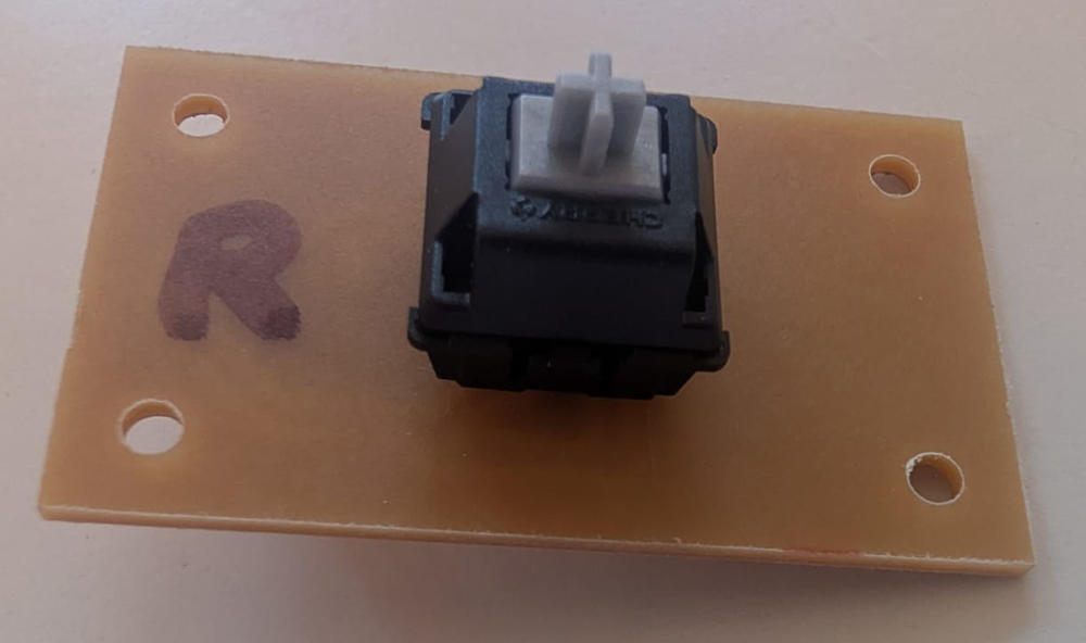
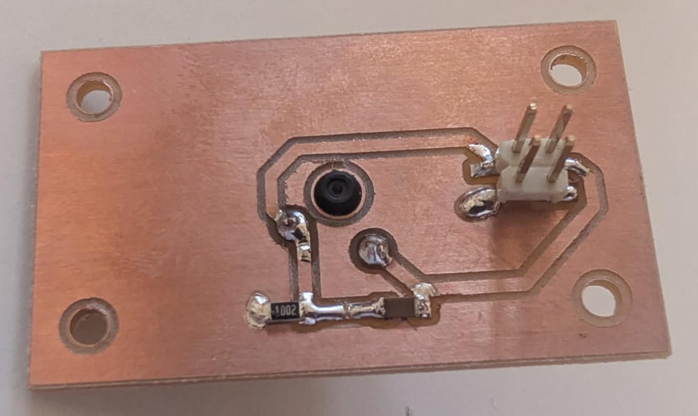
(Button right module)
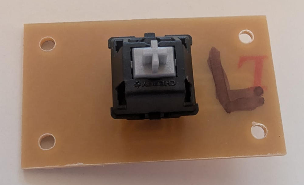
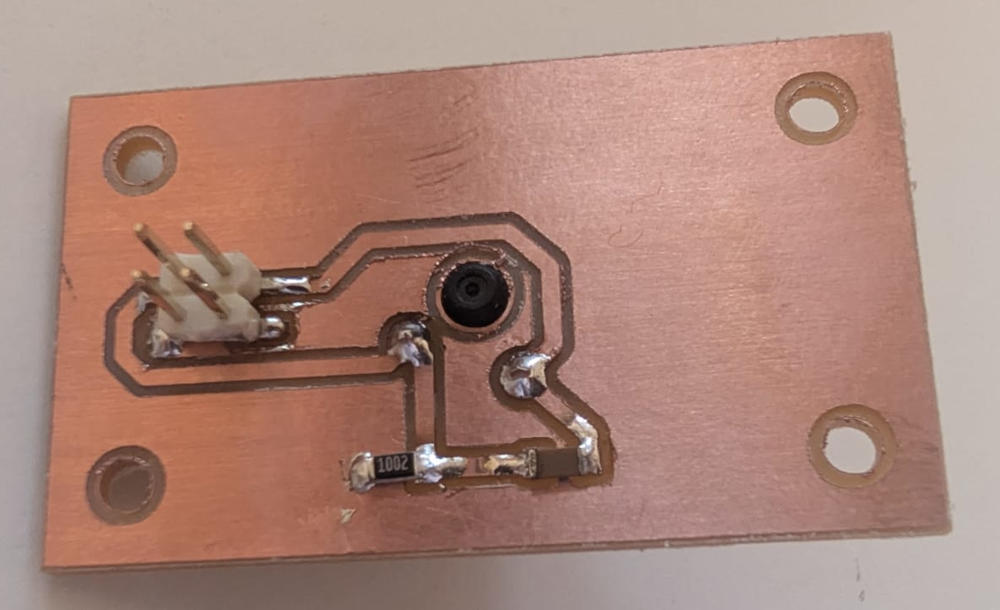
(Button left module)
(End mills used : tracks : 0.3mm, holes/edges : 0.6mm)
-
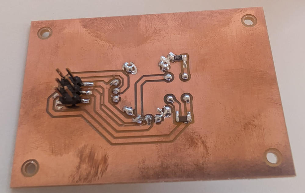
Microcontroller
Main module that receives the data from the input modules and sends it to te Raspberry pi 5.
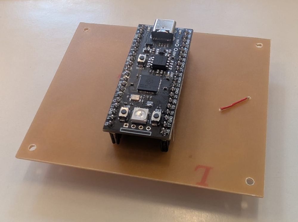
(End mills used : tracks : 0.5mm, holes/edges : 0.9mm)
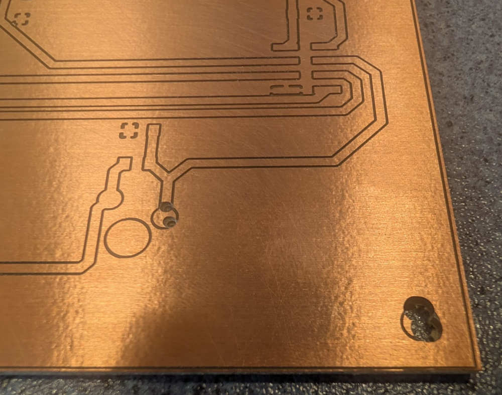
I sometimes wanted to take pictures of the PCB after the tracks or holes/edges operations and this unfortunately messed up the origin of the machine which led me to drilling errors like these :
At some point, I also had to remake the PCB modules to make them bigger to have fixation holes that wont disturb the 3D buttons.
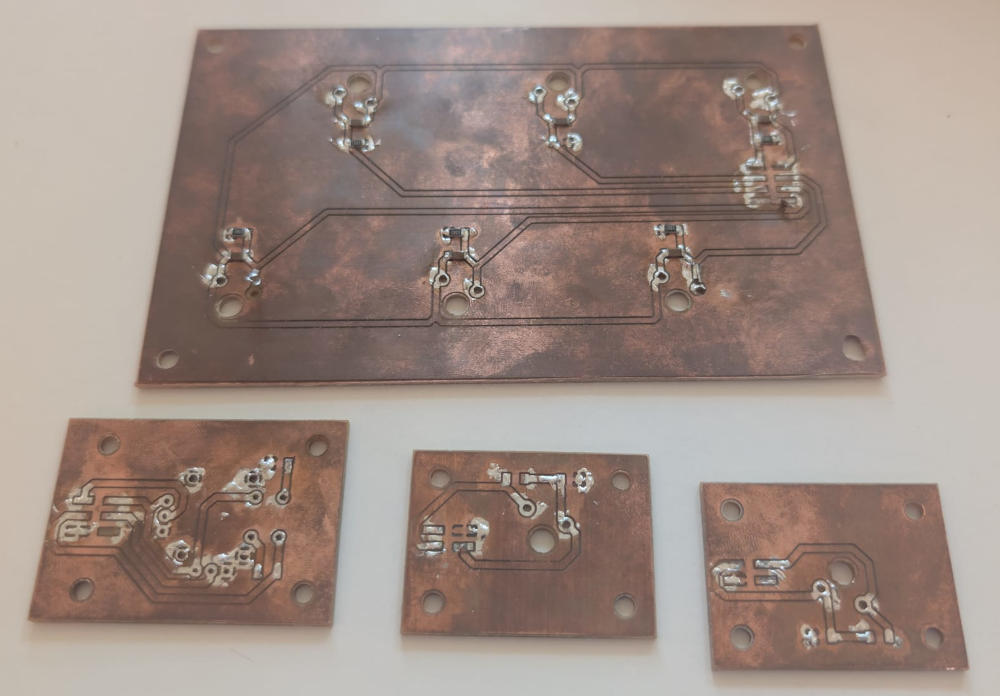
(Old PCB modules)
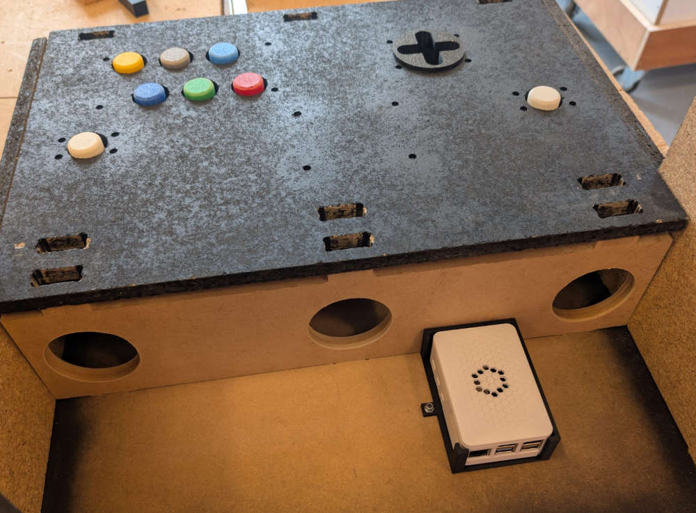
PCB modules integration
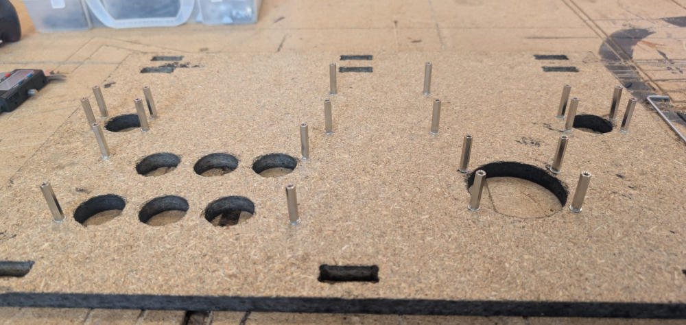
The PCB modules will be fixed on the controller board, which I had to remake to have the good dimensions for the buttons, the joystick hole and the fixation holes.
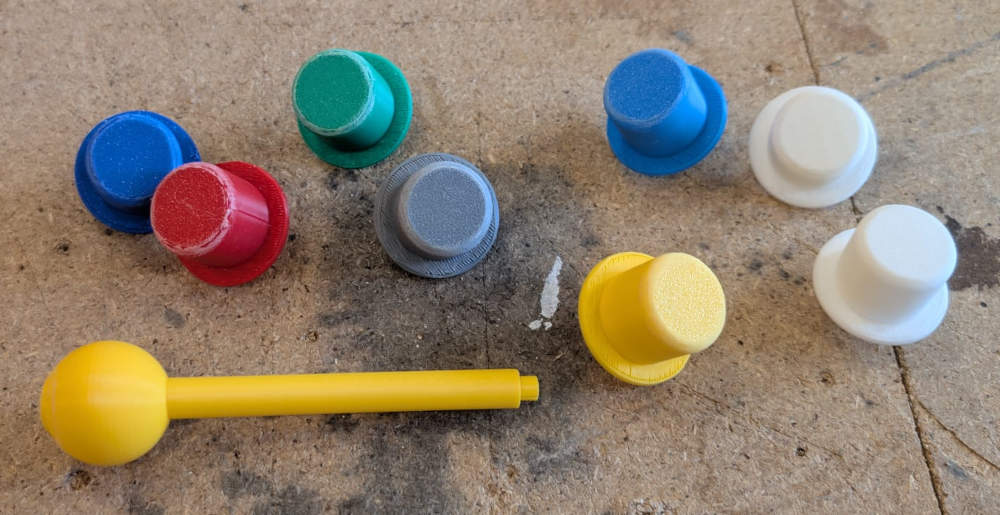
The buttons and the joystick are made in 3D, I first made arrays of holes, each with different dimensions to choose the best one.
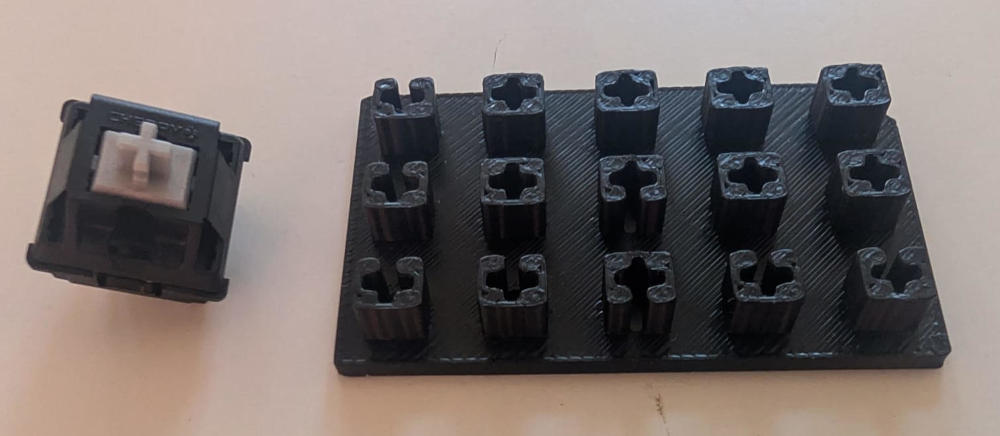
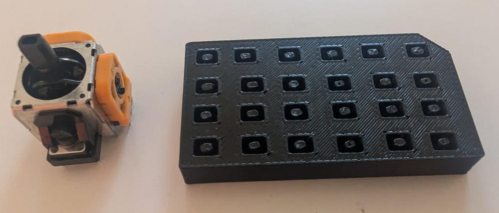
After trying the holes, I choose the best ones, create a first design for both components and print them.
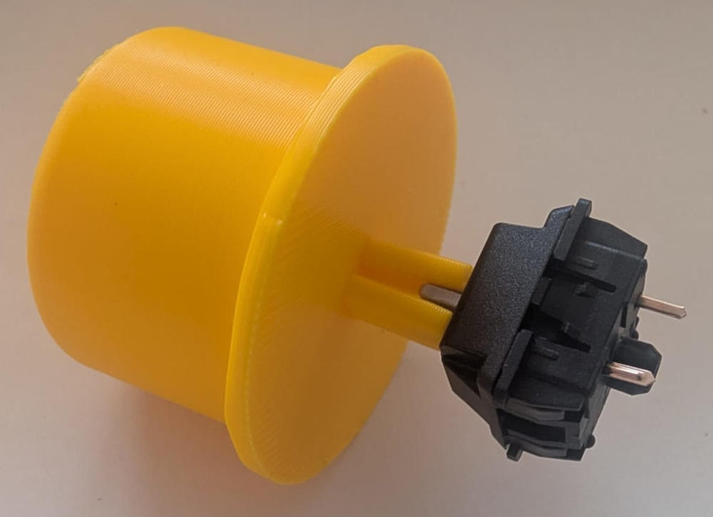
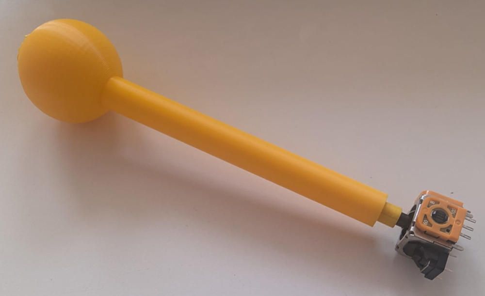
After trying the 3D pieces, I modify them slightly to match the holes (mainly the buttons) and 3D print the final versions.
When everything is ready, I can assemble the PCB modules on the controller board and add the ribbon cables.
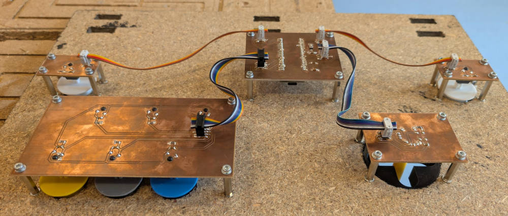
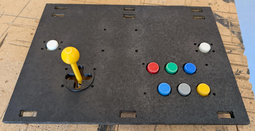
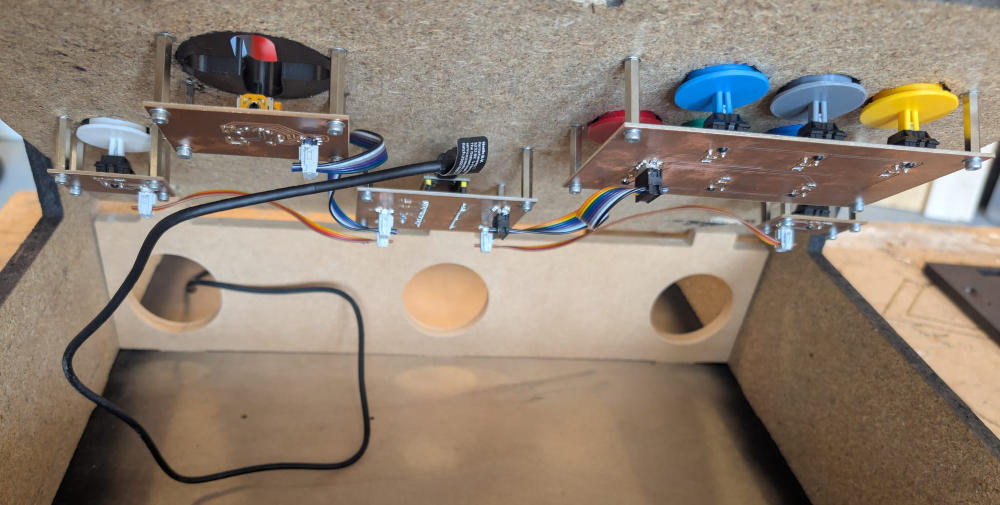
I also added 2 stickers above the white buttons to be easily identified because they are menu buttons.
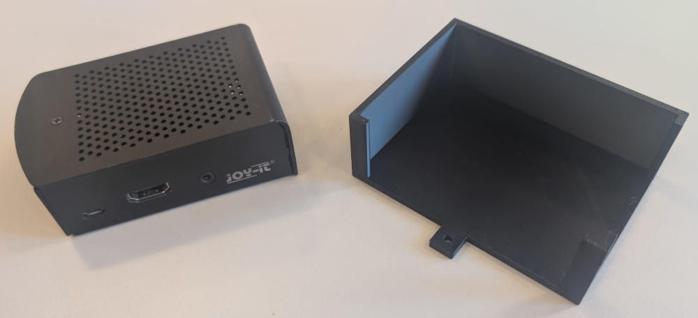
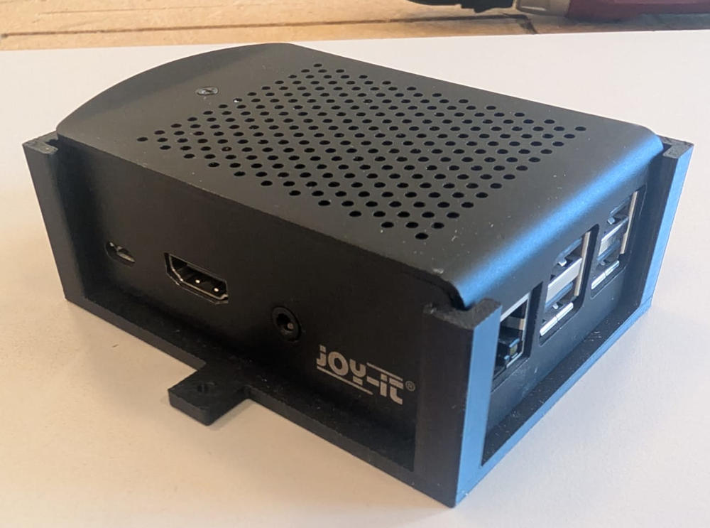
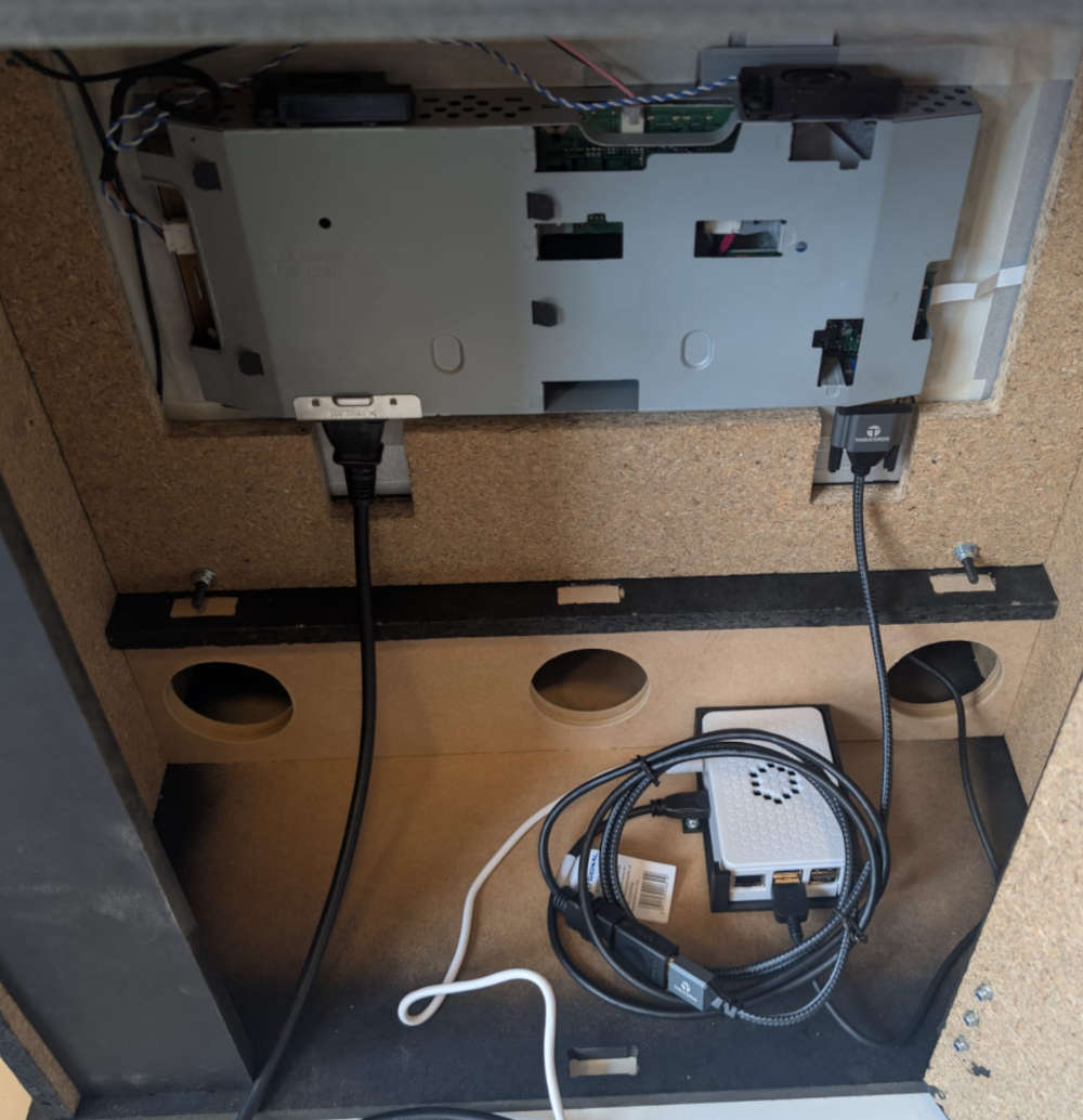
Raspberry Pi 5 integration
The Raspberry Pi 5 will be placed on a 3D holder which is fixed to the enclosure, there is also a hole in one of the wood pieces inside the enclosure that leads to the back door section where the cables for the power supply and monitor cable will pass through.
(At first, I used a Raspberry Pi 3, which is why the case changes color between pictures.)
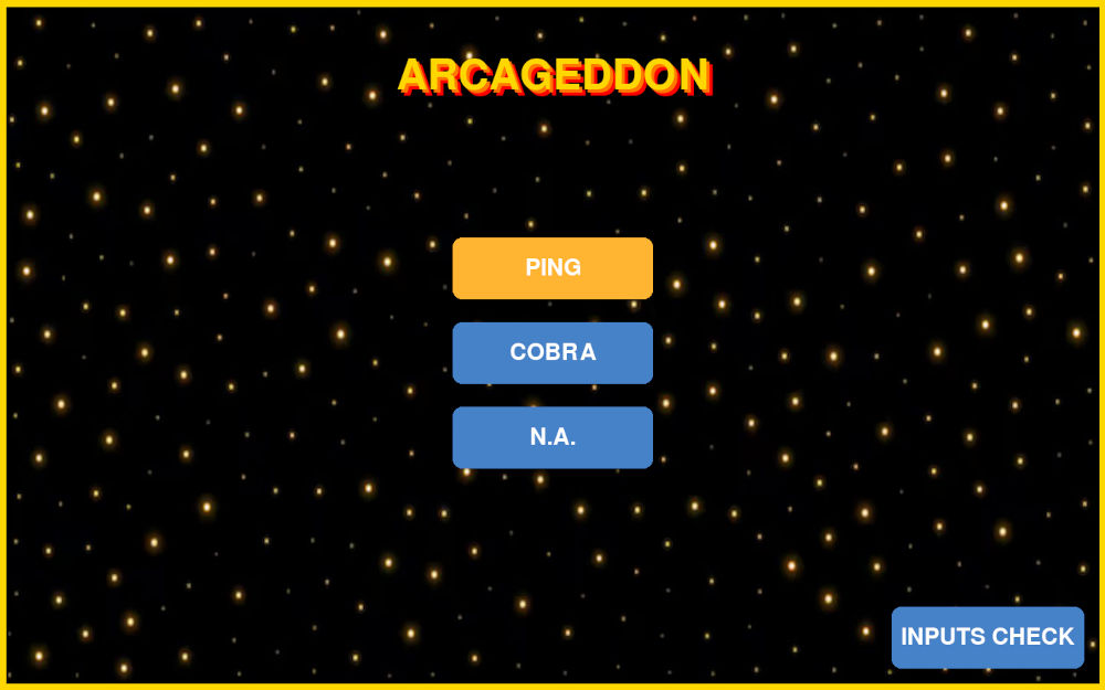
Interface and games
The Raspberry pi 5's purpose is to handle the interface and games.
I plan on making an interface and make simple games using Pygame at first and if I have time, try to implement more complex games.
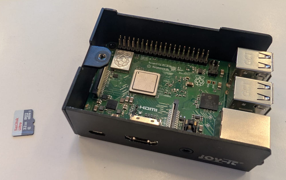
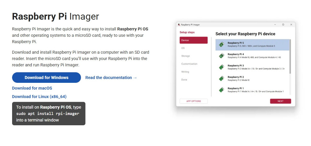
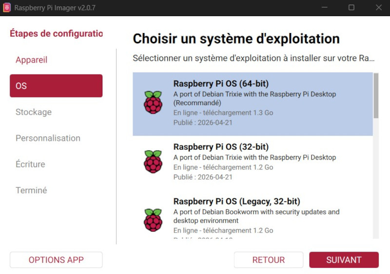
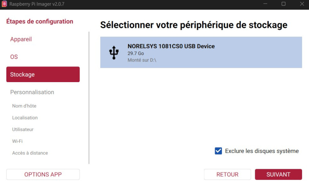
The first thing to do when using a Raspberry Pi is to install its OS, I can do that using the official Raspberry Pi Imager and a 32GB microSD card.
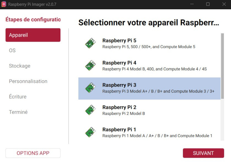
I choose the Raspberry Pi model :
I choose the desired OS :
I choose the microSD card :
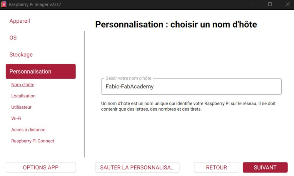
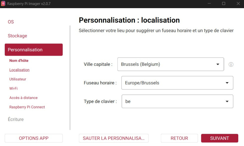
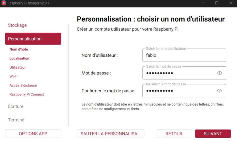
The following parameters to enter some host preferences :
Host name :
Localization :
Username and password :
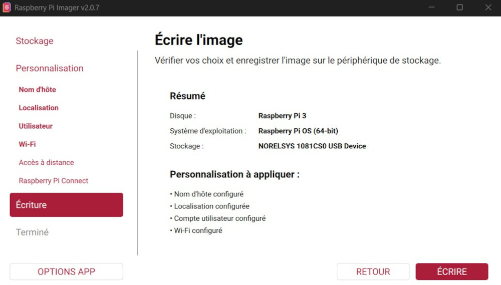
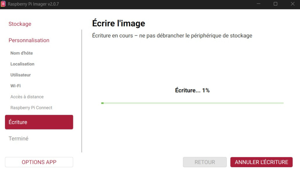
Then I can press the button Ecrire which will install the OS in the microSD card :

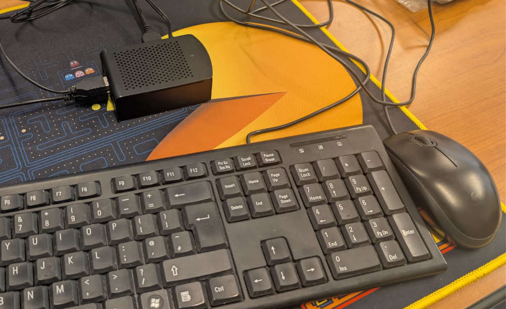
Finally, I can insert the microSD card into the Raspberry pi 5, power it using its power supply and with an additional mouse, keyboard and monitor, interact with it.
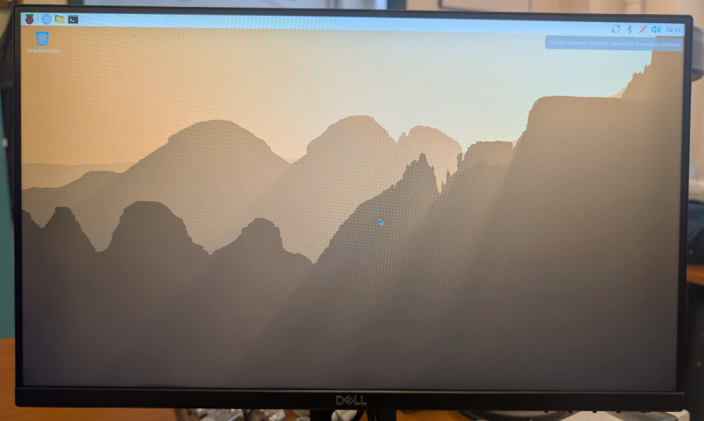
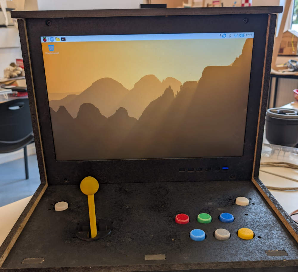
Result on the arcade machine monitor :
Now that everything is ready, I can start coding the USB data reading, handling, the interface and the games using Thonny which is already pre-installed on the Pi.
To start, I need to install pygame and python 3.11 (best for pygame compatibility) on my Raspberry using the terminal and bash commands :
                cd /usr/src
                sudo wget https://www.python.org/ftp/python/3.11.8/Python-3.11.8.tgz
                sudo tar xzf Python-3.11.8.tgz
                cd Python-3.11.8
                sudo ./configure --enable-optimizations
                sudo make -j4
                sudo make altinstall
                python3.11 -m pip install pygame
Then, I heavily rely on ChatGPT to make the interface and games exactly how I want them to look and work like.
-
Controller
Code of the Raspberry Pi Pico, sends data based on the buttons pressed or the joystick's position.
from machine import Pin, ADC import time # Joystick Joystick_Axis_X = ADC(Pin(26)) Joystick_Axis_Y = ADC(Pin(27)) Joystick_Push_button = Pin(28, Pin.IN) # Button right Button_Right = Pin(15, Pin.IN) # Button left Button_Left = Pin(16, Pin.IN) # Buttons Buttons_A = Pin(0, Pin.IN) Buttons_B = Pin(1, Pin.IN) Buttons_C = Pin(2, Pin.IN) Buttons_D = Pin(5, Pin.IN) Buttons_E = Pin(4, Pin.IN) Buttons_F = Pin(3, Pin.IN) while True: # Joystick reading Joystick_Axis_X_Value = Joystick_Axis_X.read_u16() Joystick_Axis_Y_Value = Joystick_Axis_Y.read_u16() Joystick_Push_button_Value = Joystick_Push_button.value() # Button right reading Button_Right_Value = Button_Right.value() # Button left reading Button_Left_Value = Button_Left.value() # Buttons reading Buttons_A_Value = Buttons_A.value() Buttons_B_Value = Buttons_B.value() Buttons_C_Value = Buttons_C.value() Buttons_D_Value = Buttons_D.value() Buttons_E_Value = Buttons_E.value() Buttons_F_Value = Buttons_F.value() # Joystick data transmission if Joystick_Axis_X_Value < 20000: print("LEFT") if Joystick_Axis_X_Value > 40000: print("RIGHT") if Joystick_Axis_Y_Value < 20000: print("DOWN") if Joystick_Axis_Y_Value > 40000: print("UP") if (Joystick_Axis_X_Value > 20000) and (Joystick_Axis_X_Value < 40000) and (Joystick_Axis_Y_Value > 20000) and (Joystick_Axis_Y_Value < 40000): print("STOP") if Joystick_Push_button_Value == 1: print("PB") # Button right data transmission if Button_Right_Value == 1: print("CLOSE") # Button left data transmission if Button_Left_Value == 1: print("RASP") # Buttons data transmission if Buttons_A_Value == 1: print("A") if Buttons_B_Value == 1: print("B") if Buttons_C_Value == 1: print("C") if Buttons_D_Value == 1: print("D") if Buttons_E_Value == 1: print("E") if Buttons_F_Value == 1: print("F") # Delay time.sleep(0.2) -
Interface
Initial screen of the arcade machine, let's me choose the games to play.
import pygame import sys from usb_reader import USBReader import subprocess # ---------------------------- # USB START # ---------------------------- usb = USBReader() # ---------------------------- # PYGAME SETUP # ---------------------------- pygame.init() pygame.mouse.set_visible(False) WIDTH, HEIGHT = 1440, 900 screen = pygame.display.set_mode((WIDTH, HEIGHT)) pygame.display.set_caption("ARCAGEDDON UI") bg_image = pygame.image.load("background.jpg").convert() bg_image = pygame.transform.scale(bg_image, (WIDTH, HEIGHT)) clock = pygame.time.Clock() # ---------------------------- # COLORS # ---------------------------- BG = (18, 18, 18) BTN = (70, 130, 200) BTN_SELECTED = (255, 180, 50) WHITE = (255, 255, 255) YELLOW = (255, 215, 0) # ---------------------------- # FONTS # ---------------------------- font = pygame.font.SysFont(None, 45) title_font = pygame.font.SysFont("Press Start 2P", 80) # ---------------------------- # BUTTON CLASS # ---------------------------- class Button: def __init__(self, x, y, w, h, text): self.rect = pygame.Rect(x, y, w, h) self.text = text def draw(self, surface, selected=False): color = BTN_SELECTED if selected else BTN pygame.draw.rect(surface, color, self.rect, border_radius=12) label = font.render(self.text, True, WHITE) surface.blit(label, label.get_rect(center=self.rect.center)) # ---------------------------- # LAYOUT # ---------------------------- menu_btn_w, menu_btn_h = 250, 80 btn_w, btn_h = 260, 80 spacing = 30 center_x = WIDTH // 2 - btn_w // 2 start_y = HEIGHT // 2 - 140 center_buttons = [ Button(center_x, start_y, btn_w, btn_h, "PING"), Button(center_x, start_y + btn_h + spacing, btn_w, btn_h, "COBRA"), Button(center_x, start_y + 2 * (btn_h + spacing), btn_w, btn_h, "N.A."), ] menu_button = Button( WIDTH - menu_btn_w - 30, HEIGHT - menu_btn_h - 30, menu_btn_w, menu_btn_h, "INPUTS CHECK" ) # ---------------------------- # STATE # ---------------------------- selected_index = 0 saved_index = 0 focus_mode = "CENTER" game_process = None input_process = None # ---------------------------- # MAIN LOOP # ---------------------------- running = True while running: screen.blit(bg_image, (0, 0)) pygame.draw.rect( screen, YELLOW, screen.get_rect(), width=10 ) # ---------------------------- # CHECK GAME STATUS # ---------------------------- if game_process is not None and game_process.poll() is not None: game_process = None # ---------------------------- # USB INPUT (SAFE POLLING) # ---------------------------- cmd = usb.read() # EMERGENCY EXIT COMMAND if cmd == "RASP": running = False if cmd: if focus_mode == "CENTER": if cmd == "UP": selected_index = (selected_index - 1) % len(center_buttons) elif cmd == "DOWN": selected_index = (selected_index + 1) % len(center_buttons) elif cmd == "RIGHT": saved_index = selected_index focus_mode = "MENU" elif cmd == "A": if game_process is None: selected_game = center_buttons[selected_index].text if selected_game == "PING": game_process = subprocess.Popen( [sys.executable, "game_1.py"], stdin=subprocess.PIPE, text=True ) elif selected_game == "COBRA": game_process = subprocess.Popen( [sys.executable, "game_2.py"], stdin=subprocess.PIPE, text=True ) elif selected_game == "N.A.": game_process = subprocess.Popen( [sys.executable, "game_3.py"], stdin=subprocess.PIPE, text=True ) elif focus_mode == "MENU": if cmd == "LEFT": focus_mode = "CENTER" selected_index = saved_index elif cmd == "A": if input_process is None or input_process.poll() is not None: input_process = subprocess.Popen( [sys.executable, "input.py"], stdin=subprocess.PIPE, text=True ) # ---------------------------- # SEND INPUT TO INPUTS CHECK # ---------------------------- if input_process is not None and input_process.poll() is None: try: input_process.stdin.write(cmd + "\n") input_process.stdin.flush() except: pass # ---------------------------- # SEND INPUT TO GAME # ---------------------------- if game_process is not None and game_process.poll() is None: try: if cmd: game_process.stdin.write(cmd + "\n") game_process.stdin.flush() except: pass # ---------------------------- # EVENTS # ---------------------------- for event in pygame.event.get(): if event.type == pygame.QUIT: running = False if event.type == pygame.KEYDOWN and event.key == pygame.K_ESCAPE: running = False # ---------------------------- # TITLE (RESTORED SHADOW EFFECT) # ---------------------------- # bottom layer (furthest shadow) - RED shadow_red = title_font.render("ARCAGEDDON", True, (255, 0, 0)) shadow_red_rect = shadow_red.get_rect(center=(WIDTH // 2 + 8, 108)) screen.blit(shadow_red, shadow_red_rect) # middle layer - ORANGE shadow_orange = title_font.render("ARCAGEDDON", True, (255, 120, 0)) shadow_orange_rect = shadow_orange.get_rect(center=(WIDTH // 2 + 4, 104)) screen.blit(shadow_orange, shadow_orange_rect) # top layer (main text) - YELLOW main_text = title_font.render("ARCAGEDDON", True, YELLOW) main_rect = main_text.get_rect(center=(WIDTH // 2, 100)) screen.blit(main_text, main_rect) # ---------------------------- # DRAW UI # ---------------------------- menu_button.draw(screen, selected=(focus_mode == "MENU")) for i, b in enumerate(center_buttons): b.draw(screen, selected=(focus_mode == "CENTER" and i == selected_index)) pygame.display.flip() clock.tick(60) # ---------------------------- # EXIT # ---------------------------- usb.stop() pygame.quit() sys.exit() -
USB data
Program that reads the USB communication.
import serial import time class USBReader: def __init__(self): self.PORT = "/dev/serial/by-id/usb-MicroPython_Board_in_FS_mode_de6258c0c3143639-if00" self.BAUD = 115200 print("Connecting to device...") self.ser = serial.Serial(self.PORT, self.BAUD, timeout=1) time.sleep(2) print("Connected!") self.latest = None def start(self): # intentionally empty (kept for compatibility) pass def read(self): try: line = self.ser.readline() if not line: return self.latest line = line.decode("utf-8", errors="ignore").strip() if line: self.latest = line.upper() except Exception as e: print("USB ERROR:", e) return self.latest def stop(self): try: self.ser.close() except: pass -
Game 1 (Pong)
Game 1 of the arcade machine, copy of the popular game "Pong" with a customized screen.
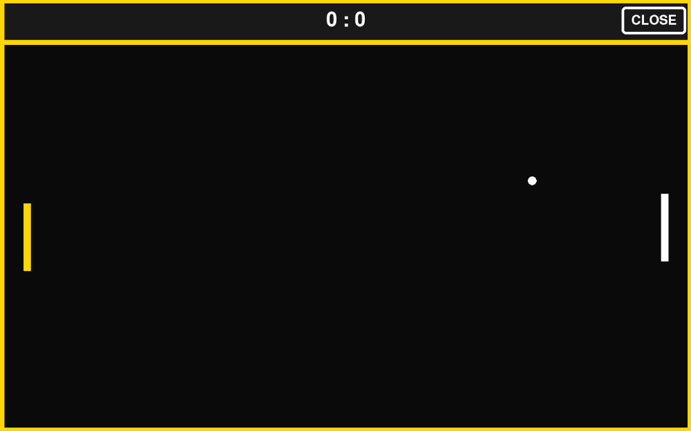
import pygame import sys import os import select def get_cmd(): if select.select([sys.stdin], [], [], 0)[0]: return sys.stdin.readline().strip().upper() return None def close_game(): pygame.quit() os._exit(0) pygame.init() pygame.mouse.set_visible(False) WIDTH, HEIGHT = 1440, 900 screen = pygame.display.set_mode((WIDTH, HEIGHT)) pygame.display.set_caption("Pong Arcade") clock = pygame.time.Clock() FPS = 60 BLACK = (10, 10, 10) WHITE = (255, 255, 255) YELLOW = (255, 215, 0) DARK = (25, 25, 25) HUD_HEIGHT = int(HEIGHT * 0.10) GAME_HEIGHT = HEIGHT - HUD_HEIGHT player_score = 0 ai_score = 0 font = pygame.font.SysFont(None, 60) small_font = pygame.font.SysFont(None, 40) big_font = pygame.font.SysFont(None, 90) PADDLE_W, PADDLE_H = 15, 140 BALL_SIZE = 18 PADDLE_SPEED = 8 left_paddle = pygame.Rect( 50, HUD_HEIGHT + GAME_HEIGHT // 2 - PADDLE_H // 2, PADDLE_W, PADDLE_H ) right_paddle = pygame.Rect( WIDTH - 50 - PADDLE_W, HUD_HEIGHT + GAME_HEIGHT // 2 - PADDLE_H // 2, PADDLE_W, PADDLE_H ) ball = pygame.Rect( WIDTH // 2, HUD_HEIGHT + GAME_HEIGHT // 2, BALL_SIZE, BALL_SIZE ) ball_vel_x = 6 ball_vel_y = 6 move_up = False move_down = False # ---------------------------- # WIN SYSTEM (FIXED) # ---------------------------- game_over = False winner_text = None win_timer = None WIN_WAIT = 3000 # 3 seconds def reset_ball(direction=1): global ball_vel_x, ball_vel_y ball.center = (WIDTH // 2, HUD_HEIGHT + GAME_HEIGHT // 2) ball_vel_x = 6 * direction ball_vel_y = 6 AI_SPEED = 5 AI_ERROR = 20 def move_ai(): target_y = ball.centery + AI_ERROR if right_paddle.centery < target_y: right_paddle.y += AI_SPEED if right_paddle.centery > target_y: right_paddle.y -= AI_SPEED right_paddle.y = max( HUD_HEIGHT, min(HUD_HEIGHT + GAME_HEIGHT - PADDLE_H, right_paddle.y) ) running = True while running: clock.tick(FPS) for event in pygame.event.get(): if event.type == pygame.QUIT: close_game() if event.type == pygame.KEYDOWN: if event.key == pygame.K_ESCAPE: close_game() if event.type == pygame.MOUSEBUTTONDOWN: mx, my = pygame.mouse.get_pos() if my < HUD_HEIGHT and mx > WIDTH - 140: close_game() cmd = get_cmd() # ---------------------------- # GAME INPUT ONLY IF NOT OVER # ---------------------------- if not game_over: # EMERGENCY EXIT COMMAND if cmd == "RASP": running = False if cmd == "UP": move_up = True move_down = False elif cmd == "DOWN": move_down = True move_up = False elif cmd == "STOP": move_up = False move_down = False elif cmd == "CLOSE": close_game() if move_up: left_paddle.y -= PADDLE_SPEED if move_down: left_paddle.y += PADDLE_SPEED left_paddle.y = max( HUD_HEIGHT, min(HUD_HEIGHT + GAME_HEIGHT - PADDLE_H, left_paddle.y) ) move_ai() ball.x += ball_vel_x ball.y += ball_vel_y if ball.top <= HUD_HEIGHT or ball.bottom >= HEIGHT: ball_vel_y *= -1 if ball.colliderect(left_paddle) and ball_vel_x < 0: ball_vel_x *= -1 if ball.colliderect(right_paddle) and ball_vel_x > 0: ball_vel_x *= -1 if ball.left <= 0: ai_score += 1 reset_ball(1) if ball.right >= WIDTH: player_score += 1 reset_ball(-1) WIN_SCORE = 10 if player_score >= WIN_SCORE: winner_text = "PLAYER WINS" game_over = True win_timer = pygame.time.get_ticks() elif ai_score >= WIN_SCORE: winner_text = "AI WINS" game_over = True win_timer = pygame.time.get_ticks() # ---------------------------- # WIN TIMER (NON-BLOCKING) # ---------------------------- if game_over and win_timer is not None: if pygame.time.get_ticks() - win_timer > WIN_WAIT: close_game() # ---------------------------- # DRAW # ---------------------------- screen.fill(BLACK) pygame.draw.rect(screen, DARK, (0, 0, WIDTH, HUD_HEIGHT)) score_text = font.render(f"{player_score} : {ai_score}", True, WHITE) screen.blit(score_text, score_text.get_rect(center=(WIDTH // 2, HUD_HEIGHT // 2))) close_text = small_font.render("CLOSE", True, WHITE) close_rect = close_text.get_rect(center=(WIDTH - 80, HUD_HEIGHT // 2)) box_rect = close_rect.inflate(40, 30) pygame.draw.rect(screen, WHITE, box_rect, 5, border_radius=8) screen.blit(close_text, close_rect) pygame.draw.rect(screen, YELLOW, screen.get_rect(), 10) pygame.draw.line(screen, YELLOW, (0, HUD_HEIGHT), (WIDTH, HUD_HEIGHT), 10) pygame.draw.rect(screen, YELLOW, left_paddle) pygame.draw.rect(screen, WHITE, right_paddle) if not game_over: pygame.draw.ellipse(screen, WHITE, ball) # WIN OVERLAY (NO BLACK SCREEN) if game_over: text = big_font.render(winner_text, True, YELLOW) text_rect = text.get_rect(center=(WIDTH // 2, HUD_HEIGHT + GAME_HEIGHT // 2)) box_rect = text_rect.inflate(80, 50) pygame.draw.rect(screen, WHITE, box_rect, 6, border_radius=12) pygame.draw.rect(screen, BLACK, box_rect.inflate(-10, -10), 0, border_radius=12) screen.blit(text, text_rect) pygame.display.flip() pygame.quit() sys.exit() -
Game 2 (Cobra)
Game 2 of the arcade machine, copy of the popular game "Snake" with a customized screen.
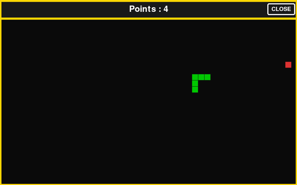
import pygame import sys import os import select import random def get_cmd(): if select.select([sys.stdin], [], [], 0)[0]: return sys.stdin.readline().strip().upper() return None def close_game(): pygame.quit() os._exit(0) pygame.init() pygame.mouse.set_visible(False) # ---------------------------- # SCREEN # ---------------------------- WIDTH, HEIGHT = 1440, 900 screen = pygame.display.set_mode((WIDTH, HEIGHT)) pygame.display.set_caption("Snake Arcade") clock = pygame.time.Clock() FPS = 10 # ---------------------------- # COLORS # ---------------------------- BLACK = (10, 10, 10) WHITE = (255, 255, 255) YELLOW = (255, 215, 0) DARK = (25, 25, 25) GREEN = (0, 200, 0) RED = (220, 50, 50) # ---------------------------- # LAYOUT # ---------------------------- HUD_HEIGHT = int(HEIGHT * 0.10) GAME_HEIGHT = HEIGHT - HUD_HEIGHT # ---------------------------- # FONTS # ---------------------------- font = pygame.font.SysFont(None, 60) small_font = pygame.font.SysFont(None, 40) big_font = pygame.font.SysFont(None, 90) # ---------------------------- # CLOSE BUTTON (PONG STYLE) # ---------------------------- close_text = small_font.render("CLOSE", True, WHITE) close_rect = close_text.get_rect(center=(WIDTH - 80, HUD_HEIGHT // 2)) close_box = close_rect.inflate(40, 30) # ---------------------------- # GRID # ---------------------------- CELL_SIZE = 30 GRID_W = WIDTH // CELL_SIZE GRID_H = GAME_HEIGHT // CELL_SIZE # ---------------------------- # SNAKE STATE # ---------------------------- snake = [(GRID_W // 2, GRID_H // 2)] direction = (1, 0) pending_direction = direction points = 0 game_over = False # ---------------------------- # GAME OVER TIMER (NEW) # ---------------------------- game_over_time = None GAME_OVER_DELAY = 3000 # 3 seconds def spawn_apple(): while True: pos = (random.randint(0, GRID_W - 1), random.randint(0, GRID_H - 1)) if pos not in snake: return pos apple = spawn_apple() def draw_cell(pos, color): x, y = pos pygame.draw.rect( screen, color, (x * CELL_SIZE, HUD_HEIGHT + y * CELL_SIZE, CELL_SIZE - 2, CELL_SIZE - 2) ) # ---------------------------- # MAIN LOOP # ---------------------------- running = True while running: clock.tick(FPS) # ---------------------------- # EVENTS # ---------------------------- for event in pygame.event.get(): if event.type == pygame.QUIT: close_game() if event.type == pygame.MOUSEBUTTONDOWN: mx, my = pygame.mouse.get_pos() if close_box.collidepoint(mx, my): close_game() if event.type == pygame.KEYDOWN: if event.key == pygame.K_ESCAPE: close_game() cmd = get_cmd() # ---------------------------- # INPUT + GAME LOGIC # ---------------------------- if not game_over: # EMERGENCY EXIT COMMAND if cmd == "RASP": running = False if cmd == "UP" and direction != (0, 1): pending_direction = (0, -1) elif cmd == "DOWN" and direction != (0, -1): pending_direction = (0, 1) elif cmd == "LEFT" and direction != (1, 0): pending_direction = (-1, 0) elif cmd == "RIGHT" and direction != (-1, 0): pending_direction = (1, 0) elif cmd == "STOP": pending_direction = direction elif cmd == "CLOSE": close_game() direction = pending_direction # ---------------------------- # MOVE SNAKE # ---------------------------- head_x, head_y = snake[0] dx, dy = direction new_head = (head_x + dx, head_y + dy) # WALL COLLISION if new_head[0] < 0 or new_head[0] >= GRID_W or new_head[1] < 0 or new_head[1] >= GRID_H: game_over = True game_over_time = pygame.time.get_ticks() # SELF COLLISION elif new_head in snake: game_over = True game_over_time = pygame.time.get_ticks() else: snake.insert(0, new_head) if new_head == apple: points += 1 apple = spawn_apple() else: snake.pop() # ---------------------------- # AUTO CLOSE AFTER 3 SECONDS # ---------------------------- if game_over and game_over_time is not None: if pygame.time.get_ticks() - game_over_time > GAME_OVER_DELAY: close_game() # ---------------------------- # DRAW # ---------------------------- screen.fill(BLACK) # HUD pygame.draw.rect(screen, DARK, (0, 0, WIDTH, HUD_HEIGHT)) score_text = font.render(f"Points : {points}", True, WHITE) screen.blit(score_text, score_text.get_rect(center=(WIDTH // 2, HUD_HEIGHT // 2))) # Close button pygame.draw.rect(screen, WHITE, close_box, 5, border_radius=8) screen.blit(close_text, close_rect) # Border pygame.draw.rect(screen, YELLOW, screen.get_rect(), 10) pygame.draw.line(screen, YELLOW, (0, HUD_HEIGHT), (WIDTH, HUD_HEIGHT), 10) # Apple draw_cell(apple, RED) # Snake for segment in snake: draw_cell(segment, GREEN) # ---------------------------- # GAME OVER UI (PONG STYLE) # ---------------------------- if game_over: text = big_font.render("GAME OVER", True, YELLOW) rect = text.get_rect(center=(WIDTH // 2, HUD_HEIGHT + GAME_HEIGHT // 2)) box = rect.inflate(80, 50) pygame.draw.rect(screen, WHITE, box, 6, border_radius=12) pygame.draw.rect(screen, BLACK, box.inflate(-10, -10), 0, border_radius=12) screen.blit(text, rect) pygame.display.flip() pygame.quit() sys.exit() -
Inputs check
Program that lets me test the inputs and make sure everything is read correctly.
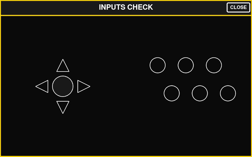
import pygame import sys import os import select import time def get_cmd(): if select.select([sys.stdin], [], [], 0)[0]: return sys.stdin.readline().strip().upper() return None def close_game(): pygame.quit() os._exit(0) pygame.init() pygame.mouse.set_visible(False) # ---------------------------- # SCREEN # ---------------------------- WIDTH, HEIGHT = 1440, 900 screen = pygame.display.set_mode((WIDTH, HEIGHT)) pygame.display.set_caption("Control Interface") clock = pygame.time.Clock() FPS = 60 # ---------------------------- # COLORS # ---------------------------- BLACK = (10, 10, 10) WHITE = (255, 255, 255) YELLOW = (255, 215, 0) DARK = (25, 25, 25) GREEN = (0, 220, 0) RED = (220, 50, 50) BLUE = (80, 160, 255) CYAN = (0, 255, 255) # ---------------------------- # LAYOUT # ---------------------------- HUD_HEIGHT = int(HEIGHT * 0.10) MAIN_HEIGHT = HEIGHT - HUD_HEIGHT LEFT_WIDTH = int(WIDTH * 0.5) RIGHT_WIDTH = WIDTH - LEFT_WIDTH # ---------------------------- # FONT # ---------------------------- font = pygame.font.SysFont(None, 60) small_font = pygame.font.SysFont(None, 40) # ---------------------------- # CLOSE BUTTON # ---------------------------- close_text = small_font.render("CLOSE", True, WHITE) close_rect = close_text.get_rect(center=(WIDTH - 80, HUD_HEIGHT // 2)) close_box = close_rect.inflate(40, 30) # ---------------------------- # HELPERS # ---------------------------- def draw_circle(x, y, r, color, width=3): pygame.draw.circle(screen, color, (x, y), r, width) def draw_filled_circle(x, y, r, color): pygame.draw.circle(screen, color, (x, y), r) def draw_arrow(x, y, direction, size=35, color=WHITE, filled=False): if direction == "UP": pts = [(x, y - size), (x - size, y + size), (x + size, y + size)] elif direction == "DOWN": pts = [(x, y + size), (x - size, y - size), (x + size, y - size)] elif direction == "LEFT": pts = [(x - size, y), (x + size, y - size), (x + size, y + size)] elif direction == "RIGHT": pts = [(x + size, y), (x - size, y - size), (x - size, y + size)] else: return pygame.draw.polygon(screen, color, pts, 0 if filled else 3) # ---------------------------- # POSITIONS # ---------------------------- # Left arrows center_x = LEFT_WIDTH // 2 center_y = HUD_HEIGHT + MAIN_HEIGHT // 2 offset = 120 arrows = { "UP": (center_x, center_y - offset), "DOWN": (center_x, center_y + offset), "LEFT": (center_x - offset, center_y), "RIGHT": (center_x + offset, center_y), } pb_circle = (center_x, center_y) # Right circles (A-F) circle_radius = 45 right_start_x = LEFT_WIDTH + RIGHT_WIDTH // 2 - 180 right_start_y = HUD_HEIGHT + MAIN_HEIGHT // 2 - 120 spacing = 160 row_shift = spacing // 2 circles = { "A": (right_start_x + 0 * spacing, right_start_y), "B": (right_start_x + 1 * spacing, right_start_y), "C": (right_start_x + 2 * spacing, right_start_y), "D": (right_start_x + 0 * spacing + row_shift, right_start_y + spacing), "E": (right_start_x + 1 * spacing + row_shift, right_start_y + spacing), "F": (right_start_x + 2 * spacing + row_shift, right_start_y + spacing), } # ---------------------------- # ACTIVE STATES (timed pulses) # ---------------------------- ACTIVE_TIME = 0.3 # seconds active_until = {} def activate(key): active_until[key] = time.time() + ACTIVE_TIME def is_active(key): return active_until.get(key, 0) > time.time() # ---------------------------- # MAIN LOOP # ---------------------------- running = True while running: clock.tick(FPS) # cleanup expired now = time.time() active_until = {k: v for k, v in active_until.items() if v > now} for event in pygame.event.get(): if event.type == pygame.QUIT: close_game() if event.type == pygame.MOUSEBUTTONDOWN: if close_box.collidepoint(pygame.mouse.get_pos()): close_game() if event.type == pygame.KEYDOWN: if event.key == pygame.K_ESCAPE: close_game() cmd = get_cmd() if cmd: # EMERGENCY EXIT COMMAND if cmd == "RASP": running = False # arrows if cmd in ["UP", "DOWN", "LEFT", "RIGHT"]: activate(cmd) # center PB elif cmd == "PB": activate("PB") # right grid elif cmd in ["A", "B", "C", "D", "E", "F"]: activate(cmd) elif cmd == "CLOSE": close_game() # ---------------------------- # DRAW # ---------------------------- screen.fill(BLACK) # HUD pygame.draw.rect(screen, DARK, (0, 0, WIDTH, HUD_HEIGHT)) text = font.render(f"INPUTS CHECK", True, WHITE) screen.blit(text, text.get_rect(center=(WIDTH // 2, HUD_HEIGHT // 2))) # close pygame.draw.rect(screen, WHITE, close_box, 5, border_radius=8) screen.blit(close_text, close_rect) pygame.draw.line(screen, YELLOW, (0, HUD_HEIGHT), (WIDTH, HUD_HEIGHT), 6) # ---------------------------- # LEFT SIDE (ARROWS + PB) # ---------------------------- for name, pos in arrows.items(): draw_arrow( pos[0], pos[1], name, color=CYAN if is_active(name) else WHITE, filled=is_active(name) ) # center PB circle draw_filled_circle( pb_circle[0], pb_circle[1], 60, GREEN if is_active("PB") else DARK ) draw_circle(pb_circle[0], pb_circle[1], 60, WHITE) # ---------------------------- # RIGHT SIDE (A-F circles) # ---------------------------- for key, pos in circles.items(): color = RED if is_active(key) else BLUE if is_active(key): draw_filled_circle(pos[0], pos[1], circle_radius, color) draw_circle(pos[0], pos[1], circle_radius, WHITE) pygame.draw.rect(screen, YELLOW, screen.get_rect(), 8) pygame.display.flip() pygame.quit() sys.exit() -
USB test
Program that lets me see what data the Raspberry Pi Pico sends.
import serial import time # ---------------------------- # USB SERIAL PORT (your device) # ---------------------------- PORT = "/dev/serial/by-id/usb-MicroPython_Board_in_FS_mode_de6258c0c3143639-if00" BAUD = 115200 # ---------------------------- # Actions (replace with your real logic) # ---------------------------- def button_a(): print("A") def button_b(): print("B") def button_c(): print("C") def button_d(): print("D") def button_e(): print("E") def button_f(): print("F") def button_close(): print("CLOSE") def button_menu(): print("MENU") def button_left(): print("LEFT") def button_right(): print("RIGHT") def button_up(): print("UP") def button_down(): print("DOWN") def button_pb(): print("PB") # ---------------------------- # Command map # ---------------------------- commands = { "A": button_a, "B": button_b, "C": button_c, "D": button_d, "E": button_e, "F": button_f, "CLOSE": button_close, "MENU": button_menu, "LEFT": button_left, "RIGHT": button_right, "UP": button_up, "DOWN": button_down, "PB": button_pb, } # ---------------------------- # Connect to Pico # ---------------------------- print("Connecting to Pico...") ser = serial.Serial(PORT, BAUD, timeout=1) time.sleep(2) # allow Pico reset print("Connected to Pico!") # ---------------------------- # Main loop # ---------------------------- while True: try: line = ser.readline().decode("utf-8").strip().upper() if line: if line in commands: commands[line]() else: print("Unknown command:", line) except Exception as e: print("Error:", e) time.sleep(0.1) -
System startup
I also modified some files in the Pi to make it so on startup, it displays a custom made splashscreen instead of the default Raspberry splashscreen and when everything is ready it launches the interface program immediately.
The splashscreen was made on Inkscape :

To replace the default splashscreen by the custom one, I place the picture in the desktop and type on the terminal :
                    sudo apt install plymouth plymouth-themes
                    sudo cp my_splash.png /usr/share/plymouth/themes/pix/splashscreen.png
To start on the interface on startup :
sudo nano /etc/systemd/system/arcageddon.serviceThis opens a new windows, I have to type and save the following :
                    [Unit]
                    Description=Arcageddon UI
                    After=graphical.target
                    Wants=graphical.target

                    [Service]
                    User=fabio
                    WorkingDirectory=/home/fabio/Desktop/MicroPython_codes
                    Environment=DISPLAY=:0
                    Environment=XAUTHORITY=/home/fabio/.Xauthority
                    ExecStartPre=/bin/sleep 5
                    ExecStart=/usr/bin/python3 /home/fabio/Desktop/MicroPython_codes/interface.py
                    Restart=no

                    [Install]
                    WantedBy=graphical.target
And finally, I have to enable it :
sudo systemctl enable arcageddon.serviceCurrently, on startup, the monitor first shows my splashscreen, then opens on the Pi desktop and after 5-10 seconds, my interface opens up.
Bill Of Materials
| Item | Quantity | Unity price [€] |
| Wood plank (12mm) | NA | ~25,00 |
| Paint canister (black) | 2 | 2,33 |
| Monitor (19 inches) | 1 | NA |
| Raspberry Pi 5 4GB RAM starter kit | 1 | 215,00 |
| Raspberry Pi Pico | 1 | ~4,00 |
| Joystick | 1 | 2,66 |
| Keyboard switch | 8 | 0,86 |
| SMD resistor (1206) | 9 | NA |
| SMD capacitor (1206) | 12 | NA |
| HDMI coupler | 1 | 6,45 |
| USB-A to USB-C cable | 1 | 13,95 |
| VGA to HDMI cable | 1 | ~10,00 |
| Power cord | 1 | ~10,00 |
Final result
Slide
Video
Useful file(s) (Click to download)
- Joystick module (KiCad)
- Buttons module (KiCad)
- Button right module (KiCad)
- Button left module (KiCad)
- Microcontroller module (KiCad)
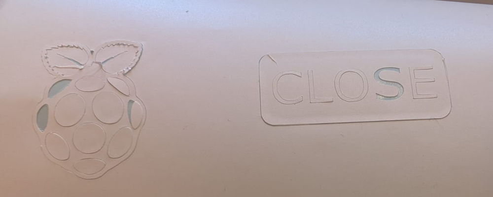
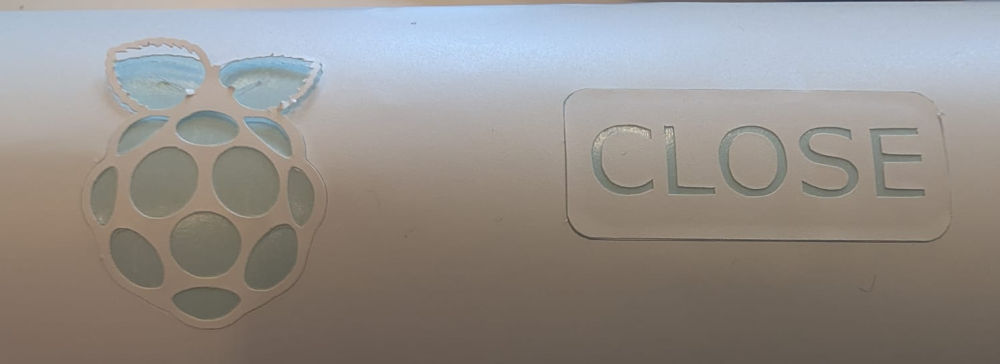
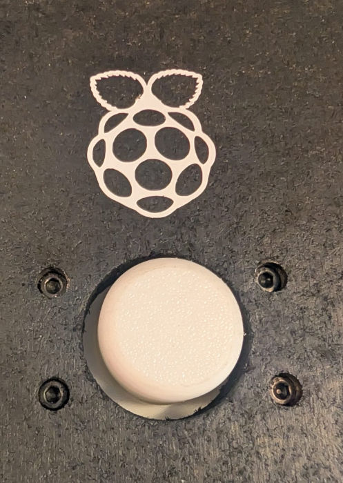
- Close button - Vinyl design (Inkscape)
- Raspberry button - Vinyl design (Inkscape)
- Splashscreen (Inkscape)
- Back door pieces (Autodesk Fusion)
- Buttons and joystick pieces (Autodesk Fusion)
- Raspberry holder (Autodesk Fusion)
- Arcade machine pieces (Autodesk Fusion)
- Controller - MicroPython code (Thonny)
- Interface - Python code (Thonny)
- USB data - Python code (Thonny)
- Game 1 (Ping) - Python code (Thonny)
- Game 2 (Cobra) - Python code (Thonny)
- Inputs check - Python code (Thonny)
- USB communication test - Python code (Thonny)
PCB modules
2D
3D
Codes
Assignments checklist
- ✅Made your slide 1920 x 1080 pixels with your name, project name, Fab Lab name, a photo/render/sketch of your project, a brief description of what your project is/does.
- ✅Made a ~1 minute (25MB/1080p) video of your final project showing its fabrication and functionality.
- ✅Made a separate Final Project page that summarizes/documents your project.
- ✅Included the BOM (Bill of Materials) for your project.
- ✅Linked from this page to any weeks that you worked on your final project.
- ✅Documented how you implemented system integration in your final project.
- ✅Linked to your presentation.png and presentation.mp4; make sure they are located to the root of your website.
- ✅Included all of your original design files in the archive (2D & 3D, board files & code). No external hosting of final project files - discuss file sizes with your instructor.
- ✅Included the license you chose.
- ✅Acknowledged work done by others.