Prior knowledge
|
I have a lot of experience with C and C++ languages, mainly with arduino and the ATmega328P, and basic knowledge in the assembly and python languages. |
Hero shot
Languages
Like human language, there are a lot of programming languages, each with their pros and cons, here are a few with a simple explanation :
-
C
Gives you direct control over memory and hardware, you usually work with a datasheet to code with C.
-
C++
An extension of C that is simplified, easier to read and understand and usually has fewer lines than C.
-
Python
High-level, easy-to-read language designed for rapid development.
-
MicroPython
Lightweight version of Python made for microcontrollers.
Datasheet analysis
Analyzing a datasheet is very important, in a general way, a datasheet possesses every information about your component, tool, ... about different aspects like dimensions, electrical characteristics, packages and many more and can sometimes be difficult to understand or find a specific information.
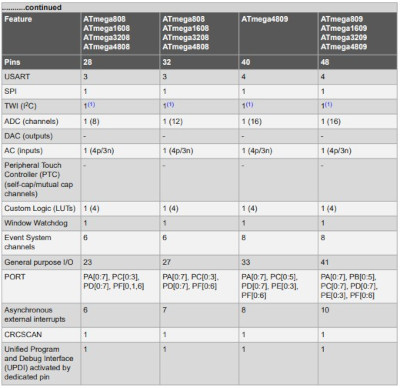
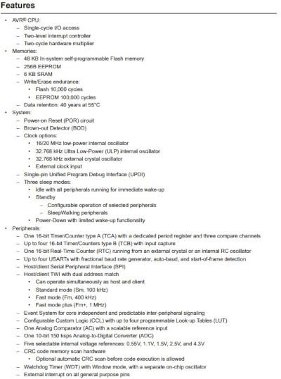
For a microprocessor, a datasheet allows to see pinouts, diagrams, electrical characteristics, registers, dimensions, and a lot more, for example, the datasheet we will analyze is about the ATMega4809, created by Microchip Technology and currently the microprocessor of the Arduino Nano Every, which measures 7x7x1 mm and has 560 pages (datasheet).
By watching the Peripheral Overview (page 2 and 3), the Features (page 5 and 6) and the Table of Contents (page 6 to 11), we can see the main functions the microprocessor can offer : ports, ADCs, timers, communication buses, ACs, ...
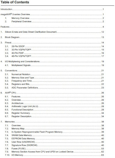
By selecting a specific chapter, we can see the complete details of a function, let's take an example : chapter 16. PORT - I/O Pin Configuration which starts at page 147, usually the first chapter you explore when starting with a new microprocessor or microcontroller and want to code in its base language, in this case, in C.
This chapter explains how to initialize a pin, program it as input or output, give it a high or low value, its interrupts and its registers, which are the most important parameters to setup the microprocessor and it's pins, a register is usually composed of 8 bits, each corresponding to one pin, some have less due to being a specific function, you mainly use '0' and '1' to modify them.
Let's take for example the registers Data Direction (page 154), Data Direction Toggle (page 157) and Output Value (page 158).
-
Data Direction
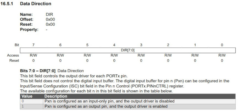
Like the name suggests, this register sets a pin as an input or output depending on the value you put on the register with '0' making the pin an input and '1' making it an output.
-
Data Direction Toggle
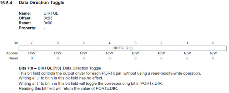
This register will toggle the direction of a pin if you put '1' to it, it basically changes an input into an output and vice versa.
-
Output Value
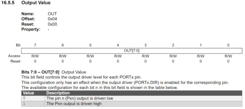
This register sets the value of a pin to high or low.
IDE (Integrated Development Environment)
These serve as an interface to make your code and send it to your board, there are a lot of them, some who focus a specific language or others where you can code different languages.
They all have their own way of working, some being easier and other being more difficult to understand or use.
Here are some popular ones : Arduino IDE, Thonny, Visual Studio, Visual Studio Code, ...
By experience, the most annoying thing is usually how to connect a board to a computer, it can sometimes be extremely easy and fast but it can also be really long to understand how to connect them together.
First tests
To begin, I'll try the MicroPython language (I never used it and I only have basic knowledge of Python).
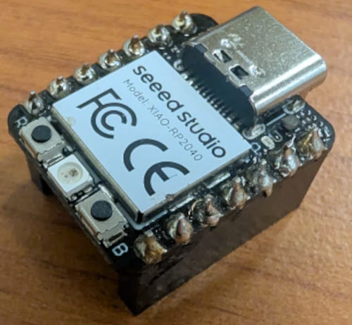
For the first tests, I'll use the SEEED Studio XIAO RP2040 development board, provided by my FabLab instructor.
It is a small yet powerful microcontroller, it offers 14 GPIO pins with different functions : 11 digital pins, 4 analog pins, 11 PWM Pins, 1 I2C interface, 1 UART interface and 1 SPI interface.
Before that, I need to connect and communicate to the board with my computer, for that, I follow step by step Nicolas De Coster's tutorial as well as the constructor of the board's tutorial.
First, I must install Python, then open a command prompt and type : pip install thonny, this will install packages necessary for the IDE we will use to code in MicroPython.
Then, concerning the IDE, I must install Thonny, which is a Python IDE for beginners.
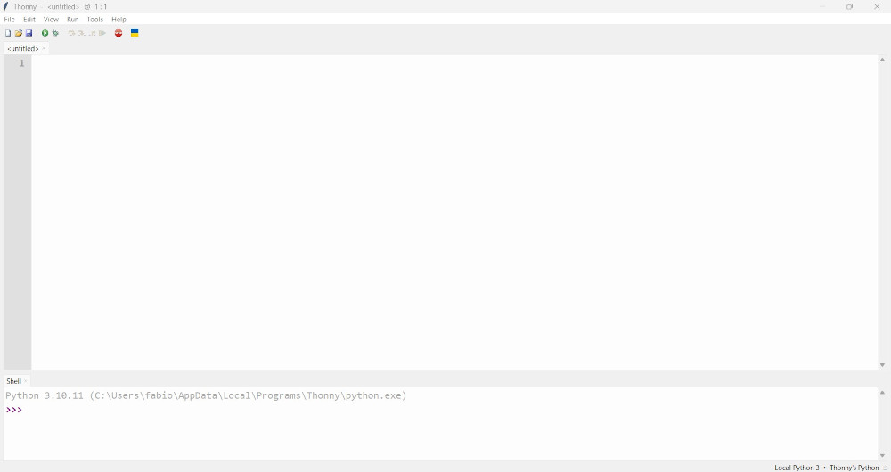
Upon opening Thonny, I select Tools, then Options... and finally Interpreter.
For the interpreter, I select MicroPython (RP2040) and then Install or update MicroPython.
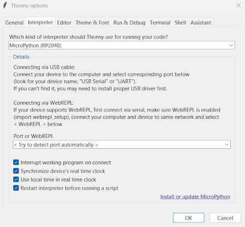
A new windows appears to connect to the board.
On the board, I press the boot button while connecting the USB cable to my computer, this will make a new volume appear on my computer (usually RPI-RP2), I select this volume on the new window for Target volume and choose the variant Raspberry Pi - Pico / Pico H and click Install.
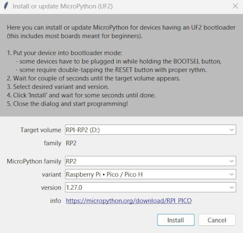
My board is successfully connected and I can start to send code.
To know what GPIOs and functions are available, I used the constructor of the board's site.
-
Led blinking
Simple code in MicroPython to make the built-in led of the XIAO RP2040 blink.
########################### ### Code in MicroPython ### ########################### import machine # For hardware functions import time # For time functions led = machine.Pin(25, machine.Pin.OUT) # Set pin 25 (built-in led on XIAO RP2040) as an output while True: # Infinite loop led.toggle() # Change the led's status time.sleep(0.5) # Delay -
RGB Led show
Simple code in MicroPython to make the built-in RGB led of the RP2040 change colors.
I first had to download the library to control the built-in RGB led on Github by Jan Bednarik (a library is composed of different functions to simplify and give better visibility for a code).
Then, with Thonny, open and save the library in the microcontroller by selecting File then Save As..., choose RP2040 deviceand name it : ws2812.py.
                                            ###########################
                                            ### Code in MicroPython ###
                                            ###########################

                                            import time					# For time functions
                                            import machine				# For hardware functions
                                            from ws2812 import WS2812	# For RGB Led

                                            # RGB colors values (R, G, B)
                                            BLACK = (0, 0, 0)
                                            RED = (255, 0, 0)
                                            YELLOW = (255, 150, 0)
                                            GREEN = (0, 255, 0)
                                            CYAN = (0, 255, 255)
                                            BLUE = (0, 0, 255)
                                            PURPLE = (180, 0, 255)
                                            WHITE = (255, 255, 255)

                                            COLORS = (BLACK, RED, YELLOW, GREEN, CYAN, BLUE, PURPLE, WHITE)	# List of colors

                                            led = WS2812(23,1)	# built-in RGB led on XIAO RP2040 with the pin it is attached to (GPIO25) and the number of leds (1 led)

                                            print("Multiple colors")	# Print on shell

                                            while True:						# Infinite loop
                                                for color in COLORS:		# Goes through each color in the list COLORS
                                                    led.pixels_fill(color)	# Changes the color for the led
                                                    led.pixels_show()		# Sends the color data to the Led
                                                    time.sleep(0.5)			# Delay
Same test in MicroPython and C++
I'm am now going to do the same test for different languages.
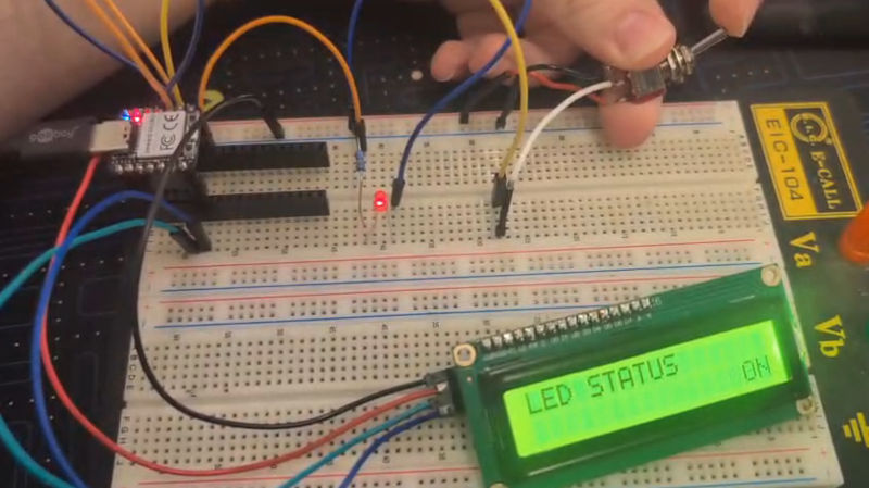
The test consists of one button, one led, a I²C LCD screen and a microcontroller. Depending what the button reads, the led will toggle ON or OFF and the screen will display the current status of the Led.
The I²C LCD screen has an additional special board to simplify the wiring so that we only need 4 wires : VCC, GND, SDA and SCL (the last 2 are related to I²C which is a serial communication bus that we will use).
-
C++ with an Arduino Nano Every in the Arduino IDE
I first followed a tutorial to connect the screen to the Arduino.
To control the I²C LCD screen, I needed to install a library on Arduino IDE, I simply go to LIBRARY MANAGER, search for LiquidCrystal I2C by Frank de Brabander and click INSTALL.
///////////////////////////////////// //////////// Code in C++ //////////// ///////////////////////////////////// #include <Wire.h> // Library to use I²C communication #include <LiquidCrystal_I2C.h> // Library to use the I²C LCD screen LiquidCrystal_I2C lcd(0x27, 16, 2); // Function to name and give the parameters of the I²C LCD screen int led = 2; // Pin of the led int button = 3; // Pin of the button int buttonValue; // Value of the button void setup() { lcd.init(); // Initialization of the I²C LCD screen lcd.backlight(); // To enable the backlight of the I²C LCD screen lcd.setCursor(0, 0); // First line of the I²C LCD screen lcd.print("LED STATUS"); // Message of the first line of the I²C LCD screen pinMode(led, OUTPUT); // The led is configured as an OUTPUT pinMode(button, INPUT); // The button is configured as an INPUT } void loop() { buttonValue = digitalRead(button); //Reading of the value of the button if (buttonValue == 1) { // If the button is ON digitalWrite(led, HIGH); // The led turns ON lcd.setCursor(0, 1); // Second line of the I²C LCD screen lcd.print(" ON"); // Message to display to the I²C LCD screen } else { // If the button is OFF digitalWrite(led, LOW); // The led turns OFF lcd.setCursor(0, 1); lcd.print(" OFF"); } } -
MicroPython with a SEEED Studio XIAO RP2040 in the Thonny IDE
To control the I²C LCD screen, I asked the help of ChatGPT and just like the built-in RGB led, I had to download 2 libraries from Github and save them into the microcontroller : library 1 and library 2.
I added additional line of codes in the first library for the screen to work well.
                                        ###########################
                                        ### Code in MicroPython ###
                                        ###########################

                                        from machine import Pin, I2C	# For hardware functions
                                        from i2c_lcd import I2cLcd		# For I²C LCD functions
                                        import time						# For time functions

                                        i2c = I2C(1, sda=Pin(6), scl=Pin(7), freq=400000)	# Initialize I2C for SEEED XIAO RP2040 (SDA=6, SCL=7)
                                        I2C_ADDR = 0x27										# I²C LCD address found from scan
                                        lcd = I2cLcd(i2c, I2C_ADDR, 2, 16)					# Function to name and give the parameters of the I²C LCD screen

                                        lcd.move_to(0, 0)			# First line of the I²C LCD screen
                                        lcd.putstr("LED STATUS")	# Message to display to the I²C LCD screen

                                        led = Pin(2, Pin.OUT)	# Configure pin 2 as an output
                                        button = Pin(4, Pin.IN)	# Configure pin 4 as an input

                                        while True:								# Infinite loop
                                            buttonValue = button.value()		# Reading of the value of the button
                                            if buttonValue == 1:				# If the button is ON
                                                led.value(1)					# The led turns ON
                                                lcd.move_to(1, 0)				# Second line of the I²C LCD screen
                                                lcd.putstr("              ON")	# Message to display to the I²C LCD screen
                                            else:								# If the button is OFF ('0')
                                                led.value(0)					# The led turns OFF
                                                lcd.move_to(1, 0)				# Second line of the I²C LCD screen
                                                lcd.putstr("             OFF")	# Message to display to the I²C LCD screen
Problem(s) met
-
USB cable
To establish the connection with the XIAO RP2040, I needed a USB cable, but the one I had didn't seem to work, I realized it didn't transmit data, only power, so I had to use another one.
-
I²C LCD screen library
The first tutorials with the I²C LCD screen and MicroPython didn't work and Thonny always gave me an error message saying one of the libraries wasn't recognized.
It was because that missing library was not present on Windows and could only be installed on Linux, so I asked ChatGPT and I discovered there were special libraries made for MicroPython to use on Windows.
Useful file(s) (Click to download)
- C++ code for the led, button and I²C LCD screen test (Arduino IDE)
- MicroPython code for the blinking led (Thonny)
- MicroPython code for the RGB led show (Thonny)
- MicroPython code for the led, button and I²C LCD screen test (Thonny)
- Library for the built-in RGB led (Thonny)
- Library n°1 for the I²C LCD screen (Thonny) (modified for I2C LCD screen to work)
- Library n°2 for the I²C LCD screen (Thonny)
Assignments checklist
- ✅Linked to the group assignment page.
- ✅Browsed and documented some information from a microcontroller's datasheet.
- ✅Programmed a board to interact and communicate.
- ✅Described the programming process(es) you used.
- ✅Included your source code.
- ✅Included hero shot(s).