Prior knowledge
|
I have ~100 hours on laser cutter machines since 2-3 years, mainly for my work. The experiences I've had are mostly engraving and a bit of cutting. |
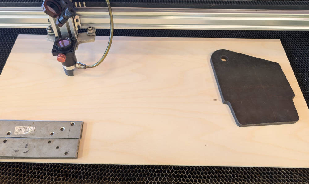
Hero shot
Laser cutter machine
My FabLab possesses 3 models of laser cutter machines :
-
Epilog Fusion Pro 32
Laser : CO2
Laser power : 60W
Work area : 914 x 610 x 228mm
-
BRM PRO 1300
Laser : CO2
Laser power : 150W
Work area : 1300 x 900 x 200mm
-
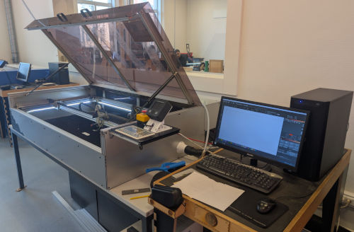
Lasersaur (DIY and OS)
Laser : CO2
Laser power : 100W
Work area : 1220 x 610mm
The machines have integrated securities in case someone opens the case while there is a work, it should pause or turn off the laser.
In case of a fire, there is a fire extinguisher and a fire blanket in the room where the laser cutters are.
It is recommended to not look at the laser directly while there is a work but just in case, there are protective glasses close to the machines.
After following the formation and the security protocols for the Lasersaur, we can start our first tests. By "we", I am talking about the 2 others Fab Academy 2026 students that are in the same FabLab as me : Michel Osée and Jonas Grimaud.
Before the tests, let's talk about the Lasersaur and the software used to export the files to the machine.
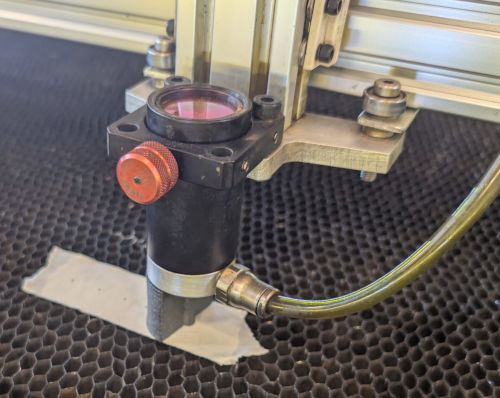
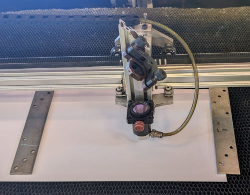
The lasersaur is a DIY kit laser cutter machine, it's initial laser power is 150W but can go down to 100W if it has a long life or use.
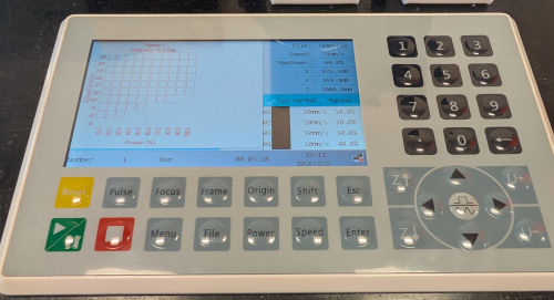
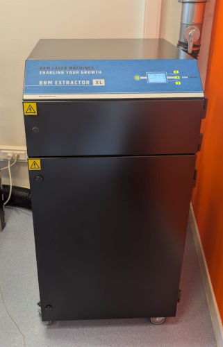
It has it's own computer, emergency stop button and control panel directly connected to it as well as an extractor and compressed air for particles and protection.
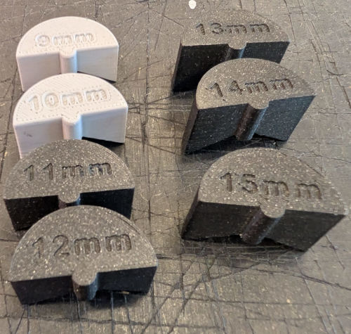
It is important to note that the Lasersaur has no autofocus, for that, the FabLab ULB has created these 3D pieces to have a focus of different height (we will see later how these pieces can change a test) :
The software used to export the files to the machine and then execute a test is Lightburn (Free trial for 30 days then you have to buy a license).
Here's it's interface :
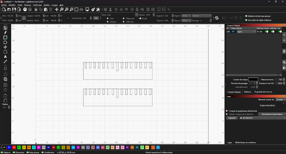
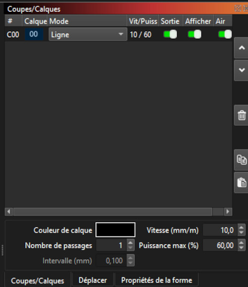
Here's where you can change the main parameters : speed, power, passes, ...
Group assignment
Now for the actual tests, we first discuss about what kind of tests we want to try and then divide the work between each other. The tests we chose are : focus, material, kerf and brush (focus and material needing no setup or files).
-
Focus
To test the focus, we simply put 2 layers of adhesive tape on top of each other and press the Pulse button on the control panel. This will quickly make a point on the adhesive tape. We do this with each 3D pieces that serve a focus support (going from 9mm to 15mm, we later learned that there are more focus pieces).
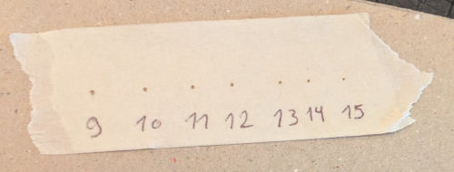
By the look of it, the further the laser is from the material, the more precise it will get but at the cost of less power.
-
Material test
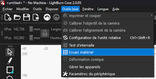
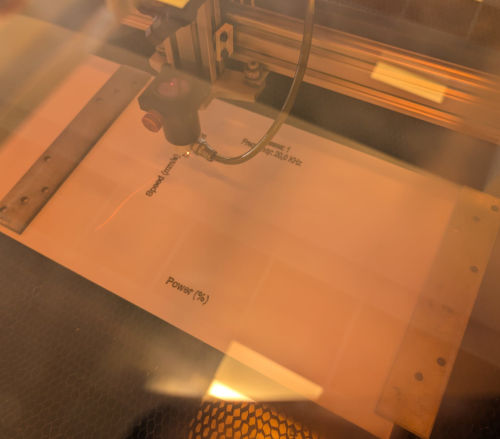
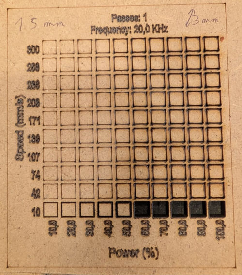
The materials test allows us to see what are the best parameters for laser cutting a material. The software Lightburn possesses a tool to automatically create a grid and change the desired parameters.
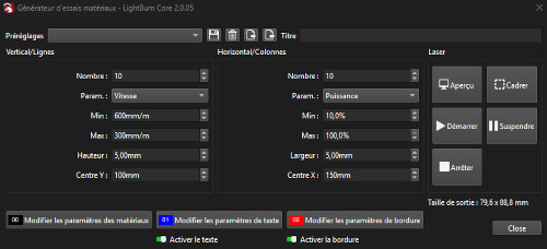
For the tests, we create a grid of 10x10 squares with the speed going from 10 to 300mm/s and the power going from 10 to 100%.
We first try with a material with a thickness of 1mm and two different focuses : 9mm and 15mm to see the difference.
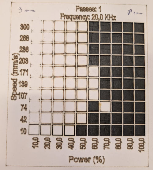
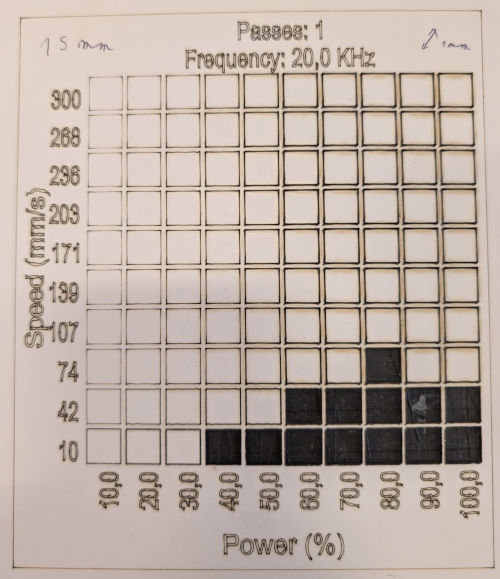
We can see that with a bigger focus, the machine cuts less squares but gets more precise.
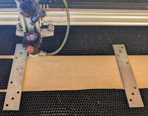
We also tried with a material with a thickness of 3mm and a focus of 15mm.
-
Kerf
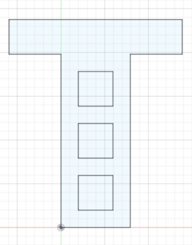
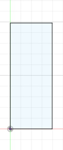
With a material with a thickness of 3mm, we decide to do 2 kerf tests to see how much we lose when laser cutting, the design is simply a big rectangle with 9 little rectangles inside, it was made by Jonas using Inkscape and Python coding.
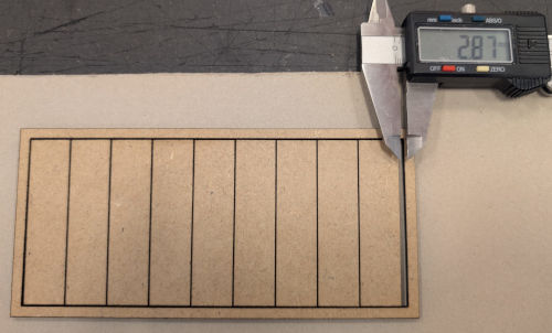
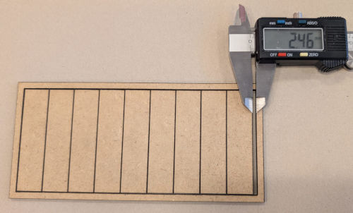
You can see we loose 2.87mm of material on the first test and 2.46mm on the second test.
To calculate the kerf, we add the 2 results (of matter lost) together and divide it by 20 (number of lines between rectangles and extremities) which gives us a kerf of ~0.27mm.
-
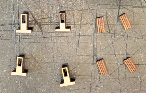
Brush
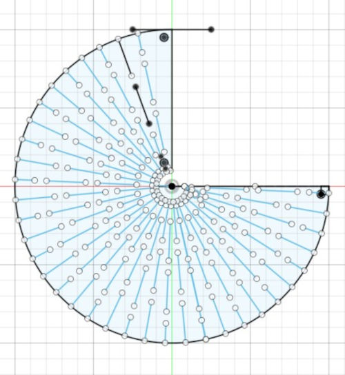
I made the design on Autodesk Fusion, exported it in dxf in Inkscape and then opened it in Lightburn (I realized later that I could have directly imported the dxf file in Lightburn).
The material chosen has a thickness of 3mm, based on that, I have a center hole length of 3mm then going left (towards the minus sign), we loose 0.05mm in hole length and going right (towards the plus sign), we gain 0.05mm in hole length.
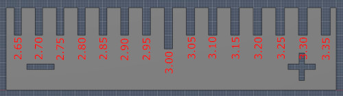
For the laser cutter, I chose the following parameters : speed : 10mm/s, power : 60%, passes : 1 and focus : 15mm based on the previous material test.
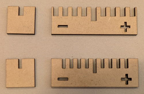
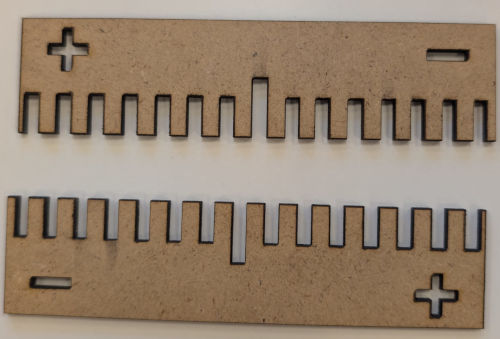
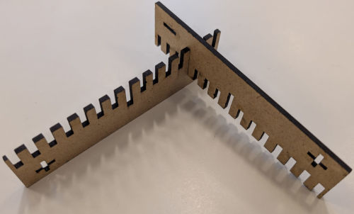
The first test was not very helpful, so for the second test, I simply added more holes, deleted the little piece and duplicated the big piece.
Parametric design
Before starting my construction kit, I'll try to do a simple parametric design, something I've never did before.
I'll simply create a circle with another circle inside and mess with their parameters via the parametric menu.
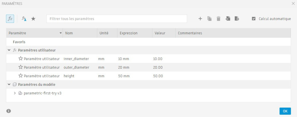
Here's where you can find the parametric menu :
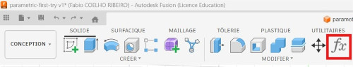
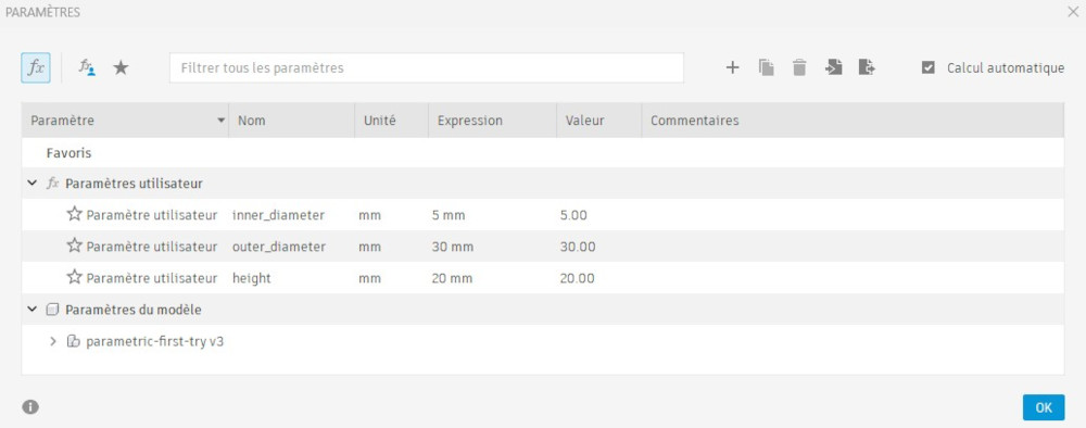
I create 3 parameters : inner_diameter (for the inner circle), outer_diameter (for the outer circle) and height (for the piece).
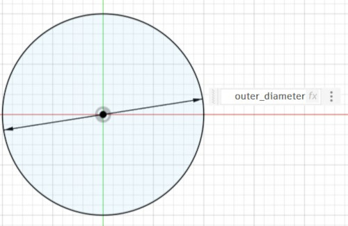
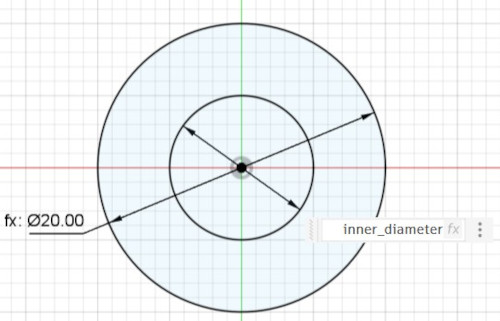
Then, I create a sketch with my 2 circles but instead of typing the values, I type the name of the parametric value.
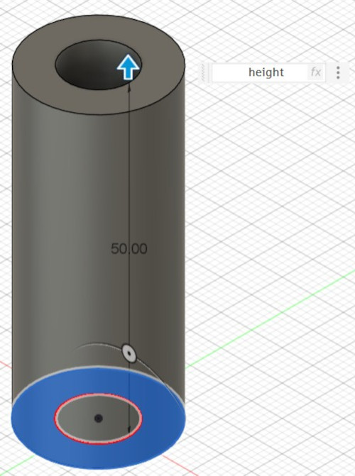
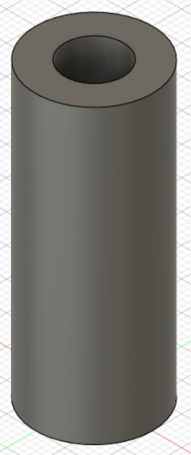
Here's the 3D piece with the first parameters :
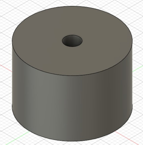
Then, via the parametric menu, I change the values to change the 3D piece without touching the sketch.
Here's the 3D piece with the second parameters :
Construction kit
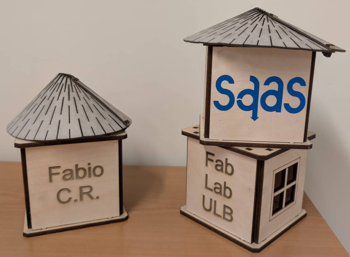
For the construction kit, I decided to make a tower with different walls designs and a bent roof that is cone shaped.
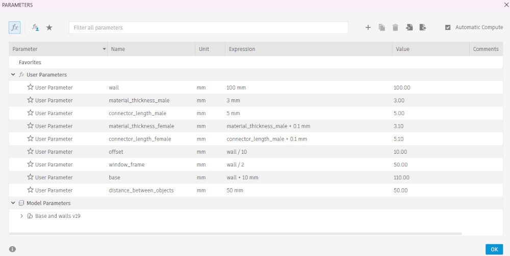
I make the sketches on Autodesk Fusion and give only the walls the possibility to be parametric.
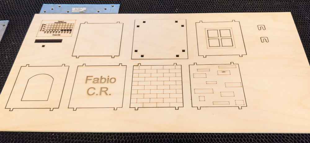
Here are the pieces :
-
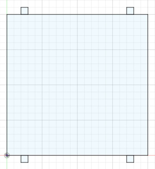
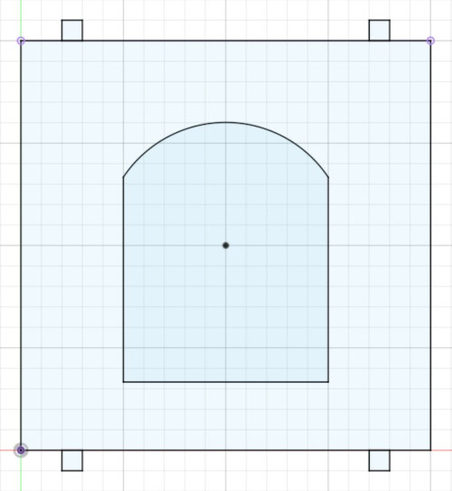
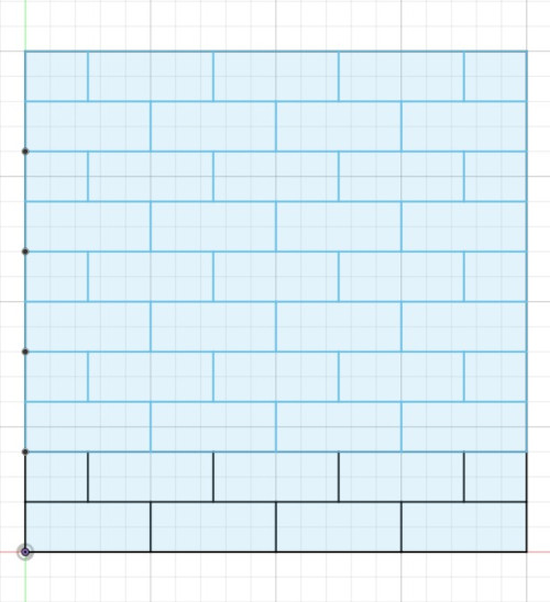
Walls
Walls of the tower (these are parametric and everything in them is calculated to be scaled when changing parameters).
-
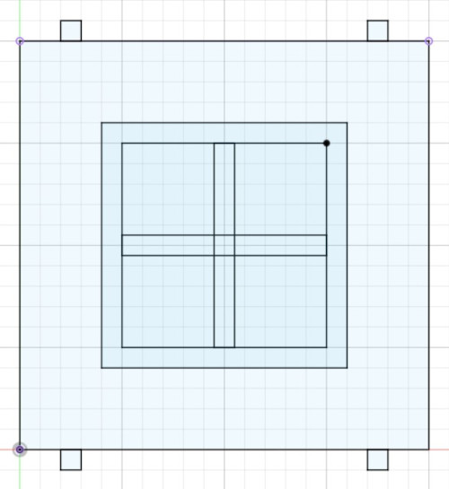
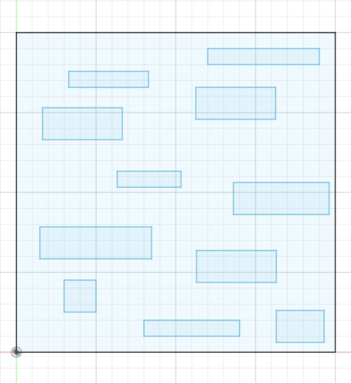
Wall designs
Design to add to the walls like a sticker (these are not parametric, I just use Inkscape to scale them).
-
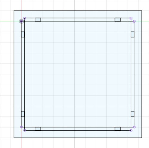
Base
To hold the walls together (like a support).
-
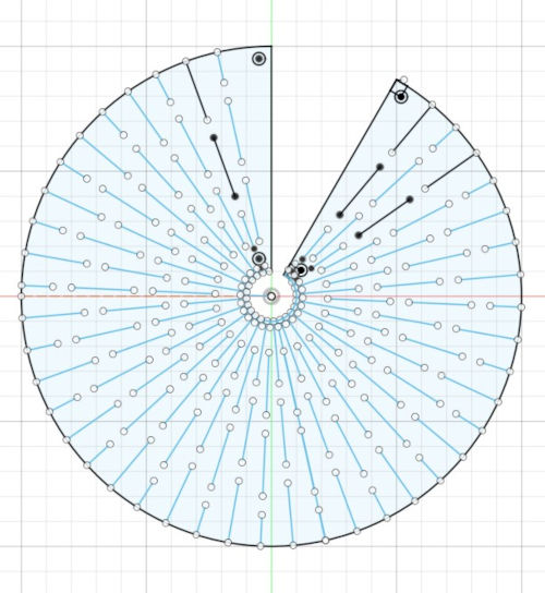
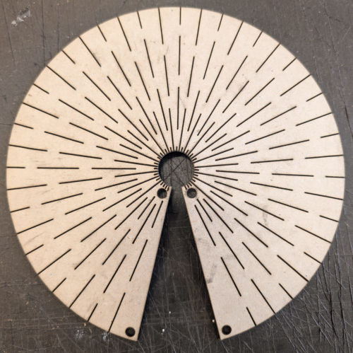
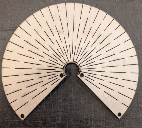
Roofs and roof connectors
2 roofs cone-shaped (with 2 different angles), and the connectors to hold the roof together.
Once every piece is done, I export them all as dxf files in Inkscape and finally laser cut them.
I use a wooden material with a thickness of 5mm for the walls and the base.
The parameters for this material for the cuts are : speed : 10mm/s, power : 80%, passes : 1 and focus : 15mm and for the engravings : speed : 60mm/s, power : 30%, passes : 1 and focus : 15mm.
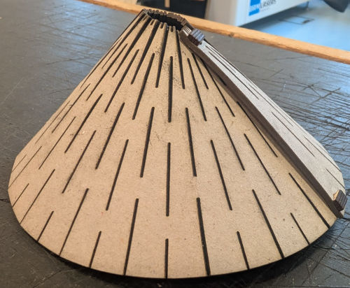
I had trouble to find a good design for the roof-holders, so I ultimately decided to go for a thick and solid piece that will lock the pieces together.
I use a cardboard material with a thickness of 2mm for the roofs.
The parameters for this material for the cuts are : speed : 10mm/s, power : 50%, passes : 1 and focus : 12mm.
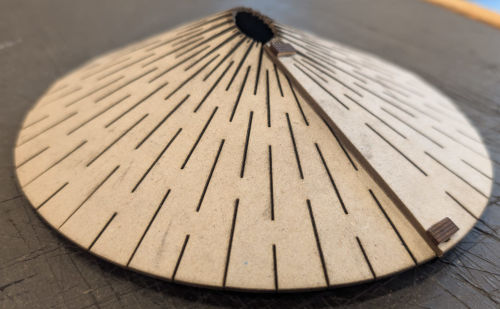
Here's the final assembly :
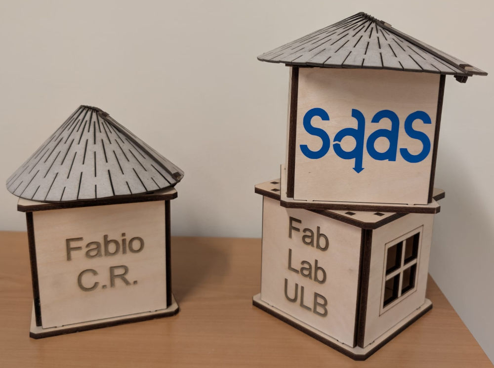
The pieces fit well together and the walls can change location, although if you hold the top base up, some pieces can fall.
Vinyl cutter machine
My FabLab possesses 2 models of vinyl cutter machines :
-
Cameo 3
-
Cameo 4
I focused a bit too much on the laser cutter machine and kinda forgot the vinyl cutter machine, so for the tests, I simply made 2 stickers that would be placed on the empty walls of the construction kit.
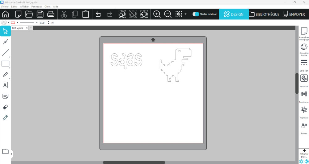
Both models work with the Silhouette Studio software that gives us the possibility to control our design and offers many tools.
I'll do the tests with the Cameo 3 and 2 rolls of sticker of different colors : red and blue.
Each machine has a metallic rod with 4 "holders", 2 at the extremities that will roll the material upwards and 2 in the middle to make sure the material doesn't move. The last 3 can be moved but the first one cannot.
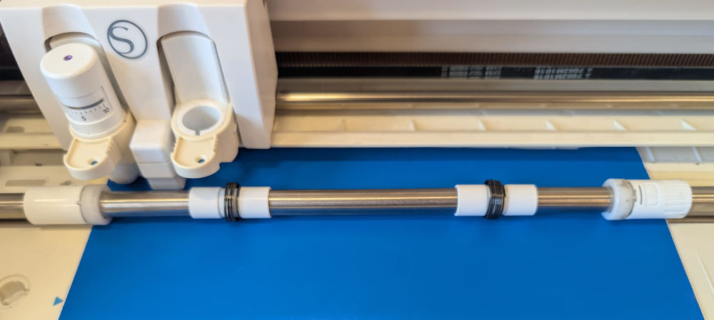
To start a cut, I must insert the material under the holders and move them to be on top of the material.
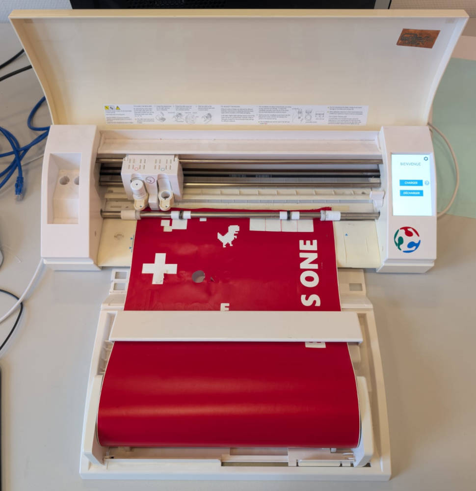
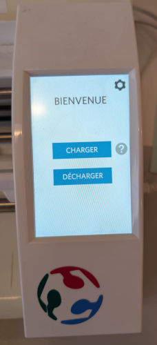
Then on the machine control panel, I press Charger (which means Load) to load the material.
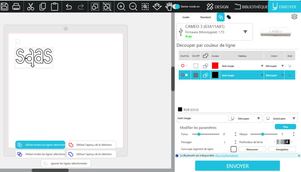
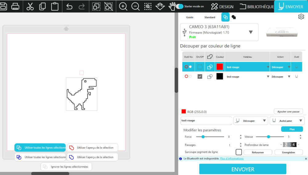
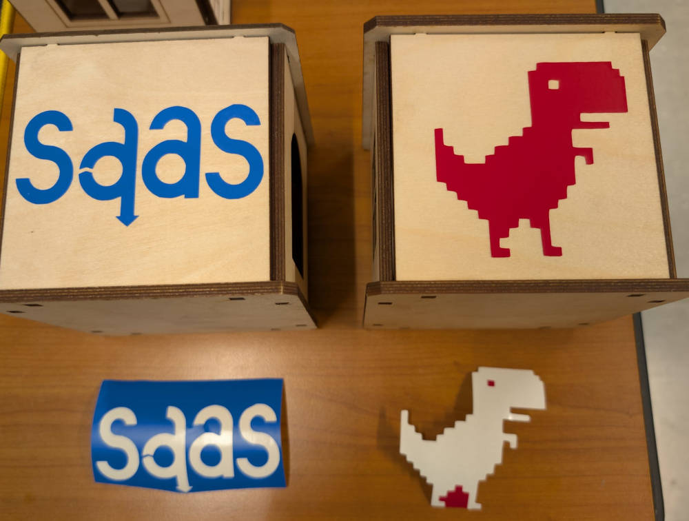
Now on the software, I export my files, one is the logo of the department I work and the other one the Chrome dinosaur.
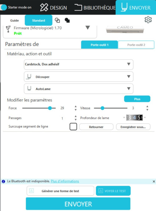
Here is the parameters menu for the machine, the main parameters I mess with are : force (= strength), vitesse (= speed), profondeur de lame (= blade depth) and passages (= passes).
I also use the transform tool the software proposes to scale my designs.
I first try to cut a tiny 1x1 cm square to compare where the cut is made on the physical material and to find the best parameters to cut the material without going all the way through.
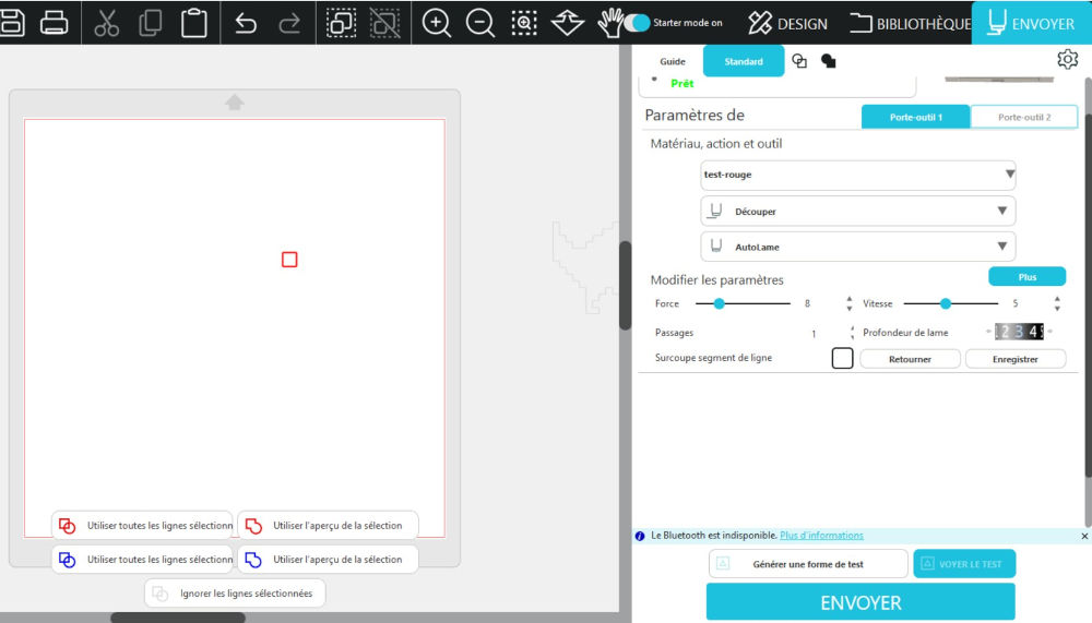
The parameters I choose are : strength : 8, speed : 5, blade depth : 3 and passes : 1.
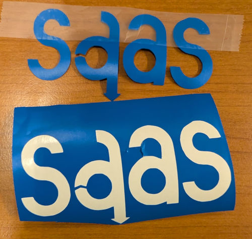
Once I confirm the parameters, I cut my 2 designs.
Here are the final results (I cut around them to take better pictures but I assure you the cuts worked well and didn't go all the way through).
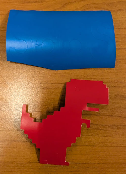
Then to separate the design I want to keep and the waste, I simply use a scotch and then place them on the empty walls of the construction kit.
Problem(s) met
-
Construction kit - Base
When assembling the walls and the base together, I realized I forgot to implement holes for a second floor for the base, but instead of modifying it I simply keep this little house design and if I want to make a tower, I simply stack them on top of each other. The base is complicated to do the parametric way so I'll skip it.
-
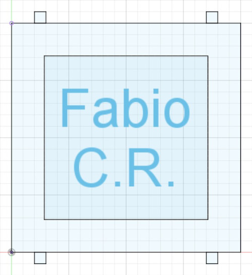
Construction kit - Wall 4 (wall with text)
For some reason, when opening this wall on Inkscape or Lightburn, the text doesn't appear, so I just use the text tool, that both softwares offer, to place a new text.
Useful file(s) (Click to download)
- Laser cutter - Brush 2D file (Inkscape)
- Laser cutter - Brush 3D file (Autodesk Fusion)
- Laser cutter - Kerf 2D file (Inkscape)
- Parametric test 3D file (Autodesk Fusion)
- Construction kit - Base and walls 3D files (Base not parametric) (Autodesk Fusion)
- Construction kit - Roofs and connectors 3D files (Autodesk Fusion)
- Construction kit - Wall designs 3D files (Autodesk Fusion)
- Vinyl cutter - Stickers design (Inkscape)
Assignments checklist
- ✅Linked to the group assignment page.
- ✅Reflected on your individual page what you learned of your labs safety training.
- ✅Explained how you created your parametric design.
- ✅Documented how you made your press-fit construction kit.
- ✅Documented how you made something with the vinyl cutter.
- ✅Included your original design files.
- ✅Included hero shots of your results.