Prior knowledge
|
I already tried multiple and different kinds of input devices and sensors in my life. |
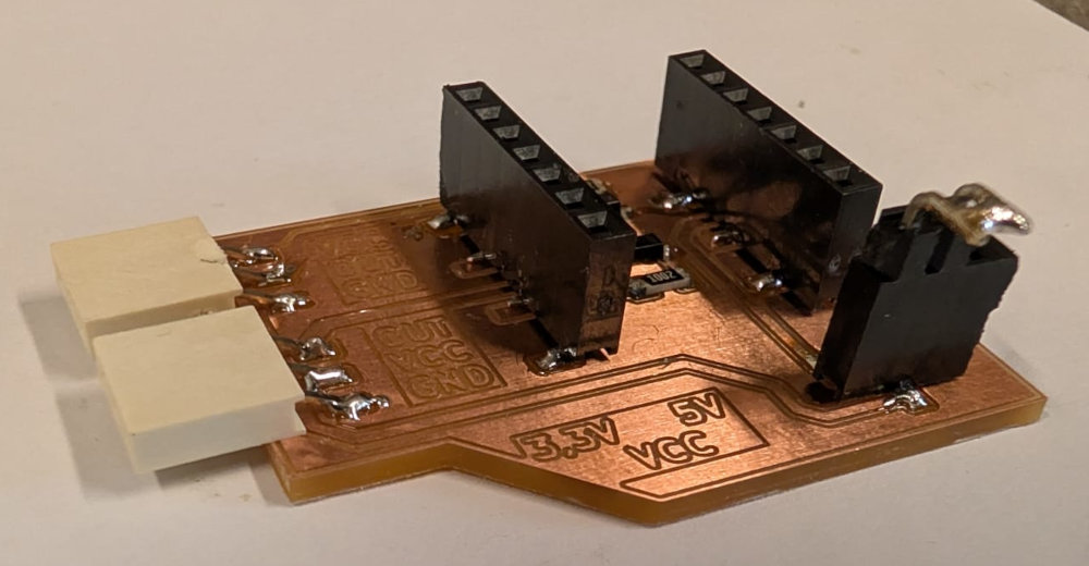
Hero shot
Making a PCB
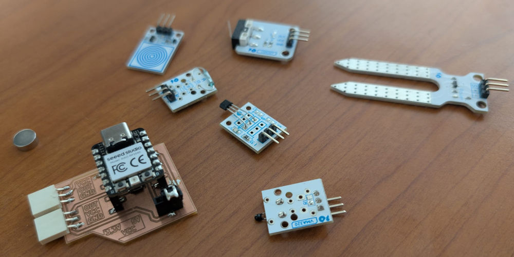
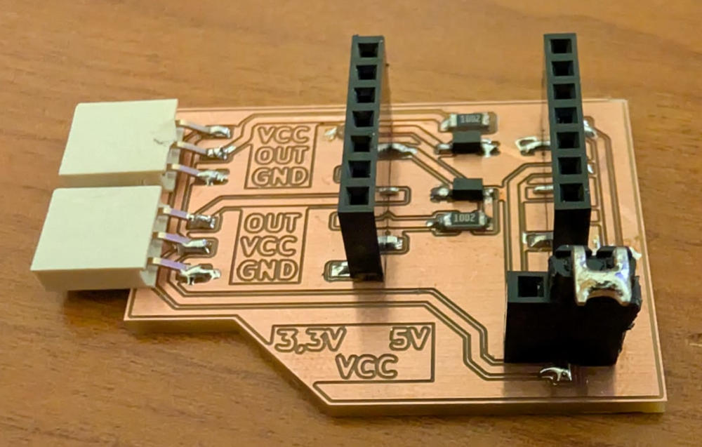
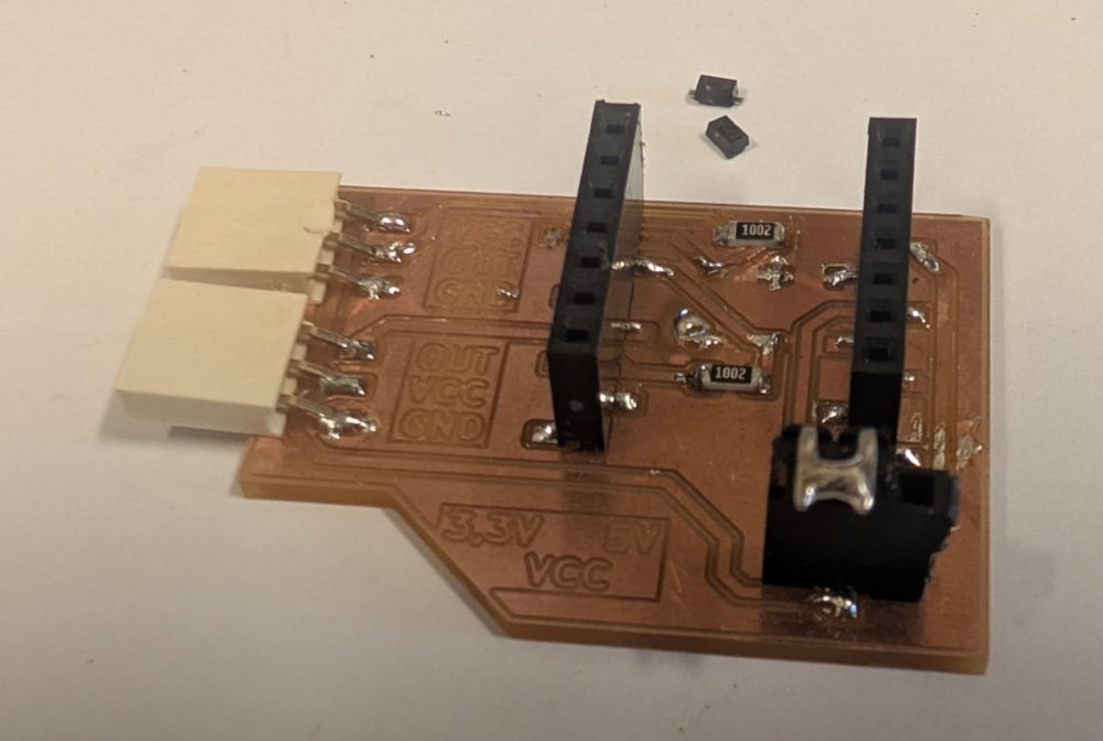
Before testing the input sensors, I'll make a PCB to test sensors that have different pinouts.
After reviewing the sensors I'll use, there were mainly 3 different pinouts (when facing them in the right position) :
- VCC OUT GND
- OUT VCC GND
- GND VCC OUT
I'll make one connector for the first one and since the last 2 are the same but reversed, I'll make a second connector for both of them, I'll just have to turn around some of the sensors (or the PCB).
I also want to add a jumper to select what supply voltage the sensor is powered with because some of them don't work well with 3,3V, so I'll need to use 5V.
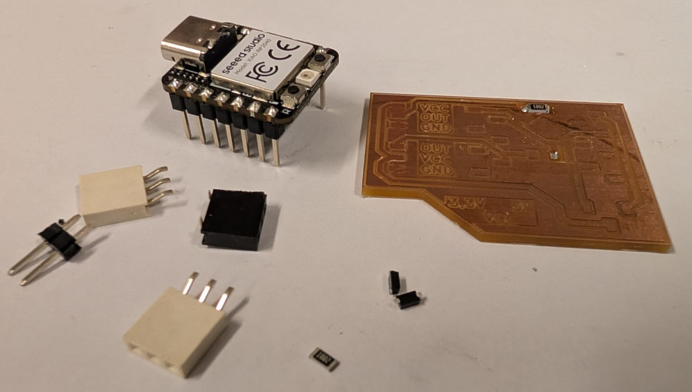
The microcontroller I'll use is a XIAO RP-2040, but it is 3,3V tolerant so I'll add a protection to limit the input voltage of the data pins.
I just redo the week 06 and week 08 assignments to draw the PCB and mill it.
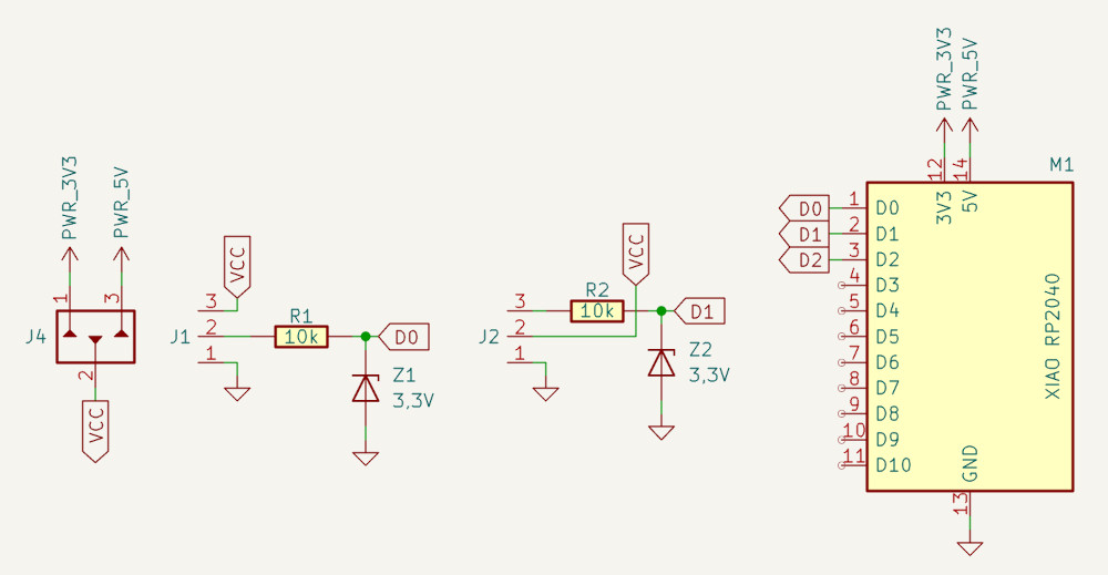
The resistor and 3,3V zener diode combo was supposed to be for the 3,3V protection but I ran into a problem I explain in the Problem(s) met section.
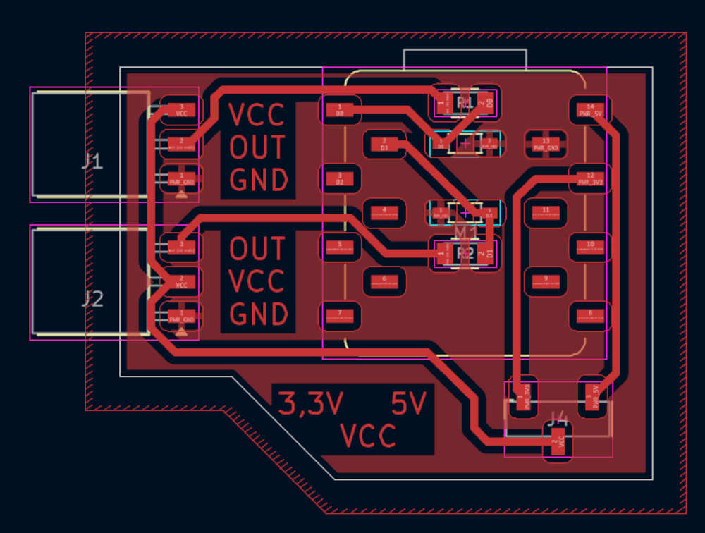
I add text to see if it comes out well and know where to connect my sensors with specific pinouts.
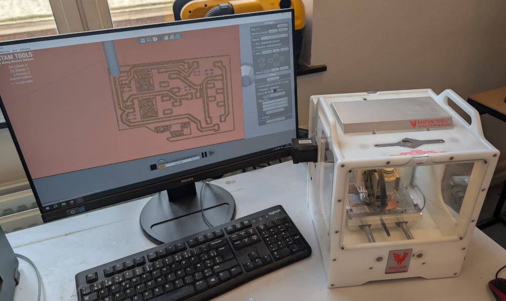
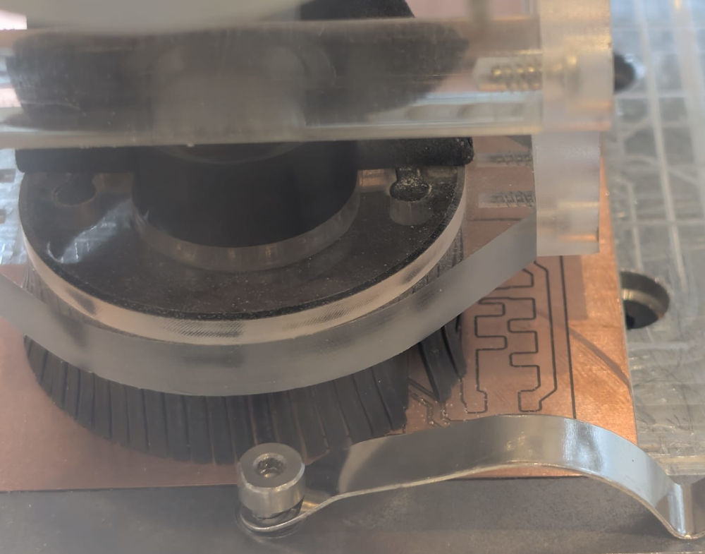
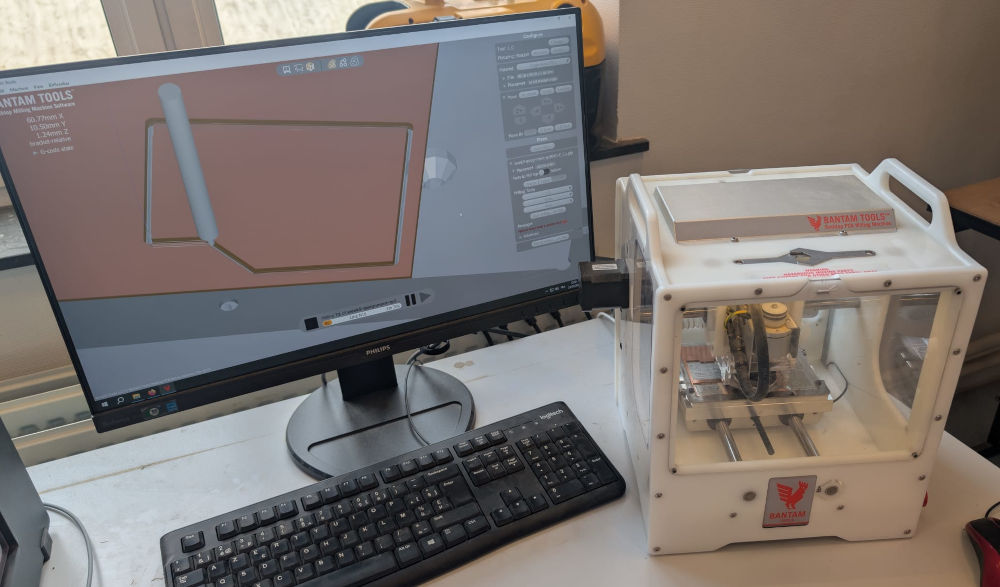
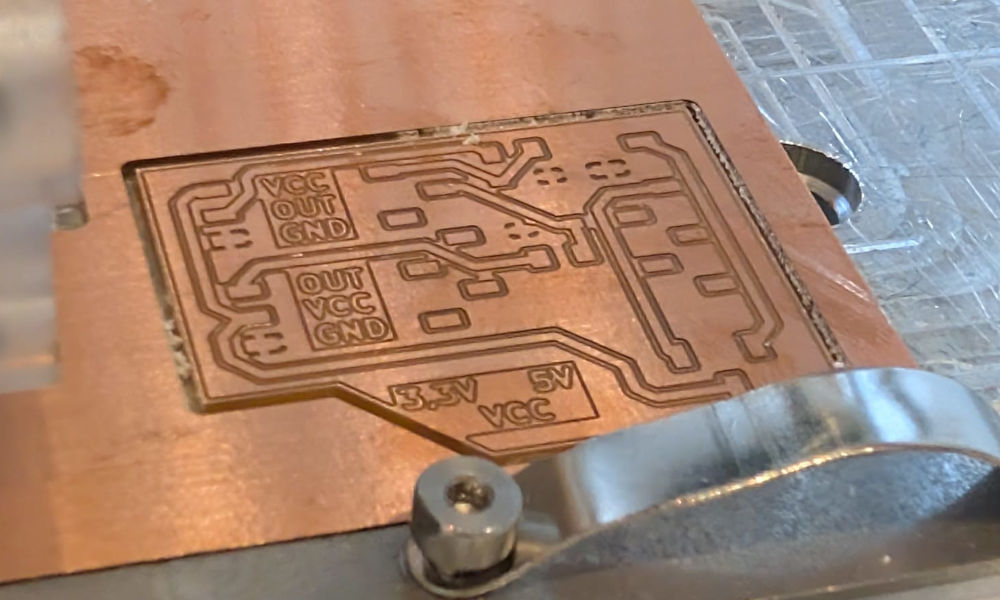
When the PCB is done, I can start using the Bantam to mill my PCB.
Like week 08, I use a 0,3mm end mill for the tracks and a 1mm end mill for the edge.
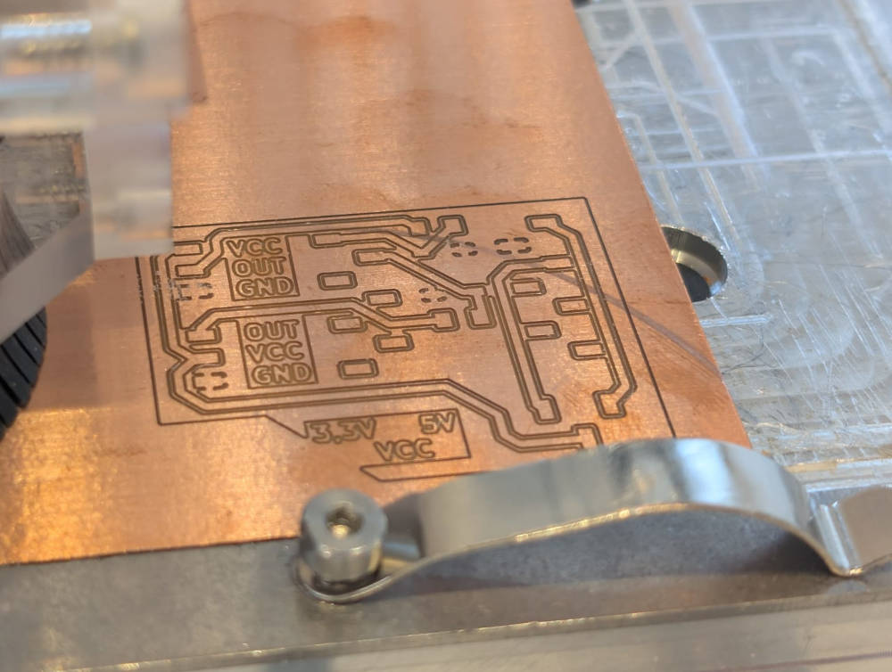
The text came out pretty well.
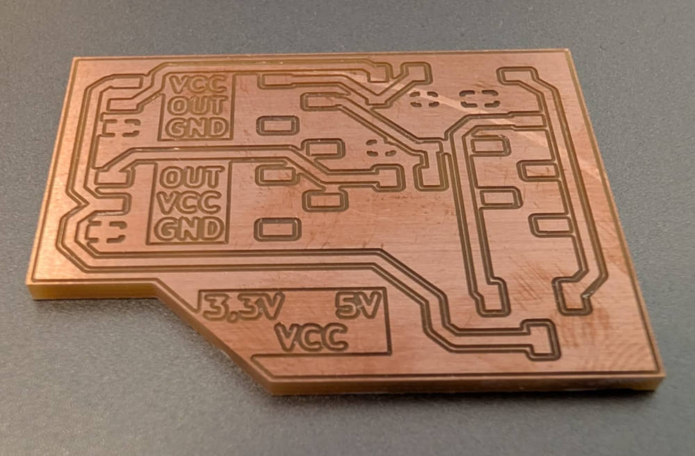
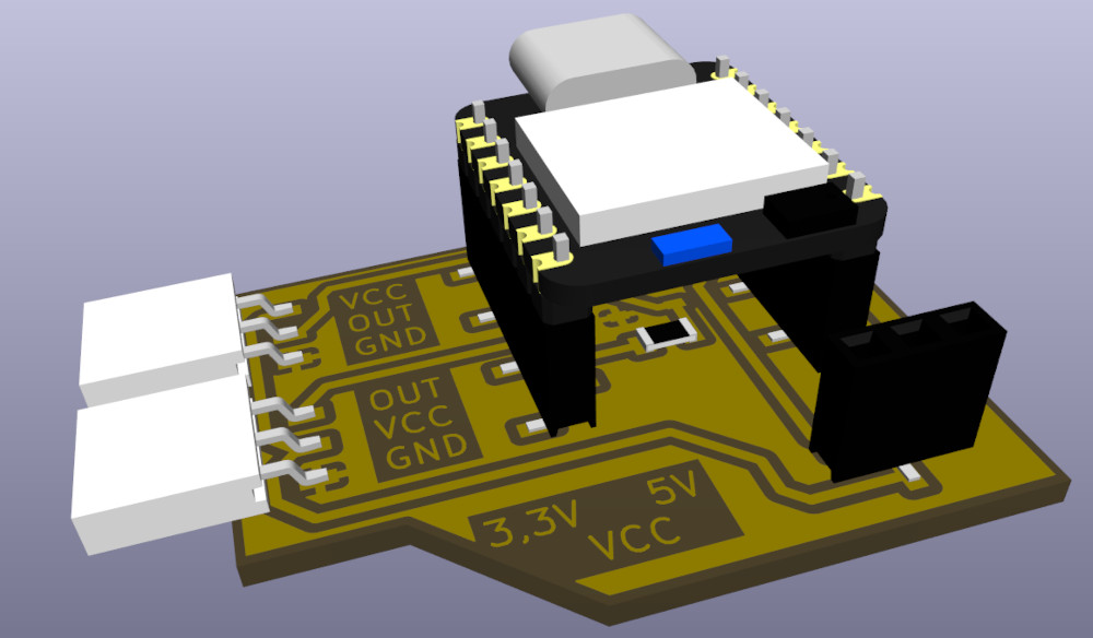
I can now solder my components.
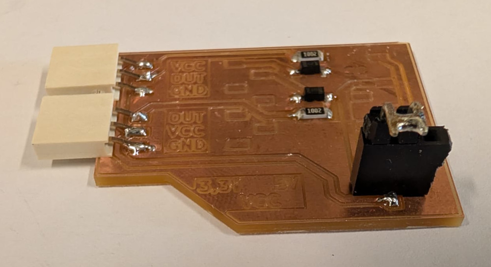
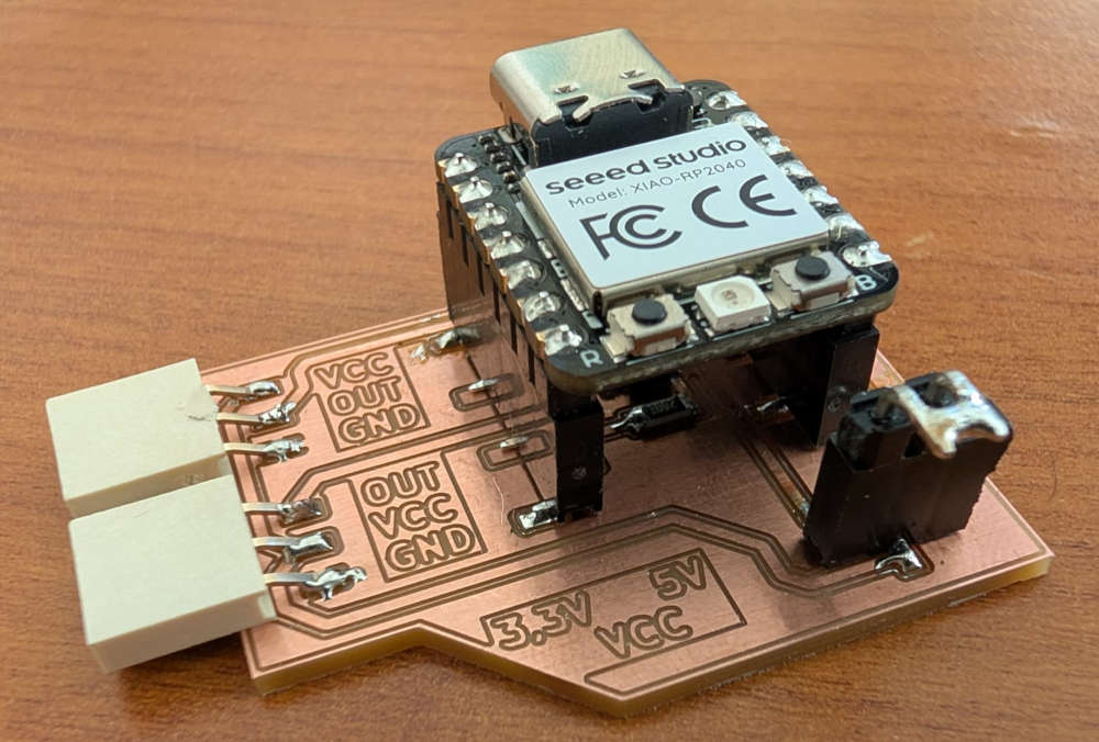
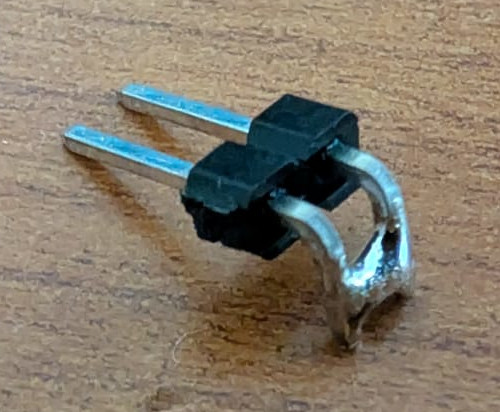
The way the jumper and VCC choice works is simple, I use a male header with 2 pins that are soldered to each other to form a connection and choose between the left for 3,3V power supply or right for 5V power supply with text indication on the left of the jumper.
For a 3,3V power supply :
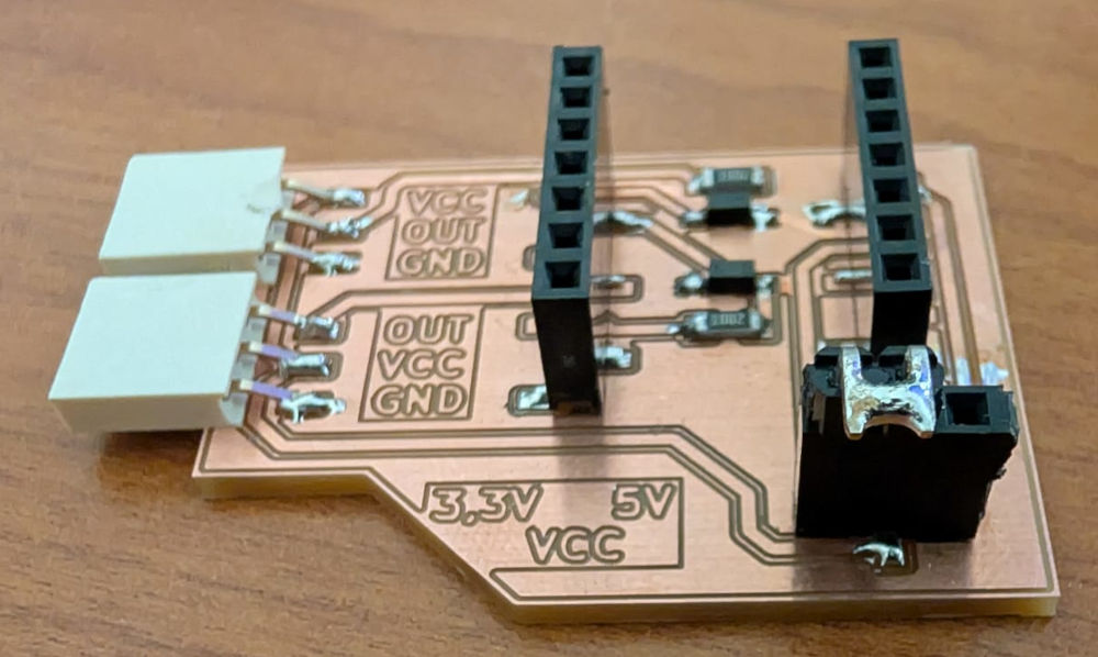
For a 5V power supply :
Now that my board is ready, I can test my sensors.
Input sensors
Our FabLab showed us the sensors they possess, they have a lot but I decided to stick to a series by Velleman that are easy and ready to use.
-
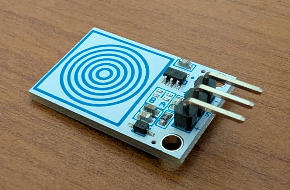
VMA305
Capacitive sensor that sends a signal when it is pressed.
                                        ###########################
                                        ### Code in MicroPython ###
                                        ###########################

                                        # VELLEMAN VMA305
                                        # Module with touch, capacitive button which requires a little pressure to activate. The output is the analog signal.

                                        from machine import Pin # For hardware functions
                                        import time # For time functions

                                        touch = Pin(26, Pin.IN, Pin.PULL_UP) # Set pin 26 as an input with internal pull-up resistor

                                        while True: # Infinite loop
                                            if touch.value() == 0: # Reads the touch's value
                                                print("Target not touched") # If the target is noy touched
                                            else:
                                                print("Target touched") # If the target is touched
                                            time.sleep(0.25) # Delay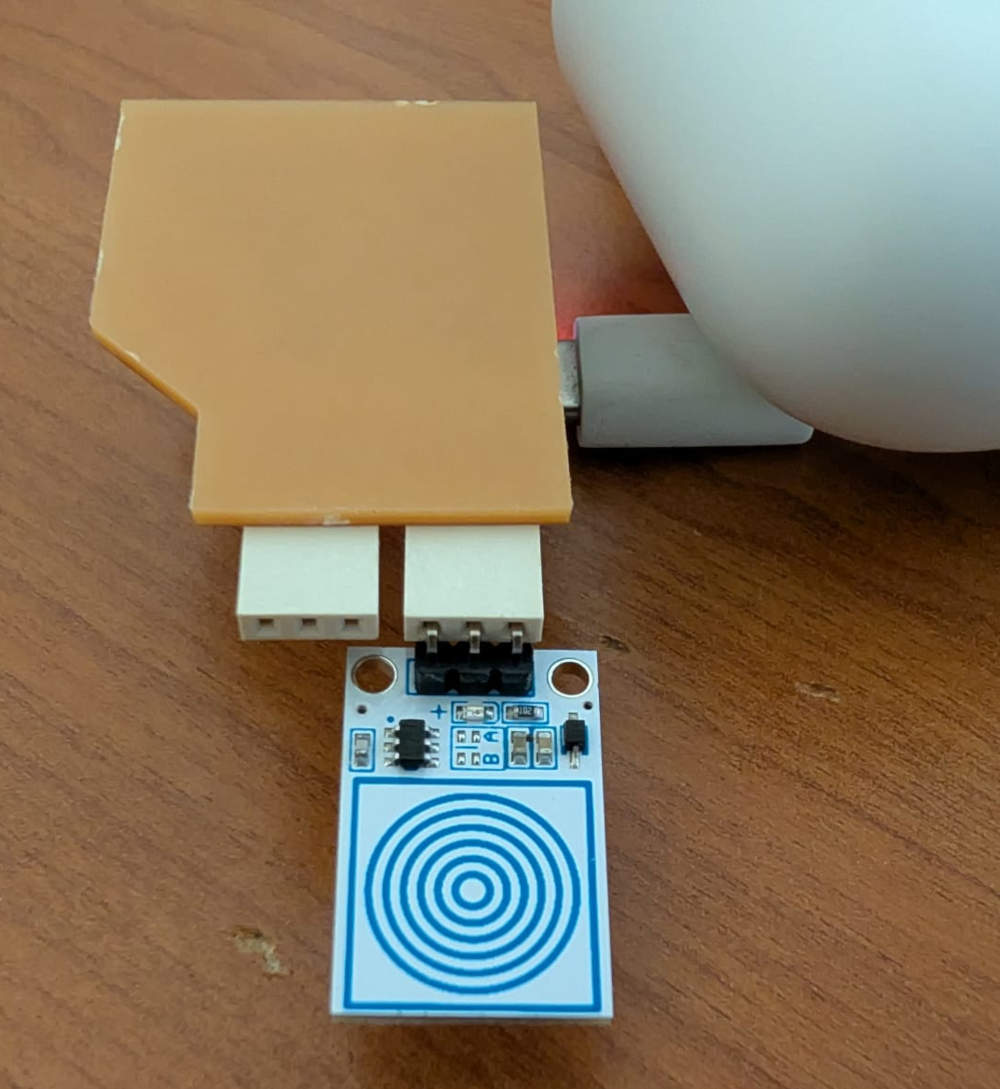
-
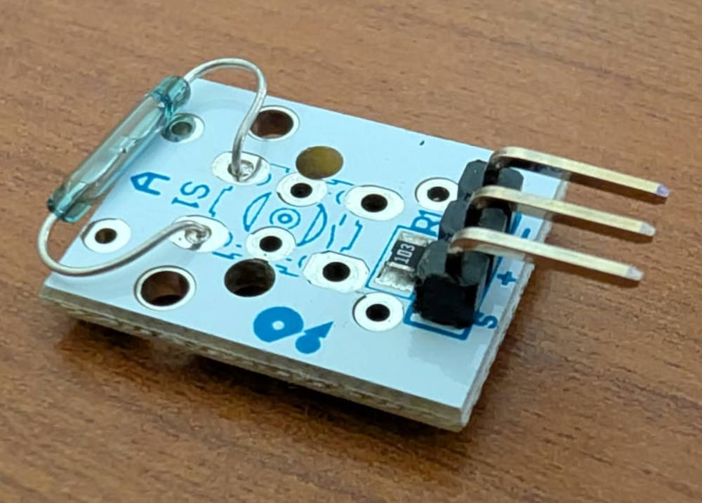
VMA308
Magnetic sensor that acts as a switch and closes when a magnetic field is detected.
                                        ###########################
                                        ### Code in MicroPython ###
                                        ###########################

                                        # VELLEMAN VMA308
                                        # A reed contact switch is a normally open contact, which closes in the presence of a magnetic field.

                                        from machine import Pin # For hardware functions
                                        import time # For time functions

                                        reed_switch = Pin(27, Pin.IN, Pin.PULL_UP) # Set pin 27 as an input with internal pull-up resistor

                                        while True: # Infinite loop
                                            if reed_switch.value() == 0: # Reads the reed switch's value
                                                print("Reed switch closed") # If the magnet is close
                                            else:
                                                print("Reed switch opened") # If the magnet is far
                                            time.sleep(0.25) # Delay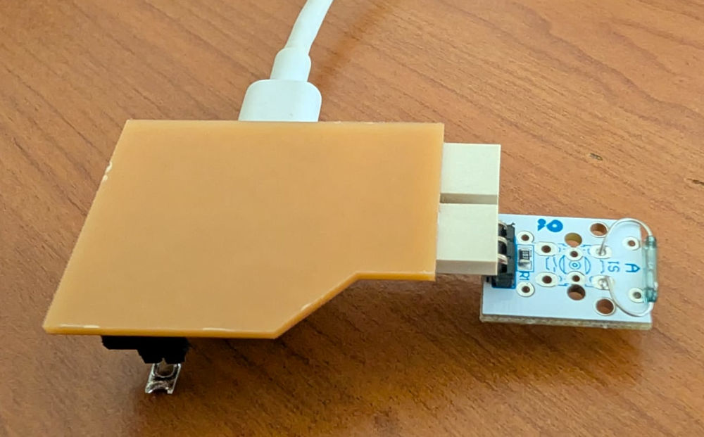
-
VMA313
Magnetic sensor that acts as a switch and toggles its value when a magnetic field is detected.
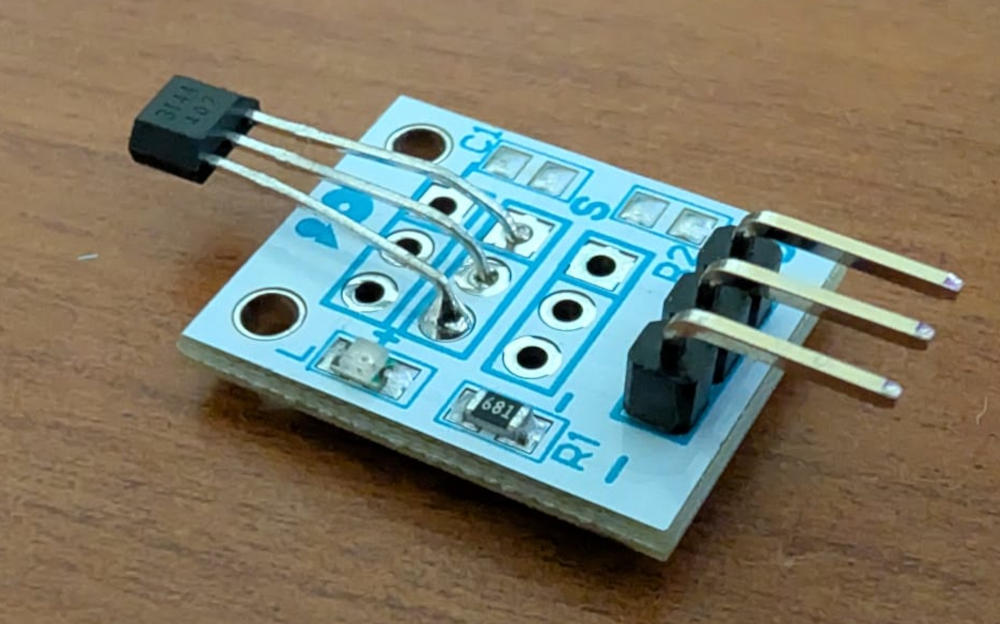
                                        ###########################
                                        ### Code in MicroPython ###
                                        ###########################

                                        # VELLEMAN VMA313
                                        # The device includes an on-chip Hall voltage generator for magnetic sensing, an amplifier that amplifies the Hall voltage,
                                        # a Schmitt trigger to provide switching hysteresis for noise rejection and an open-collector output.

                                        from machine import Pin # For hardware functions
                                        import time # For time functions

                                        hall = Pin(27, Pin.IN, Pin.PULL_UP) # Set pin 27 as an input with internal pull-up resistor

                                        while True: # Infinite loop
                                            if hall.value() == 0: # Reads the hall's value
                                                print("Magnet close") # If the magnet is close
                                            else:
                                                print("Magnet far") # If the magnet is far
                                            time.sleep(0.25) # Delay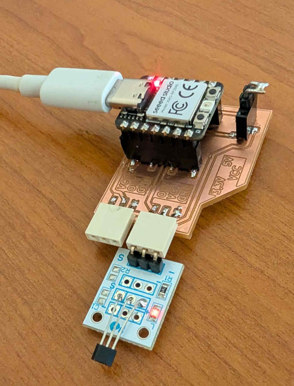
-
VMA327
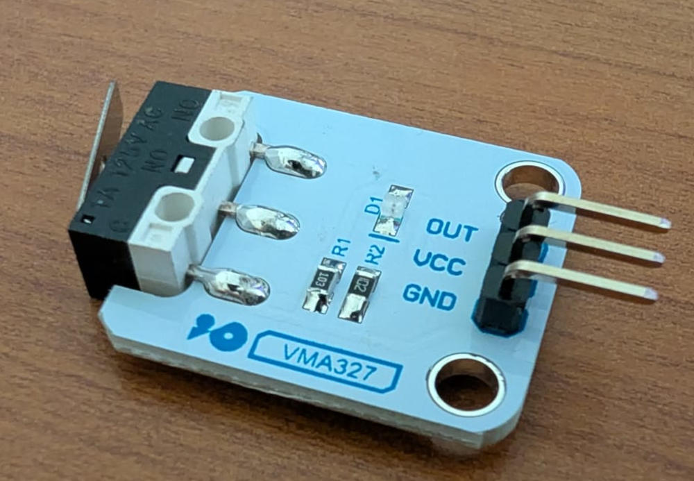
                                        ###########################
                                        ### Code in MicroPython ###
                                        ###########################

                                        # VELLEMAN VMA327
                                        # End-Stop Switch

                                        from machine import Pin # For hardware functions
                                        import time # For time functions

                                        switch = Pin(27, Pin.IN, Pin.PULL_UP) # Set pin 27 as an input with internal pull-up resistor

                                        while True: # Infinite loop
                                            if switch.value() == 0: # Reads the switch's value
                                                print("Switch pressed") # If the switch is pressed
                                            else:
                                                print("Switch released") # If the switch is released
                                            time.sleep(0.25) # Delay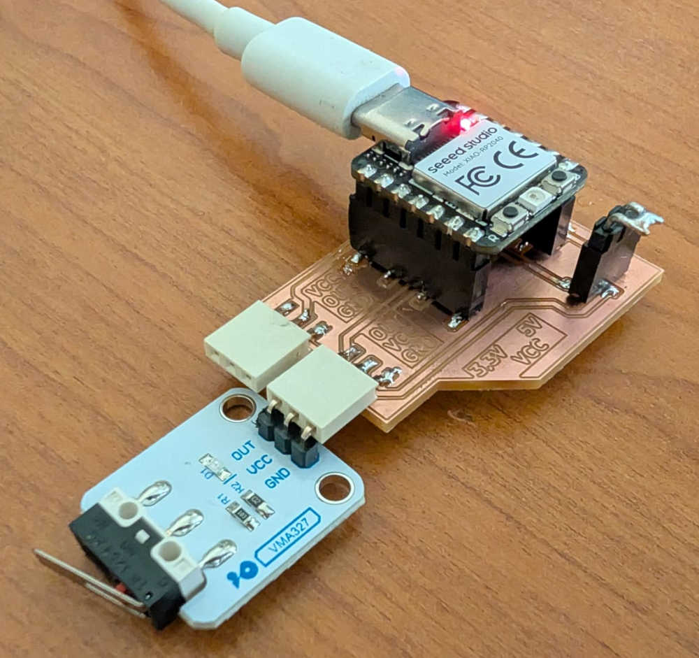
-
GP2Y0A21
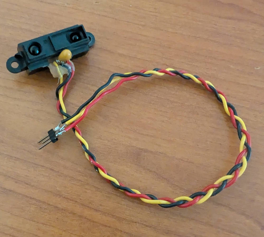
                                        ###########################
                                        ### Code in MicroPython ###
                                        ###########################

                                        # GP2Y0A21
                                        # Sharp reflective optical sensor to measure distance.

                                        from machine import ADC # For hardware functions
                                        import time # For time functions

                                        distance = ADC(26) # Initialize ADC on pin GP26 (ADC0)

                                        while True: # Infinite loop
                                            raw_value = distance.read_u16() # Reads value of ADC0 in 16 bits (0–65535)
                                            voltage = raw_value / 65535 * 3.3 # Convert to volts
                                            print("ADC raw:", raw_value, "Voltage:", round(voltage,2)) # Prints in shell
                                            time.sleep(0.25) # Delay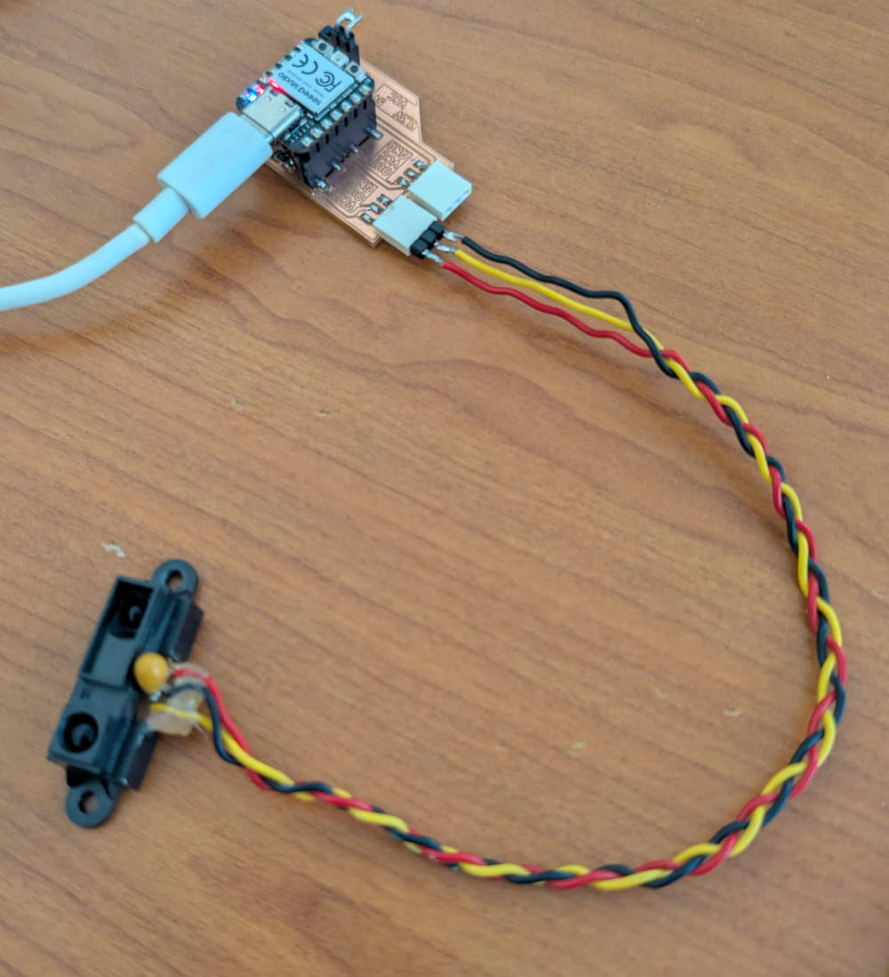
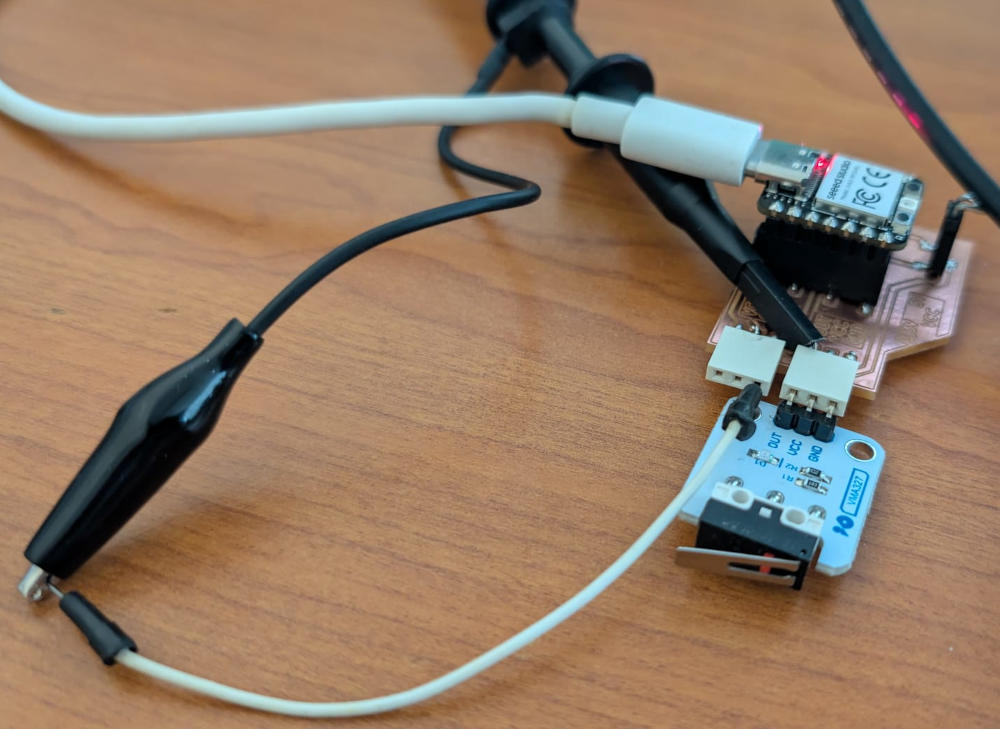
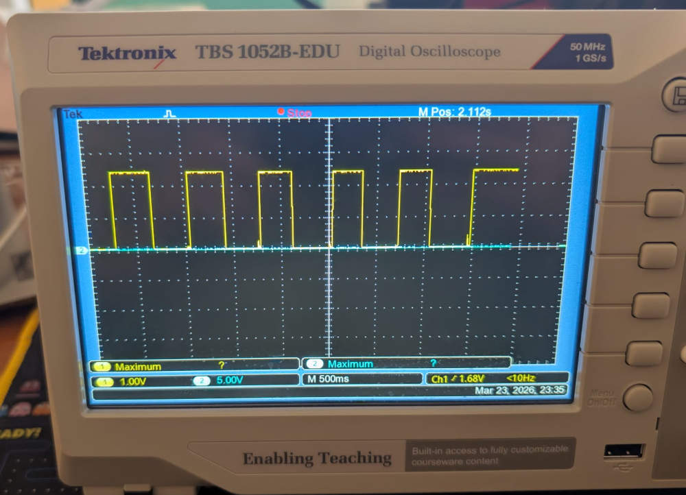
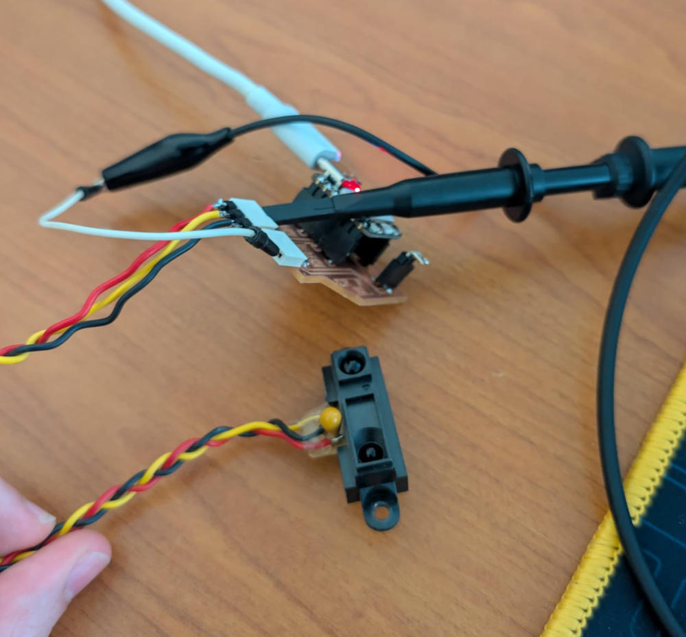
Oscilloscope
To check what the signals look like, I'll use an oscilloscope and try a digital sensor (VMA327) and an analog sensor (GP2Y0A21).
-
VMA327 - Digital sensor
Since it is a digital sensor, the value will be VCC or GND.
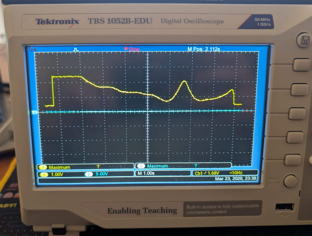
-
GP2Y0A21 - Analog sensor
Since it is an analog sensor, the value will vary between VCC and GND.
Problem(s) met
-
Voltage protection
I wanted to limit the input voltage at 3,3V in case a sensor needed to be powered with 5V but my schematic wasn't correct and the zener diode couldn't fulfill its role.
It instead worked like a divisive resistor and the max voltage I could read was half the VCC.
To fix this, I simply removed the zener diode and worked only with 3,3V sensors.
I then re-tested the analog sensor GP2Y0A21 and it worked well.
Useful file(s) (Click to download)
- VMA305 MicroPython code (Thonny)
- VMA308 MicroPython code (Thonny)
- VMA313 MicroPython code (Thonny)
- VMA327 MicroPython code (Thonny)
- GP2Y0A21 MicroPython code (Thonny)
- Week 09 PCB (KiCad)
Assignments checklist
- ✅Linked to the group assignment page.
- ✅Documented what you learned from interfacing an input device(s) to your microcontroller and optionally, how the physical property relates to the measured results.
- ✅Documented what you learned from interfacing an input device(s) to your microcontroller and optionally, how the physical property relates to the measured results.
- ✅Explained how your code works.
- ✅Explained any problems you encountered and how you fixed them.
- ✅Included original design files and source code.
- ✅Included a hero shot of your board.