Prior knowledge
|
I've mainly worked with bluetooth modules and simple to use wireless communications devices of short range in the past (433MHz transmitter and receiver module). |
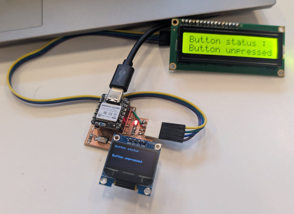
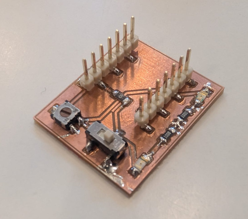
Hero shot

Wired communication
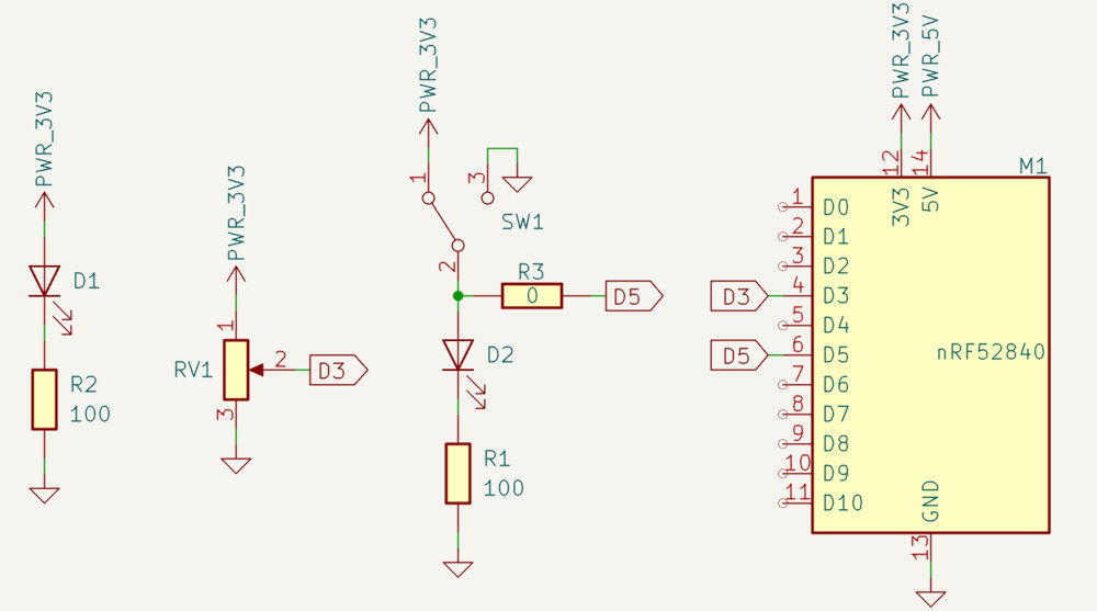
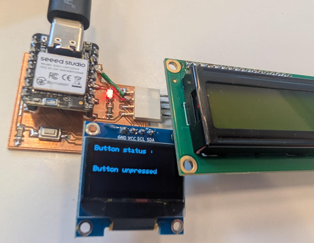
For the wired communication, I'll try a new circuit with a microcontroller I never used to communicate with a LCD and an OLED Screen (both working with I2C) the value of a button.
The microcontroller used is the SEEED XIAO-nRF52840 Sense, its pins are exactly the same as the previously used SEEED XIAO-RP2040.
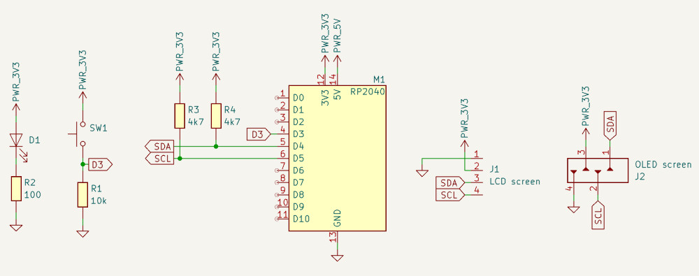
I didn't include the two 4k7 resistors for the I2C because, apparently, if the devices already have them, they are unnecessary and I didn't know if the devices already had them.
(Button mounted in pull-down)
To use this microcontroller, I had to add the packages to the Arduino IDE by adding the following line to the Preferences... : https://files.seeedstudio.com/arduino/package_seeeduino_boards_index.json.
Then, I have to add the board via the BOARDS MANAGER tab, both are fine.
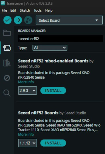
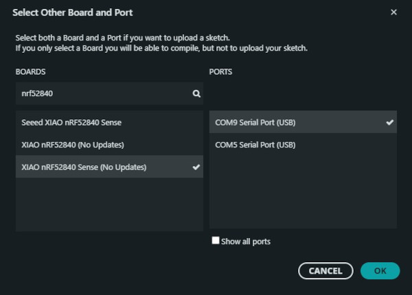
Finally, after checking online and doing different tests, the best board package to use is the mbed-enabled boards (the one with (No Updates) written next to it).
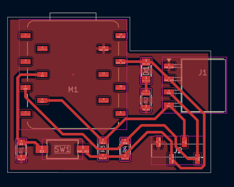
Here's the final wiring :
                            /////////////////////////////////////
                            //////////// Code in C++ ////////////
                            /////////////////////////////////////

                            #include <Wire.h>  // I2C library

                            #include <Adafruit_GFX.h>
                            #include <Adafruit_SSD1306.h>                                              // OLED library
                            #define SCREEN_WIDTH 128                                                   // OLED width in pixels
                            #define SCREEN_HEIGHT 64                                                   // OLED height in pixels
                            #define OLED_RESET -1                                                      // Not used
                            #define SCREEN_ADDRESS 0x3C                                                // OLED I2C address
                            Adafruit_SSD1306 display(SCREEN_WIDTH, SCREEN_HEIGHT, &Wire, OLED_RESET);  // Create OLED object

                            #include <hd44780.h>                        // LCD library
                            #include <hd44780ioClass/hd44780_I2Cexp.h>  // I2C expander
                            #define LCD_ADDR 0x27                       // LCD I2C address
                            hd44780_I2Cexp lcd;                         // Create LCD object

                            #define Button 3  // Button pin
                            int ButtonValue;  // Value of the button

                            void setup() {
                                Wire.begin();  // Initializes I2C

                                pinMode(Button, INPUT);  // Sets the button as an input

                                lcd.begin(16, 2);              // Initialize the LCD
                                lcd.setBacklight(HIGH);        // Turn on backlight
                                lcd.setCursor(0, 0);           // First line of the LCD
                                lcd.print("Button status :");  // Message

                                if (!display.begin(SSD1306_SWITCHCAPVCC, SCREEN_ADDRESS)) {  // Scans for the OLED adress
                                    while (1)
                                    ;
                                }
                                display.clearDisplay();               // Clears the OLED
                                display.setTextSize(1);               // Text size multiplier
                                display.setTextColor(SSD1306_WHITE);  // Color (white)
                                display.setCursor(0, 0);              // Top-left corner of the OLED
                                display.println("Button status :");   // Message
                                display.display();                    // Send buffer to OLED
                            }

                            void loop() {
                                ButtonValue = digitalRead(Button);  // Reads the value of the button

                                if (ButtonValue == 1) {                                     // If the button is pressed
                                    lcd.setCursor(0, 1);                                      // Second line of the I²C LCD screen
                                    lcd.print("Button pressed  ");                            // Message
                                    display.fillRect(0, 30, SCREEN_WIDTH, 8, SSD1306_BLACK);  // Erases a specific line
                                    display.setCursor(0, 30);                                 // Line of the OLED (X = 0, Y = 30)
                                    display.println("Button pressed");                        // Message
                                    display.display();
                                } else {                                                    // If the button is unpressed
                                    lcd.setCursor(0, 1);                                      // Second line of the I²C LCD screen
                                    lcd.print("Button unpressed");                            // Message
                                    display.fillRect(0, 30, SCREEN_WIDTH, 8, SSD1306_BLACK);  // Erases a specific line
                                    display.setCursor(0, 30);                                 // Line of the OLED (X = 0, Y = 30)
                                    display.println("Button unpressed");                      // Message
                                    display.display();                                        // Send buffer to OLED
                                }
                            }
I had to use another library for the I2C LCD screen rather than the typical one because of a warning by the Arduino IDE due to compatibility problems.
Additional libraries used can be found at the Useful file(s) section.
Used libraries :
Wireless communication
For the wireless communication, I'll use two SEEED XIAO-nRF52840 Sense to communicate between each other via BLE (Bluetooth Low Energy).
BLE is par of the Bluetooth family, it is a wireless communication technology designed for short distances (typically up to ~100 meters) while consuming minimal battery.
It works with minimum one peripheral device (transmitter) that advertises its presence and one central device (receiver) that scans and connects to the peripheral device.
It is considered low energy because it sends small packages of data instead of continuous data and letting the device stay in sleep mode to save power consumption.
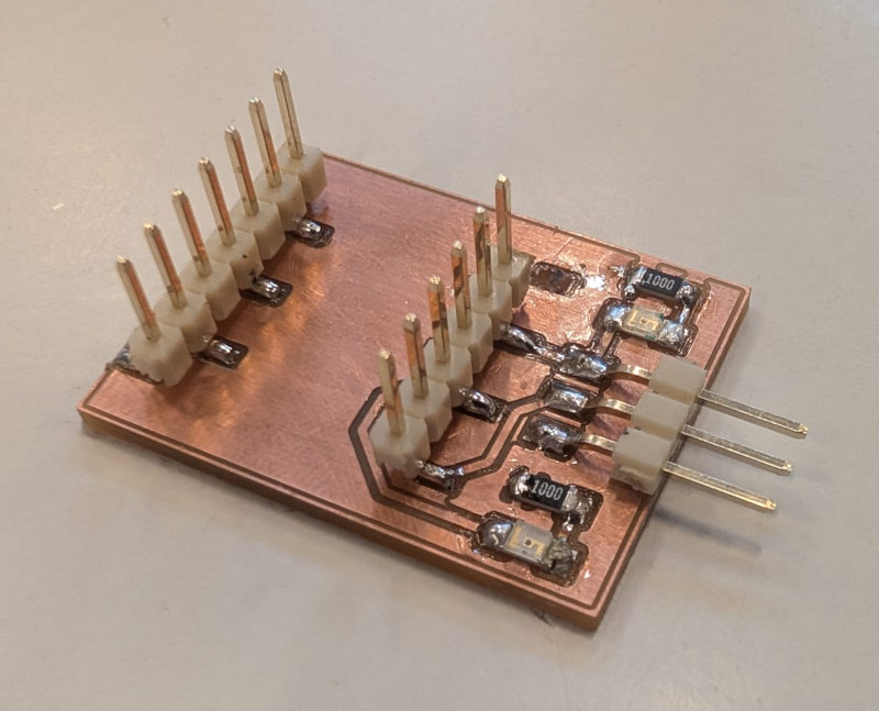
There are 2 PCBs, the first one for the inputs, with a potentiometer and a button and the second one for the outputs, with a servomotor and a LED.
The button will turn on or off the LED and the potentiometer will control the position of the servomotor.
-
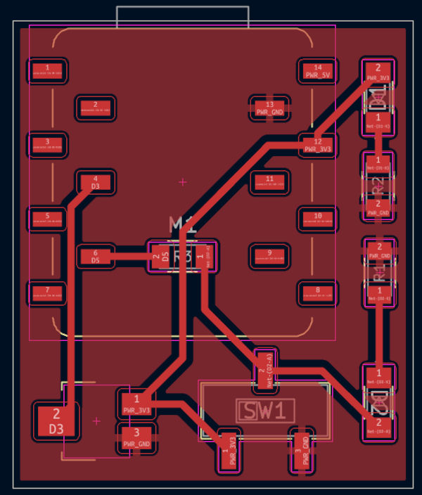
Wireless input PCB
-
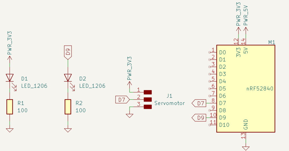
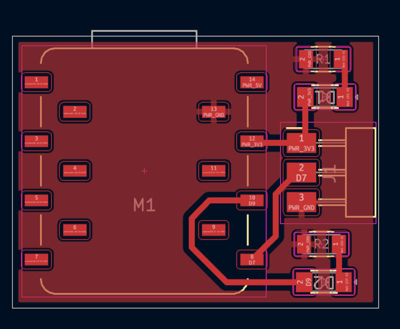
Wireless output PCB
-
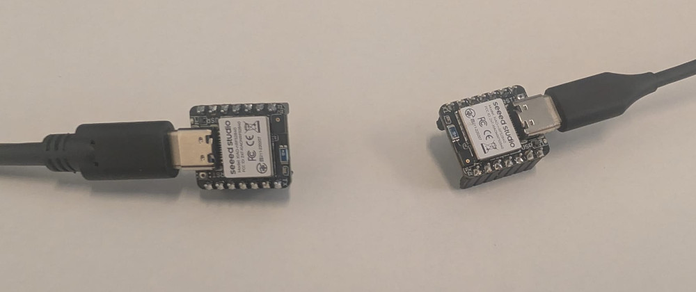
Communication test
Simple communication test using BLE between 2 XIAO-nRF52840 to send some text, the left one is the peripheral and the right one is the central.
To use BLE, I have to download the library ArduinoBLE.
Peripheral code :
                                        // Library for Bluetooth Low Energy
                                        #include <ArduinoBLE.h>

                                        // Define BLE service
                                        BLEService messageService("180C");
                                        /*
                                        "180C" : Custom service UUID ("Universally Unique Identifier")
                                        */

                                        // Define BLE characteristic
                                        BLEStringCharacteristic messageChar("2A56", BLERead | BLENotify, 50);
                                        /*
                                        "2A56" : Standard characteristic UUID
                                        BLERead | BLENotify : Properties of the characteristic :
                                                                - BLERead = central can read the value
                                                                - BLENotify = peripheral can notify the central when the value changes
                                        50 : Maximum length of the string in bytes
                                        */

                                        void setup() {
                                            // Initialization of the serial communication
                                            Serial.begin(115200);
                                            while (!Serial)
                                                ;

                                            //Initialization of the BLE
                                            if (!BLE.begin()) {
                                                Serial.println("BLE failed to start !");
                                                while (1)
                                                ;
                                            }

                                            // Set peripheral device name
                                            BLE.setLocalName("XIAO_BLE");
                                            // Advertise a service
                                            BLE.setAdvertisedService(messageService);
                                            // Add characteristic to service
                                            messageService.addCharacteristic(messageChar);
                                            // Add service to BLE stack
                                            BLE.addService(messageService);
                                            // Set initial value
                                            messageChar.writeValue("Hello from XIAO!");
                                            // Start advertising
                                            BLE.advertise();
                                            // Prints to the Serial Monitor
                                            Serial.println("BLE device is now advertising...");
                                        }

                                        void loop() {
                                            // Detects a central device
                                            BLEDevice central = BLE.central();

                                            // If a central device is detected
                                            if (central) {
                                                Serial.print("Connected to central: ");
                                                // Prints the MAC address of the central device
                                                Serial.println(central.address());

                                                // Makes sure the central device is still connected
                                                while (central.connected()) {
                                                    // Send updated message every 2 seconds
                                                    messageChar.writeValue("Hello BLE!");
                                                    delay(2000);
                                                }
                                                Serial.println("Disconnected");
                                            }
                                        }
Central code :
// Library for Bluetooth Low Energy #include <ArduinoBLE.h> // Name of the peripheral device const char* deviceName = "XIAO_BLE"; // Define BLE UUID, must match with the peripheral BLEUuid serviceUUID("180C"); void setup() { // Initialization of the serial communication Serial.begin(115200); while (!Serial) ; //Initialization of the BLE if (!BLE.begin()) { Serial.println("BLE failed to start !"); while (1) ; } // Scans for nearby BLE peripheral devices BLE.scan(); // Prints to the Serial Monitor Serial.println("Scanning for BLE device..."); } void loop() { // Detects a peripheral device BLEDevice peripheral = BLE.available(); // If a peripheral device is detected if (peripheral) { // Checks the peripheral device's name if (peripheral.localName() == deviceName) { Serial.println("Found XIAO device!"); //Stops the scan BLE.stopScan(); // if (connectToPeripheral(peripheral)) { Serial.println("Done reading."); } // Restart scanning after disconnect BLE.scan(); } } } // Function to connect to a BLE peripheral, read a characteristic, and handle disconnection. bool connectToPeripheral(BLEDevice peripheral) { Serial.print("Connecting to: "); // Prints the MAC address of the peripheral device Serial.println(peripheral.address()); // Connects to the peripheral device if (!peripheral.connect()) { Serial.println("Connection failed!"); return false; } Serial.println("Connected!"); // Scans the peripheral device to find all services and characteristics if (!peripheral.discoverAttributes()) { Serial.println("Attribute discovery failed!"); peripheral.disconnect(); return false; } // Searches for the characteristic with UUID "2A56" of the peripheral BLECharacteristic messageChar = peripheral.characteristic("2A56"); // Must match the peripheral device's characteristic UUID if (!messageChar) { Serial.println("Characteristic not found!"); peripheral.disconnect(); return false; } // Ensures that this characteristic supports reading if (!messageChar.canRead()) { Serial.println("Cannot read characteristic!"); peripheral.disconnect(); return false; } // Read the characteristic repeatedly while (peripheral.connected()) { BLECharacteristic messageChar = peripheral.characteristic("2A56"); if (messageChar && messageChar.canRead()) { // Reads the value of the characteristic into a buffer of 50 bytes char buffer[50]; // Stores how many bytes were read int len = messageChar.readValue((unsigned char*)buffer, sizeof(buffer)); // Ensures the value is converted into a proper C-string if (len > 0 && len < sizeof(buffer)) { buffer[len] = '\0'; Serial.print("Received: "); Serial.println(buffer); } } delay(2000); } Serial.println("Disconnected."); // Returns true to indicate successful reading and disconnection return true; } -
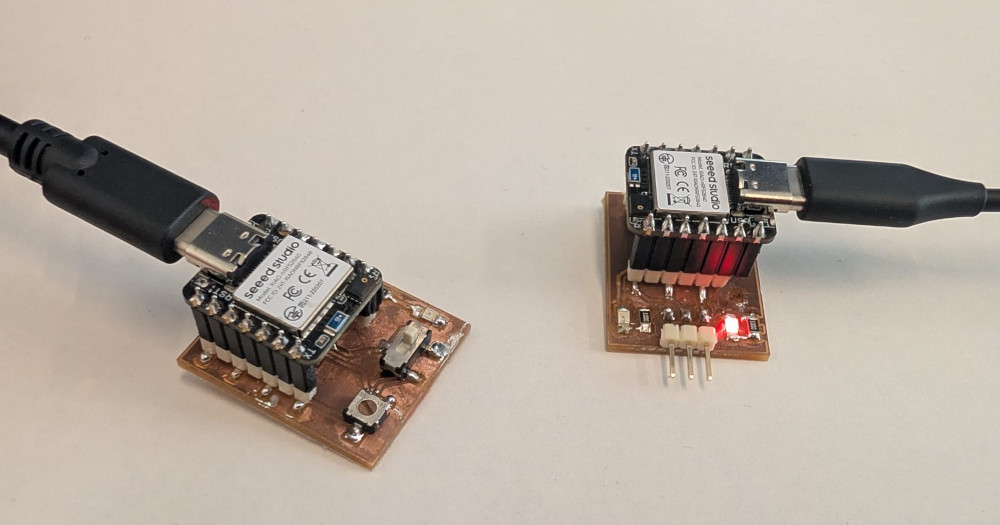
Button and LED test
Control the status of a LED depending of the value of a button wirelessly.
Here's the final wiring :
Peripheral code :
                                        // Library for Bluetooth Low Energy
                                        #include <ArduinoBLE.h>

                                        // Define BLE service
                                        BLEService messageService("180C");
                                        /*
                                        "180C" : Custom service UUID ("Universally Unique Identifier")
                                        */

                                        // Define BLE characteristic
                                        BLEStringCharacteristic messageChar("2A56", BLERead | BLENotify, 50);
                                        /*
                                        "2A56" : Standard characteristic UUID
                                        BLERead | BLENotify : Properties of the characteristic :
                                                                - BLERead = central can read the value
                                                                - BLENotify = peripheral can notify the central when the value changes
                                        50 : Maximum length of the string in bytes
                                        */

                                        // Button pin
                                        #define button 5
                                        // Variable to stock the button value
                                        int buttonValue;

                                        void setup() {
                                            // Sets the button as an input
                                            pinMode(button, INPUT);

                                            // Initialization of the serial communication
                                            Serial.begin(115200);
                                            while (!Serial)
                                                ;

                                            //Initialization of the BLE
                                            if (!BLE.begin()) {
                                                Serial.println("BLE failed to start !");
                                                while (1)
                                                ;
                                            }

                                            // Set peripheral device name
                                            BLE.setLocalName("XIAO_BLE");
                                            // Advertise a service
                                            BLE.setAdvertisedService(messageService);
                                            // Add characteristic to service
                                            messageService.addCharacteristic(messageChar);
                                            // Add service to BLE stack
                                            BLE.addService(messageService);
                                            // Set initial value
                                            messageChar.writeValue("Hello from XIAO!");
                                            // Start advertising
                                            BLE.advertise();
                                            // Prints to the Serial Monitor
                                            Serial.println("BLE device is now advertising...");
                                        }

                                        void loop() {
                                            // Detects a central device
                                            BLEDevice central = BLE.central();

                                            // If a central device is detected
                                            if (central) {
                                                Serial.print("Connected to central: ");
                                                // Prints the MAC address of the central device
                                                Serial.println(central.address());

                                                // Makes sure the central device is still connected
                                                while (central.connected()) {
                                                    // Reads the value of the button
                                                    buttonValue = digitalRead(button);

                                                    // If the button is pressed
                                                    if (buttonValue == 1) {
                                                        messageChar.writeValue("Button ON");
                                                        Serial.println("Button ON");
                                                    }
                                                    // If the button is not pressed
                                                    else {
                                                        messageChar.writeValue("Button OFF");
                                                        Serial.println("Button OFF");
                                                    }
                                                    // Send updated message every 50 milliseconds
                                                    delay(50);
                                                }
                                                Serial.println("Disconnected");
                                            }
                                        }
Central code :
Added a library to control and compare the text received more easily.
// Library for Bluetooth Low Energy #include <ArduinoBLE.h> // Library for C-style strings #include <cstring> // Name of the peripheral device const char* deviceName = "XIAO_BLE"; // Define BLE UUID, must match with the peripheral BLEUuid serviceUUID("180C"); // LED pin #define LED 9 void setup() { // Sets the LED as an output pinMode(LED, OUTPUT); // Initialization of the serial communication Serial.begin(115200); while (!Serial) ; //Initialization of the BLE if (!BLE.begin()) { Serial.println("BLE failed to start !"); while (1) ; } // Scans for nearby BLE peripheral devices BLE.scan(); // Prints to the Serial Monitor Serial.println("Scanning for BLE device..."); } void loop() { // Detects a peripheral device BLEDevice peripheral = BLE.available(); // If a peripheral device is detected if (peripheral) { // Checks the peripheral device's name if (peripheral.localName() == deviceName) { Serial.println("Found XIAO device!"); //Stops the scan BLE.stopScan(); // if (connectToPeripheral(peripheral)) { Serial.println("Done reading."); } // Restart scanning after disconnect BLE.scan(); } } } // Function to connect to a BLE peripheral, read a characteristic, and handle disconnection. bool connectToPeripheral(BLEDevice peripheral) { Serial.print("Connecting to: "); // Prints the MAC address of the peripheral device Serial.println(peripheral.address()); // Connects to the peripheral device if (!peripheral.connect()) { Serial.println("Connection failed!"); return false; } Serial.println("Connected!"); // Scans the peripheral device to find all services and characteristics if (!peripheral.discoverAttributes()) { Serial.println("Attribute discovery failed!"); peripheral.disconnect(); return false; } // Searches for the characteristic with UUID "2A56" of the peripheral BLECharacteristic messageChar = peripheral.characteristic("2A56"); // Must match the peripheral device's characteristic UUID if (!messageChar) { Serial.println("Characteristic not found!"); peripheral.disconnect(); return false; } // Ensures that this characteristic supports reading if (!messageChar.canRead()) { Serial.println("Cannot read characteristic!"); peripheral.disconnect(); return false; } // Read the characteristic repeatedly while (peripheral.connected()) { BLECharacteristic messageChar = peripheral.characteristic("2A56"); if (messageChar && messageChar.canRead()) { // Reads the value of the characteristic into a buffer of 50 bytes char buffer[50]; // Stores how many bytes were read int len = messageChar.readValue((unsigned char*)buffer, sizeof(buffer)); // Ensures the value is converted into a proper C-string if (len > 0 && len < sizeof(buffer)) { buffer[len] = '\0'; Serial.print("Received: "); Serial.println(buffer); // If the button is pressed if (strcmp(buffer, "Button ON") == 0) { digitalWrite(LED, HIGH); } // If the button is not pressed else { digitalWrite(LED, LOW); } } } delay(50); } Serial.println("Disconnected."); // Returns true to indicate successful reading and disconnection return true; } -
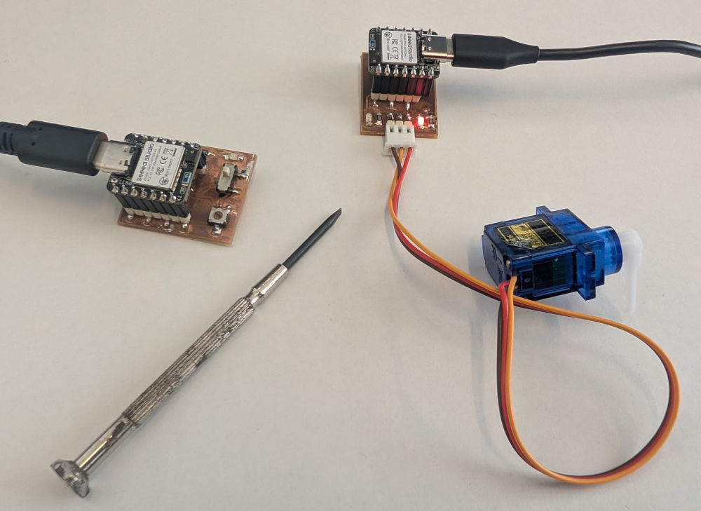
Potentiometer and servomotor test
Control the position of a servomotor depending of the value of a potentiometer wirelessly.
Here's the final wiring :
Peripheral code :
                                        // Library for Bluetooth Low Energy
                                        #include <ArduinoBLE.h>

                                        // Define BLE service
                                        BLEService messageService("180C");
                                        /*
                                        "180C" : Custom service UUID ("Universally Unique Identifier")
                                        */

                                        // Define BLE characteristic
                                        BLEStringCharacteristic messageChar("2A56", BLERead | BLENotify, 50);
                                        /*
                                        "2A56" : Standard characteristic UUID
                                        BLERead | BLENotify : Properties of the characteristic :
                                                                - BLERead = central can read the value
                                                                - BLENotify = peripheral can notify the central when the value changes
                                        50 : Maximum length of the string in bytes
                                        */

                                        // Potentiometer pin
                                        #define potentiometer 3
                                        // Variable to stock the potentiometer value
                                        int potentiometerValue;

                                        void setup() {
                                            // Sets the button as an input
                                            pinMode(potentiometer, INPUT);

                                            // Initialization of the serial communication
                                            Serial.begin(115200);
                                            while (!Serial)
                                                ;

                                            //Initialization of the BLE
                                            if (!BLE.begin()) {
                                                Serial.println("BLE failed to start !");
                                                while (1)
                                                ;
                                            }

                                            // Set peripheral device name
                                            BLE.setLocalName("XIAO_BLE");
                                            // Advertise a service
                                            BLE.setAdvertisedService(messageService);
                                            // Add characteristic to service
                                            messageService.addCharacteristic(messageChar);
                                            // Add service to BLE stack
                                            BLE.addService(messageService);
                                            // Set initial value
                                            messageChar.writeValue("Hello from XIAO!");
                                            // Start advertising
                                            BLE.advertise();
                                            // Prints to the Serial Monitor
                                            Serial.println("BLE device is now advertising...");
                                        }

                                        void loop() {
                                            // Detects a central device
                                            BLEDevice central = BLE.central();

                                            // If a central device is detected
                                            if (central) {
                                                Serial.print("Connected to central: ");
                                                // Prints the MAC address of the central device
                                                Serial.println(central.address());

                                                // Makes sure the central device is still connected
                                                while (central.connected()) {
                                                    // Reads the value of the button
                                                    potentiometerValue = analogRead(potentiometer);

                                                    // Converts and sends the value
                                                    String value = String(potentiometerValue);
                                                    messageChar.writeValue(value);
                                                    Serial.println(potentiometerValue);

                                                    // Send updated message every 50 milliseconds
                                                    delay(50);
                                                }
                                                Serial.println("Disconnected");
                                            }
                                        }
Central code :
Added a library to control the servomotor.
// Library for Bluetooth Low Energy #include <ArduinoBLE.h> // Library for C-style strings #include <cstring> // Library for servomotor #include <Servo.h> // Name of the peripheral device const char* deviceName = "XIAO_BLE"; // Define BLE UUID, must match with the peripheral BLEUuid serviceUUID("180C"); // Servomotor pin #define servomotor D7 // Creation of a servo object Servo myServo; // Value of the position of servomotor from 0 to 1023 int servoValue; // Value of the position of servomotor from 0° to 180° int servoPosition; void setup() { // Attach servo to pin D7 myServo.attach(servomotor); // Initialization of the serial communication Serial.begin(115200); while (!Serial) ; //Initialization of the BLE if (!BLE.begin()) { Serial.println("BLE failed to start !"); while (1) ; } // Scans for nearby BLE peripheral devices BLE.scan(); // Prints to the Serial Monitor Serial.println("Scanning for BLE device..."); } void loop() { // Detects a peripheral device BLEDevice peripheral = BLE.available(); // If a peripheral device is detected if (peripheral) { // Checks the peripheral device's name if (peripheral.localName() == deviceName) { Serial.println("Found XIAO device!"); //Stops the scan BLE.stopScan(); if (connectToPeripheral(peripheral)) { Serial.println("Done reading."); } // Restart scanning after disconnect BLE.scan(); } } } // Function to connect to a BLE peripheral, read a characteristic, and handle disconnection. bool connectToPeripheral(BLEDevice peripheral) { Serial.print("Connecting to: "); // Prints the MAC address of the peripheral device Serial.println(peripheral.address()); // Connects to the peripheral device if (!peripheral.connect()) { Serial.println("Connection failed!"); return false; } Serial.println("Connected!"); // Scans the peripheral device to find all services and characteristics if (!peripheral.discoverAttributes()) { Serial.println("Attribute discovery failed!"); peripheral.disconnect(); return false; } // Searches for the characteristic with UUID "2A56" of the peripheral BLECharacteristic messageChar = peripheral.characteristic("2A56"); // Must match the peripheral device's characteristic UUID if (!messageChar) { Serial.println("Characteristic not found!"); peripheral.disconnect(); return false; } // Ensures that this characteristic supports reading if (!messageChar.canRead()) { Serial.println("Cannot read characteristic!"); peripheral.disconnect(); return false; } // Read the characteristic repeatedly while (peripheral.connected()) { BLECharacteristic messageChar = peripheral.characteristic("2A56"); if (messageChar && messageChar.canRead()) { // Reads the value of the characteristic into a buffer of 50 bytes char buffer[50]; // Stores how many bytes were read int len = messageChar.readValue((unsigned char*)buffer, sizeof(buffer)); // Ensures the value is converted into a proper C-string if (len > 0 && len < sizeof(buffer)) { buffer[len] = '\0'; servoValue = atoi(buffer); Serial.print("Received (string): "); Serial.println(buffer); Serial.print("Converted to int: "); Serial.println(servoValue); // Calculation of the position of the servomotor (5.69 -> 1023/180°) servoPosition = (float)servoValue / 5.69; // Position of the servomotor (0° to 180°) myServo.write(servoPosition); } } delay(50); } Serial.println("Disconnected."); // Returns true to indicate successful reading and disconnection return true; }
Used libraries :
Problem(s) met
-
LCD screen power supply
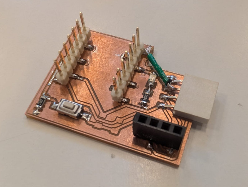
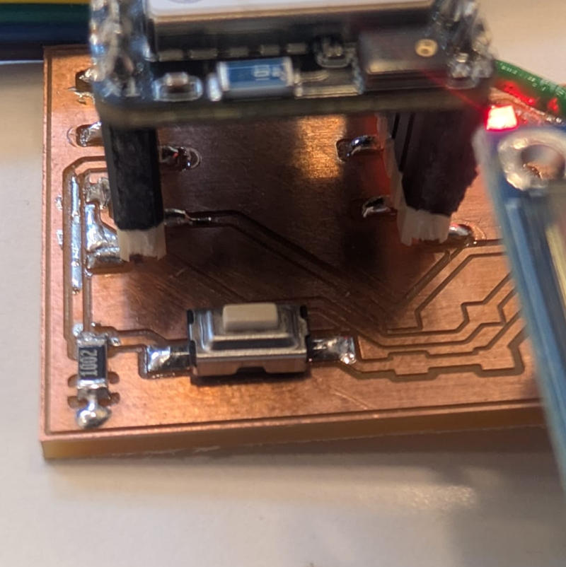
At first, the LCD screen was powered with 3,3V but the display wasn't bright enough so I changed to a 5V power supply with a cable (green cable) and the result was much better.
-
Screens connectors not well placed
When making the PCB, I tried to space out the 2 connectors of the screens so they wont touch each other but I didn't give them enough space and if I try to put both screens on their connectors, they overlap so I had to use cables for the LCD screen.
-
Board package
During my initial tests, I used the non mbed-enabled board and had a lot of conflict or missing basic libraries that led to multiple problems and try different codes or add libraries but after trying the mbed board, they were no more problems and everything worked fine.
Useful file(s) (Click to download)
- Wired PCB (KiCad)
- Libraries for screens (Arduino IDE)
- Code for screens (Arduino IDE)
- Wireless inputs PCB (KiCad)
- Wired outputs PCB (KiCad)
- Libraries for wireless codes (Arduino IDE)
- Code for simple communication (Arduino IDE)
- Code for button and LED wireless control (Arduino IDE)
- Code for potentiometer and servomotor wireless control (Arduino IDE)
Assignments checklist
- ✅Linked to the group assignment page.
- ✅Documented your project and what you have learned from implementing networking and/or communication protocols.
- ✅Explained the programming process(es) you used.
- ✅Ensured and documented that your addressing for boards works.
- ✅Outlined problems and how you fixed them.
- ✅Included design files (or linked to where they are located if you are using a board you have designed and fabricated earlier) and original source code.
- ✅Included a hero shot of your network and/or communications setup.