Week 07 — Computer-Controlled Machining
Group assignment
Individual assignment
Learning outcomes
Checklist
- Linked to the group assignment page
- Reflected on your individual page what you learned of your labs safety training
- Documented how you designed your object and made your CAM-toolpath
- Documented how you milled and assembled your final product (including setting up the machine, fixturing, feeds, speeds etc.)
- Described problems and how you fixed them
- Included your design files and 'hero shot' of your final product
Introduction
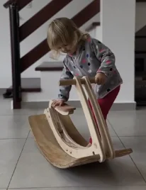
For my first CNC machining experience, I decided to make something simple and practical. Because the lab and CNC machine are located in another city, I needed a design that is movable and easy to transport back home. I also wanted a result that can be displayed at school, so the target was a balance between practicality and visual interest.
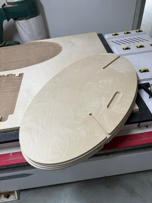
Computer-controlled machining (CNC) week introduced the process of using a large-format CNC router to precisely cut complex shapes from sheet material. Unlike hand tools, the CNC router is guided entirely by a digital file, allowing organic curves, tight tolerances, and repeatable results that would be impossible to achieve manually. The week's assignment was to design and mill something that could not be made easily by hand – something that demonstrated the true capability of the machine. The chosen project was a press-fit stool: all pieces cut from a single 18 mm birch plywood sheet, assembled without glue or screws.
To reach focus state while working on concept selection, I used background music: https://www.youtube.com/watch?v=WSXdH5SzNBs
Inspiration and Sketch Design
Inspiration
Pinterest was used as the primary visual reference source to review different CNC furniture concepts and evaluate what can be realistically produced in this week. The design workflow is similar to laser-cutter planning, but scaled for larger stock and assembly constraints.
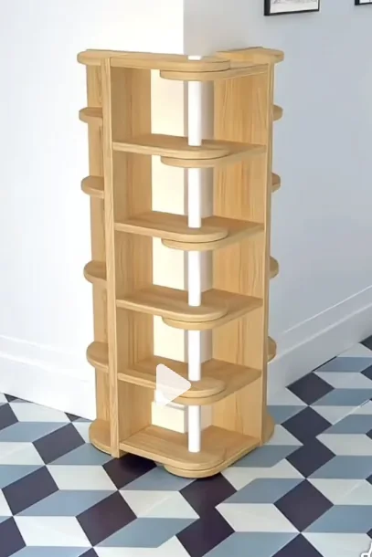
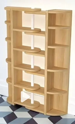
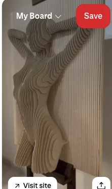
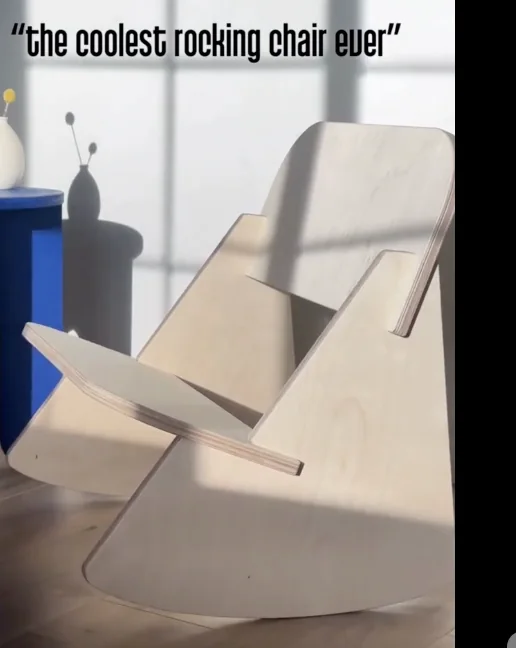


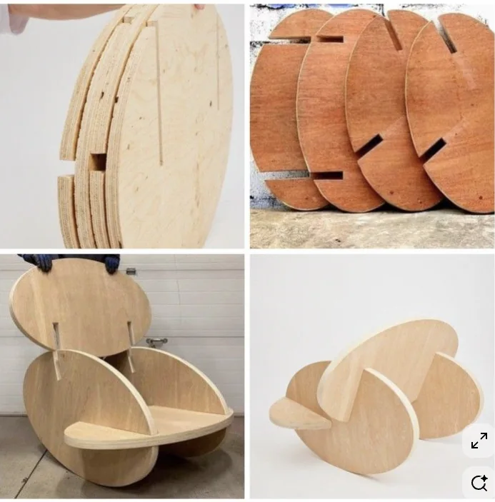
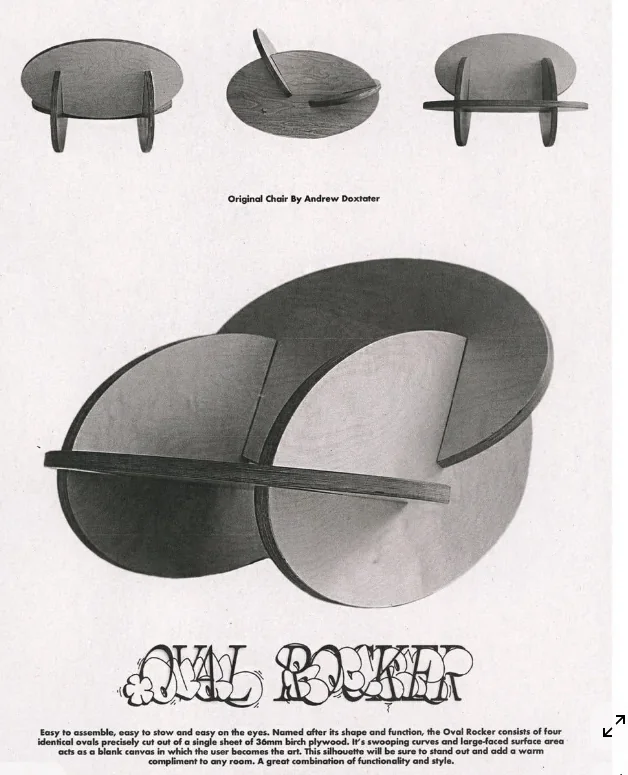
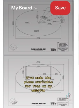
There are many interesting projects and it is easy to over-scope design ideas. For a practical fabrication plan, I selected an oval rocker-chair direction that is visually strong but still feasible for the current machining stage.
Key reference: https://www.andrewdoxtater.com/work/ovalrockerdiy
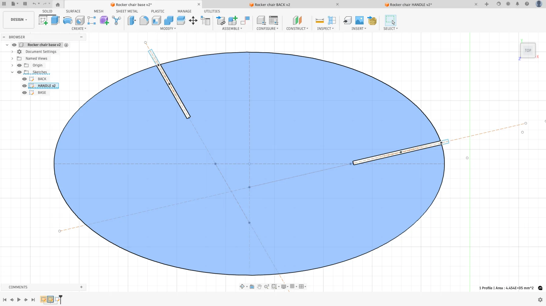
Sketch Design
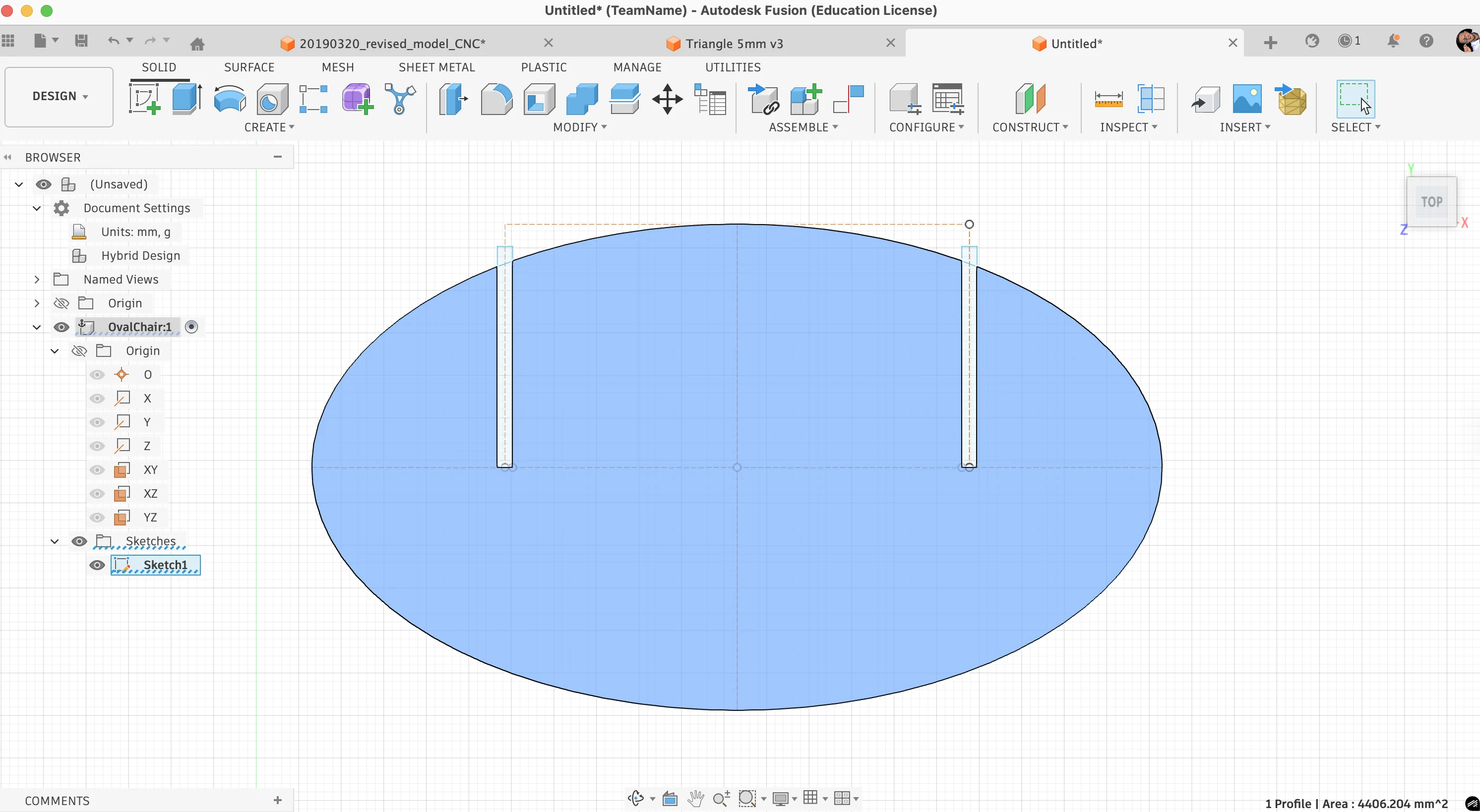
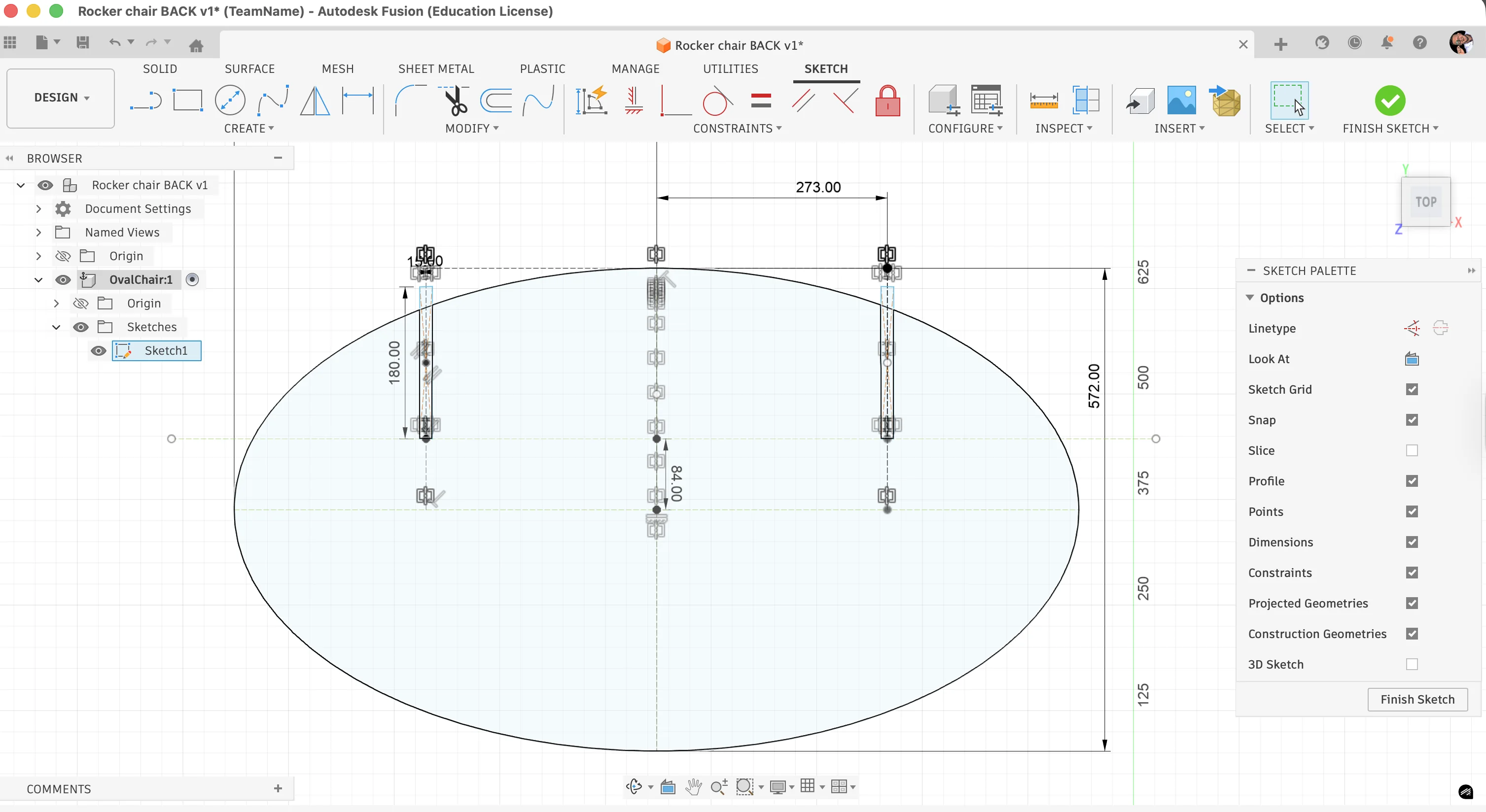
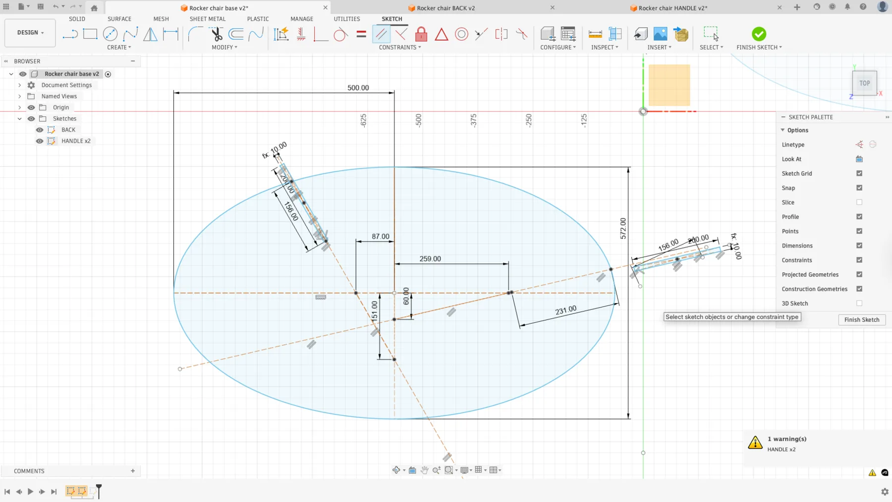
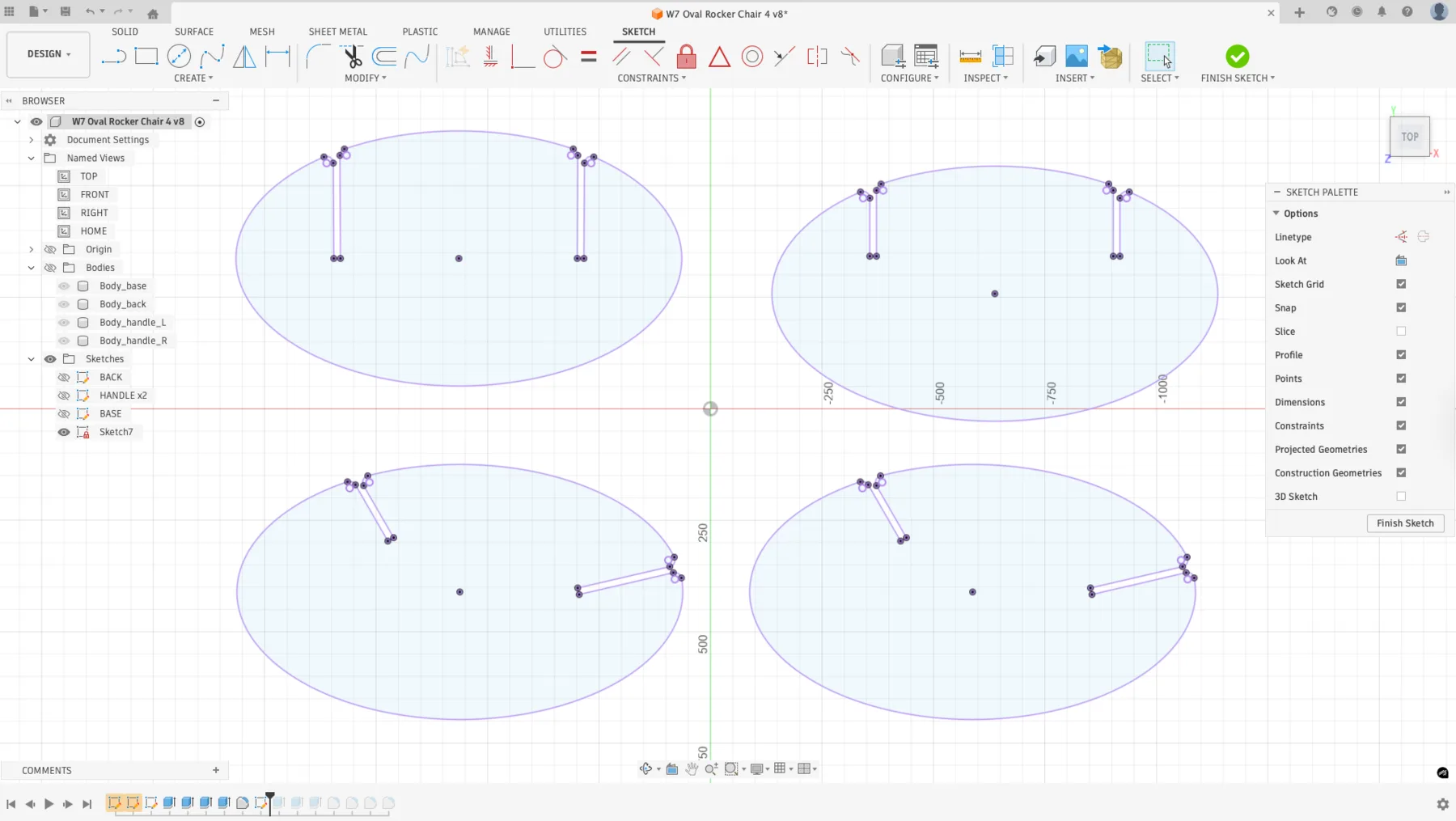
In Fusion, I created an ellipse with dimensions 572 x 1000 mm. A vertical and horizontal construction centerline was added to improve navigation and symmetry control.
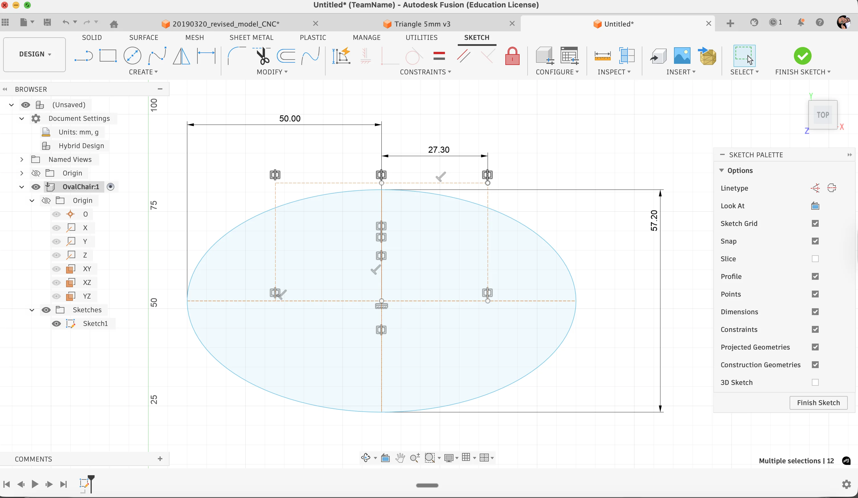
I allocated 273 mm distance for the joint notch area. The ellipse was cut using rectangular profiles (15 mm x 260+). Midpoint and coincident constraints were used to connect the rectangle geometry accurately.
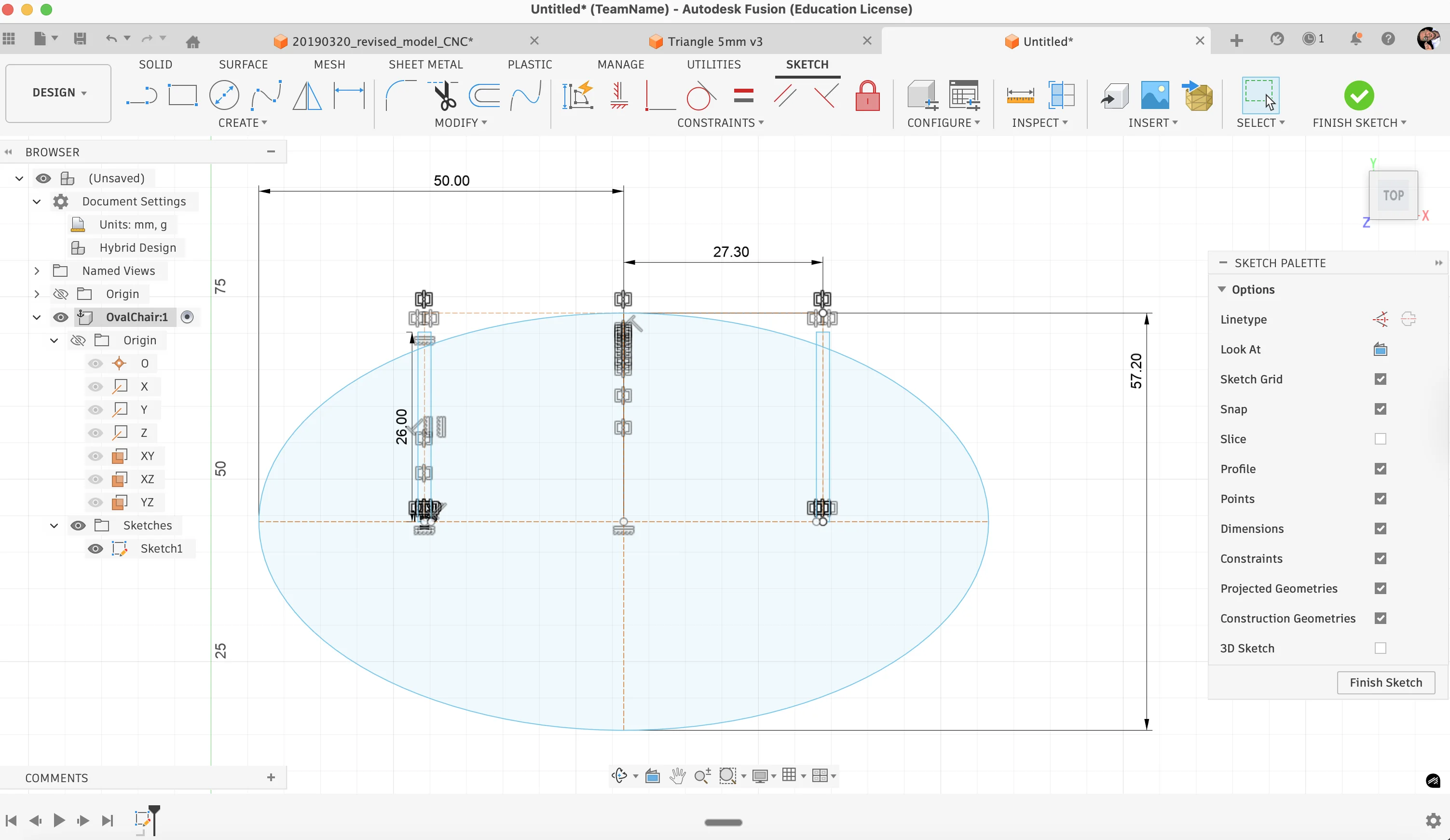
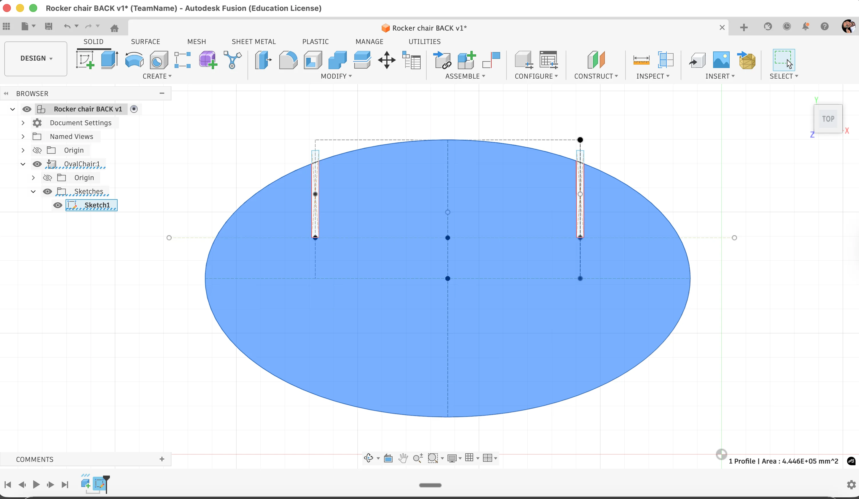
The base side was completed first.
The back side followed with a similar workflow by adding another construction line and adjusting constraints.
The handle area needed a slightly different approach because the stop geometry used different angles. I adjusted the sketch points, connected them with a reference line, and then built the rectangle from a center point so the constraints remained easier to control.
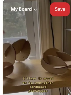
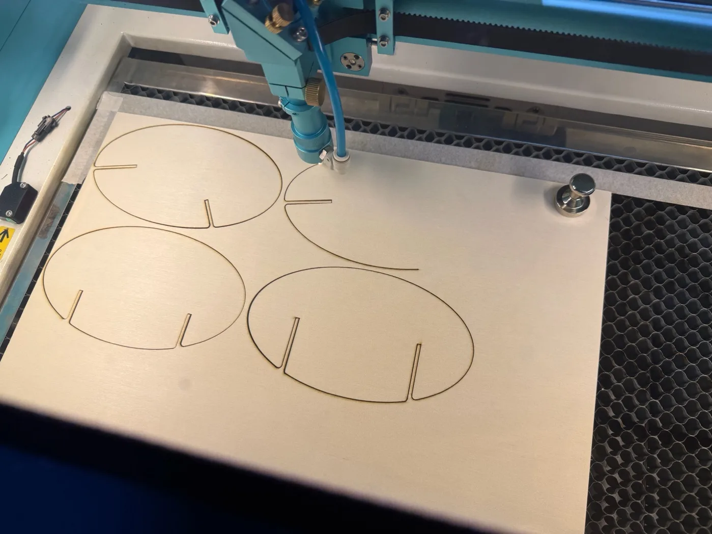
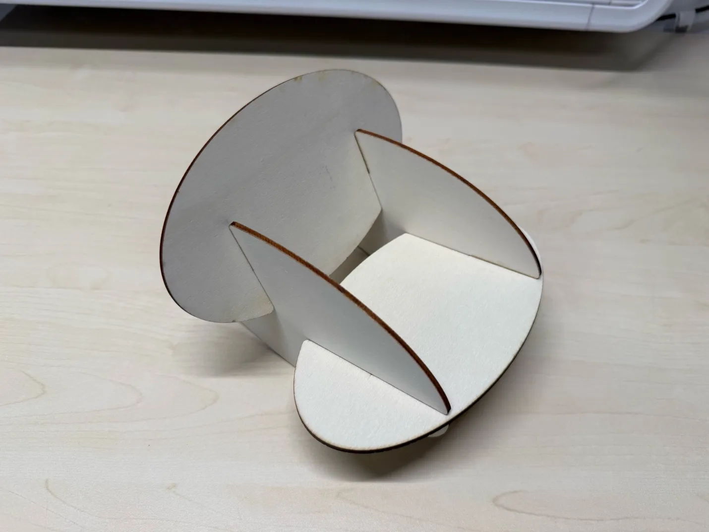
Before sending the design to the large CNC, I made a small-scale prototype on the laser cutter. This was a quick way to test the rocking motion and check whether the joints behaved as expected.
The first miniature exposed a dimensional shift in one area, so I corrected the sketch and cut the test again. After the second version assembled properly, the design was ready for full-scale machining.
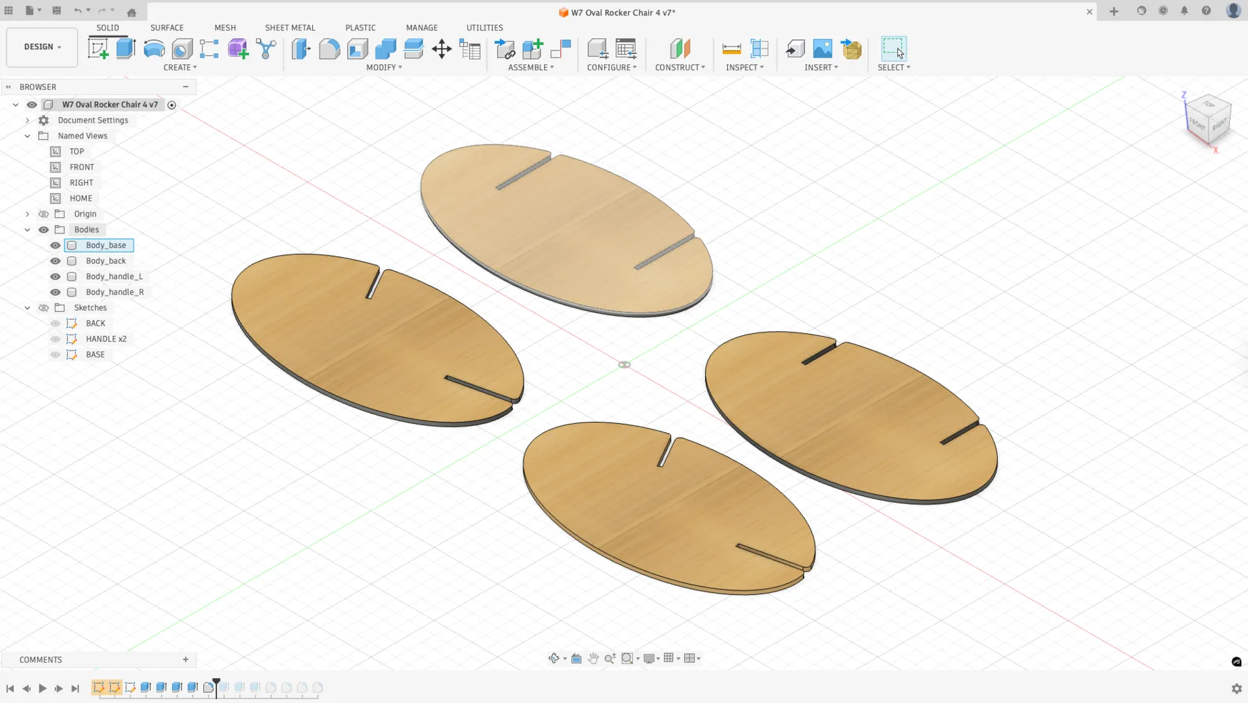
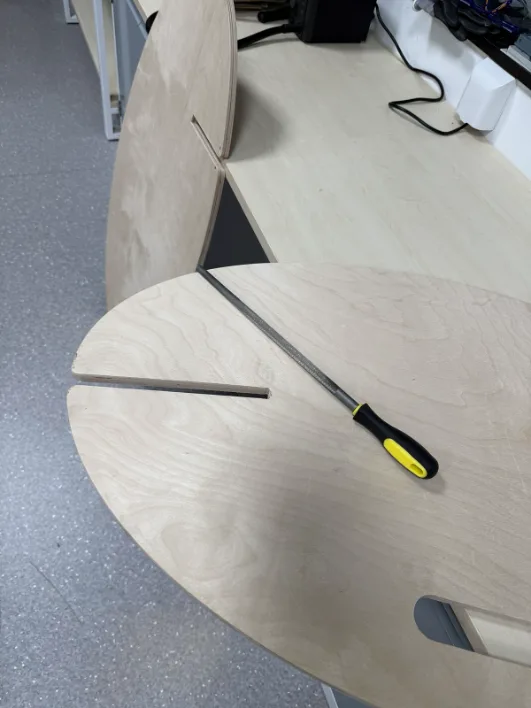
Dogbone Preparation
For press-fit joints on a CNC router, dogbones are important because the round end mill cannot produce a sharp internal corner by itself. Adding these reliefs gives the mating part enough clearance to fit cleanly.
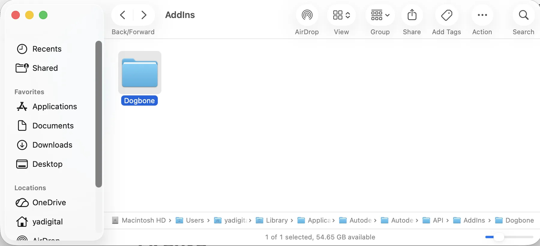
I used the Fusion 360 dogbone plug-in and applied it to the joint locations that needed internal corner relief. The plug-in reference I used was: https://tapnair.github.io/Dogbone/
After that, the sketch was ready and I moved on to machine setup and CAM preparation.
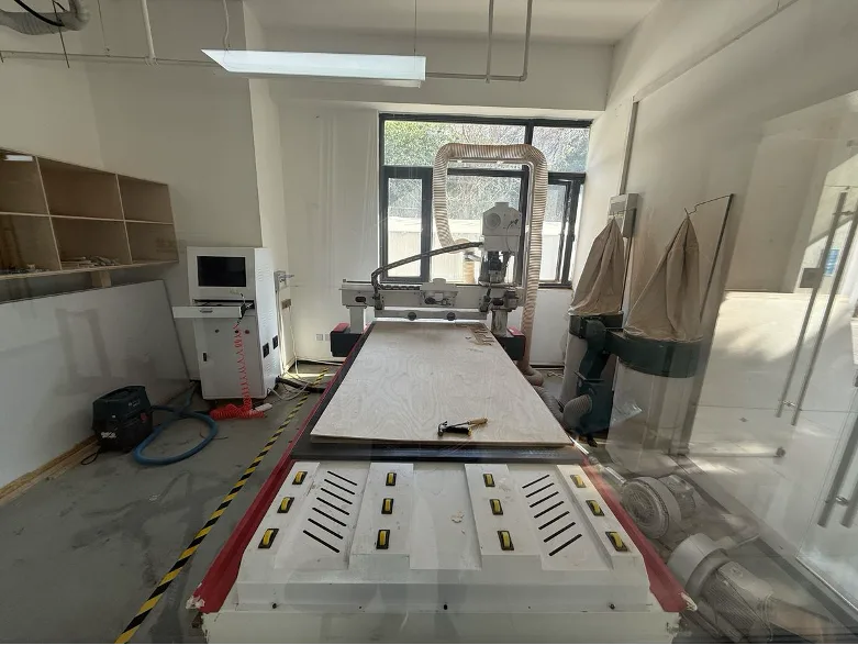
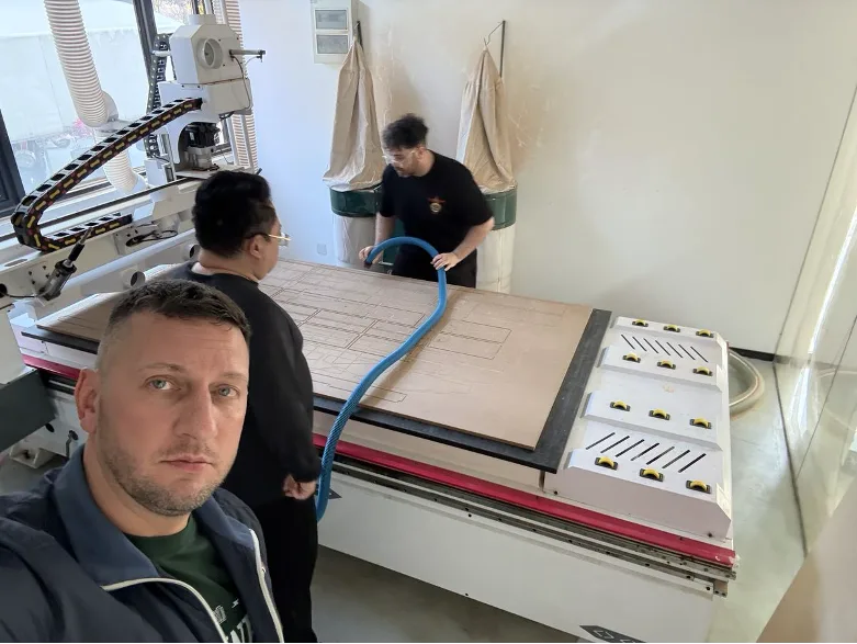
The CNC Machine
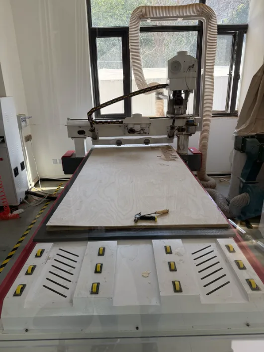
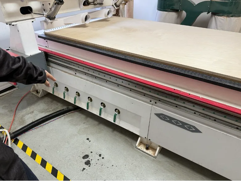
The FormShop CNC router is a large-format 3-axis machine with a vacuum hold-down bed sized for a full 2440 x 1220 mm plywood sheet. The vacuum table secures the material without clamps, while the dust collection system removes chips during cutting.
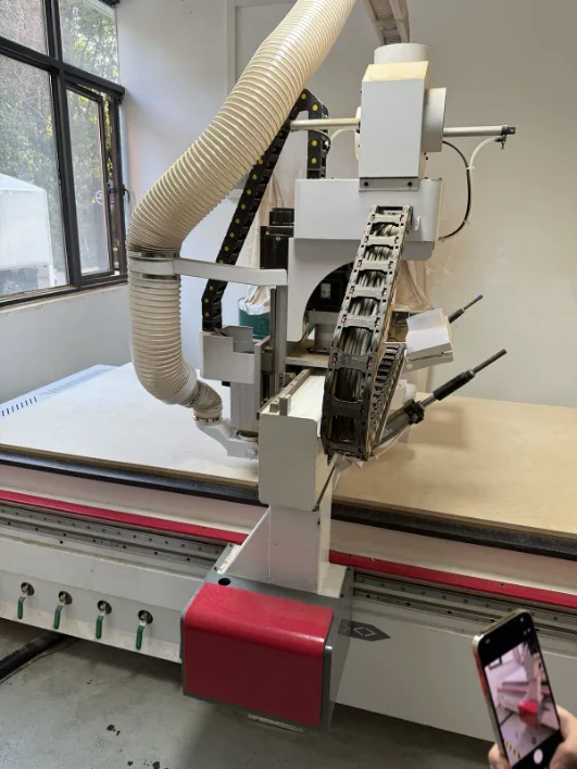
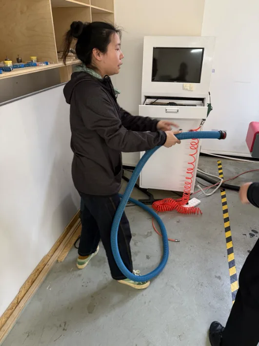
The machine is controlled from a dedicated side computer that loads the toolpath file and manages jogging, zeroing, and running the job. During training, I also reviewed the spindle, collet system, and basic setup workflow before starting production.
Preparing the Machine
Before running the job, we followed the normal preparation sequence: clean the vacuum bed, place the plywood sheet, switch on the vacuum zones, and check the cutting tool and probe. Doing this carefully helps the material sit flat and keeps the machining conditions stable.
Cleaning the Vacuum Bed
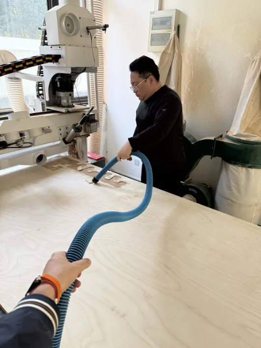
The first step was cleaning the bed surface. Sawdust and leftover chips from the previous job had to be removed so the plywood could sit properly and the vacuum hold-down would work evenly.
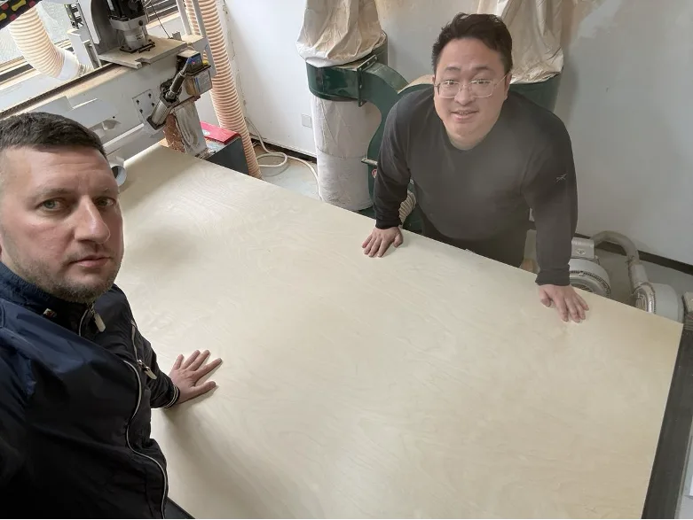
Loading the Sheet Material
Once the surface was clean, a full 18 mm birch plywood sheet was aligned on the bed. After that, the green vacuum zone valves were opened so the machine could hold the material securely during cutting.
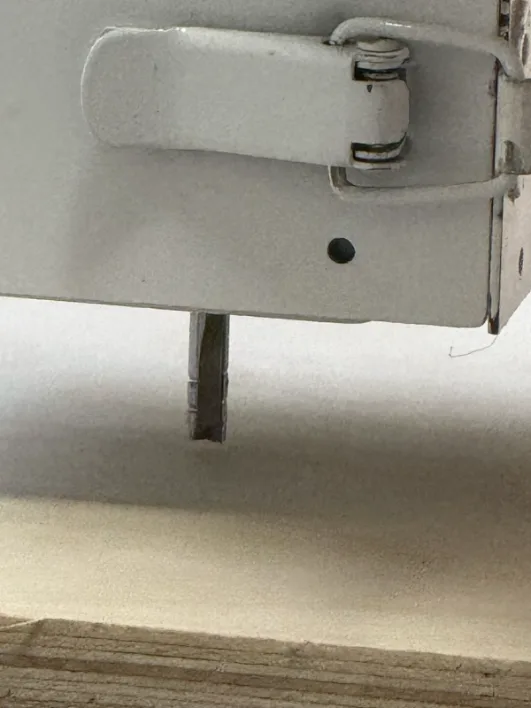
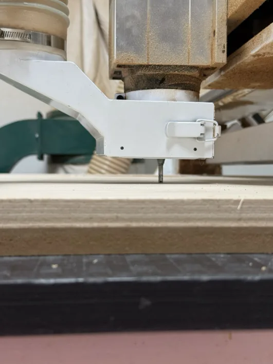
The End Mill
For this job we used a 6 mm single-flute upcut end mill. The bit was installed in the spindle collet, and then the probe was positioned so the machine could measure the top surface accurately before cutting.
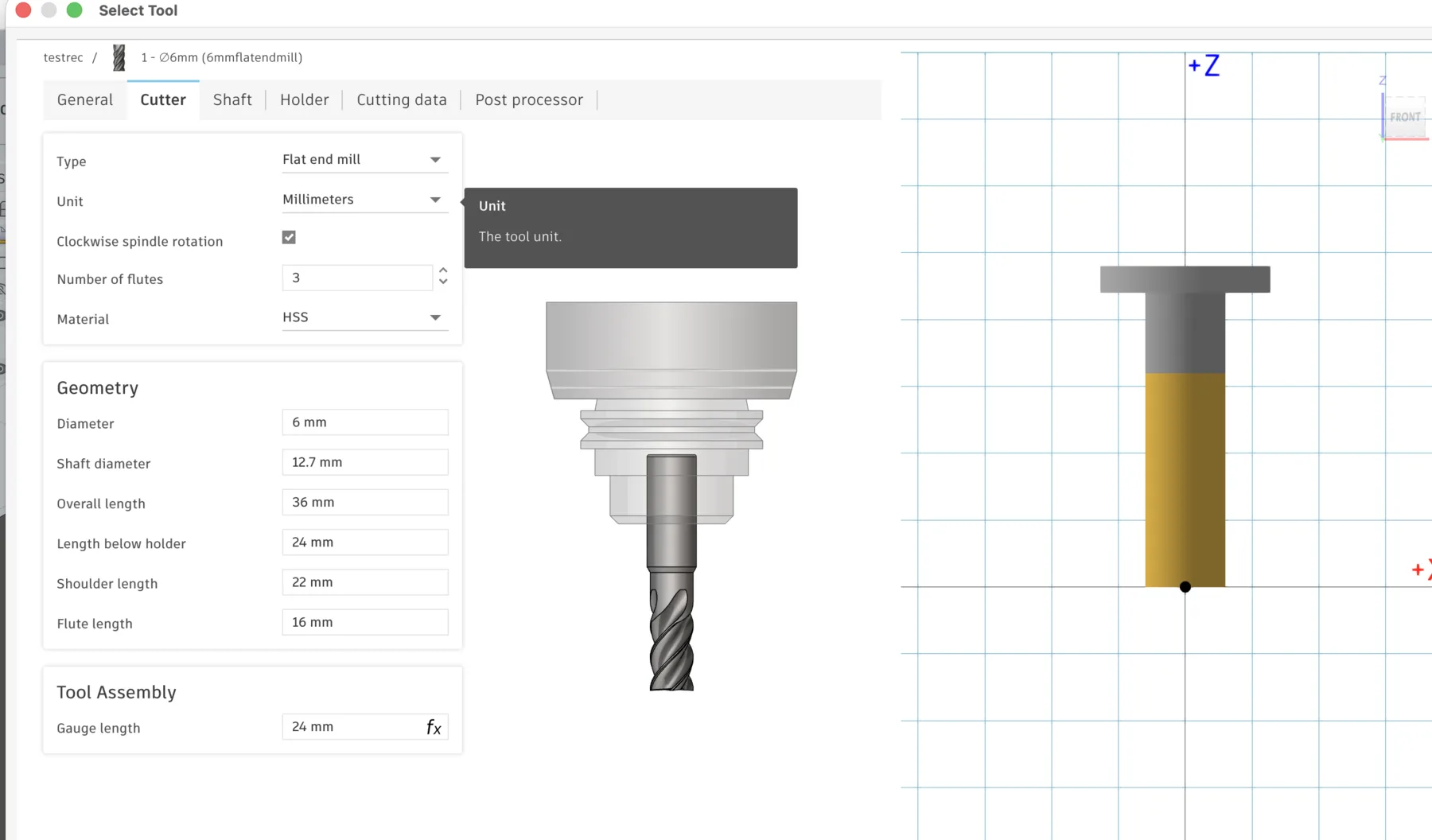
CNC Tool Installation in Fusion 360
During the training, I also learned how to define the cutting tool in Fusion 360. The vendor tool parameters can be entered directly so the digital tool matches the real bit installed in the spindle.
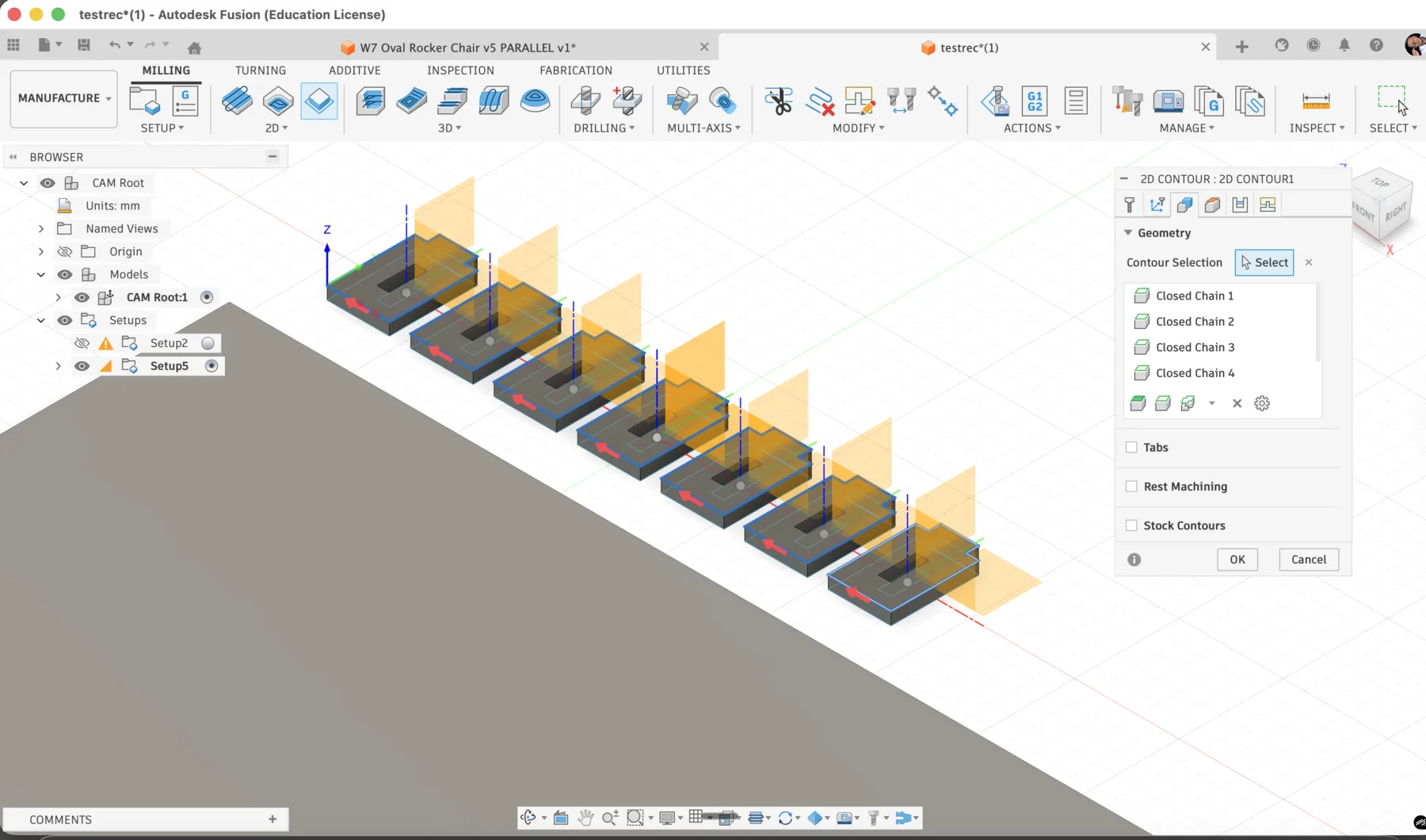
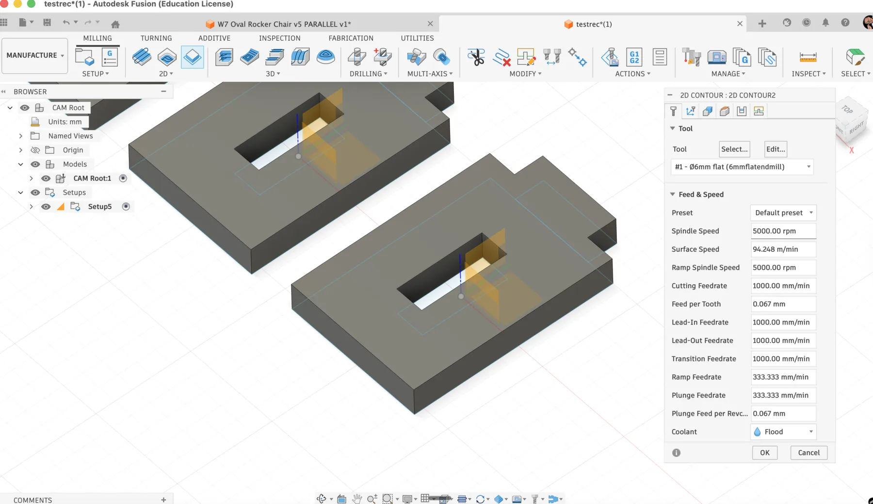
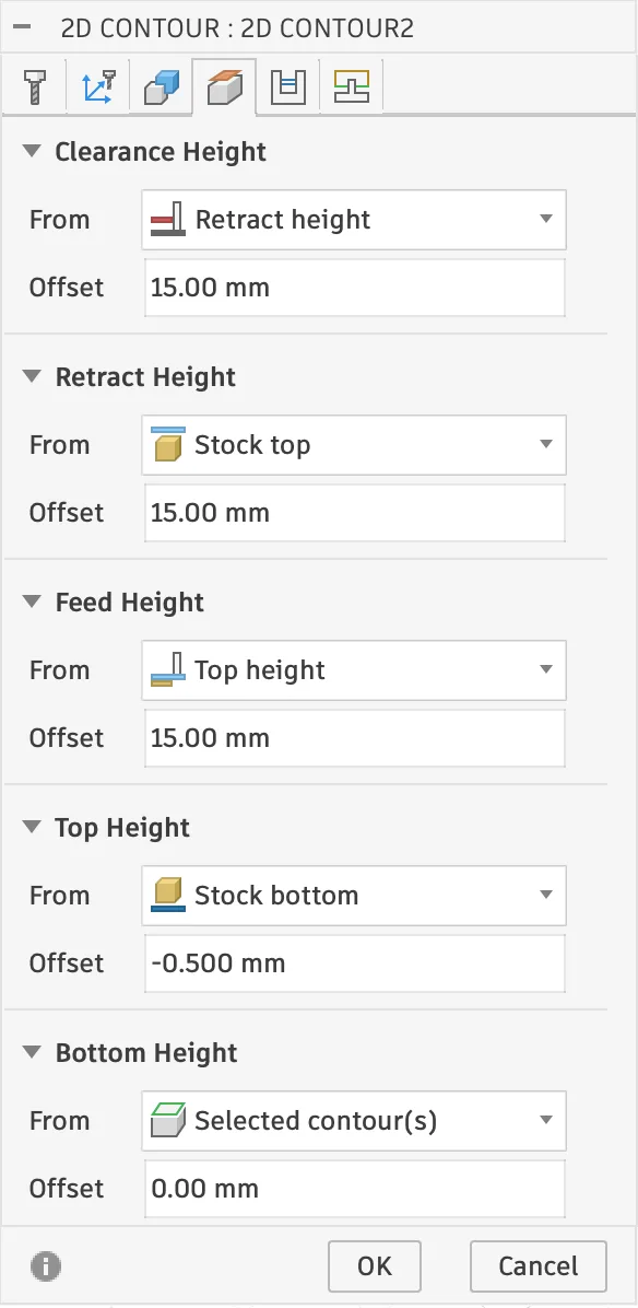
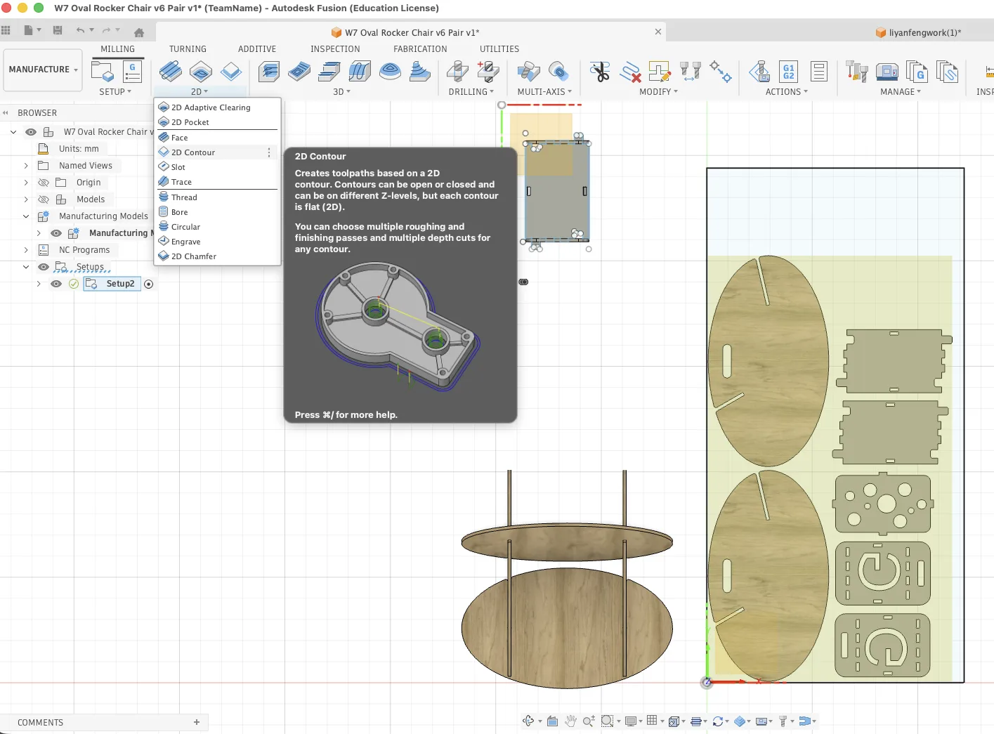
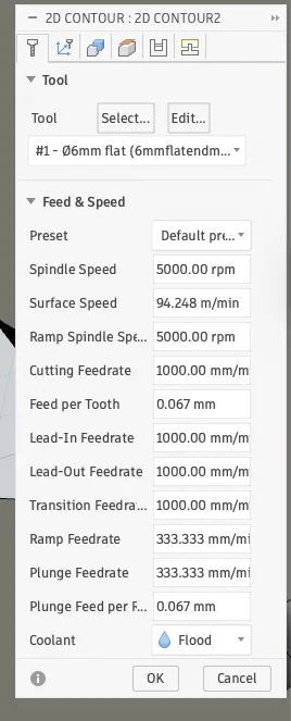
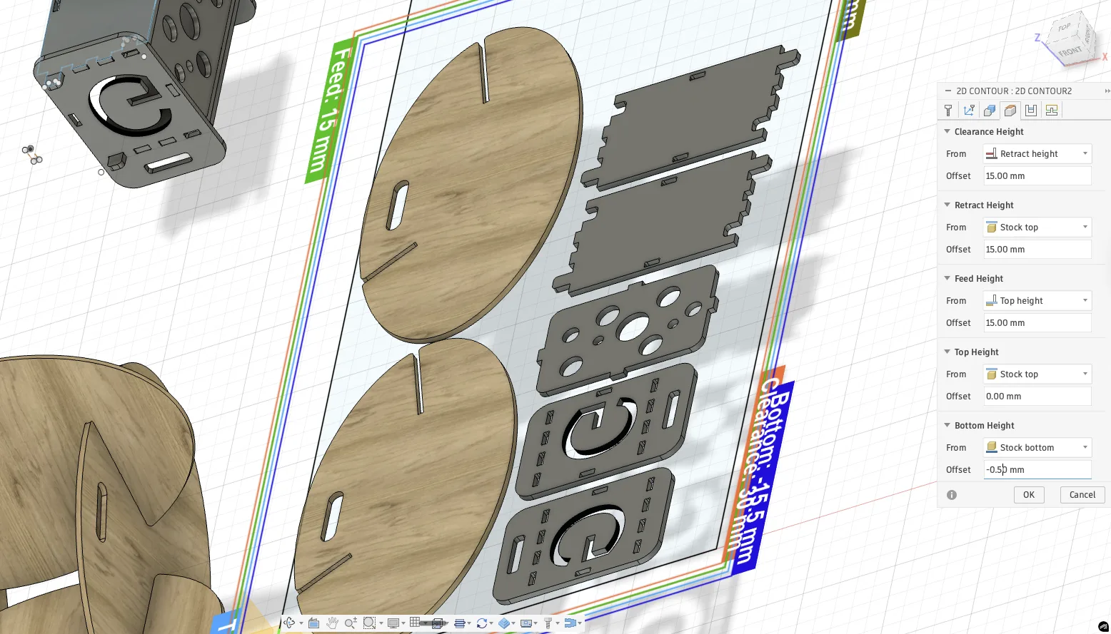
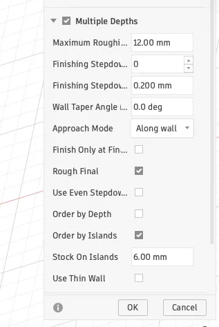
Setting the CAM Toolpath in Fusion 360
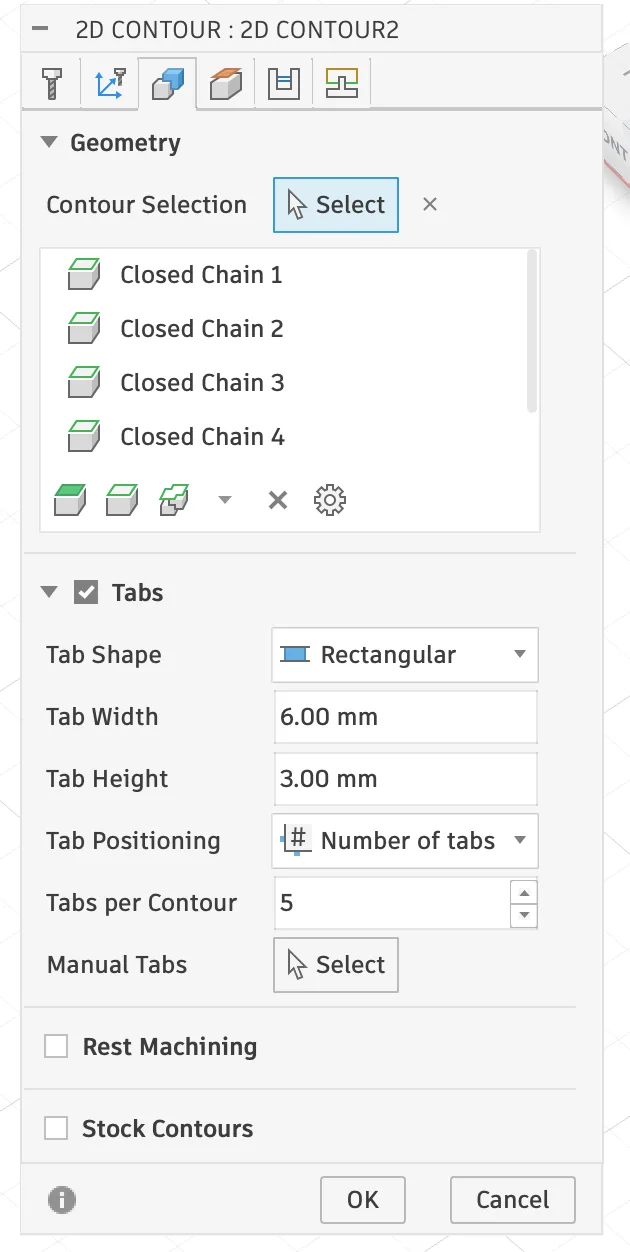
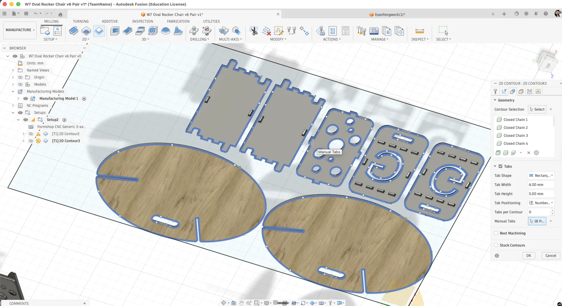
Before machining, the design had to be converted into a 2D contour toolpath. This is the standard operation for cutting profiles from sheet material.
- Tab width: 4.00 mm
- Tab height: 5.00 mm
- Tabs per contour: generated according to the contour length
- Cut depth: full material thickness in multiple passes
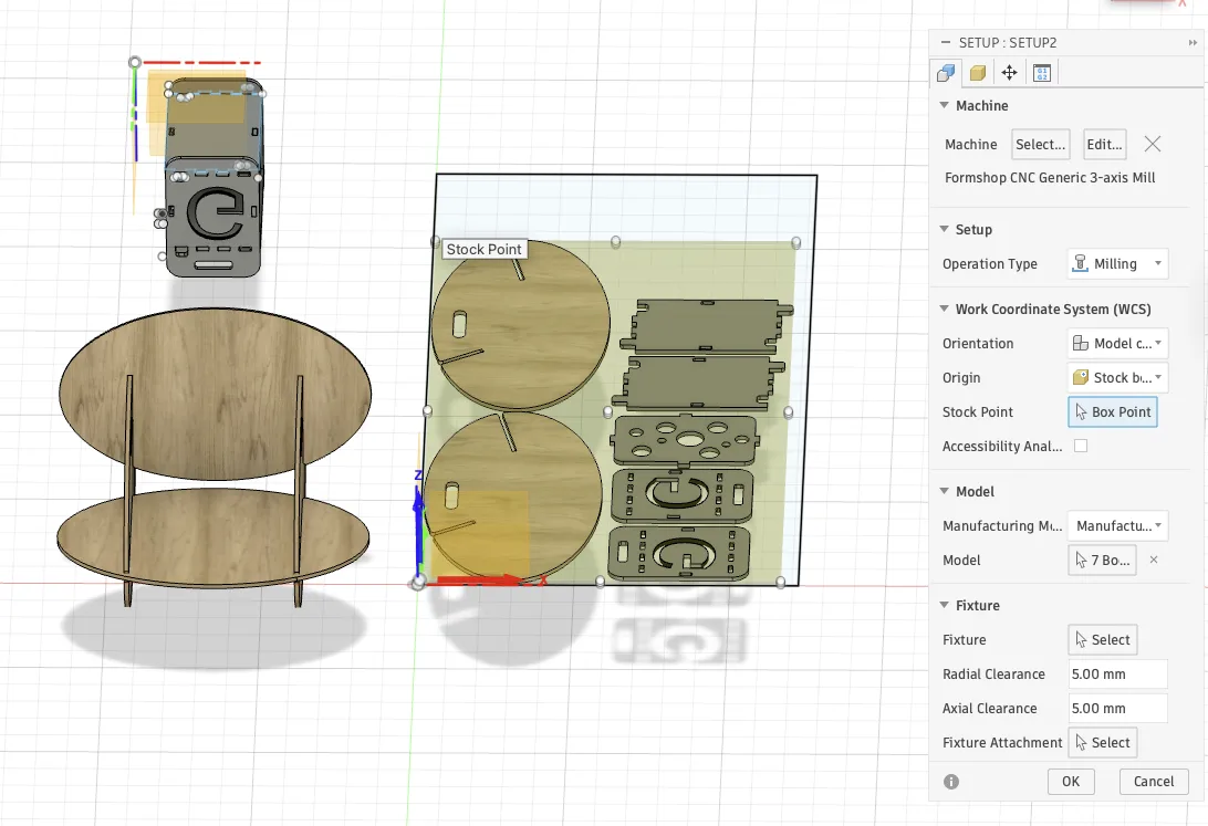
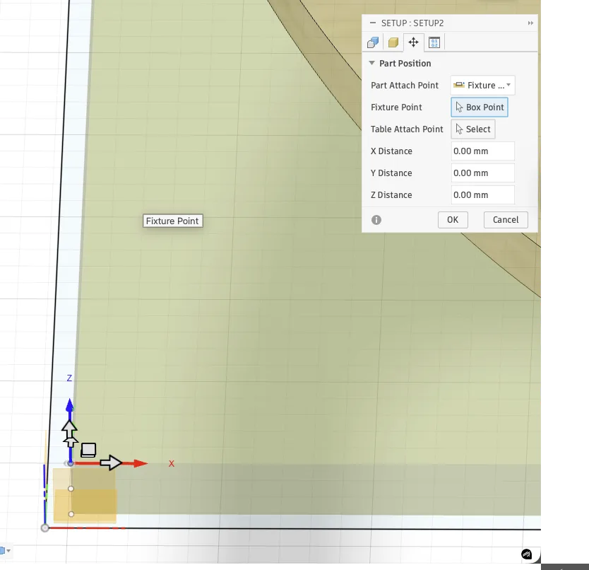
Setting Work Origins
The machine also needed a precise start point. The XY origin was set from the front-left corner of the sheet, and the Z origin was taken from the top surface using the probe so the spindle could recognize the material height correctly.
Test Cuts
We also made test cuts before the final job. This step helped confirm that the cutting depth, feed rate, and spindle speed were behaving correctly on the chosen plywood.
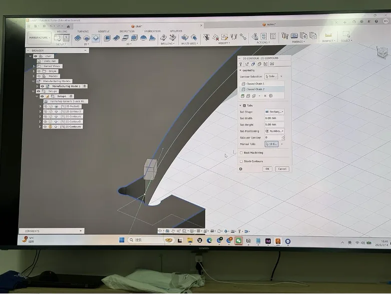
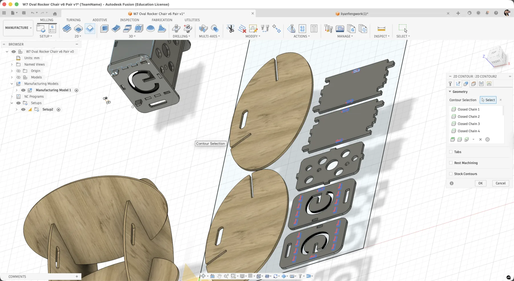
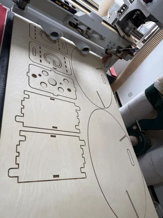
CNC Nesting
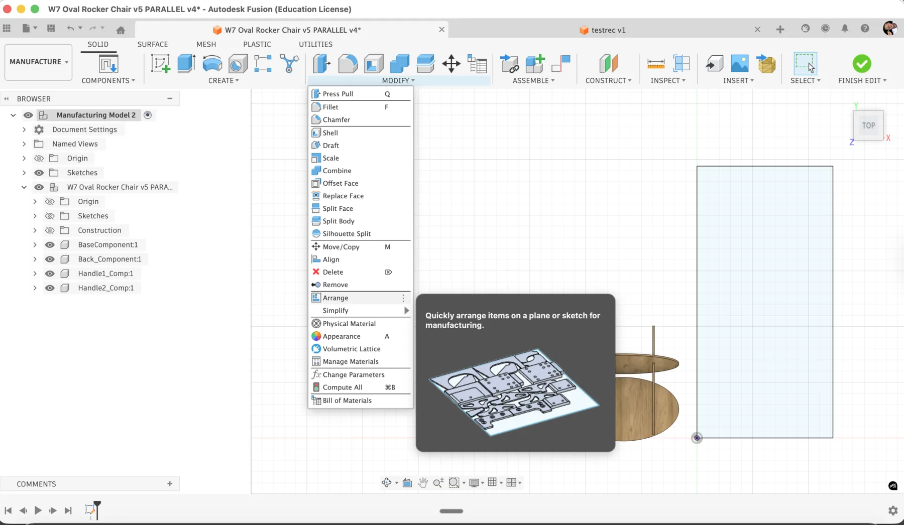
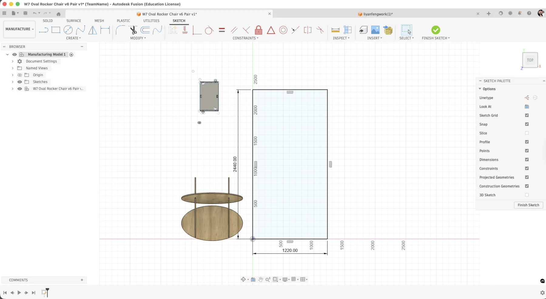
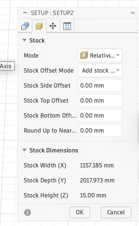
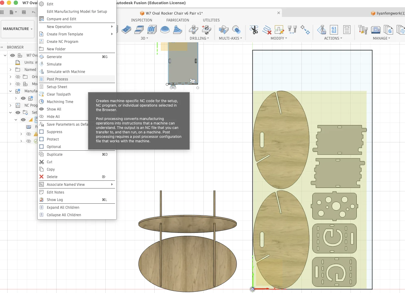
In Manufacture mode I created a separate manufacturing model so the parts could be arranged for machining without changing the original design. A 2440 x 1220 mm sheet outline was added as the reference stock size.
This step is essentially nesting. I arranged my parts on the sheet and then coordinated with my classmate Yanfeng so both projects could share the plywood efficiently and reduce waste.
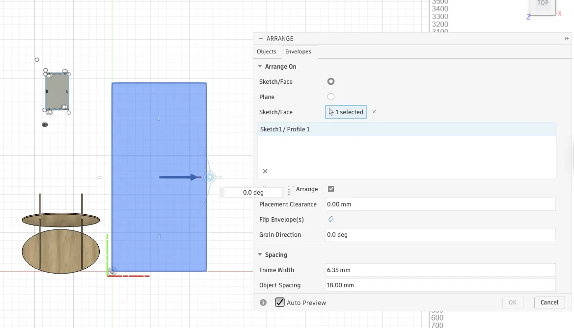
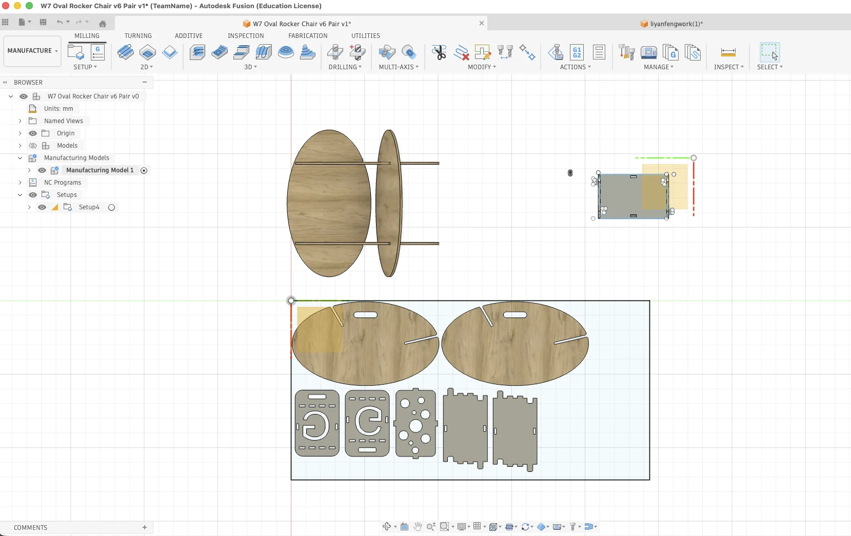
Arranging all parts took some time because clearance, orientation, and shared sheet usage all had to work together. Once the layout was stable, I generated the actual 2D contour operations.
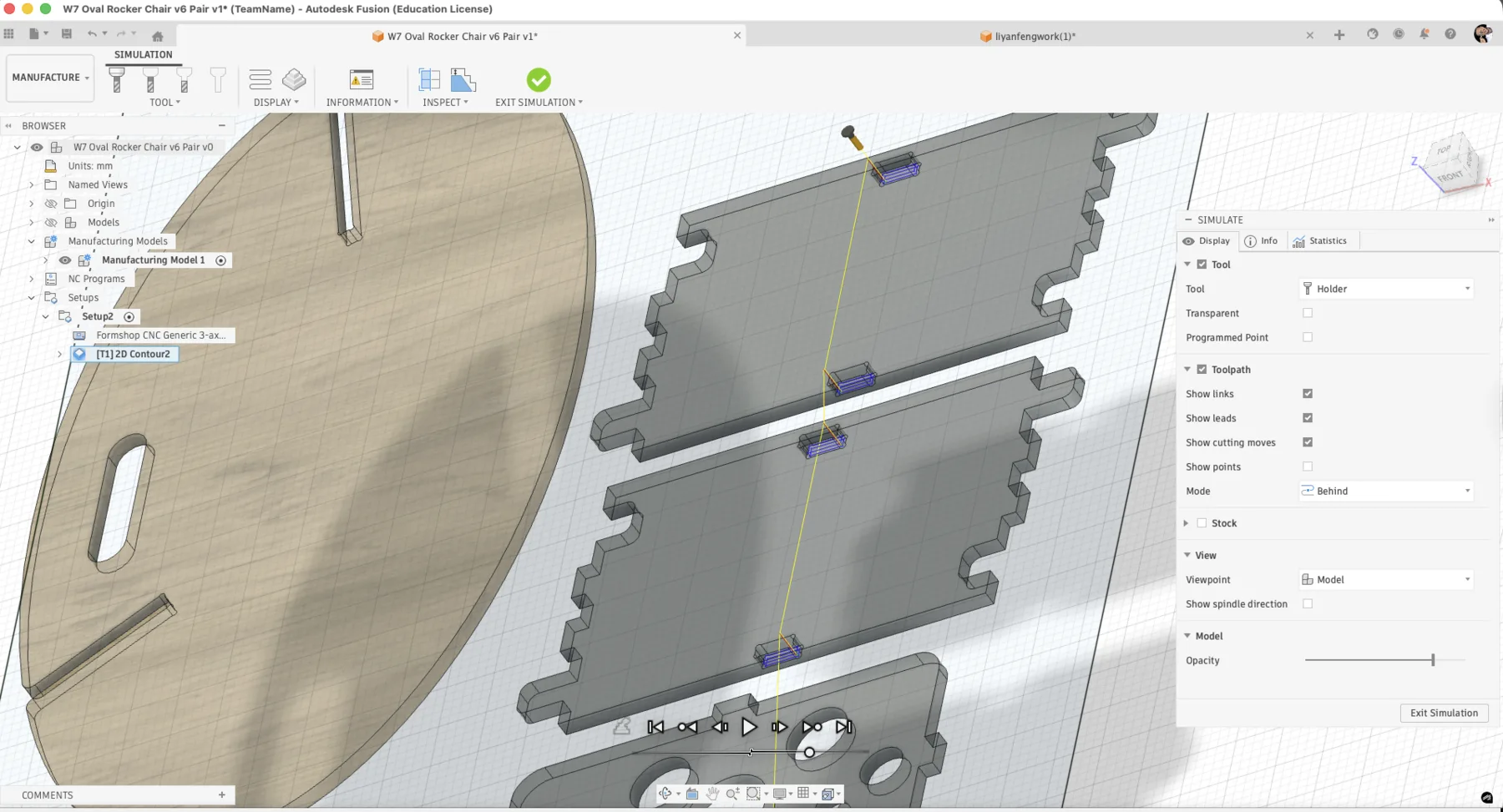
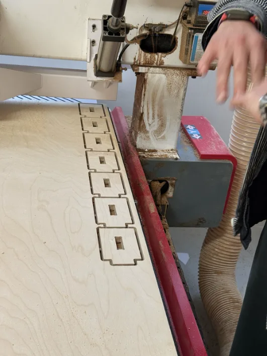
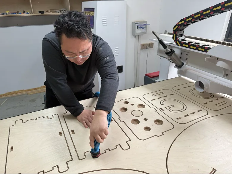
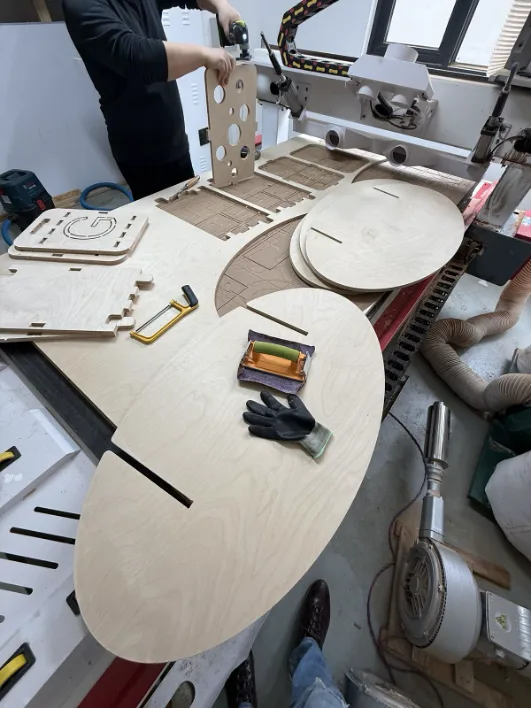
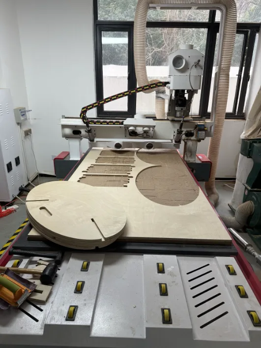
Cutting
Once the file was ready, the plywood sheet was placed on the vacuum bed and the job could begin. The combined nesting layout allowed both sets of parts to be cut from the same sheet with less waste.
During operation we stayed in the safe area and kept distance from the moving spindle. Even with the machine enclosure, proper positioning and attention are still important for safety.
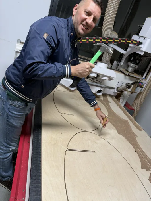
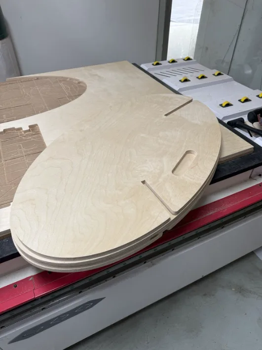
Removing Parts and Testing
After the cut completed, the vacuum was turned off and the sheet was removed from the bed. The tabs kept the parts stable during machining, so they had to be snapped or trimmed away afterward.

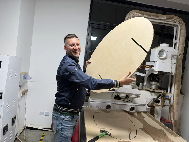
Assembly and Final Result
During assembly I discovered that one joint was tighter than the others. At first I thought sanding would be enough, but after checking the geometry I saw that one slot was actually smaller. I corrected the mismatch and continued the assembly from there.
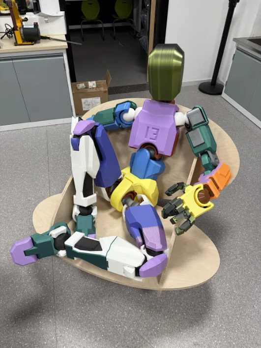
After the fix, the chair assembled successfully and the rocking motion worked as intended. The final result kept the original design idea while also proving that the full CNC workflow, from sketch to nesting to assembly, worked correctly.

Reflection
This week was both interesting and challenging because it was my first time working with a large CNC machine in a complete workflow, from design preparation to machining and assembly. Setting up the tool, cleaning and preparing the bed, defining origins, and running the cut were all new experiences for me. It helped me understand much better how a full-size CNC router operates and how much attention is required at each stage before the machine can actually start cutting.
I also learned that working with a machine like this is not only about the software or the design file, but also about process, safety, and teamwork. This CNC cannot be operated alone, so it always requires another person during setup and cutting, which made the workflow feel much more disciplined and collaborative. At the same time, this experience gave me a clearer understanding of how smaller CNC machines work, because the same logic of tool setup, zeroing, toolpaths, and material holding applies there as well.