Week 12 — Mechanical Design & Machine Design
Group assignment
- Mechanical Design (part 1 of 2): Design a machine that includes mechanism + actuation + automation + application.
- Mechanical Design (part 1 of 2): Build the mechanical parts and operate it manually.
- Mechanical Design (part 1 of 2): Document the group project.
- Machine Design (part 2 of 2): Actuate and automate your machine.
- Machine Design (part 2 of 2): Document the group project.
Group contribution roles
This table records the group members, their main roles, and the page/reference where the contribution is documented. Section 4.1 later expands this into the detailed task allocation.
|
Person |
Role |
Page / reference |
|
Yaroslav Artsishevskiy |
Idea, documentation, electrical design |
|
|
James Stewart |
Assembling and testing, poster design |
This group documentation page |
|
Winnie Sun |
Project organization, video editing |
|
|
Yanfeng Li |
Arduino board container 3D modeling |
This group documentation page |
|
Zequan Lin |
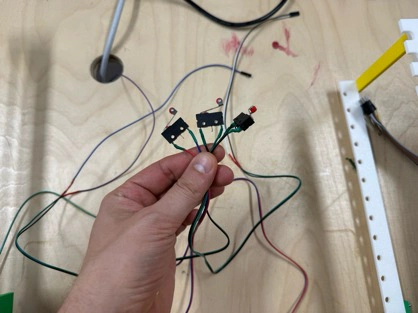
Accessory design for protecting wires |
Individual assignment
- Document your individual contribution.
Learning outcomes
- Work and communicate effectively as a team.
- Design, plan, and build a machine.
- Analyse and solve technical problems.
- Recognise opportunities for improvements in the design.
Slide
Final video
Documentation
FAB ACADEMY 2026 • Mechanical Design & Machine Design
Week 12
Mechanical Design & Machine Design
— Group Project —
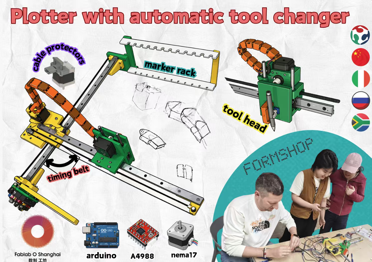
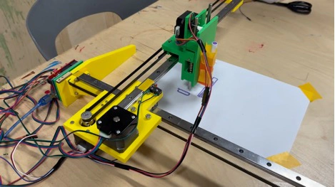
The Coloured Plotter · a CNC drawing machine with an automatic tool changer
1. Assignment brief
This week is split into two parts that together make up a single group deliverable. In Part 1 — Mechanical Design we had to design a machine and build it, and operate it manually. In Part 2 — Machine Design we had to actuate and automate the same machine so it can run on its own. Section 13 separates out what my individual contribution was and how I understood the process.
|
• Mechanical Design (Part 1) — Design a machine that includes mechanism + actuation + automation + application. • Mechanical Design (Part 1) — Build the mechanical parts and operate it manually. • Mechanical Design (Part 1) — Document the group project. • Machine Design (Part 2) — Actuate and automate your machine. • Machine Design (Part 2) — Document the group project. Reference: fabacademy.org/2026/nueval/mechanical_design,_machine_design |
2. Brainstorming — how we picked the machine
Before touching a single motor we spent a couple of evenings just talking. Our group is not in a single lab: teammates work from different cities, so we met online almost every day and met in person when we could. That constraint shaped the conversation — whatever we built had to be simple enough that a single person in the lab could move forward while the others designed or sourced parts remotely.
We listed a handful of ideas — a small pick-and-place, a marble sorter, a fibre-winding rig, a coffee-art machine — and rated them on four axes: mechanism complexity, motor & driver count, material/BOM cost, and "is the final demo actually fun to watch?". The winner was a drawing machine — a plotter. A plotter gives us every sub-system Fab Academy wants us to touch (a mechanism, actuation, automation, and a clear application) while still being cheap, safe, and visual.
|
Why a plotter? • Clear mechanism — two orthogonal axes plus a pen-lift. Each sub-system is easy to reason about in isolation. • Affordable BOM — we could source most parts in-lab: recycled steppers, GT2 belts, 3D-printed brackets. • Fun application — drawings on paper are immediate feedback; a good machine produces a poster-worthy demo. • Split-able work — CAD, firmware, electronics, and artwork are mostly independent, so remote teammates aren't blocked on each other. |
3. Warm-up — the Mini CNC Plotter
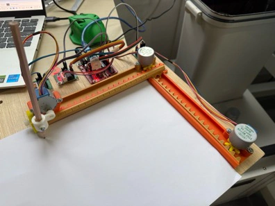
To get a working baseline as fast as possible, I built a small 2-axis CNC plotter driven by an Arduino Nano and a CNC shield. The idea was not to produce our final machine, but to run through the full toolchain — CAD → G-code → firmware → motion — once, end-to-end, so that every person on the team would understand where each piece slots in.
I took the 3D-printed mechanical design from Thingiverse and the 28BYJ-48 GRBL port from a public GitHub repo as my two references:
• 3D-printed mechanical parts — thingiverse.com/thing:4579436
• GRBL port for 28BYJ-48 steppers — github.com/TGit-Tech/GRBL-28byj-48
3.1. Bill of materials
|
Part / Component |
Qty |
Notes |
|
Arduino Nano (clone or original) |
1 |
Main controller |
|
CNC Shield v3 (or hand-wired driver board) |
1 |
Breakout for stepper drivers |
|
A4988 stepper drivers |
3 |
Micro-stepping set to 1/16 |
|
28BYJ-48 stepper motors (5 V) |
3 |
Re-wired to bipolar mode |
|
3D-printed frame parts (Thingiverse #4579436) |
1 set |
PLA, 0.2 mm layer |
|
M3 screws & nuts, linear rods, bearings |
as needed |
Hardware |
|
F/F jumper wires |
as needed |
Female-to-female wires, 10 cm and 20 cm lengths |
|
Ballpoint / fineliner pen |
1 |
Drawing tool |
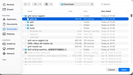
3.2. Flashing GRBL onto the Arduino
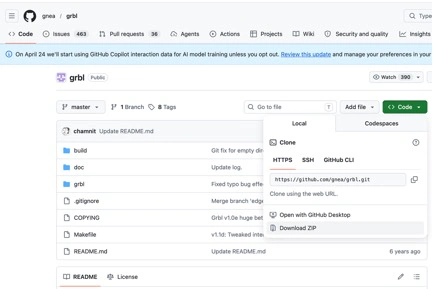
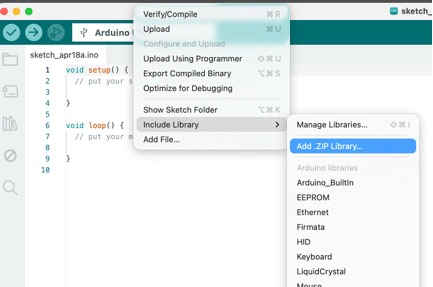
I used the mainline GRBL 1.1h firmware from github.com/gnea/grbl. The flow was: download the repo as a ZIP, open the Arduino IDE, go to Sketch → Include Library → Add .ZIP Library, and point it at the grbl/ sub-folder (not the repository root — that's the single most common mistake with GRBL).
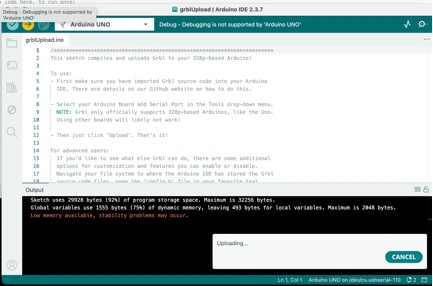
From there, File → Examples → grbl → grblUpload opens a sketch that looks suspiciously short (basically two lines). That's fine — all of GRBL's logic lives in the library itself, the sketch is just the entry point. I selected the board (Arduino Nano, ATmega328P Old Bootloader depending on the clone), selected the COM port, and hit Upload.
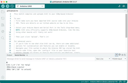
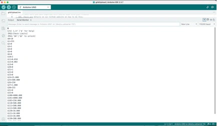
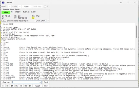
3.3. GRBL configuration ($$ settings)
After flashing, I opened the Serial Monitor at 115200 baud and typed $$ to dump the current settings. GRBL's defaults are for a much bigger machine, so several values need tuning for a 28BYJ-48 + A4988 setup.
|
Which settings matter the most • $100 and $101 — steps per mm on X and Y. These are the first thing to calibrate (we measure a commanded move vs. actual travel and correct the ratio). • $110 and $111 — max travel rate. 28BYJ-48 motors skip above ~600 mm/min, so keep these conservative. • $120 and $121 — acceleration. Again, conservative or the pen drags. • $30 — max spindle / Z servo PWM. Needed once we swap to the servo-GRBL branch. |
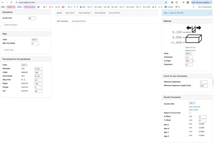
3.4. Universal G-code Sender (UGS) + JSCUT
For sending G-code I used Universal G-code Sender (UGS). It's a Java app that lets you connect to a GRBL board, jog the machine, home it, and stream a .gcode file while watching progress in real time.
To generate the G-code itself I used JSCut — a browser-based CAM that takes an SVG and spits out a G-code file. For line-art I kept it simple: import SVG, pick "engrave", set the pen-up / pen-down Z heights, export.
3.5. First drawings and what I learned
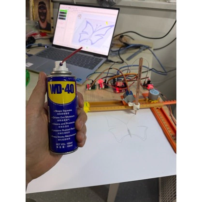
The orange warm-up plotter drawing its first butterfly — a drop of WD-40 on the rods was the difference between jittery lines and clean ones.
The clean final drawing from the warm-up was less important than the behaviour we observed while making it: the machine could follow G-code, but the line quality immediately showed where the mechanics were weak.
Takeaway: the mini plotter works, but it is honestly painful to watch. 28BYJ-48 motors are geared-down by design, so max feed rate is tiny. The print area is only a few centimetres wide. And it only knows one pen. That is exactly why we decided to build a second, much better plotter as our actual group deliverable.
|
Maintenance tip that bit us Always lubricate linear rods before the first real print. Our first "completed" drawing on the warm-up had visible jitter because the Y rod was dry and stuttering on the printed bearings. A shot of WD-40 fixed it (see photo above). |
4. The Automatic tool changer Plotter — the real group project
After the warm-up, we upgraded the ambition. The group goal became: a belt-driven XY pen plotter with an automatic tool changer that can swap between multiple pens mid-drawing. That gives us colour — and the automation step (Part 2) becomes genuinely non-trivial, since the machine has to release one pen, park it, pick up another, and carry on.
Reference design we based ours on: HowToMechatronics — DIY Pen Plotter with Automatic Tool Changer. We did not clone it one-to-one — we re-drew the brackets in Fusion 360 to fit our stock, and we trimmed the working area so all parts fit our printers' build plates.
4.1. Group task allocation
Because this page is the shared group documentation, we made the division of work explicit. The tasks were not perfectly isolated — assembly, testing, and debugging happened together in the lab — but each person had a main responsibility so the machine could move forward in parallel.
|
Group member |
Main responsibility |
Notes / link |
|
Yaroslav Artsishevskiy |
Idea development, documentation, electrical design |
Prepared this documentation page, worked on the electronics plan, wiring, GRBL/servo setup, and calibration notes. |
|
James Stewart |
Assembly and testing, poster design |
Worked on physical assembly, machine testing, and prepared poster-style visual material for the final group presentation. |
|
Winnie Sun |
Project organization, video editing |
Helped coordinate the group workflow and edited video material. Individual page: Winnie Sun — Week 12 Mechanical Design. |
|
Yanfeng Li |
Arduino board container 3D modeling |
Designed the container/enclosure support for the Arduino electronics so the controller could be mounted more cleanly on the machine. |
|
Zequan Lin |
Accessory design for protecting wires |
Designed accessories such as cable protection / wire-holder parts for safer routing. Individual page: Zequan Lin — Week 12 Mechanical Design. |
4.2. Bill of materials — automatic tool-changer plotter
This is the BOM for the second machine, the larger Coloured Plotter with automatic pen/tool changing. It is based on the HowToMechatronics pen plotter reference, then adjusted to what we actually used or needed during the Fab Lab build.
|
Part / Component |
Qty |
Notes |
|
Arduino UNO |
1 |
Main controller for GRBL / grbl-servo firmware |
|
CNC Shield v3 |
1 |
Breakout board for stepper drivers, endstops, and control wiring |
|
A4988 stepper drivers |
3 |
Drivers for the three stepper axes; VREF adjusted before long tests |
|
NEMA 17 stepper motors |
3 |
Stepper motors for the three driven axes; extension wires were needed for clean routing |
|
SG90 servo motor |
1 |
Pen up/down actuation through the grbl-servo spindle PWM pin |
|
GT2 belts and pulleys |
1 set |
Belt-driven XY motion; belt tension affected drawing accuracy |
|
Linear rods and LM8UU bearings |
1 set |
Smooth rail system for the carriage and moving axes |
|
3D-printed PLA parts |
1 full set |
Printed with Bambu PLA filament; includes brackets, carriage, dock, cable guides, and pen parts |
|
Spring for pen lift |
1 |
Helps the pen move up/down and return cleanly after servo motion |
|
Jumper wires (10 cm, 20 cm, 30 cm) |
many |
Used for endstops, servo, shield connections, and temporary debugging |
|
NEMA 17 motor wires / extension cables |
2+ |
Needed because the motors are mounted away from the controller |
|
Bolts, nuts, and self-locking nuts |
assorted set |
Frame assembly, bearing blocks, belt/idler mounting, and adjustable parts |
|
Power supply for Arduino / electronics |
1 |
Arduino can be powered over USB during tuning; external supply used for the machine electronics |
|
Drawing pens / markers |
4+ |
Loaded into the tool changer for multi-colour plotting |
5. Mechanical design (Part 1)
Breaking the Part 1 criteria into its four sub-goals (mechanism + actuation + automation + application), here is what the Coloured Plotter does on each axis.
5.1. Mechanism
• XY gantry: core-XY-style layout with GT2 belts on 2GT pulleys. X moves the whole carriage, Y moves the pen assembly along the carriage.
• Linear guides: 8 mm smooth rods with LM8UU linear bearings on both axes, held in place with 3D-printed bearing blocks.
• Pen lift (Z): SG90 micro servo pushing the pen holder down against a sprung lever. Pen-up / pen-down positions are two PWM values in firmware.
• Tool changer: fixed dock on the side of the work area with four printed slots. Each pen has a magnetic collar; the carriage drops into a slot to release, slides over to the next slot to pick up.
5.2. Actuation
• 3 × NEMA 17 stepper motors (17HS4401 or equivalent) — one per driven axis.
• 3 × A4988 drivers on a CNC shield v3, micro-stepping 1/16. VREF tuned to roughly 0.8 V to stay under the motors' thermal limit.
• 1 × SG90 servo for pen lift, driven from a free PWM pin via the grbl-servo patch.
• 24 V PSU for the steppers; the Arduino itself is powered via USB during tuning, via a DC-DC buck for standalone runs.
5.3. Automation
• Firmware: GRBL 1.1h with the servo branch from cprezzi — this exposes a spindle-PWM pin we can hijack for the pen-lift servo.
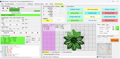
• Host software: GRBL Plotter on the PC — it handles multi-colour jobs by inserting M-commands between layers to trigger the tool change routine.
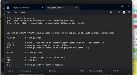
• Workflow: SVG with one layer per colour → GRBL Plotter → streamed to the machine → at each colour boundary, a tool-change macro drops one pen in the dock and picks up the next.
5.4. Application
The demo application is artistic multi-colour plotting — line-art, mandalas, simple diagrams — but the same mechanism can also be used for educational visualisation (drawing graphs from data), lightweight PCB-stencil outlining on paper, and quick print-preview sketches for larger projects. Crucially, because pens are cheap and swappable, we are not locked to one medium: we can load in fine-liners, markers, gel pens, and even thin brushes with minimal firmware changes.
6. Fabrication — 3D printing the parts
The full set of 3D-printed parts came out to roughly 28 pieces — brackets, bearing blocks, motor mounts, idler pulleys, the pen holder, and the tool-changer dock. We split printing across three printers to parallelise. Total print time was approximately two days of combined wall-clock time.
|
Part / Component |
Qty |
Notes |
|
X/Y motor mounts |
2 |
PLA, 100% infill |
|
Bearing blocks (LM8UU) |
6 |
PLA, 100% infill |
|
Belt tensioners / idlers |
4 |
PLA, 100% infill |
|
Pen carriage with servo mount |
1 |
PLA, 100% infill |
|
Tool-changer dock with 4 slots |
1 |
PLA, 100% infill |
|
Pen collars (magnetic) |
4 |
PLA, 100% infill |
|
Frame corners and brackets |
8 |
PLA, 100% infill |
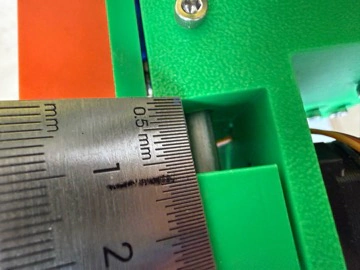
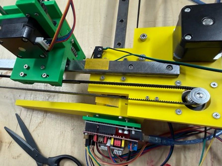
After printing, the green and yellow PLA parts were sorted by subsystem before assembly: frame parts first, then bearing blocks, then carriage and tool-changer parts. This made it easier to check that no mirrored part or duplicate bracket was missing before the rods and belts were installed.
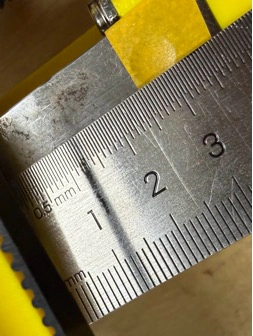
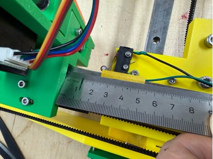
Belt tension and endstop being fitted — ruler used to check that the carriage travel matches the expected work area.
7. Assembly (James + Yaroslav)
James and I did the mechanical assembly together in the lab. We split the work so one person held and aligned while the other drove screws, then swapped — this alone saved us a lot of re-alignment time compared to doing it solo.
1. Built the two side frames first, squared them against a reference plate.
2. Fitted the 8 mm X-axis rods through the bearing blocks, added the GT2 belt loop with idler + motor pulley.
3. Repeated for the Y-axis carriage, then seated the carriage on the X rods.
4. Mounted the pen holder and SG90 servo on the carriage.
5. Installed the tool-changer dock and checked the four pen slots are co-planar with the pen-down Z height.
6. Routed cables through printed cable guides so nothing snags on the belts.
8. Electronics
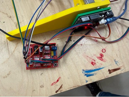
For electronics we kept it boring-on-purpose: Arduino UNO + CNC Shield v3 + A4988 drivers + SG90 servo. The only deviation from the default CNC-shield wiring is that we route the servo signal to the SpnEn (D11) pin, which is what grbl-servo re-purposes for the pen lift. Steppers get 24 V from an external PSU; the UNO is USB-powered during tuning.
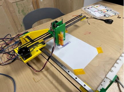
Before wiring, we checked the green/yellow frame mechanically: the frame had to sit square on the bench, the pen carriage had to slide without binding, and the tool-changer dock had to stay aligned with the carriage path. These checks were important because electronics debugging is much harder if the mechanical movement is already unreliable.
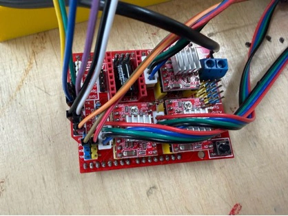
Wiring diagram of the Coloured Plotter electronics (Arduino UNO + CNC Shield + servo).
The real wiring was kept visible during debugging: Arduino UNO, CNC shield, A4988 drivers with heatsinks, servo cable, endstop cables, and motor wires were all routed so we could still probe them with a multimeter and change connections without disassembling the whole machine.
|
VREF tuning For the A4988 drivers we measured VREF on the trim-pot with a multimeter and set it to about 0.8 V. Rule-of-thumb: Imax = VREF × 2.5 (for the standard A4988 module). Our NEMA 17 motors are rated at 1.7 A, but we aim for ~1.0–1.2 A to keep them cool on a long plot — steppers heat up surprisingly fast on continuous XY motion. |
9. Firmware — GRBL with servo support (Part 2)
Plain GRBL only knows a spindle, not a servo. To get a pen lift we used the community-maintained fork cprezzi/grbl-servo, which re-uses GRBL's spindle-PWM output as a servo-PWM output. The flashing procedure is identical to mainline GRBL: delete the old library, add the grbl-servo ZIP, open File → Examples → grbl → grblUpload, upload.
9.1. config.h modifications
Before flashing, there are a few constants in config.h that need editing so the firmware knows we are running a plotter, not a mill.

• VARIABLE_SPINDLE must be enabled (it is by default).
• SPINDLE_PWM_MIN_VALUE / SPINDLE_PWM_MAX_VALUE set the servo pulse range — tune these once the pen holder is mounted so pen-up actually lifts the tip clear of the paper.
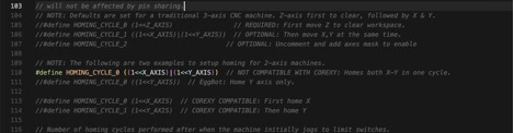
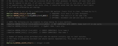
• HOMING_CYCLE_0 / HOMING_CYCLE_1 define homing order. For a plotter we home X first, then Y — the opposite of some mills.
Because the screenshots can be hard to read after web compression, the important firmware edits are also embedded here. These lines are the values I checked in config.h before flashing grbl-servo:
// Enable the PWM output that grbl-servo uses for pen up/down control.
#define VARIABLE_SPINDLE

// Servo/PWM range used by M3/M5 commands.
// These values are tuned after the pen holder is mounted.
#define SPINDLE_PWM_MIN_VALUE 0
#define SPINDLE_PWM_MAX_VALUE 1000

// Home X first, then Y, which is easier for this plotter layout.
#define HOMING_CYCLE_0 (1<<X_AXIS)
#define HOMING_CYCLE_1 (1<<Y_AXIS)
In simple words, this change makes the firmware treat the spindle PWM pin like a servo control pin. Then the machine can use normal G-code commands to lift or lower the pen, while the homing cycle keeps the carriage movement predictable before each drawing.
9.2. Speed parameters
Because NEMA 17s are much more capable than 28BYJ-48s, our speeds can be an order of magnitude higher than the warm-up plotter.
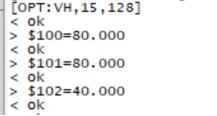
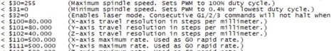
These were the key GRBL settings used for the larger plotter:
$100=80    ; X-axis steps per mm
$101=80    ; Y-axis steps per mm
$110=6000  ; X-axis maximum speed in mm/min
$111=6000  ; Y-axis maximum speed in mm/min
$120=500   ; X-axis acceleration
$121=500   ; Y-axis acceleration
$30=1000   ; maximum PWM value for servo / pen control
The main idea is that $100 and $101 control drawing scale, while $110/$111 and $120/$121 control how fast and how sharply the machine moves. If the drawing is too large or too small, I adjust steps/mm. If the pen skips or the belts shake, I reduce speed or acceleration.
|
Part / Component |
Qty |
Notes |
|
$100 / $101 (steps/mm) |
80 / 80 |
16 × micro-stepping, GT2 × 20-tooth pulley |
|
$110 / $111 (max rate, mm/min) |
6000 / 6000 |
Plenty of headroom; we usually plot at 3000–4000 |
|
$120 / $121 (accel, mm/s²) |
500 / 500 |
Smooth enough that pens do not skip |
|
$30 (max spindle / servo PWM) |
1000 |
Full range for pen-up/pen-down |
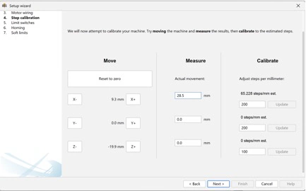
10. Calibration and first manual test (fulfils Part 1, criterion 2)
Before any G-code file ran, we operated the machine manually through UGS — jogging each axis, firing the servo by hand, and measuring actual travel vs. commanded travel. The first pass had X off by about 4 % because I had the wrong number of teeth in my step calculation; one change to $100 fixed it. The Y axis was already correct.
7. Homing — run $H, watch each axis approach its endstop, pull-off, and re-approach slowly.
8. Jog a known distance — command G91 G0 X100 F2000, measure actual travel, adjust $100 by ratio.
9. Servo tune — issue M3 S500 / M5 and watch the pen lift. Adjust SPINDLE_PWM_MIN/MAX until travel is clean.
10. Square test — draw a 50 × 50 mm square, measure with calipers. Ours came out 49.8 × 50.1 mm — acceptable.
11. Circle test — draws a 40 mm circle. Look for corners or flats — they indicate an axis is skipping.

The square and circle calibration drawings were used as measurement tools, not only as a demo. Straight edges showed whether X/Y scaling was right, and the circle made backlash or skipped steps more visible.
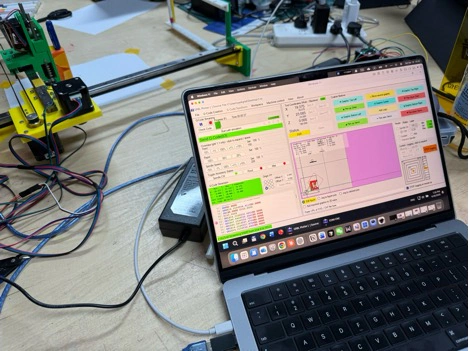
GRBL Plotter showing the calibration job loaded and ready to send.
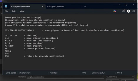
11. Automation — how the tool changer works
The tool-change routine is what makes the Coloured Plotter count as a "machine" for Part 2 rather than just a manually-operated pen plotter. The G-code flow for a four-colour drawing looks like this:
12. Pen 1 is already docked at slot A. Machine homes, then drives to slot A, descends slightly, engages magnetic collar — pen is picked up.
13. All layer-1 (colour 1) paths are streamed — normal XY motion with M3/M5 for pen-down/pen-up.
14. When layer 1 finishes, the host software inserts a tool-change macro: drive to slot A, release pen (Z down, release collar), drive to slot B, pick up pen 2.
15. Layer-2 (colour 2) paths are streamed.
16. Repeat for slots C and D. Final step returns the last pen to its dock and parks the carriage.
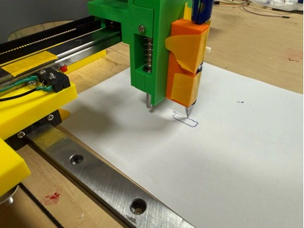
For the tool-change test, we watched the carriage approach the dock slowly, release one pen, move to the next slot, and pick up another pen. This was the most sensitive mechanical part of the machine because a very small error in dock height or collar tolerance could make the pen miss the holder.
What can go wrong here: if the magnetic collar isn't perfectly aligned with the pen holder, you get either a failed pick-up (pen stays docked) or a dropped pen (pen leaves a streak across the page). We spent an afternoon re-printing the collar at 0.1 mm tighter tolerance before it worked reliably.
12. Results & demo
The final Coloured Plotter runs a four-pen multi-layer SVG end-to-end without operator intervention. The mini warm-up plotter still sits on the shelf as a teaching piece — it is slow, tiny, and loud, but it was the best way to understand the whole pipeline before committing to the bigger build.
The final result was evaluated by looking at the finished multi-colour drawing, the repeatability of the pen position after each layer, and whether the machine could complete the run without manual intervention. The final video at the top of this page shows the machine running as the group demo.
13. My individual contribution
Because this is a group project, this section separates my own contribution from the full group work above. Here is specifically what I did, so it is unambiguous for the evaluator.
• Mini CNC warm-up (100% solo): sourced / printed the Thingiverse parts, assembled the mechanics, wired the Arduino Nano + CNC shield, flashed mainline GRBL, configured $$ settings, set up UGS, tested JSCut, produced the first working drawings.
• Coloured Plotter electronics: chose the A4988 + CNC-shield topology, measured VREF, wired the servo to the SpnEn pin, flashed grbl-servo, tuned the pen-up/pen-down PWM.
• Coloured Plotter mechanical assembly (with James): frame squaring, rod + bearing installation, belt routing, pen carriage mounting, tool-dock alignment.
• Calibration: steps/mm tuning, square + circle tests, first multi-colour test drawing.
• Documentation: this page, plus photographs and raw notes used to build the final machine story.
14. Challenges and lessons learned
• GRBL library import trap: the Arduino IDE wants the grbl/ sub-folder, not the repository root. If you get no $$ output on the Serial Monitor, you almost certainly imported the wrong folder.
• Stepper choice matters: 28BYJ-48 steppers are fine for a teaching demo, but they make a real plotter painfully slow. On the Coloured Plotter we jumped straight to NEMA 17s and feed rates 10× higher.
• Servo-branch vs. mainline: we initially flashed mainline GRBL on the Coloured Plotter and wondered why the pen wouldn't lift. grbl-servo is mandatory for any pen-plotter build.
• Tool changer tolerances: the magnetic pen collar is the trickiest single part. Print it at high resolution and be prepared to re-tune the Z pick-up height.
• Lubrication: the warm-up plotter taught us to lubricate rods on day one. The Coloured Plotter got a light oil film on rods and bearings before the first power-on.
15. Reference
15.1. Files for download
|
Project media files in this repository • Final group slide — 1927.PNG. • Final group video — 1916_8mb.MP4. • Process photos and screenshots are stored in the Week 12 image folder and embedded throughout this documentation. 3D CAD files (STEP) • Motor cap — motorcap(1).step. • Wire-holder gate — wireholder_gate(1).step. • Wire-holder joint 1 — wireholder_joint_1(1).step. • Wire-holder joint 2 — wireholder_joint_2(1).step. • Wire-holder joint 3 — wireholder_joint3(1).step. |
15.2. Reference links
• Mini CNC plotter 3D-printed parts — thingiverse.com/thing:4579436
• GRBL for 28BYJ-48 steppers — github.com/TGit-Tech/GRBL-28byj-48
• Mainline GRBL — github.com/gnea/grbl
• grbl-servo branch — github.com/cprezzi/grbl-servo
• Coloured Plotter reference — HowToMechatronics — DIY Pen Plotter with Automatic Tool Changer
• Winnie Sun's individual Week 12 page — fabacademy.org/2026/labs/formshop/students/winnie-sun/weekly/12%20Mechanical%20design
• Zequan Lin's individual Week 12 page — fabacademy.org/2026/labs/formshop/students/zequan-lin/weekly/12%20Mechanical%20design
• Warm-up simple Arduino Mini CNC Plotter — PCBWay article
• Universal G-code Sender — winder.github.io/ugs_website
• JSCut — jscut.org
• Assignment brief — fabacademy.org/2026/nueval/mechanical_design,_machine_design
16. Reflection
This was a hard week because the machine itself, Universal G-code Sender, GRBL, and the other software tools all have many small details that matter. I had to spend time understanding how G-code is written, how to read commands like movement, homing, and pen up/down, and how those commands become real motion on the machine. In the end we successfully plotted a black-and-white image, which showed that the axes, firmware, and drawing workflow were working. The colour-changing part is still on the way: the machine can move and imitate changing markers, but I did not fully test real marker changing yet because of the time limitation.