Week 09 — Input Devices / Sensor Testing with My Custom Board
Group assignment
- Probe an input device's analog levels and digital signals (using at least a multimeter and an oscilloscope).
- Document the work on the group page and reflect on individual learnings.
- Group assignment reference: this group work was documented by my classmate Yongfeng. See Yongfeng's Input Devices group assignment page.
Individual assignment
- Measure something: add a sensor to a microcontroller board that you designed and read it.
Documentation
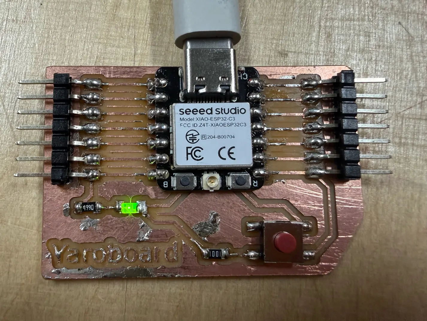
During Week 8 Electronic Design, I designed and fabricated my own board based on the Seeed Studio XIAO ESP32-C3 microcontroller. After milling, cleaning, and soldering the microcontroller and other components, the final board looked like this:
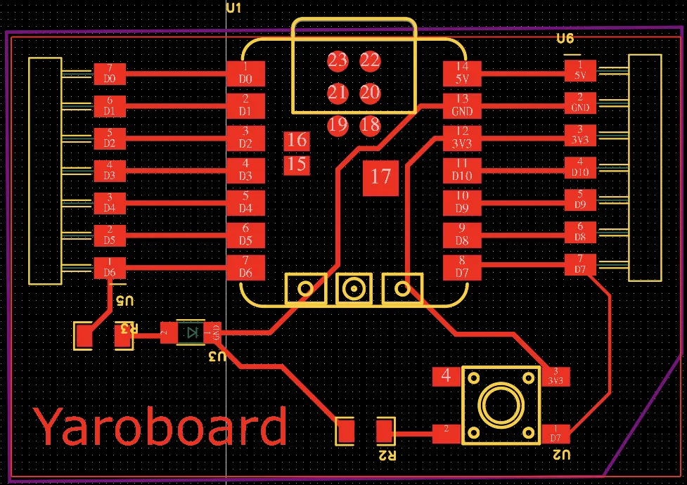
The circuit diagram is shown below:
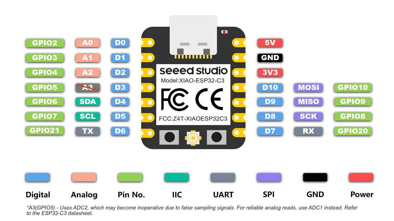
I also used the pinout diagram of the XIAO ESP32-C3 to understand how to connect and test the different sensors and actuators.
For this week, I tested several input devices and checked how they interacted with the LED on my custom board.
Working with Pins on the XIAO ESP32-C3
At the beginning, I had a problem addressing the pins in Arduino code. I first tried using numeric values such as
1, 2, and 6, but this did not work as expected. After checking
documentation and
debugging tutorials, I understood that in Arduino IDE for the XIAO ESP32-C3, pins should be addressed with names
such as
D6, D7, and D10.
This solved the issue, and after that my LED and sensors started working correctly.
Reference materials
1. Embedded LED Blink
My first test was a simple LED blinking program using the LED connected to pin D6 on my custom board.
Code
void setup() {          // the setup function runs once when you press reset or power the board
  pinMode(D6, OUTPUT);   // initialize digital pin D6 as an output.
}

// the loop function runs over and over again forever
void loop() {
  digitalWrite(D6, HIGH);  // turn the LED on
  delay(1000);             // wait for a second
  digitalWrite(D6, LOW);   // turn the LED off
  delay(1000);             // wait for a second
}
Result
- The board was powered correctly.
- The microcontroller was programmed correctly.
- The LED circuit was working.
Video - Ebbedded LED blinking test
I also tested the same logic with an external LED. In that case, I only needed to change the pin number from
D6 to D10, depending on where the external LED was connected.
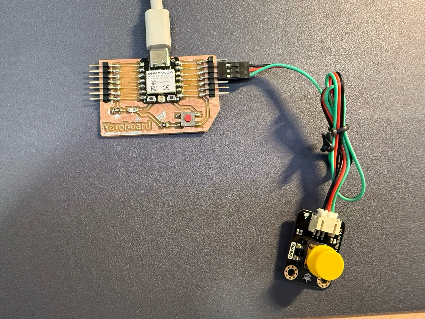
2. Embedded Button and LED
Next, I tested the onboard button together with the LED. Every button press toggled the LED state.
How the button works
A push button is a digital input device with only two states: pressed and not pressed. I used
INPUT_PULLUP, so the pin reads HIGH when idle and LOW when pressed to
ground.
Code
const int ledPin = D6;
const int buttonPin = D7;

bool ledState = false;
bool lastButtonState = HIGH;
bool currentButtonState = HIGH;

void setup() {
  pinMode(ledPin, OUTPUT);
  pinMode(buttonPin, INPUT_PULLUP);  // button to GND
  digitalWrite(ledPin, LOW);
}

void loop() {
  currentButtonState = digitalRead(buttonPin);

  // detect button press (HIGH -> LOW)
  if (lastButtonState == HIGH && currentButtonState == LOW) {
    ledState = !ledState;
    digitalWrite(ledPin, ledState);
    delay(200);   // simple debounce
  }

  lastButtonState = currentButtonState;
}
Result
The embedded button successfully toggled the LED on and off.
Video - Embedded button and LED test
The same logic also worked for an external button by changing to const int buttonPin = D10;.
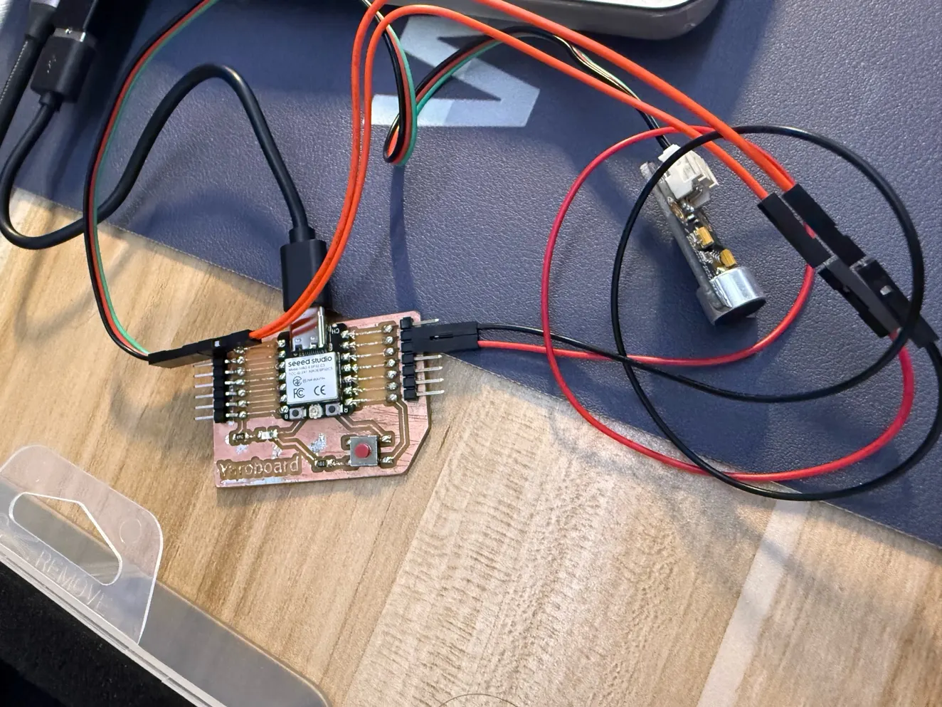
3. External Vibration Sensor
After testing a basic digital button, I moved on to a vibration sensor.
How the vibration sensor works
A vibration sensor is typically a digital input. In my test, the sensor output became LOW when
vibration was detected, so the logic had to match this behavior. I just need to modify previous code to match new
sensor requirements.
LOW= vibration detectedHIGH= no vibration
Code
const int ledPin = D6;
const int vibrationPin = D10;

void setup() {
  pinMode(ledPin, OUTPUT);
  pinMode(vibrationPin, INPUT_PULLUP);
  digitalWrite(ledPin, LOW);
}

void loop() {
  int vibrationState = digitalRead(vibrationPin);

  if (vibrationState == LOW) {    // shaking detected
    digitalWrite(ledPin, HIGH);
    delay(50);
    digitalWrite(ledPin, LOW);
    delay(50);
  } else {
    digitalWrite(ledPin, LOW);
  }
}
Result
When the sensor was shaken, the LED blinked quickly. With no vibration, the LED stayed off.
Video - External vibration sensor test
4. External Analog Sound Sensor
Then I tested an analog sound sensor.
How the sound sensor works
Unlike the vibration sensor, the sound sensor returns an analog value based on sound intensity. I moved the output
to
an analog pin and used analogRead() instead of digitalRead(). I connected it to
A0. The code is similar to his previous sensor, but I need to rename the pins, and here is another
variable "threshold" which I can change for sensitivity.
Code
const int ledPin = D6;
const int soundPin = A0;      // sound sensor connected to A0
const int threshold = 500;    // adjust this value after testing

void setup() {
  pinMode(ledPin, OUTPUT);
  digitalWrite(ledPin, LOW);
  Serial.begin(115200);
}

void loop() {
  int soundValue = analogRead(soundPin);
  Serial.println(soundValue);

  if (soundValue > threshold) {
    digitalWrite(ledPin, HIGH);
    delay(50);
    digitalWrite(ledPin, LOW);
    delay(50);
  } else {
    digitalWrite(ledPin, LOW);
  }
}
Result
When sound intensity was above the threshold, the LED blinked. Below the threshold, it stayed off. This helped me understand the practical difference between digital and analog sensor behavior.
5. External Analog Ambient Light Sensor
I also tested an ambient light sensor as another analog input device.
How the ambient light sensor works
The sensor measures light intensity as a continuous analog signal. I used the same workflow as the sound sensor:
read with analogRead(), compare to a threshold, and react when crossing the threshold.
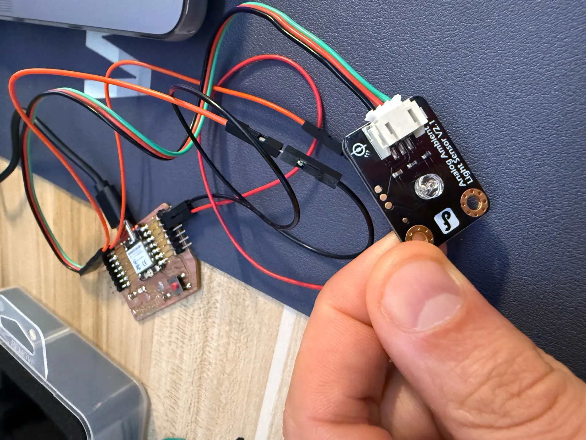
At first, the threshold was too low and the LED blinked too easily, so I increased it to
const int threshold = 2000;.
Observation
With a higher threshold, the LED remained off under normal room light. When I moved my iPhone camera close to the sensor while recording, the LED started blinking again. This suggests the camera light or IR system affected the reading.
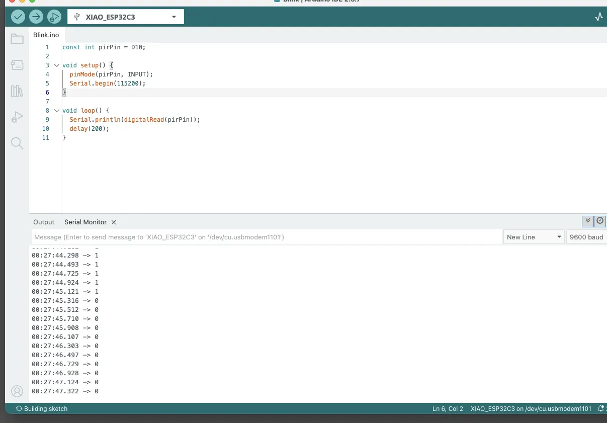
6. PIR Motion Sensor
Next, I tested a PIR motion sensor.
How a PIR sensor works
A PIR (Passive Infrared) sensor detects changes in infrared radiation, not camera-like image motion. It responds to heat-pattern changes, such as a person crossing its field of view.
5VpowerGND- Digital signal on
D10
The sensor also needed a warm-up time of around 10 to 30 seconds before stable output.
I experienced some issues with the initial setup, so to better understand how the sensor was behaving, I used the Serial Monitor to observe its input signal in real time.
In my kit, the PIR sensor is a digital sensor, so I had to reconnect it to a digital input pin instead of using an analog input.
Debugging code using Serial Monitor
const int pirPin = D10;

void setup() {
  pinMode(pirPin, INPUT);
  Serial.begin(115200);
}

void loop() {
  Serial.println(digitalRead(pirPin));
  delay(200);
}
Code for LED blinking on motion
const int ledPin = D6;
const int pirPin = D10;

void setup() {
  pinMode(ledPin, OUTPUT);
  pinMode(pirPin, INPUT);
  digitalWrite(ledPin, LOW);
}

void loop() {
  int motion = digitalRead(pirPin);

  if (motion == HIGH) {
    digitalWrite(ledPin, HIGH);
    delay(60);
    digitalWrite(ledPin, LOW);
    delay(60);
  } else {
    digitalWrite(ledPin, LOW);
  }
}
Result
When motion was detected, the LED blinked rapidly; otherwise it stayed off.
Video - PIR motion sensor test
7. Potentiometer (Rotation Sensor)
Finally, I tested a potentiometer (rotation sensor).
How the potentiometer works
A potentiometer is an analog input. Rotating the knob changes resistance and output voltage, which the MCU reads
as
an analog value. I connected it to A0 and used the reading to control LED blink speed.
Goal
- At minimum position, LED should stay off.
- As the knob rotates, LED should blink faster.
- At maximum position, LED should blink very fast.
Code
const int ledPin = D6;
const int rotationPin = A0;

void setup() {
  pinMode(ledPin, OUTPUT);
  digitalWrite(ledPin, LOW);
  Serial.begin(115200);
}

void loop() {
  int sensorValue = analogRead(rotationPin);

  int level = map(sensorValue, 0, 4095, 0, 10);
  level = constrain(level, 0, 10);

  Serial.print("Value: ");
  Serial.print(sensorValue);
  Serial.print("  Level: ");
  Serial.println(level);

  if (level == 0) {
    digitalWrite(ledPin, LOW);
    delay(30);
    return;
  }

  int blinkDelay = 550 - (level * 50);

  if (blinkDelay < 20) {
    blinkDelay = 20;
  }

  digitalWrite(ledPin, HIGH);
  delay(blinkDelay);
  digitalWrite(ledPin, LOW);
  delay(blinkDelay);
}
Code explanation
This code reads the value from a rotation sensor connected to A0 and uses it to control how fast an
LED on D6 blinks. The sensor value is converted into a level from 0 to 10, and this level is
printed in the Serial Monitor together with the raw sensor reading. If the level is 0, the LED stays off, and if
the level is higher, the LED blinks faster as the sensor value increases.
Result
The potentiometer successfully controlled LED blinking speed, creating around ten visible levels from no blinking to very fast blinking.
Video - Potentiometer-controlled LED blink speed
Reflection
This series of tests helped me better understand the difference between digital and analog input devices.
Digital sensors tested
- Button
- Vibration sensor
- PIR motion sensor
Analog sensors tested
- Sound sensor
- Ambient light sensor
- Potentiometer
What I learned
- How to identify whether a sensor is analog or digital.
- How to connect sensors to appropriate pins.
- How to use
digitalRead()andanalogRead(). - How to debug sensor behavior with Serial Monitor.
- How to control outputs based on different sensor behaviors.