Week 03 - Computer-Controlled Cutting
Group Assignment
- Characterize your laser cutter's focus, power, speed, rate, kerf, and joint clearance.
- Document your work on the group work page and reflect on your individual page about what you learned.
Group assignment reference by my classmate Zequan Lin: https://fabacademy.org/2026/labs/formshop/students/zequan-lin/weekly/03%20Computer-controlled%20cutting/
Individual Assignment
- Cut something on the vinyl cutter.
- Design, cut, and document a parametric construction kit, accounting for laser cutter kerf and assembly.
Learning Outcomes
- Identify and describe the process of using a laser cutter.
- Identify and describe the process of using a vinyl cutter.
- Demonstrate how you made your vinyl cutting design.
- Explain how you created and evaluated the parametric construction kit.
Checklist
- Linked to the group assignment page.
- Explained how you characterized tool joint clearance and kerf.
- Documented how you made your parametric design and construction kit.
- Explained problems and how you fixed them.
- Included design files and photos of finished pieces.
- Included vinyl cutting files and photos of the result.
Documentation
Modular design. Parametric
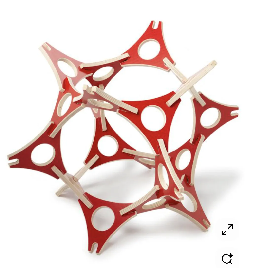
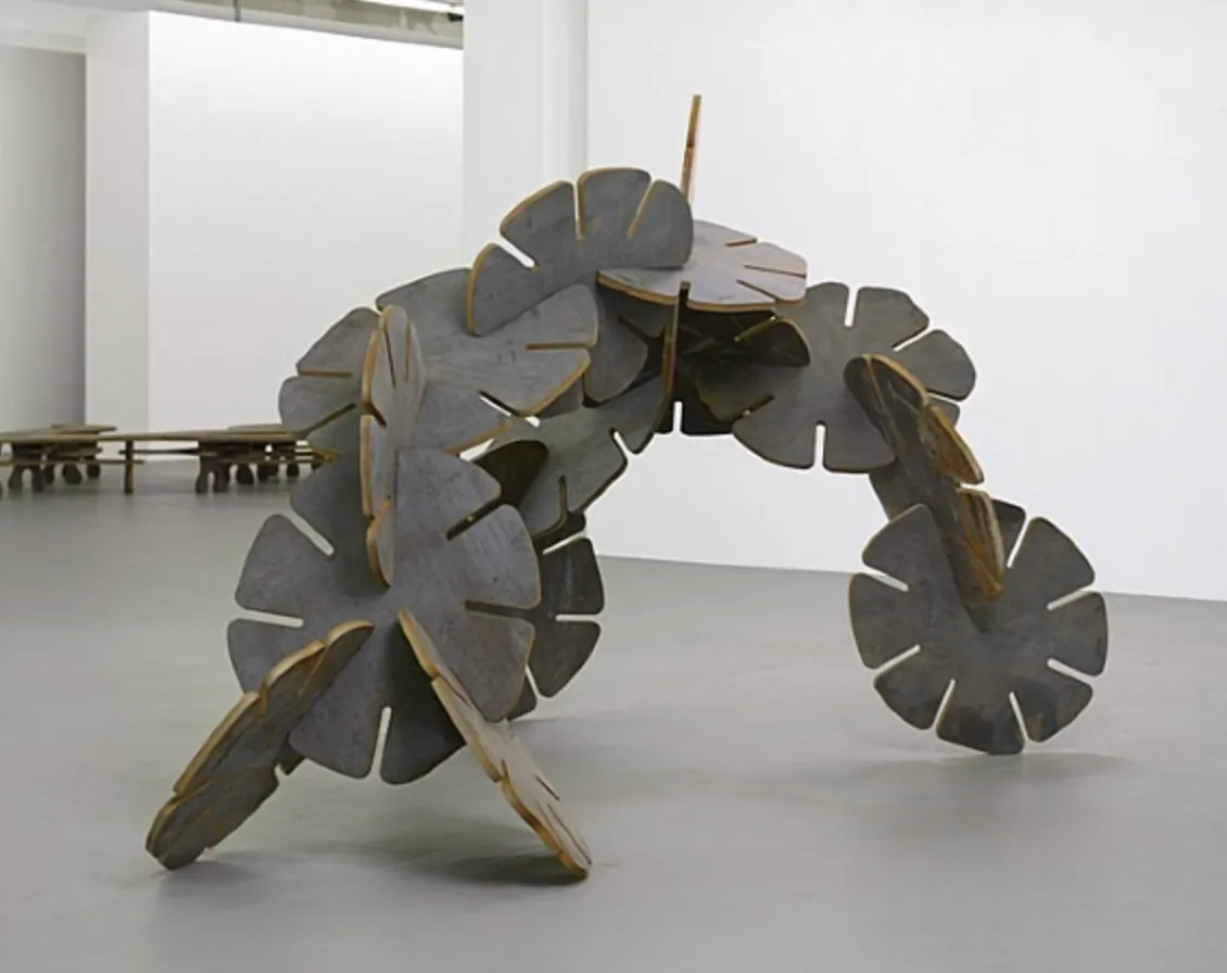
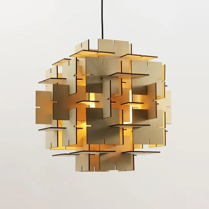
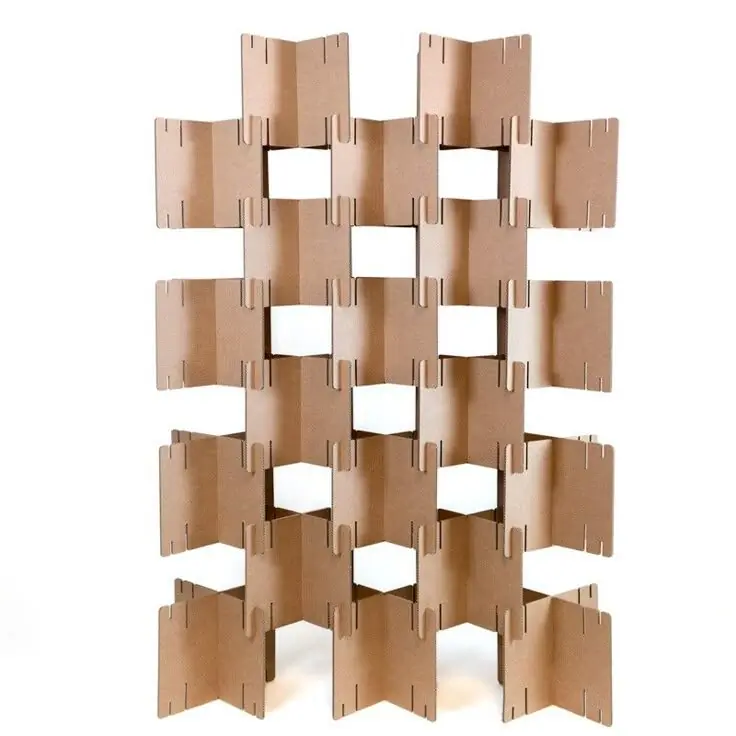
Inspiration.
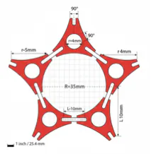
To make the project modular and doable, I searched the internet for some modular components and pattern ideas based on simple shapes. I wanted to make one component that contains many options for assembly.
A YouTube video was also helpful for understanding how to make a parametric model in Fusion: https://www.youtube.com/watch?v=Uel_NmlwdoA
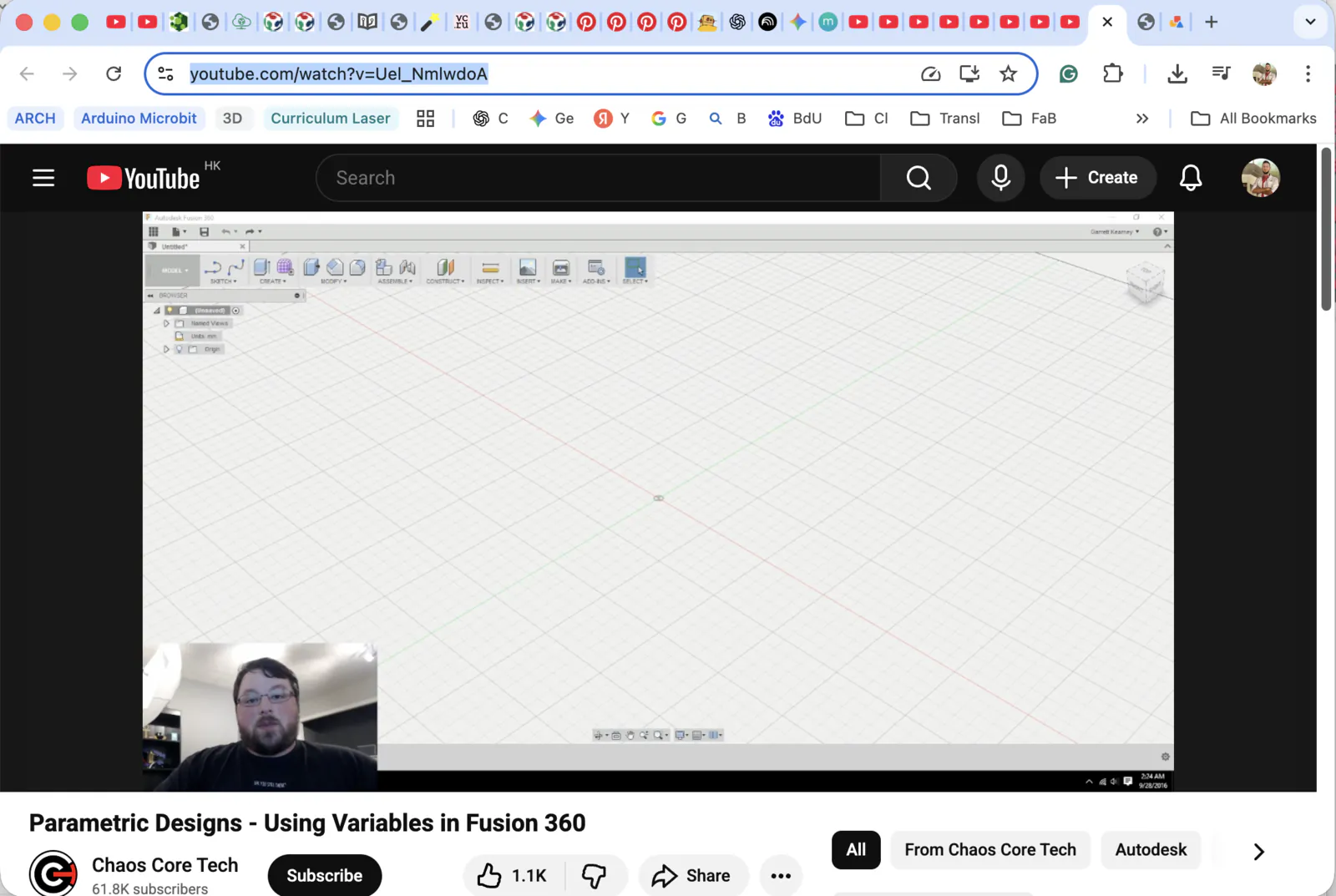
I used this reference as a starting point. I also asked Google Gemini to generate a flat sketch, but it was not correct in dimensions and assembly. Still, it helped me understand what kind of sketch I needed to create.
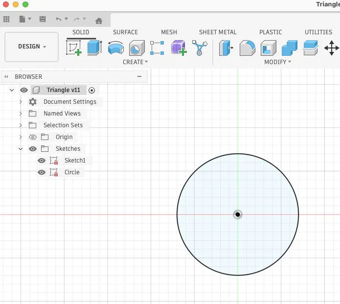
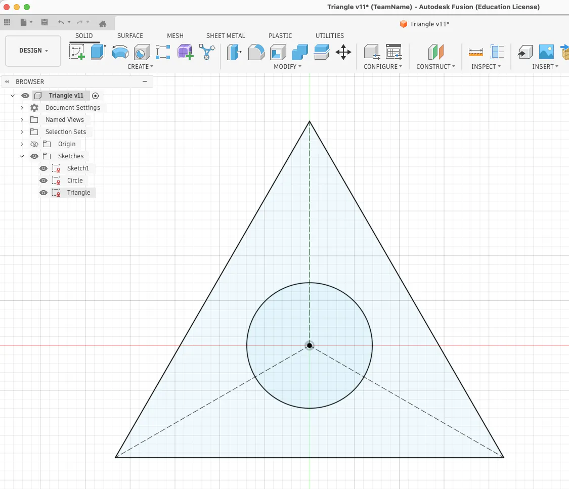
Start from a circle at the origin.
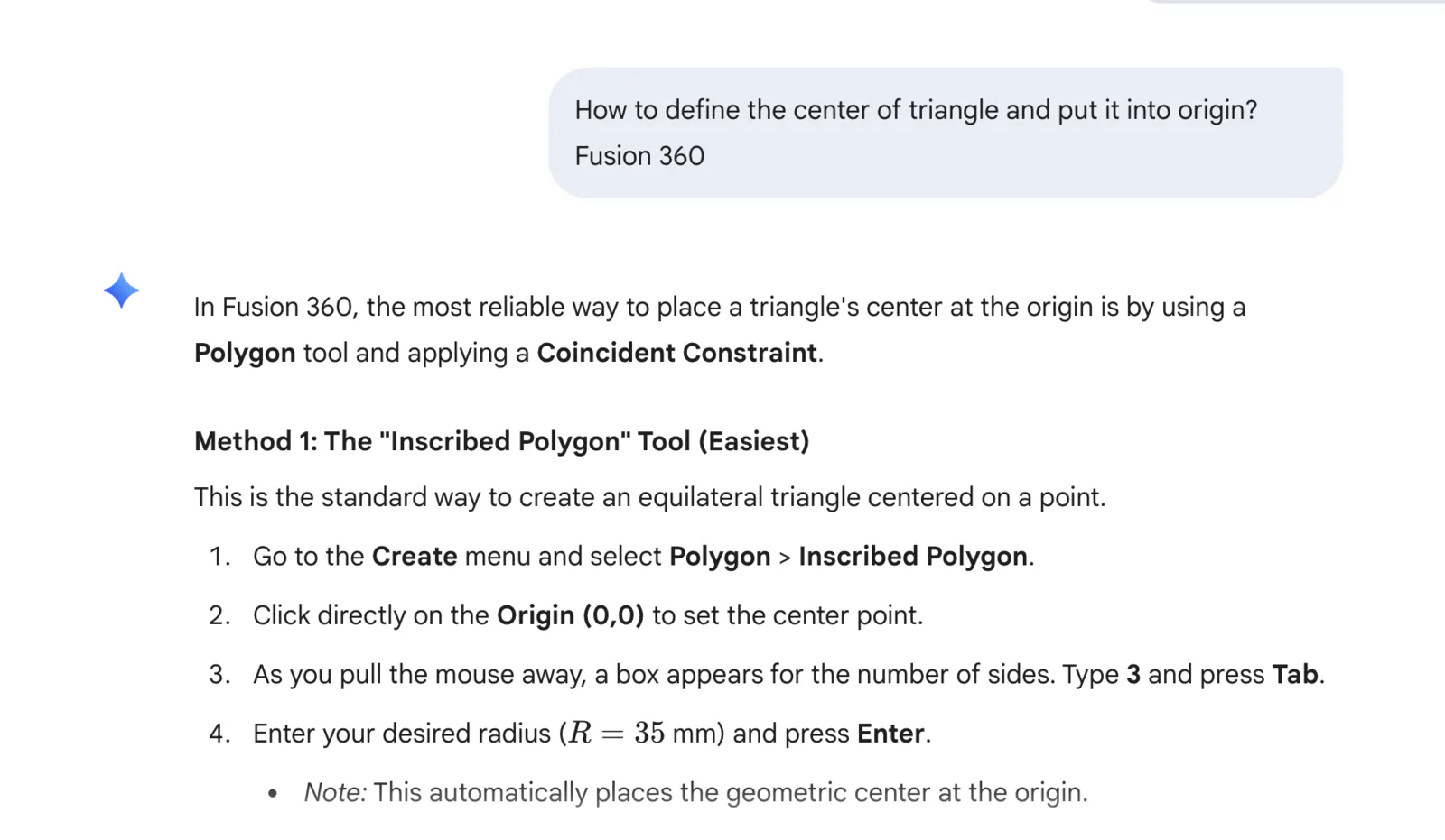
Then I needed to place a triangle in the center. This part was a bit complicated, so I asked Gemini which tool to use and how to define the triangle center.
I also added three construction lines to snap future ovals.
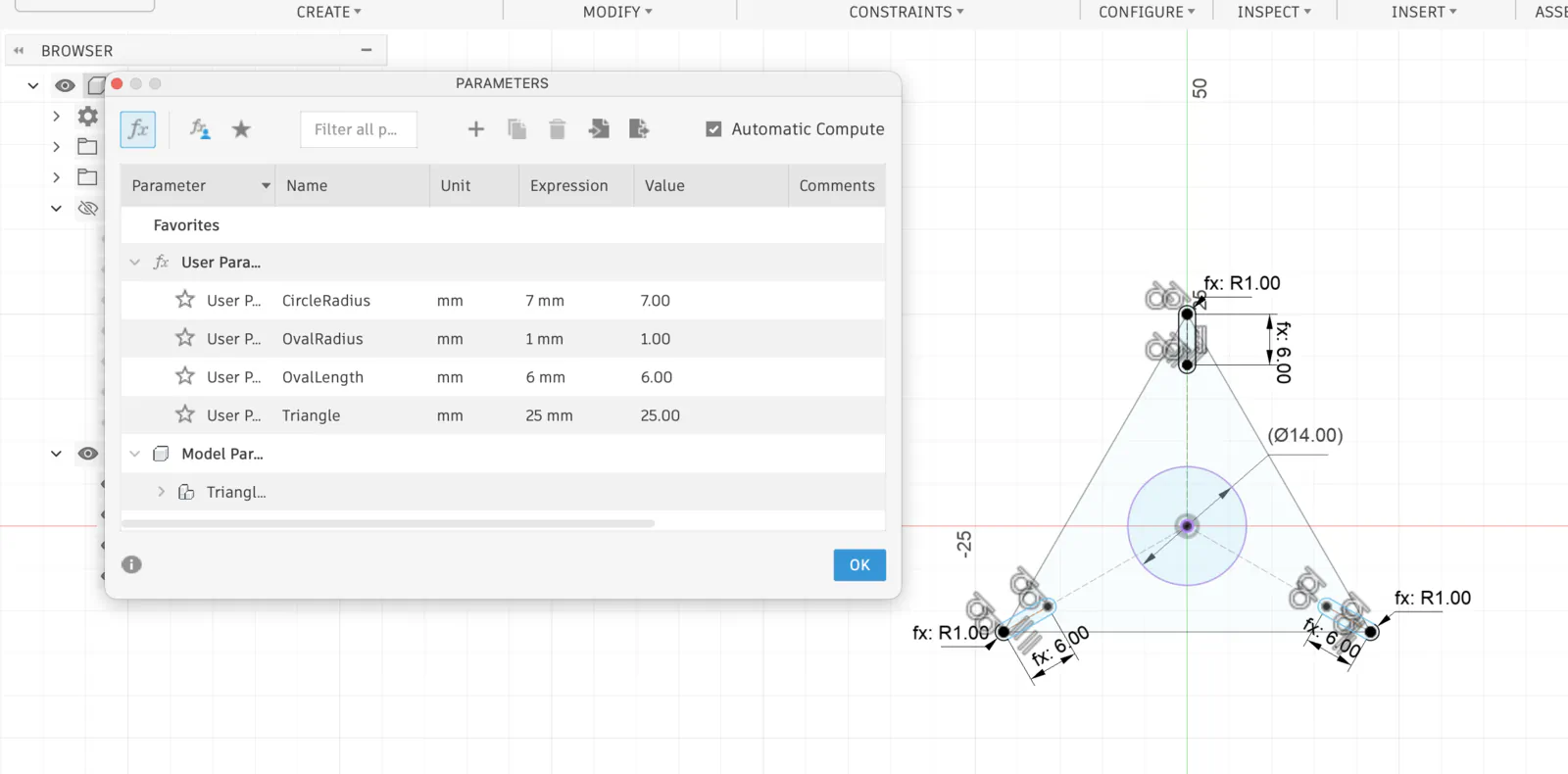
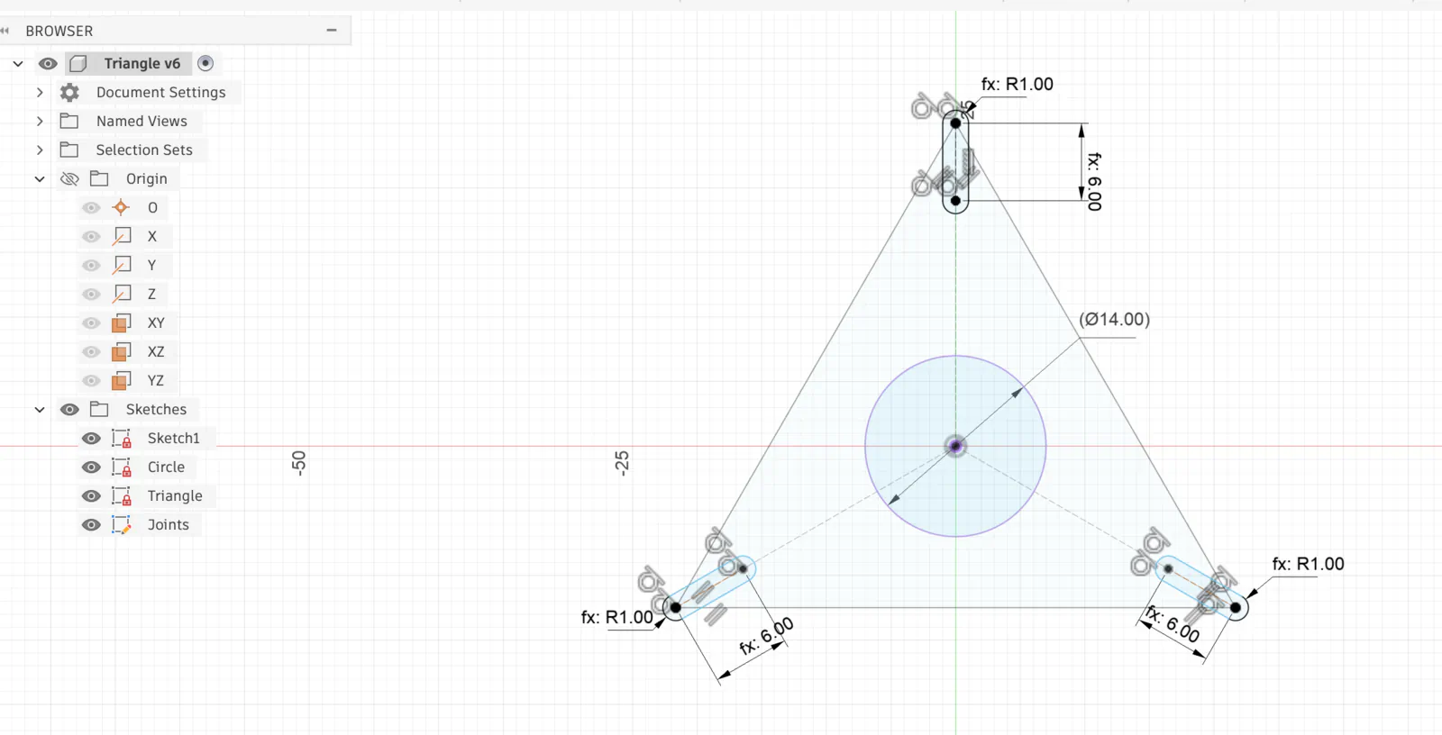
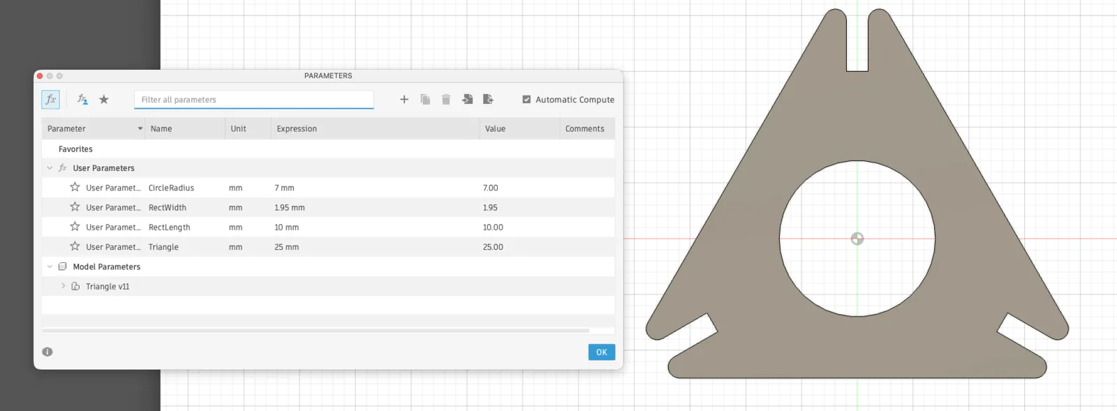
After I made three ellipse shapes, I copied and rotated them by 120 and 240 degrees, snapped them to the construction lines, and defined constraints. Then I created variables and made the sketch fully parametric.
I did not know how to cut in sketch mode, but I knew how to do it in solid mode. I extruded a triangle, extrude-cut ellipses and the middle circle, and then applied a 1 mm fillet on the edges.
Parametric variables work.
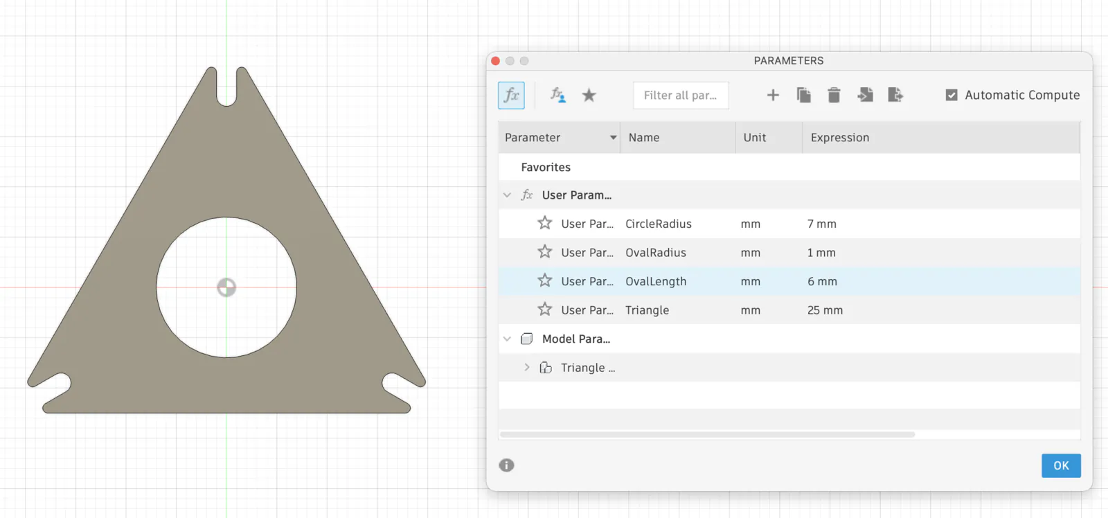
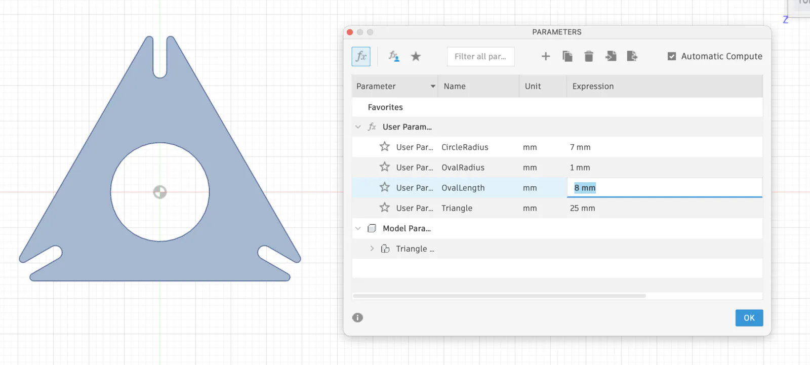
After the test cut, I realized that an oval/circular shape on the joint is not the best solution. It should be changed to a rectangle, and dimensions should be adjusted for kerf.
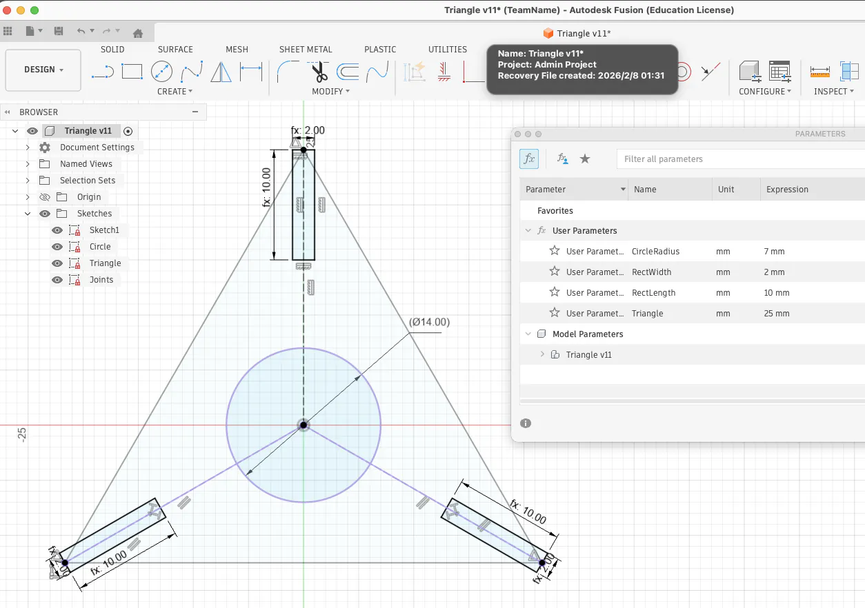
Fully defined parametric sketch.
I prepared a sketch for 2mm, 3mm and 5mm. It still needs testing.
Laser Cutting Test: Real Material Thickness + Parametric Update
Before cutting the final construction kit, I treated laser cutting as a measurement problem, not only a fabrication step. In real life, "3 mm plywood" and "5 mm cardboard" rarely match the label, so I first measured the actual stock with calipers and updated my parametric variables based on what I really had. In my case, the "3 mm plywood" was closer to 2.5 mm, and the "5 mm cardboard" was closer to 3.5 mm. Because the geometry was already fully parametric, I did not redraw anything - I only changed the thickness variables and let the model update automatically.
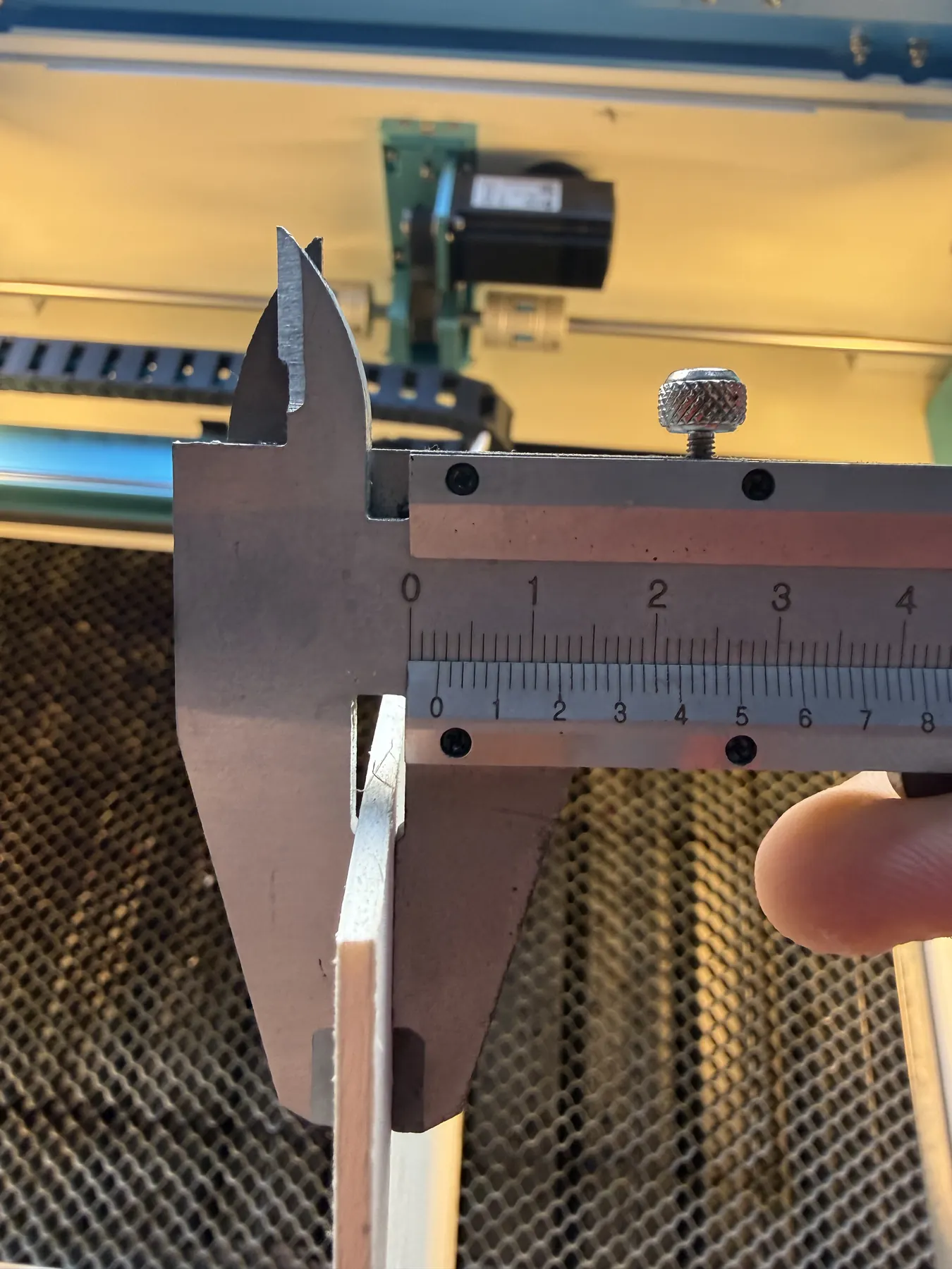
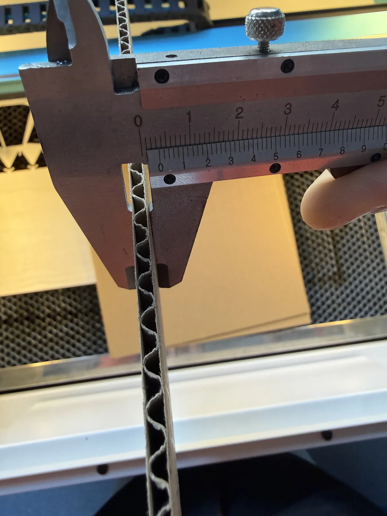
- "3 mm plywood" was approximately 2.5 mm
- "5 mm cardboard" was approximately 3.5 mm
Speed and Power Test for Laser
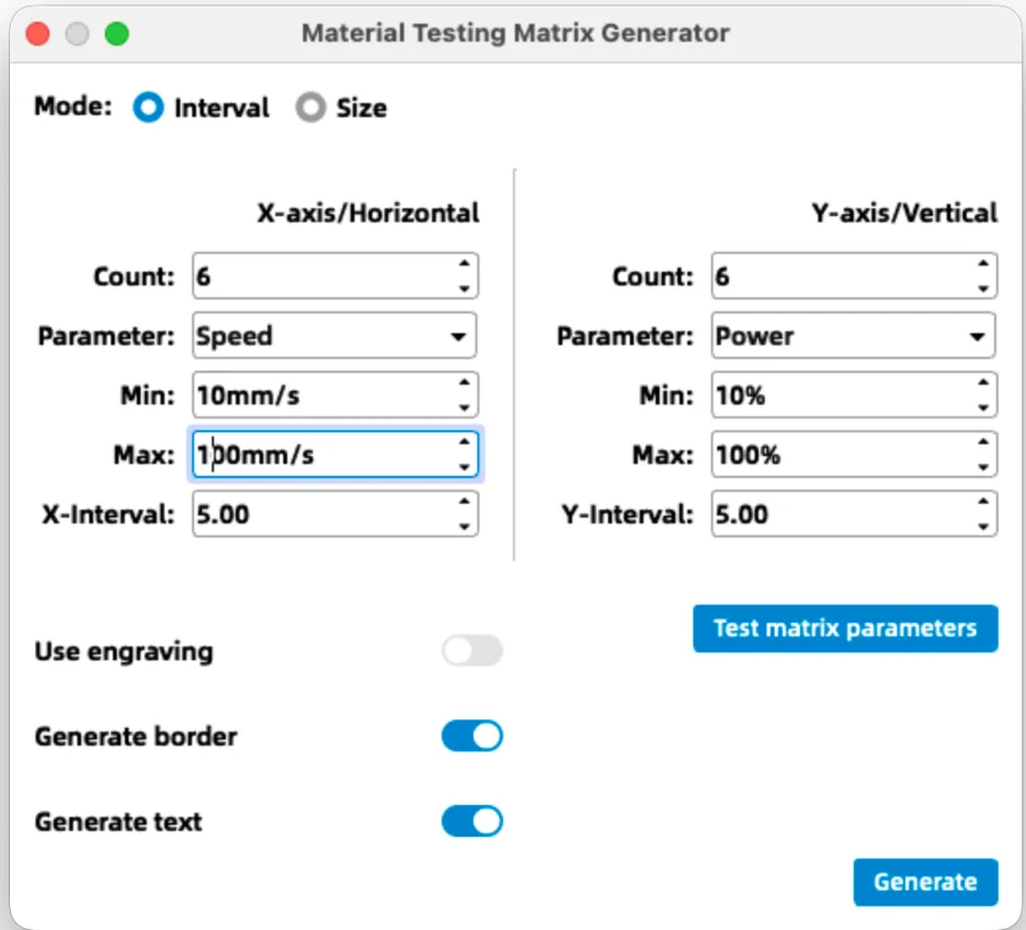
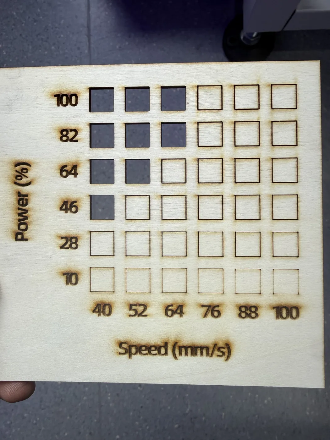
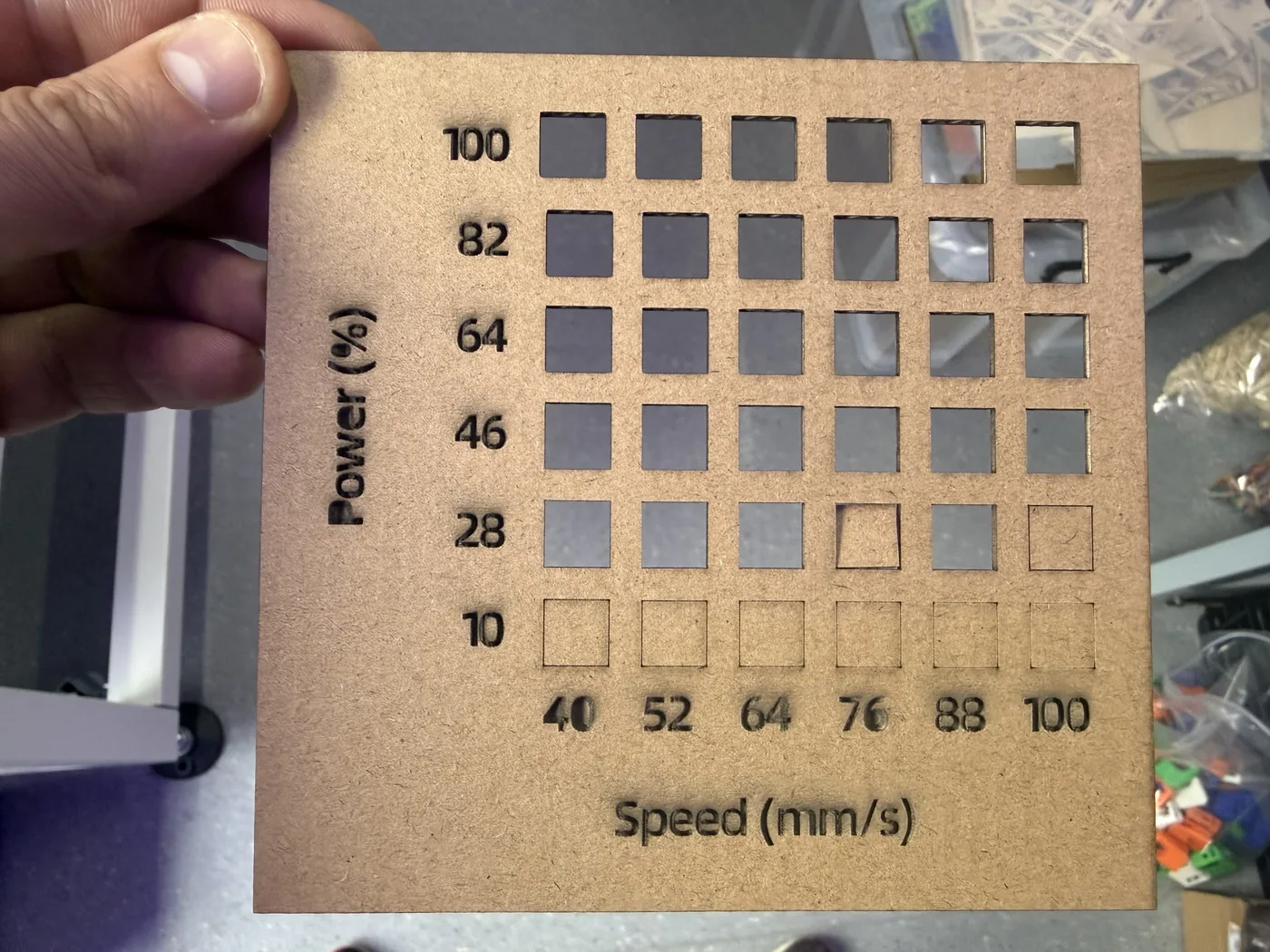
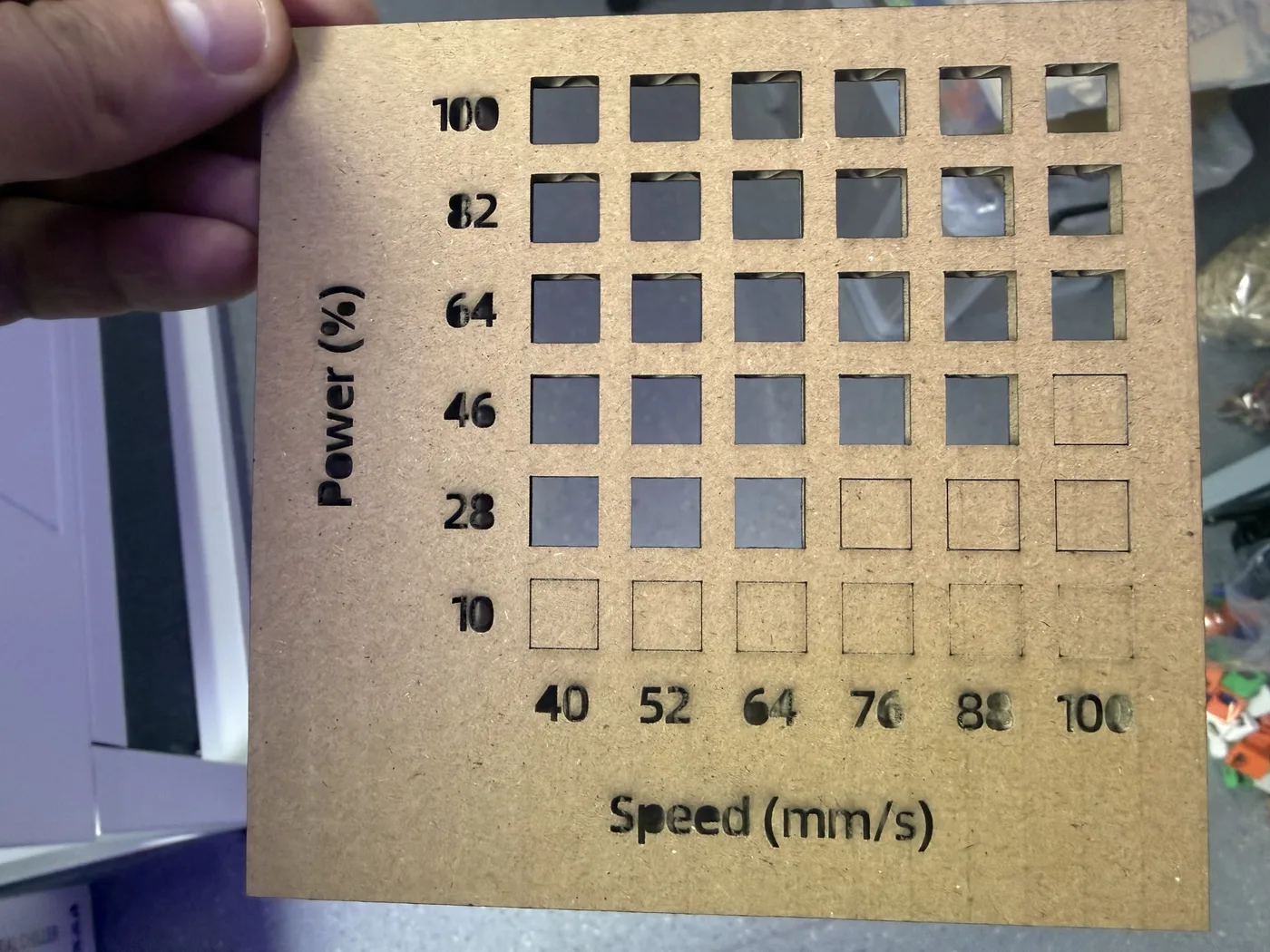
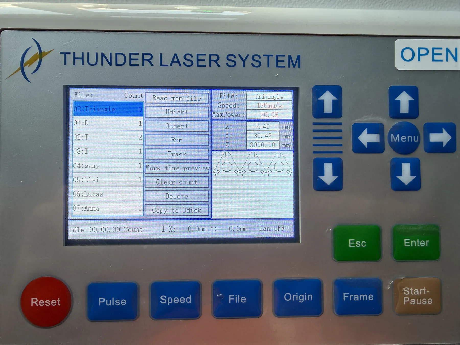
After measuring the real material thickness, I ran a speed and power test using a template from the Laser Maker software. The template can automatically generate a test board, which is useful because it allows me to check different combinations of cutting parameters in one job.
For this test board, I set the speed range from 10 to 100 and the power range from 10 to 100. I did not need engraving for this task because my goal was to find settings for cutting, so I turned the engraving switch off.
After thickness, the next hidden variable is the kerf: the laser removes material along the cut line, so parts do not match the CAD dimensions perfectly. During our group assignment, we tested kerf in the lab by cutting a reference pattern, measuring the real result, and comparing it with designed values. A clear way to describe kerf is the width of material burned away by the beam. Even if you cut on the same vector line, the real edge shifts because the beam has thickness and thermal effect. The xTool kerf explanation is a good plain-language reference and matches what we observe in Fab Academy labs: xTool Academy: Laser Cutting Kerf.
Before applying any compensation, I did a quick research check to confirm the correct way to think about kerf and why offsets matter. The key idea is that kerf is the width of material removed by the laser beam, so the final geometry will shift unless we compensate.
In the lab, I also tested the curve on my 2.5 mm plywood board by designing a 20 mm rectangle. After cutting and measuring the real part, the actual distance was 19.2 mm. That means 0.8 mm of material was lost during the process, which helped me understand more clearly how much the cut can affect the final size.
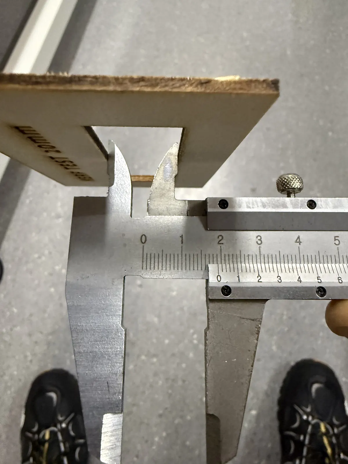
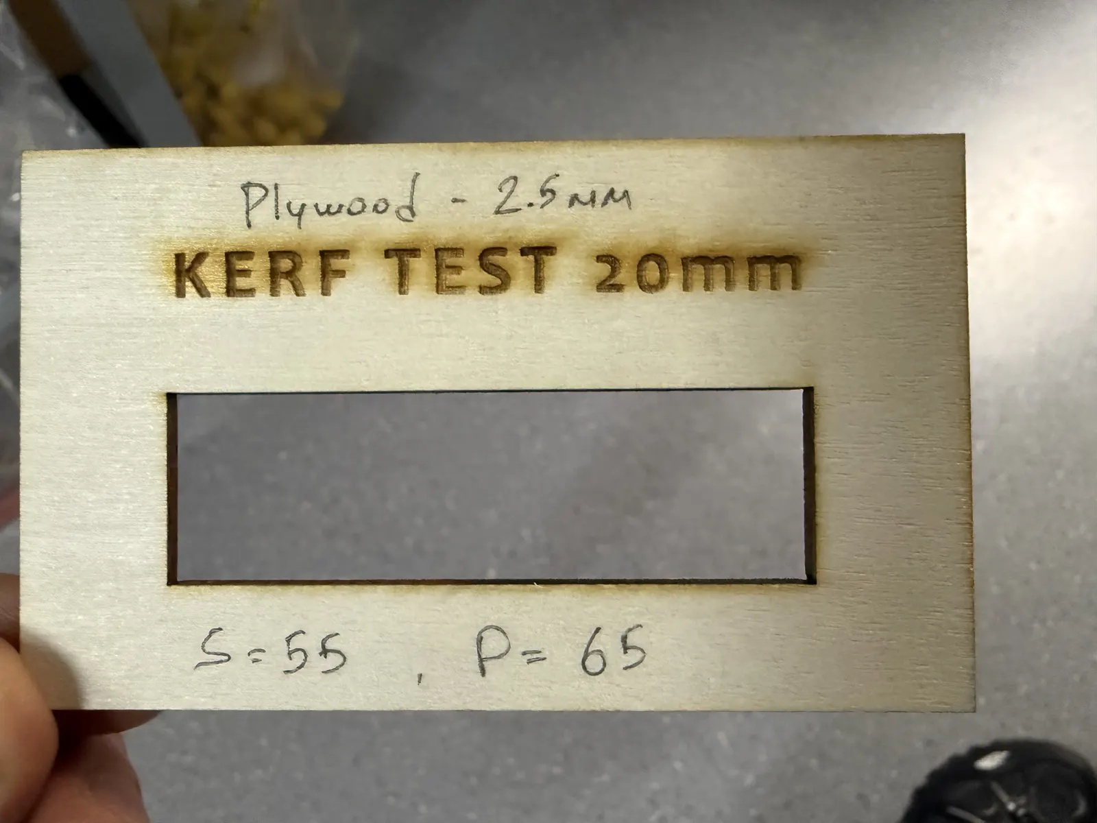
Based on this test, I considered the measured material loss directly in my design. Since the total difference was 0.8 mm, it means the cut affected the geometry by about 0.4 mm on each side. I used this as a practical reference when adjusting the joint dimensions.
For the final joint, I decided not to use the full 0.4 mm value. To make the connection fit better, I made the joint slightly tighter and reduced it by 0.3 mm. This gave me a better press-fit while still accounting for the material removed during cutting.
After defining the rule above, we validated the kerf value through measurement during our group assignment (test pattern → cut → measure → calculate). I used that group-measured kerf result as the reference input for my offset decision. Group reference (Week 03 kerf test documentation).
However, I consider this a good shortcut only when material batch and machine conditions are basically the same. If I switch to a different batch of wood, different thickness, acrylic, or a different laser machine, I will repeat a dedicated kerf test. Next time I will also use the DoyoLab kerf-check tool, because it can speed up workflow by calculating kerf from measurements and generating an SVG test file: DoyoLab Kerf Check Tool.
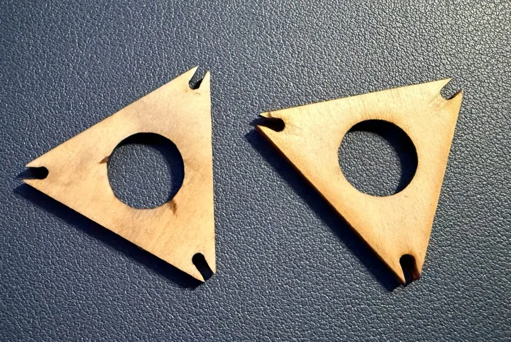
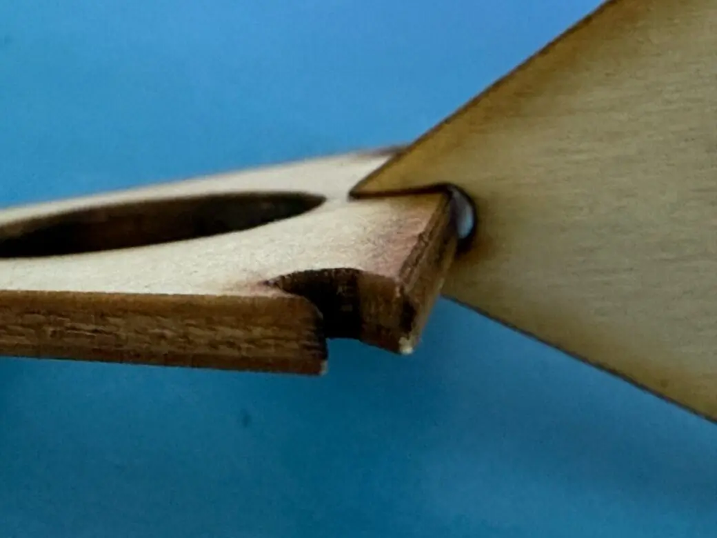
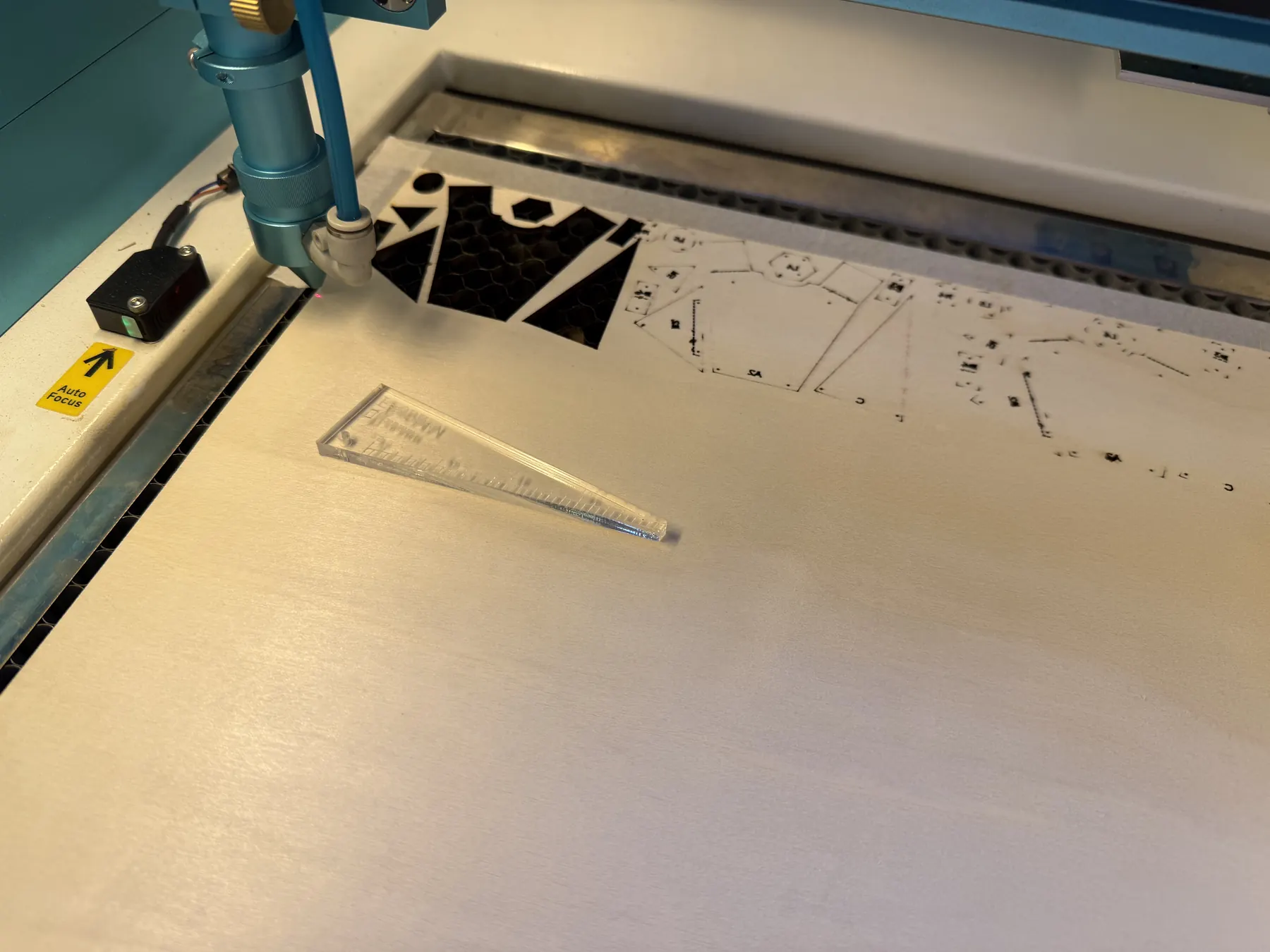
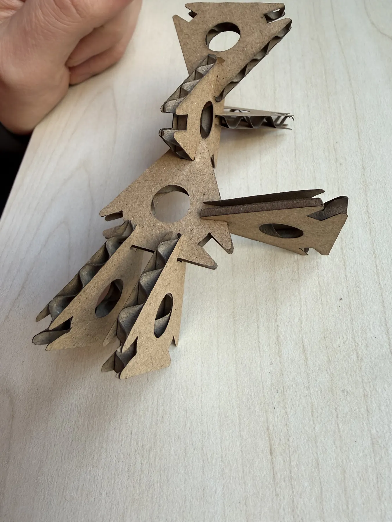
After updating thickness variables and adding kerf compensation, I still ran a small test cut first to validate joint behavior. Only after the test piece confirmed a stable press-fit did I proceed to cut the full set.
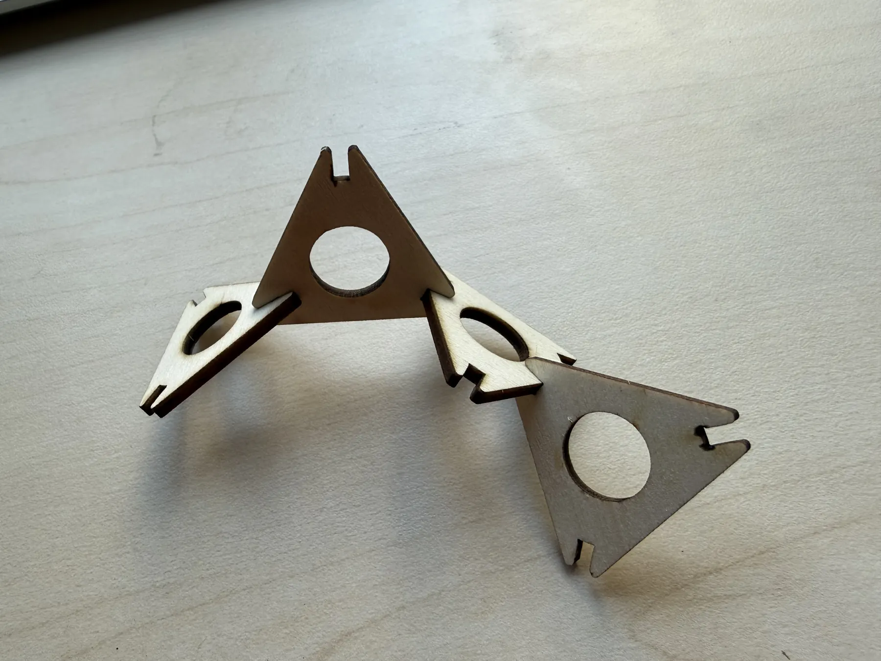
The final result was successful: the joints account for material variation/tolerance, and the parts are strong and stable. They slide in and out smoothly without wobbling, and both the cardboard and plywood versions hold firmly.
- 2.5 mm plywood: Speed 60, Power 80
- 3.5 mm cardboard: Speed 100, Power 50
Laser parameters:
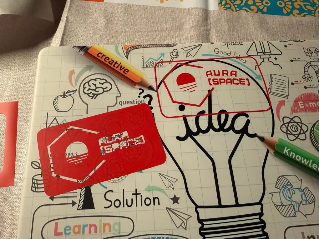
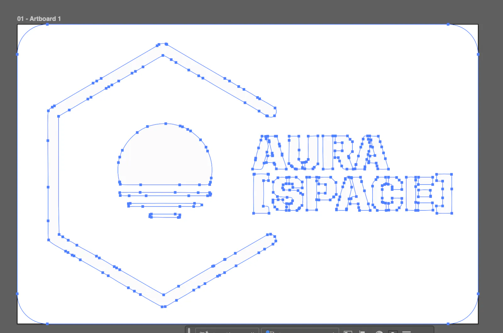
Logo Design and Vinyl Cutter
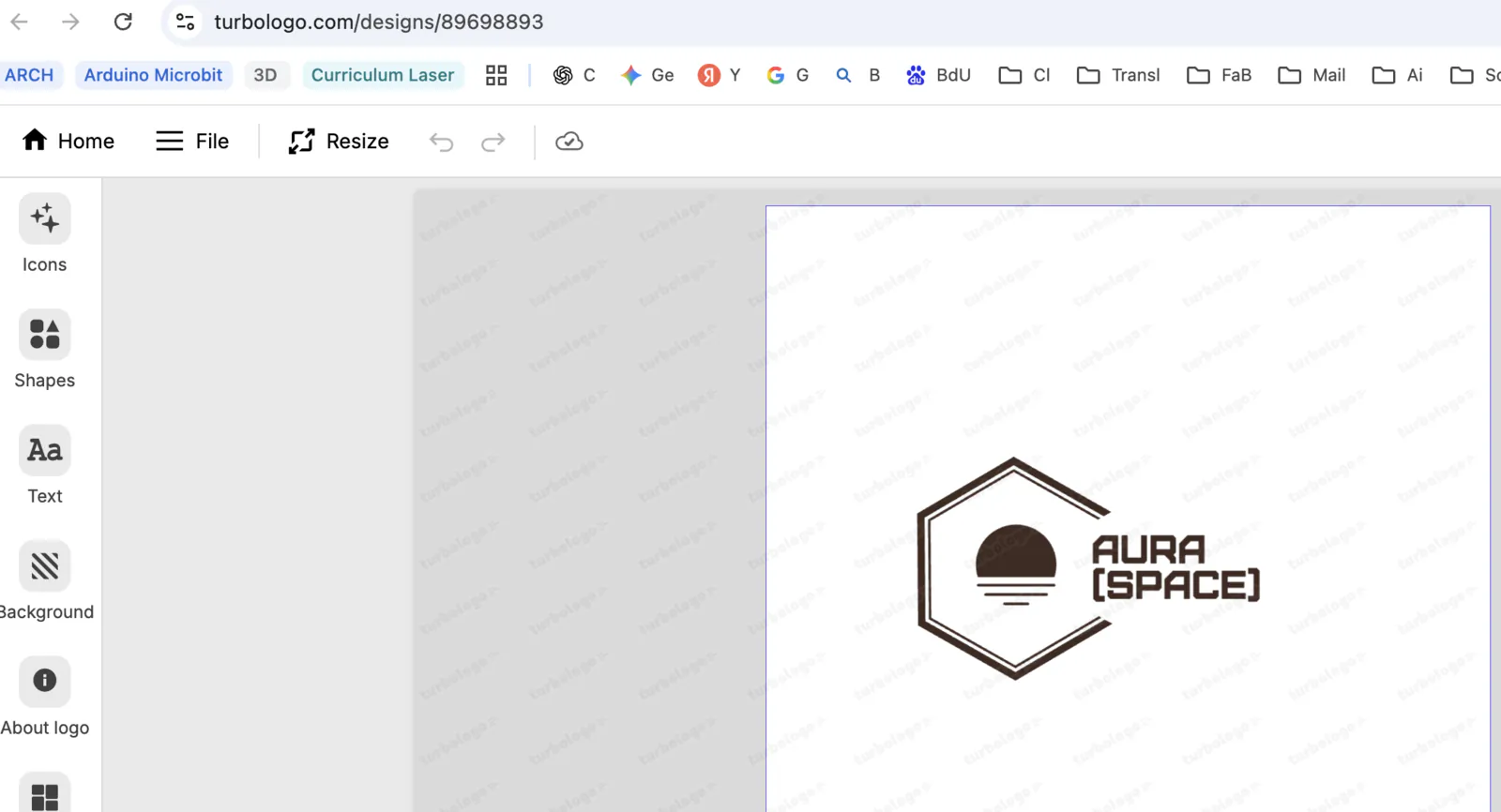
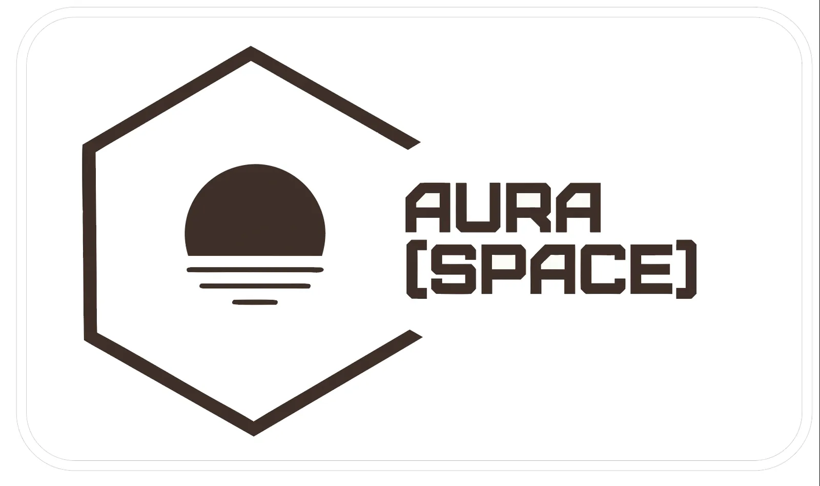
I decided to use logo generator services for inspiration, for example Turbologo.com. I added keywords, icons, and style options, then selected the one I liked most.
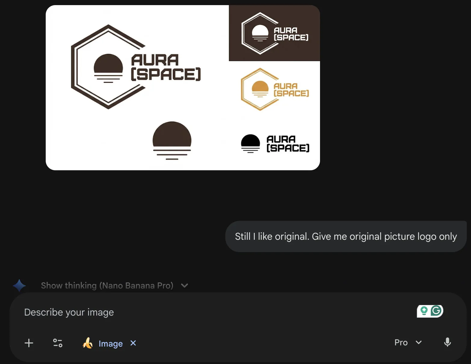
I copied the chosen logo into Gemini (Nano Banana) and asked for cleaned or similar versions. The generated outcomes were not good, and I still preferred the original one.
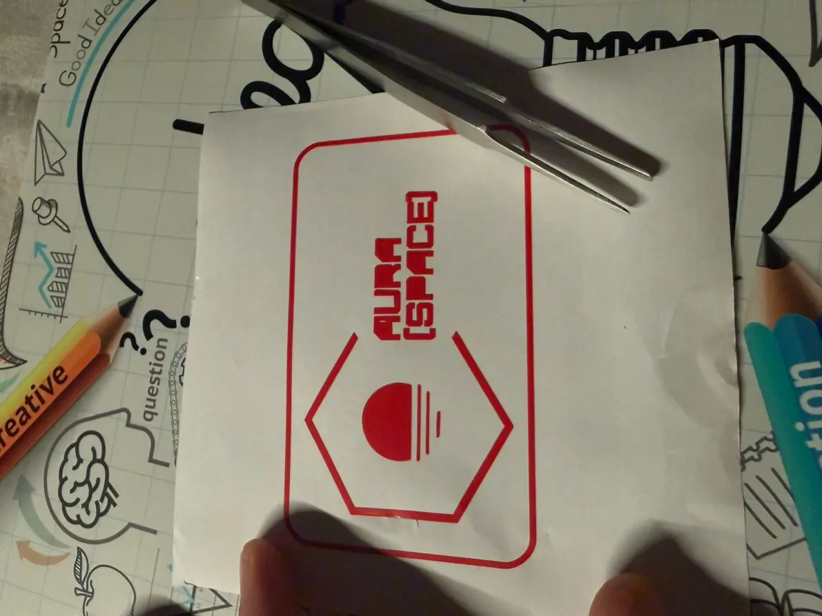
Then I searched how to vectorize an image and found Recraft.ai.
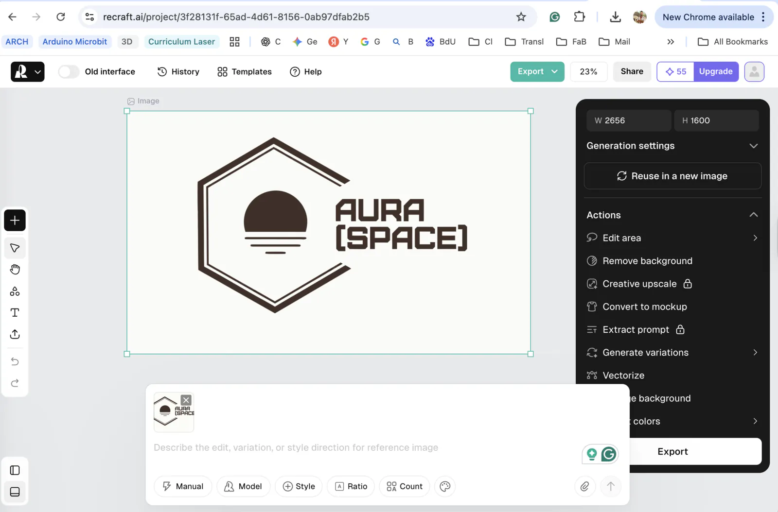
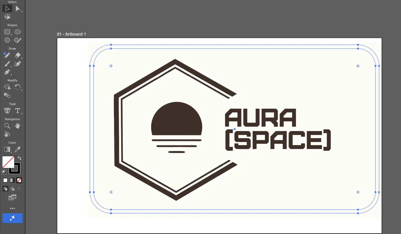
I saved and exported the SVG file into Adobe Illustrator for final adjustments. I added a frame and removed some minor lines.
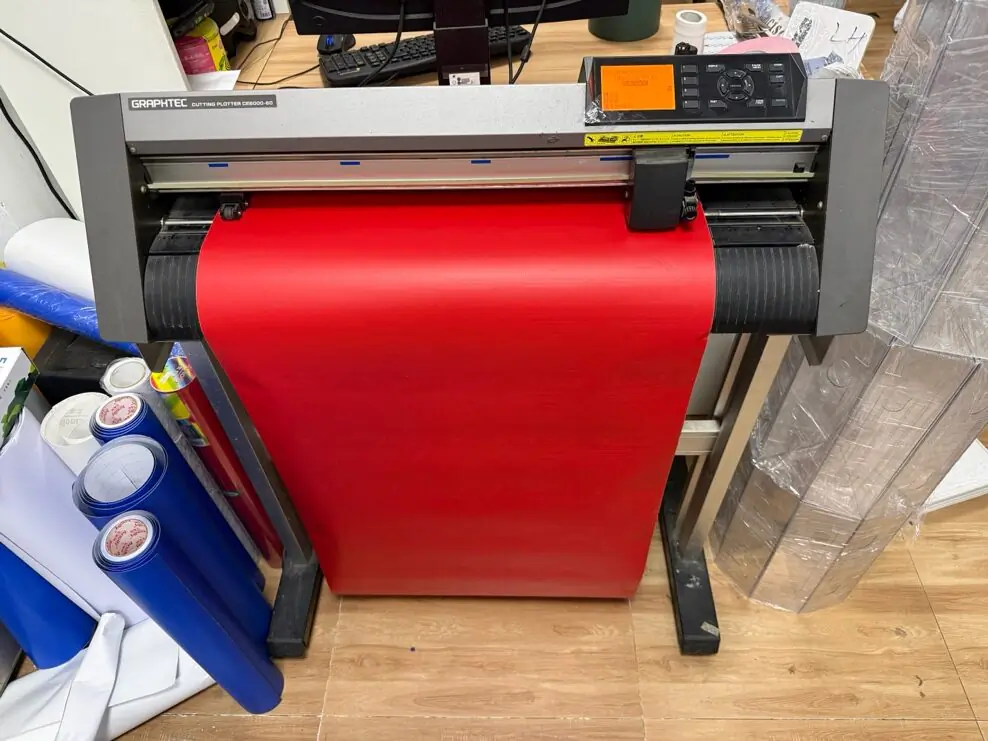
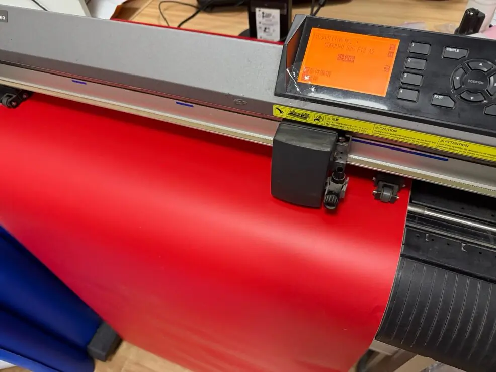
I found an advertising shop near my place with the right machine. Because the machine UI was in Chinese, I asked for help exporting it.
Some patches were cracked (around 3 out of 16). Next time the cutting speed should be slower, and the design should avoid very thin lines.
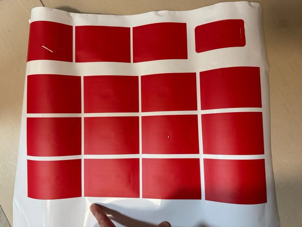
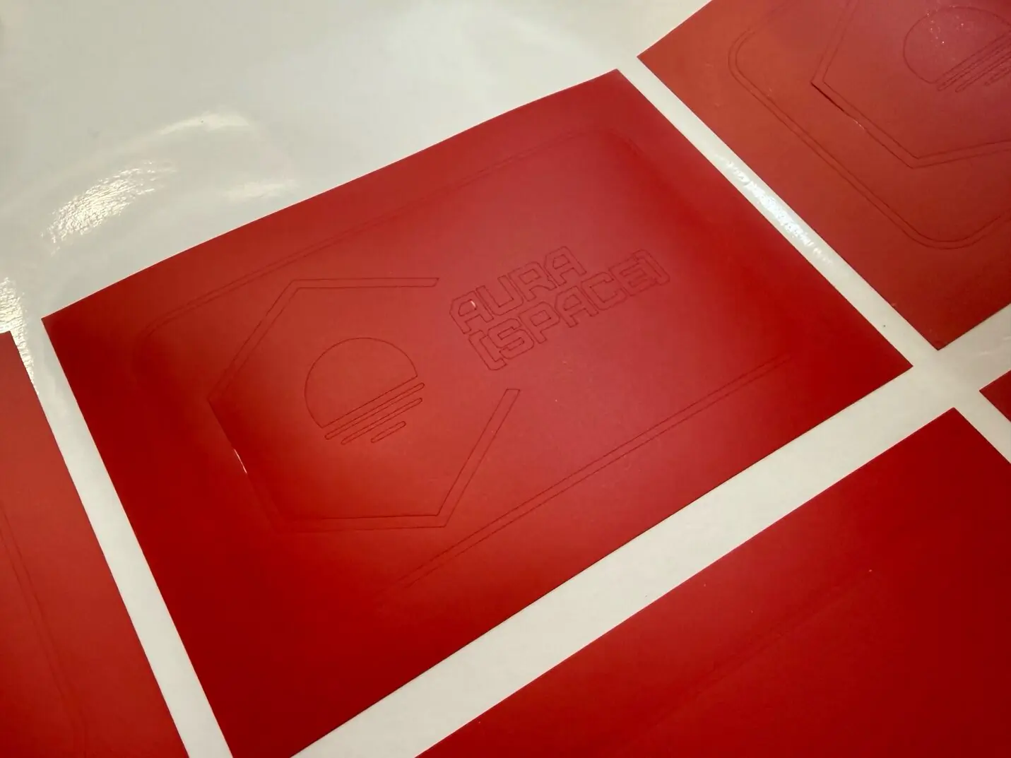
During placement, the small parts were not easy to position correctly. I got the idea that the initial design could be changed into one full patch with embossed letters and logo. The logo is okay, but letters need to be adjusted: bigger letters and letters with holes (like A and R) in stencil style.
Changing design with the same steps.

Design files
Design source files from this week are being organized and will be uploaded here in downloadable format.
- Download LaserCut sketch for 2.5 mm plywood (Triangle_2.39.lcpx)
- Download LaserCut sketch for 3.5 mm cardboard (Triangle_3.4.lcpx)
- Download logo vector (Logo 2 vector+frame.svg)
Week 3 reflection
This week helped me clearly understand what parametric design actually means in practice. Before Week 03, I had heard the term many times, but my understanding was still abstract - I knew it was "design with parameters," but I did not fully feel why it matters. After watching several tutorials and doing my own research, I finally connected the idea to a real workflow: in CAD, parametric design means creating named variables for key dimensions (thickness, slot width, spacing, etc.), almost like in programming. The design becomes based on these variables, so instead of rebuilding everything from scratch, I can update a few values and the geometry changes automatically in a controlled and predictable way.
Once I set up my first parametric sketch correctly (constraints, dimensions, and logical relationships), the process became surprisingly fast. The biggest "aha moment" was seeing how easy it is to modify shapes: instead of redrawing geometry, I only needed to adjust a few key values and the entire structure updated automatically. It felt like switching from drawing to building a system. That changed my attitude to design - now I want to invest time early to build a clean parametric structure, because it saves a lot of time later.
I also got inspiration from online examples of parametric construction kits, and it pushed me to explore Fusion 360 deeper. It was not only about making one object - it was about understanding how to design a kit that can adapt to different materials and tolerances. That idea connected well with digital fabrication: real-world materials often do not match their labeled thickness, so being able to quickly update parameters is a practical advantage, not just a nice feature.
For the vinyl cutter part, I enjoyed working on a design that is more graphic and clean. It made me think differently about vectors: simplifying shapes, considering negative space, and preparing files in a way that will cut reliably. It also reminded me that fabrication is not only about making things - it is about designing for a process and respecting the limitations of the machine.
This week I also experimented with AI tools (Google Gemini) to help with visual references and quick representations. It was useful for generating ideas and helping me see a concept faster, but it was not precise enough to trust directly for technical work. This was another important lesson: AI is helpful for inspiration and speed, but it can confidently produce mistakes, so I must always verify dimensions, geometry, and final outputs myself. For my workflow, AI is more like a creative assistant, not an engineering authority.
Finally, I spent time improving my documentation website. I adjusted layout and formatting, and the page now looks cleaner and more structured. I am happy that I am slowly building a stronger documentation habit, because in Fab Academy, documentation is not extra work - it becomes part of the learning process. Each week, my goal is to make the page clearer, more visual, and easier to follow, both for myself and for anyone who reads it later.