Week 04 — Embedded Programming
Group assignment
- Demonstrate and compare the toolchains and development workflows for available embedded architectures.
The group assignment for this week was completed by Lin and Winnie. Their documentation is available on Lin's Week 4 page and Winnie's Week 4 page.
Individual assignment
- Browse through the data sheet for a microcontroller.
- Write and test a program for an embedded system using a microcontroller to interact (with input and/or output devices) and communicate (with wired or wireless connections).
- Extra credit: assemble the system.
- Extra credit: try different languages and/or development environments.
Learning outcomes
Checklist
- Linked to the group assignment page
- Documented what you learned from reading a microcontroller datasheet
- What questions have been answered
- Explained how you programmed the board
- Included your code
- Included a ‘hero shot’ of your board
W4 Documentation
Some general knowledge interpretation
I linked the lecture page and my notes to ChatGPT and had a conversation to clarify the fundamentals. Below are the highlights I used to build my Week 4 understanding.
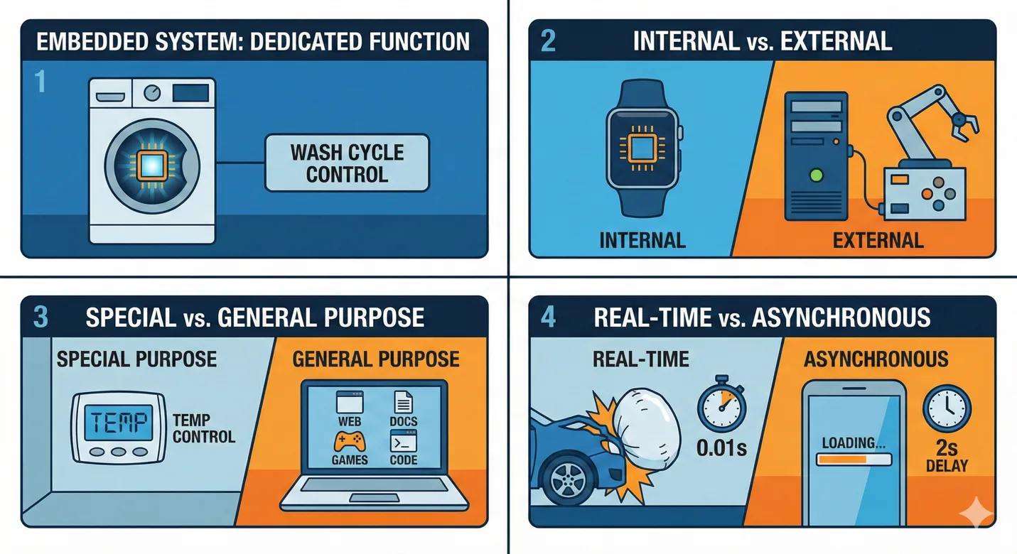
- Embedded system: a specialized computer integrated into a device for a dedicated function.
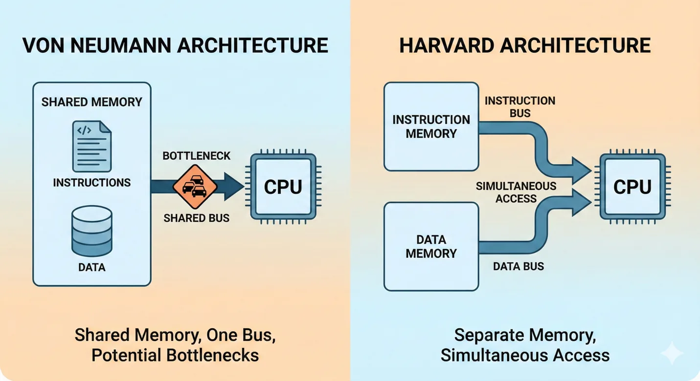
- Architecture: Von Neumann vs Harvard memory models and their tradeoffs.
- RISC vs CISC: instruction-set style and execution behavior.
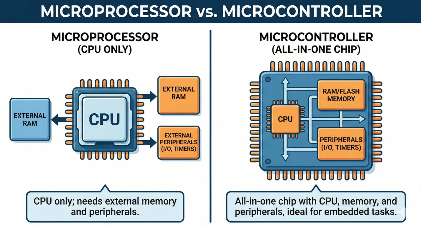
- Microprocessor vs microcontroller: external components vs all-in-one integration.

Research focus
First, I need to determine the area of research. I uploaded the whole lecture transcripts to ChatGPT and asked this question:
So in Neil’s class, he presented a lot of microcontrollers, and which of the top four is better to deep dive,
deep research, so for my project, because I need to control lights, which does not need too much frequency,
just needs to be easier to program, so probably it's ATTiny412. Then in the future, I will need Wi-Fi and Bluetooth
to connect with other devices, so which is probably use ESP32. And another one, which is also famous and easy to start,
so give me suggestions.
ChatGPT reply about the four microcontrollers:
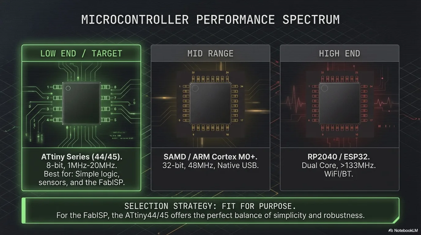
- ATtiny412: simple and low-cost for basic light control.
- ESP32: Wi-Fi + Bluetooth for connected IoT use.
- RP2040: easy prototyping, strong middle step.
- SAMD21: clean ARM Cortex-M0+ platform used in many boards.
I created 5 NotebookLM pages: one for lecture materials and one for each microcontroller datasheet.

Datasheet links used for the analysis:
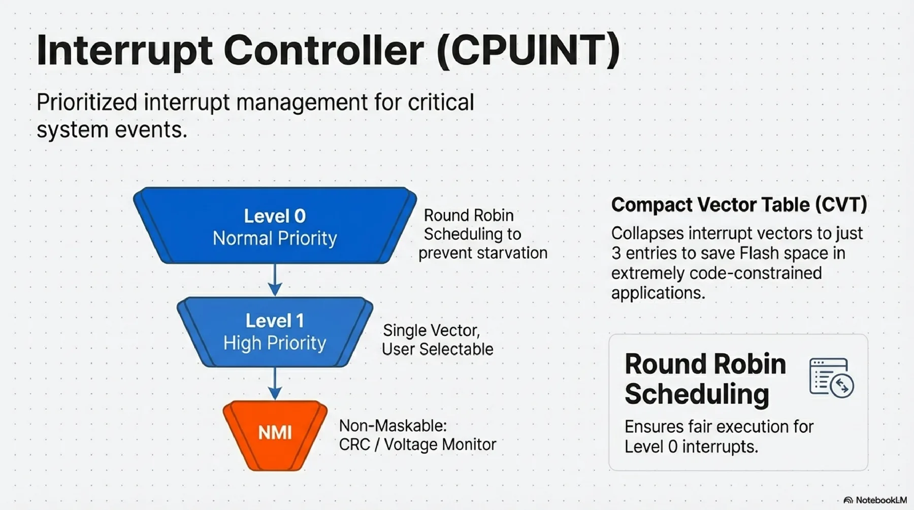
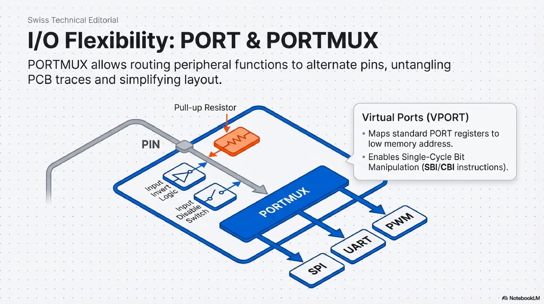
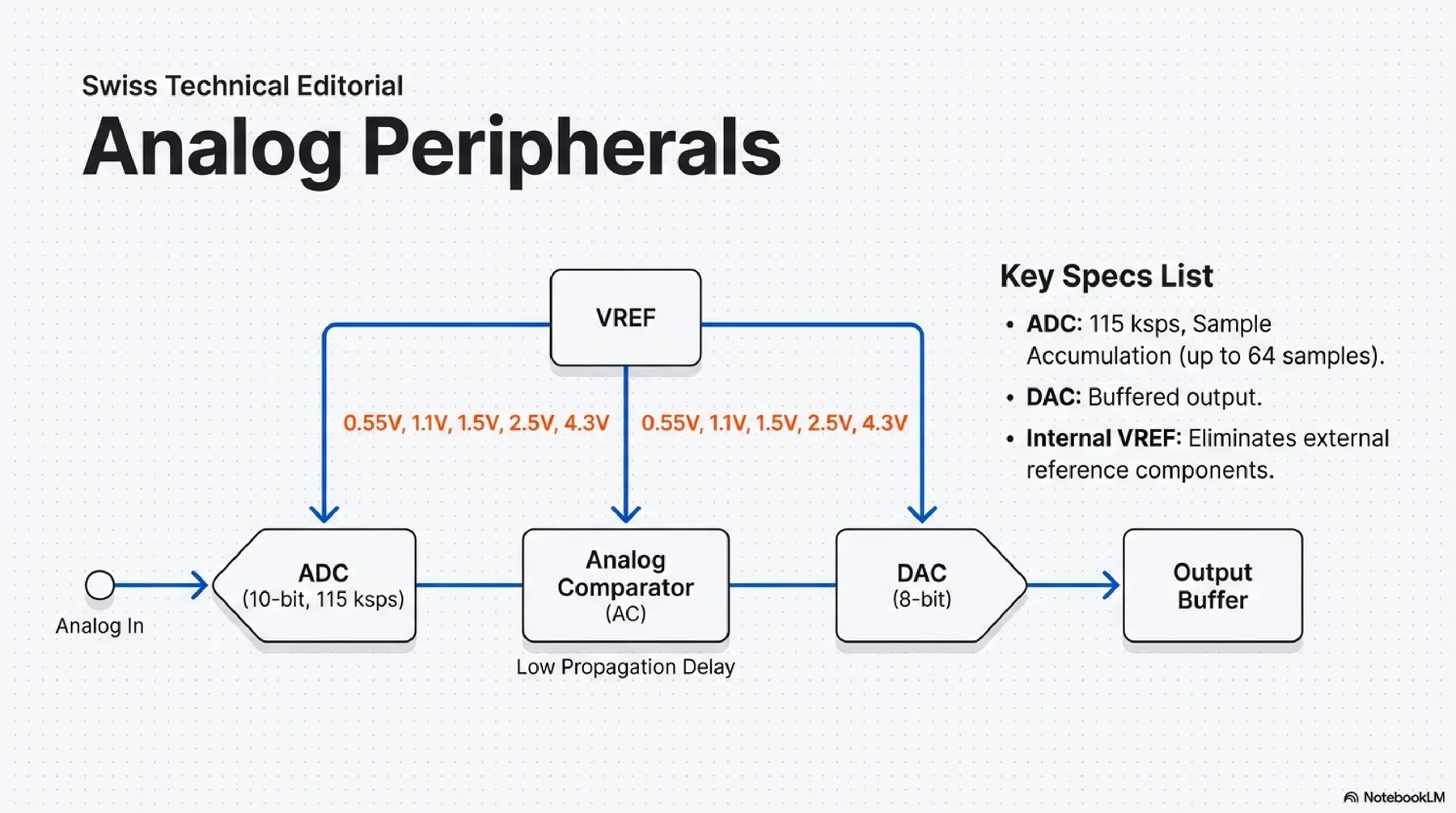
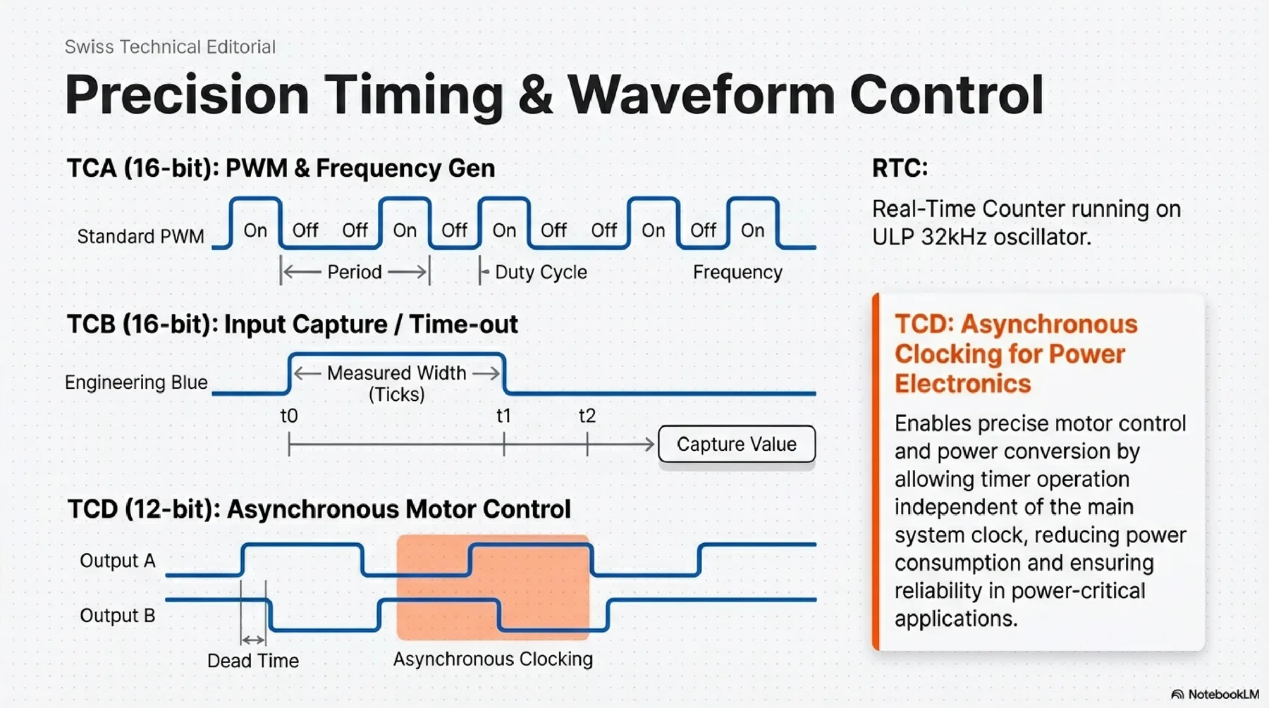
ATtiny412
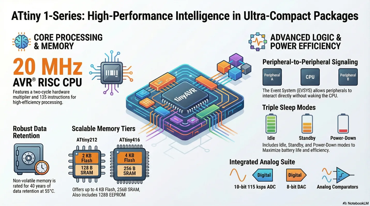
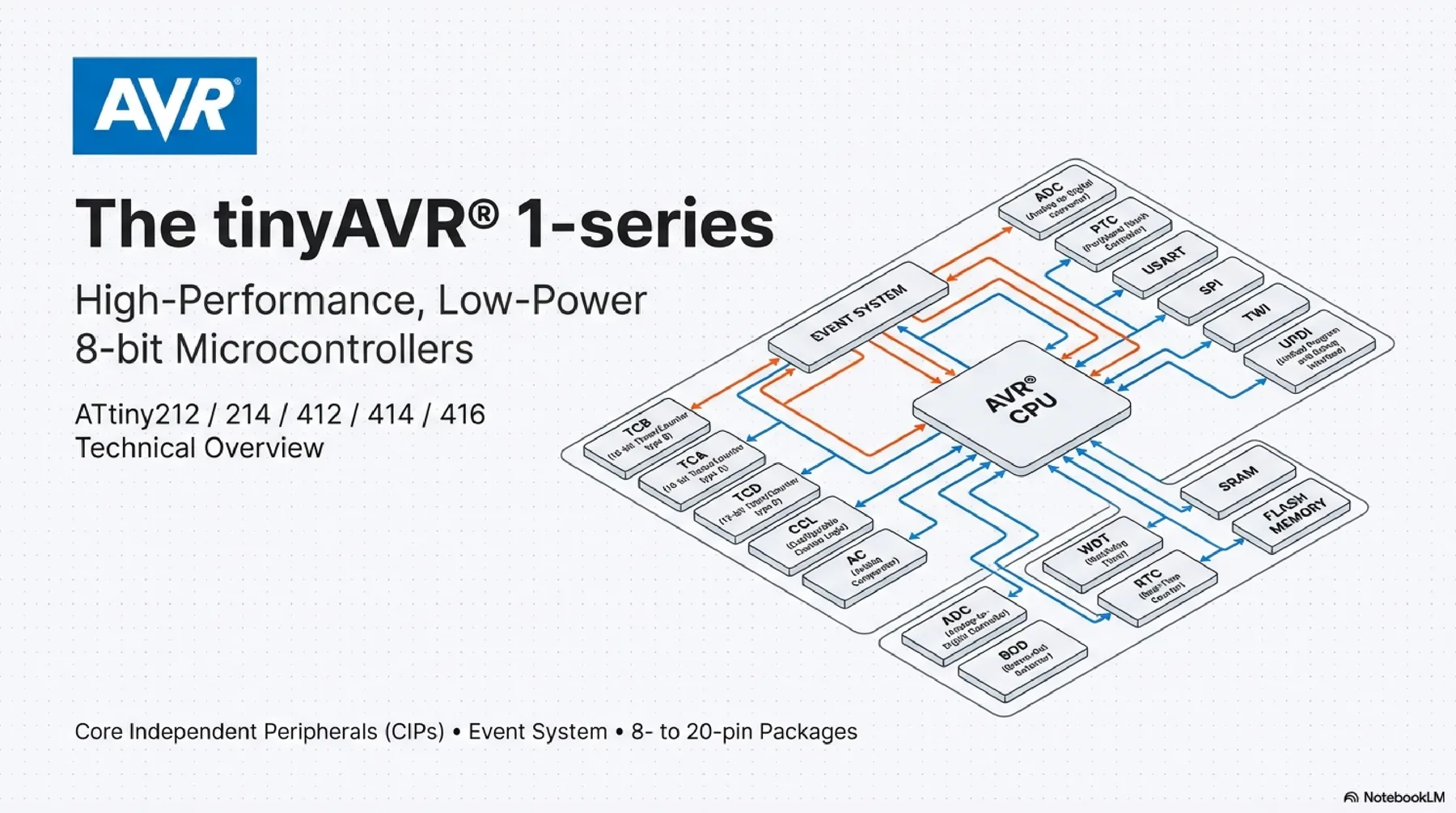
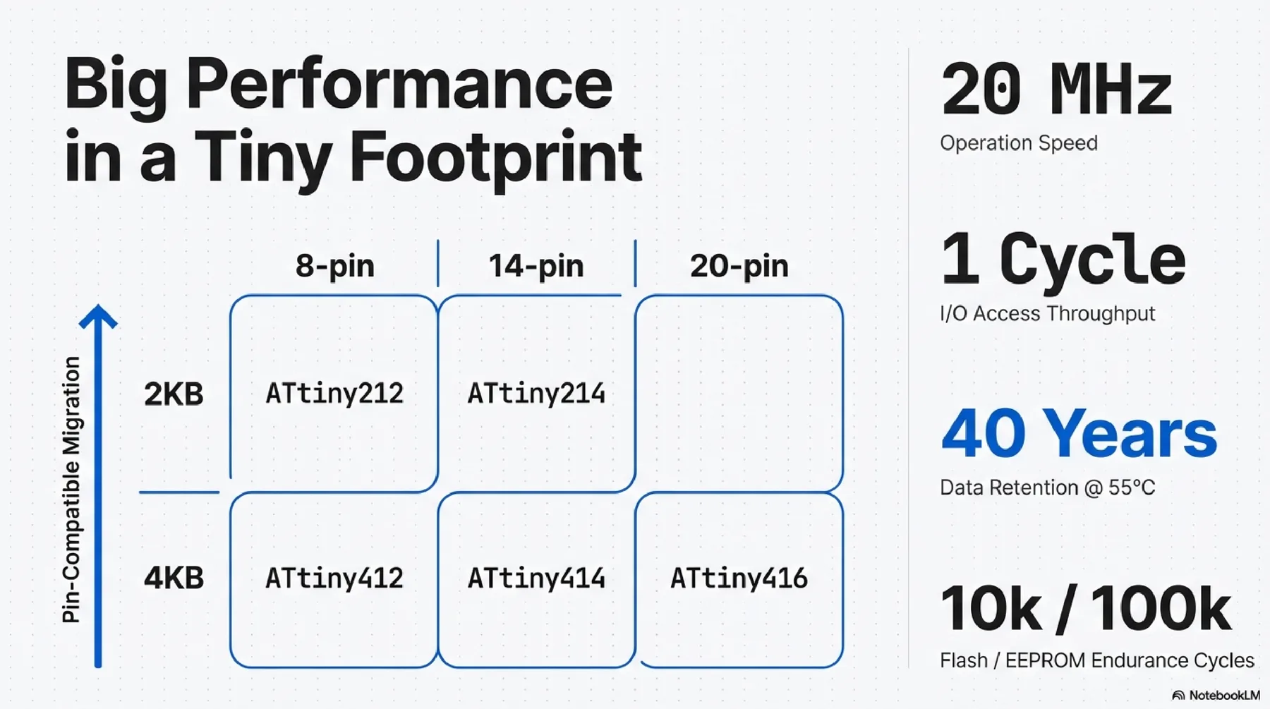
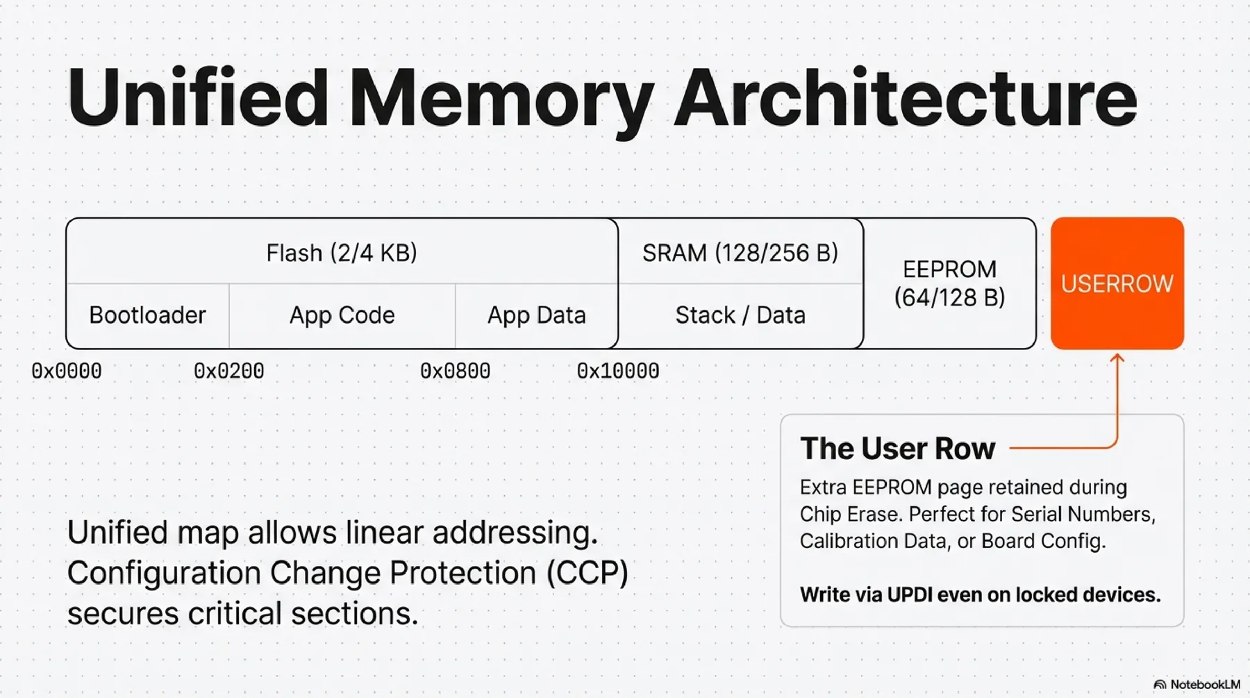
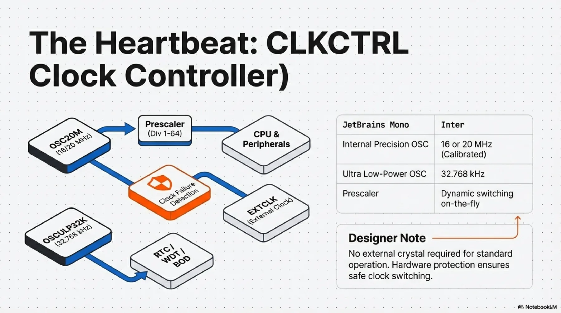
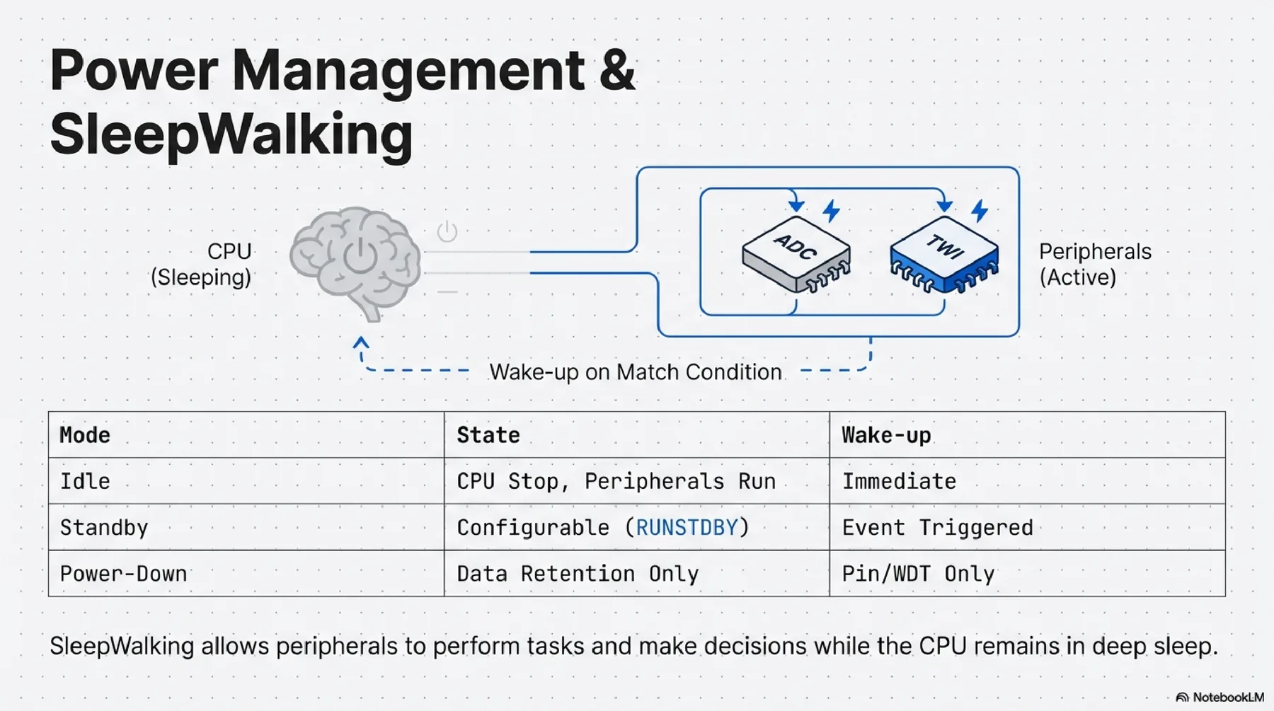
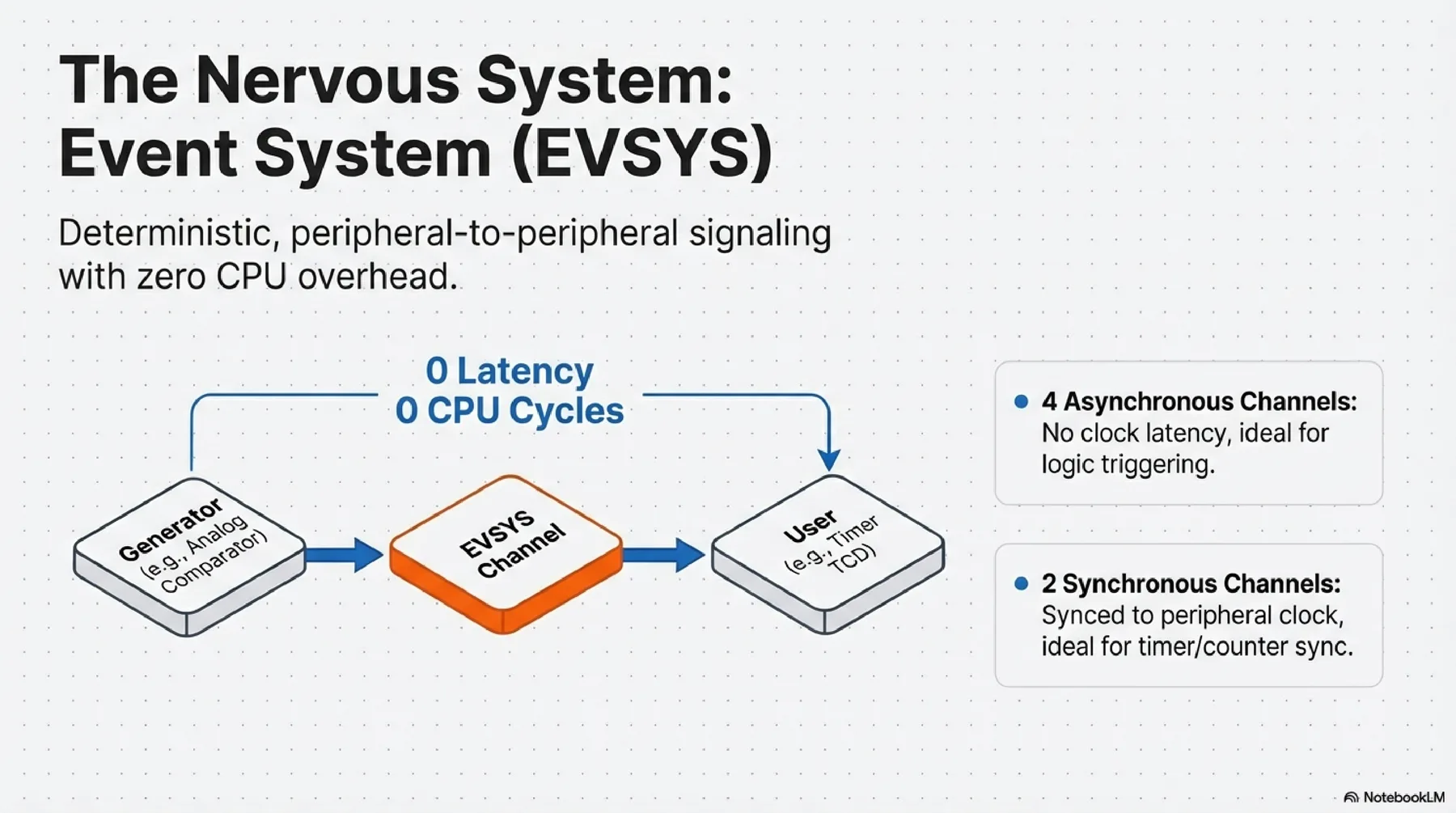
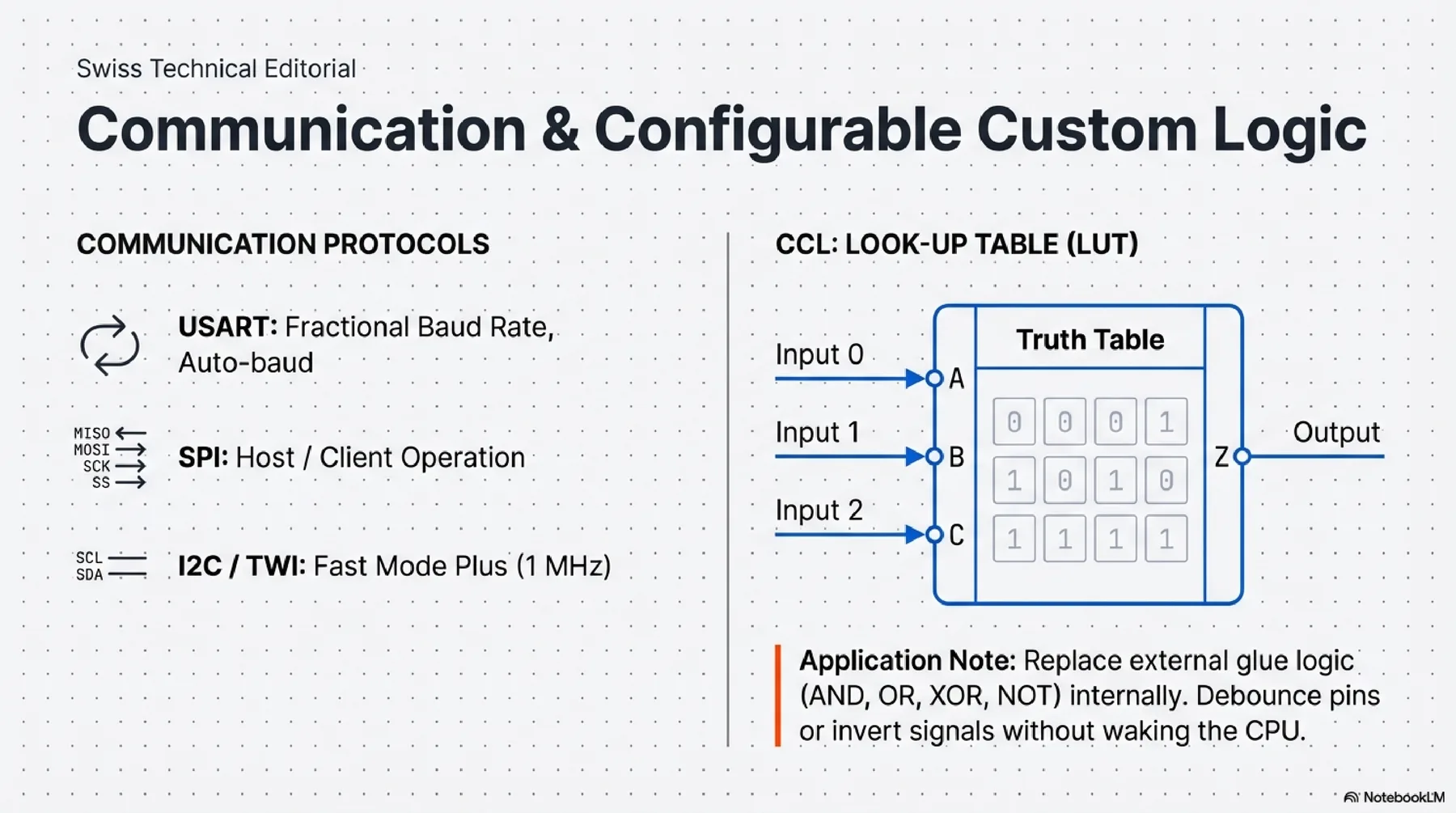
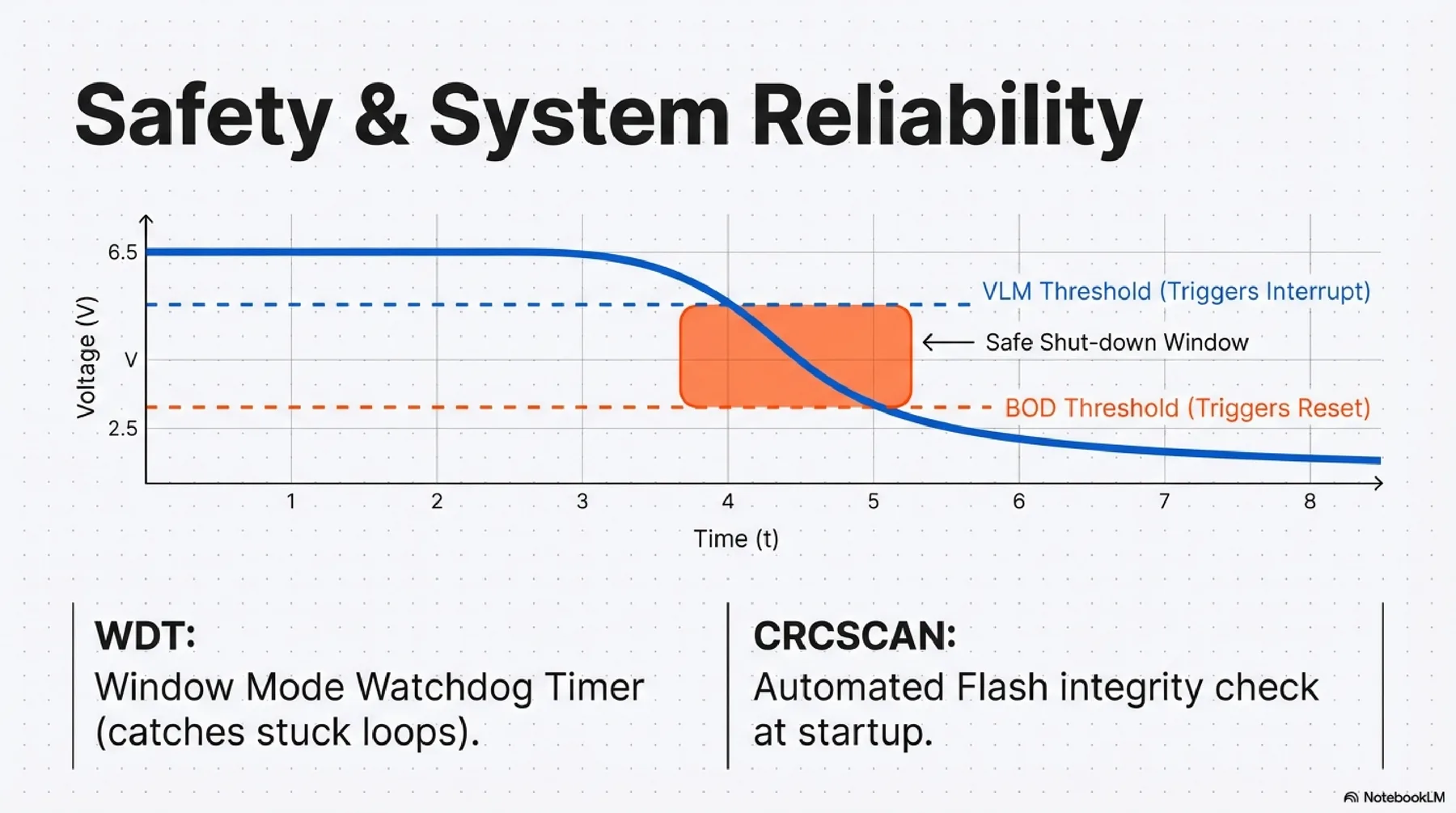
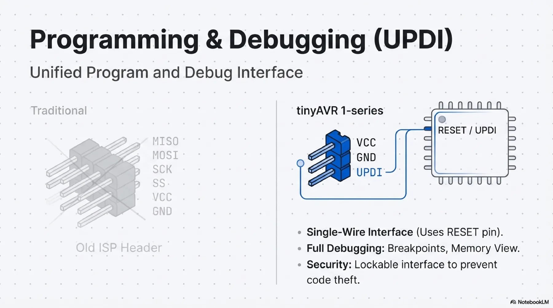
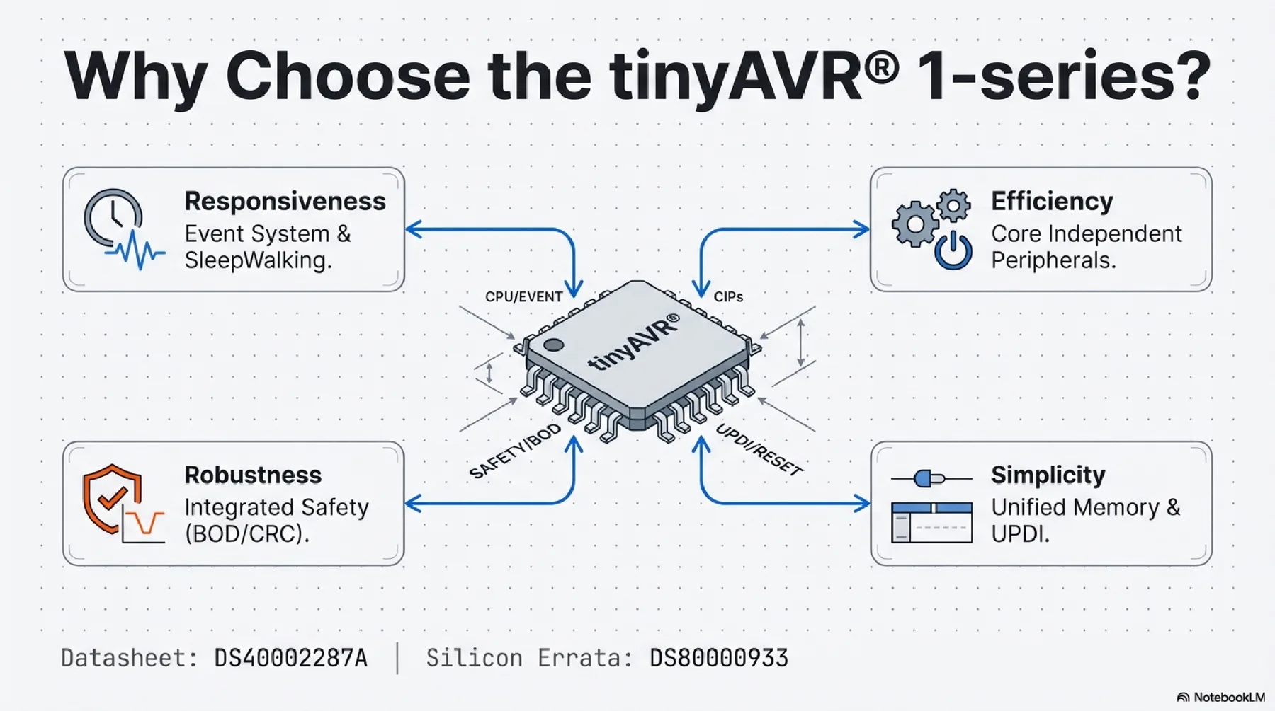
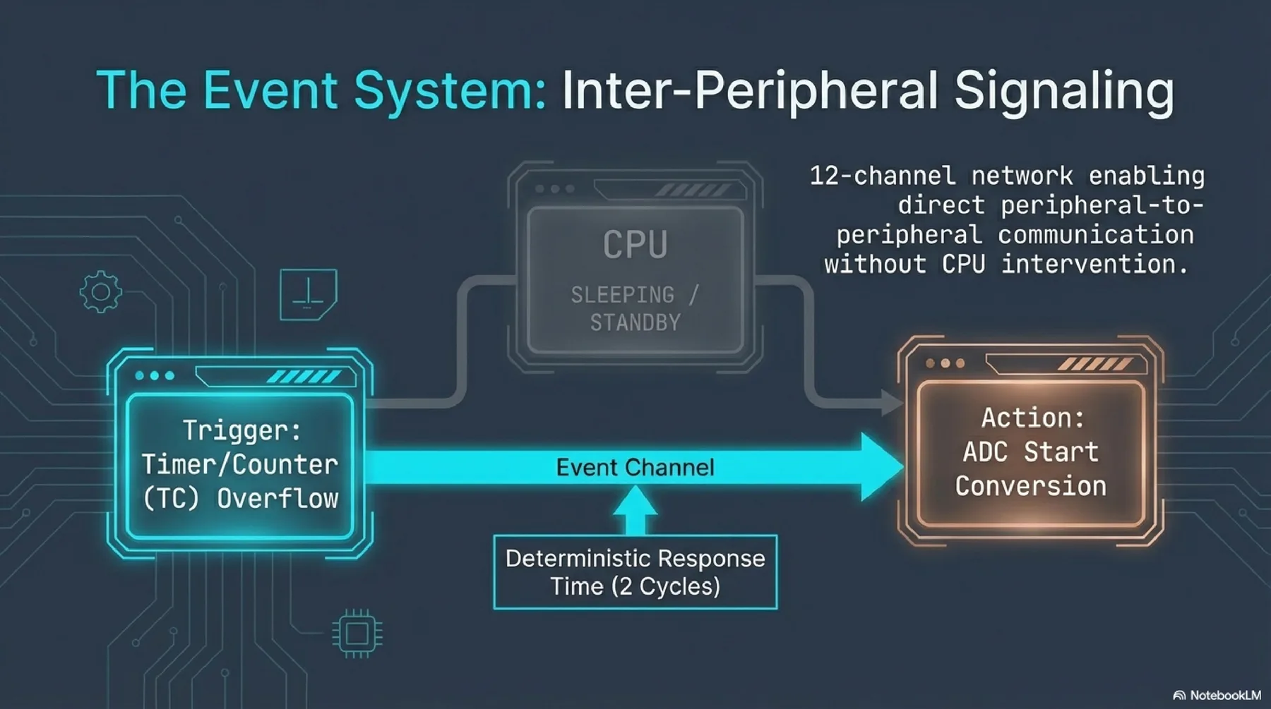
ATtiny412 (tinyAVR 1-series) is a compact 8-bit RISC microcontroller up to 20 MHz with integrated Flash/SRAM/EEPROM, event system support, timers, ADC, and serial interfaces (USART/SPI/TWI). It is a good fit for minimal embedded control.
Helpful reference video: Programming ATtiny with Arduino Nano
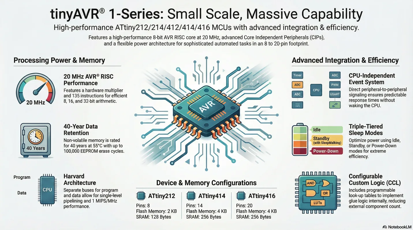
More detailed presentation about selected microcontroller (ATtiny412)

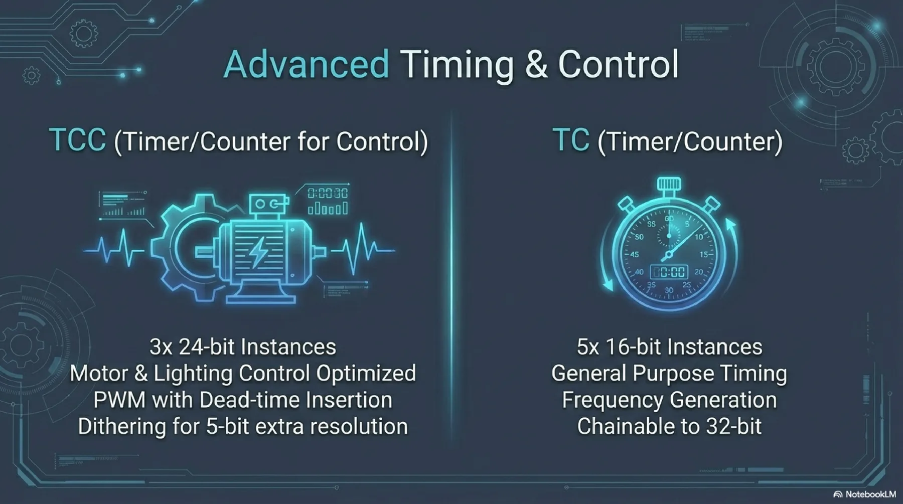
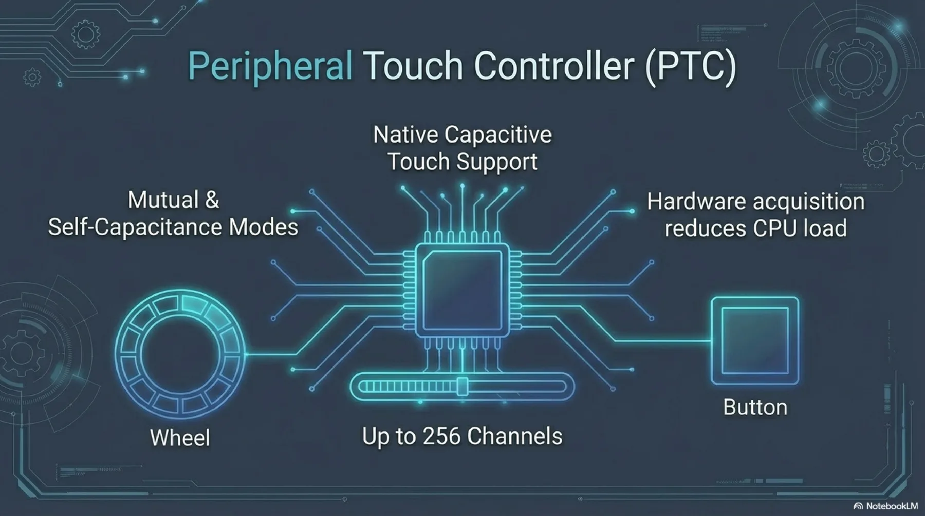
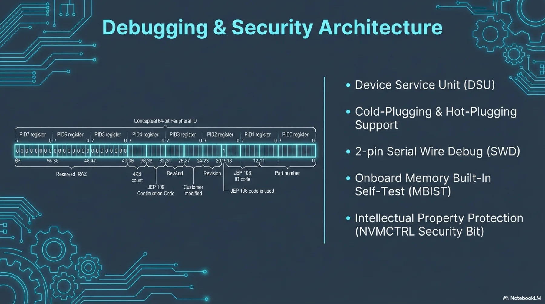
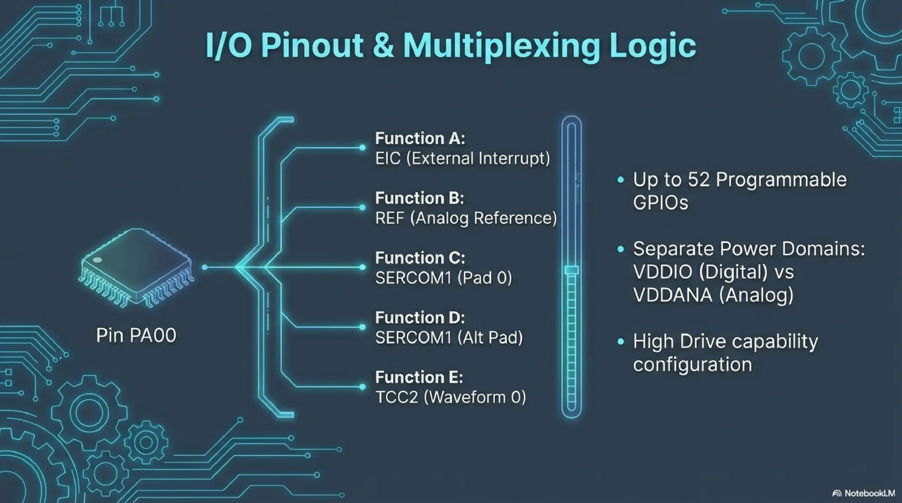
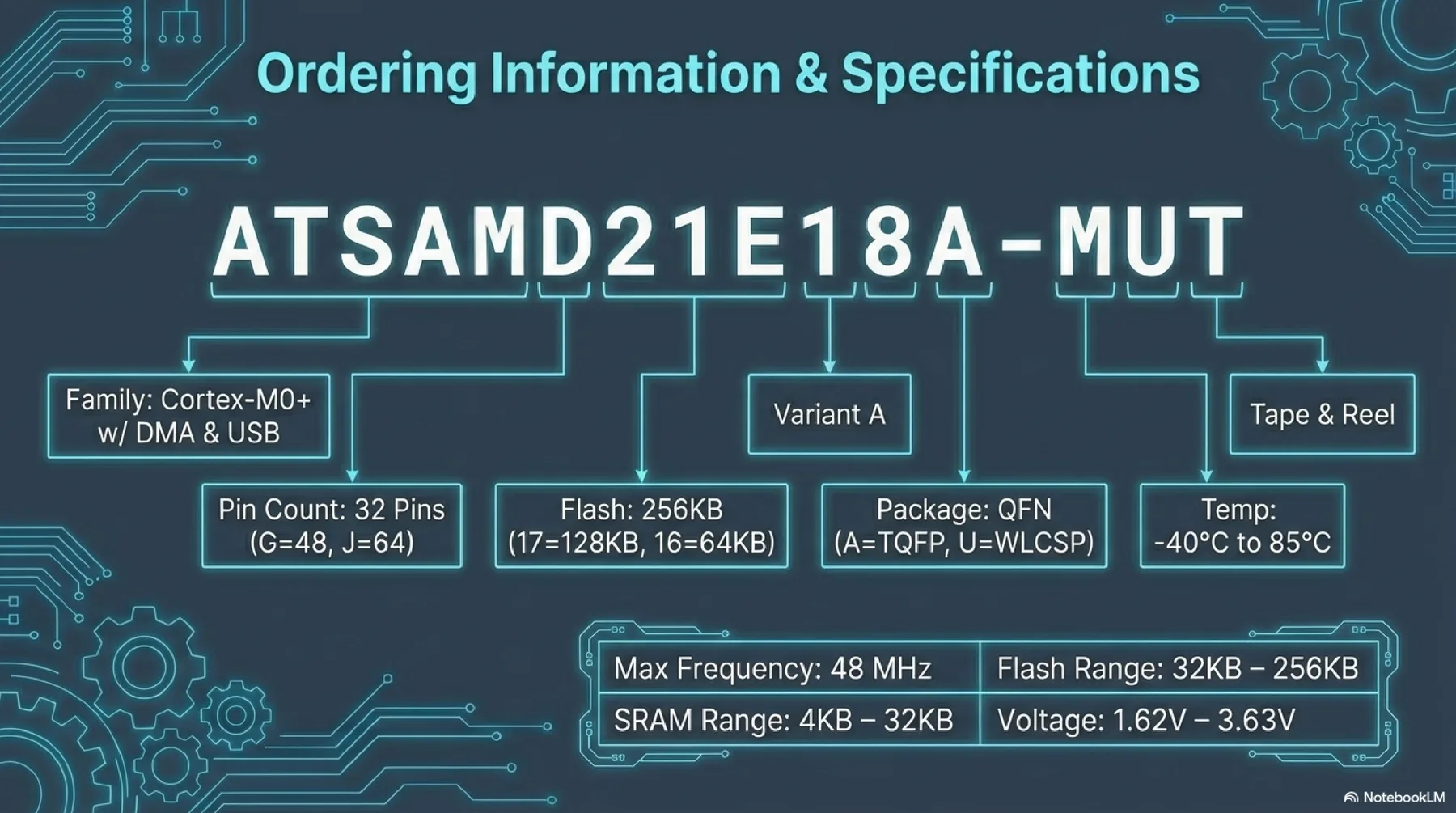
SAMD21
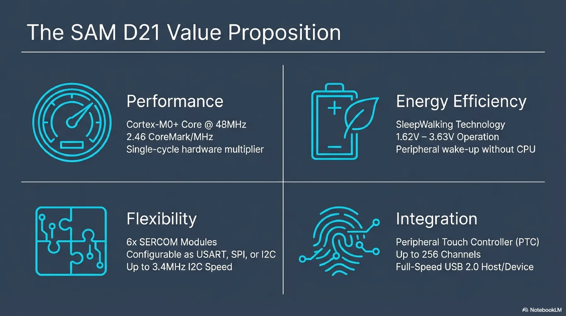
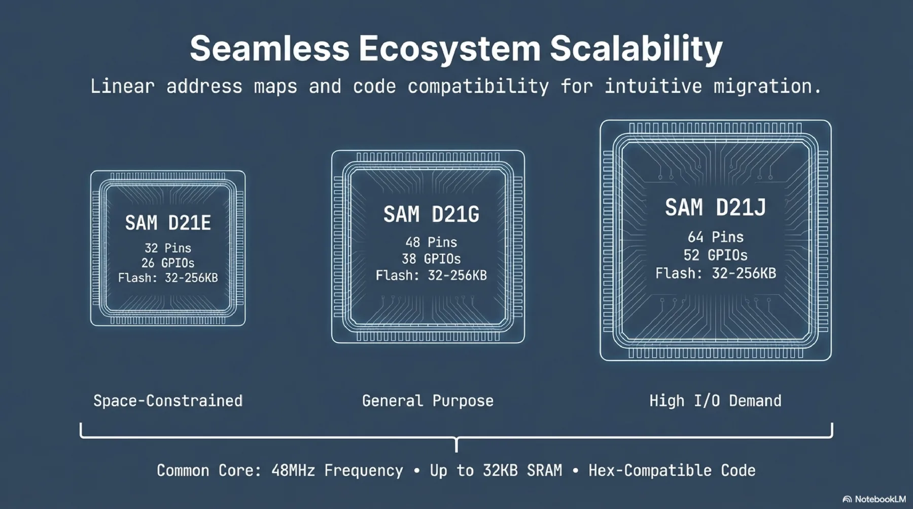
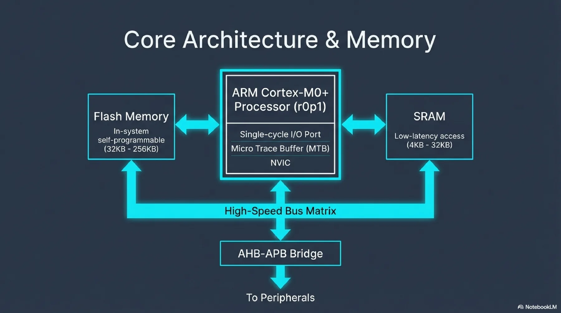
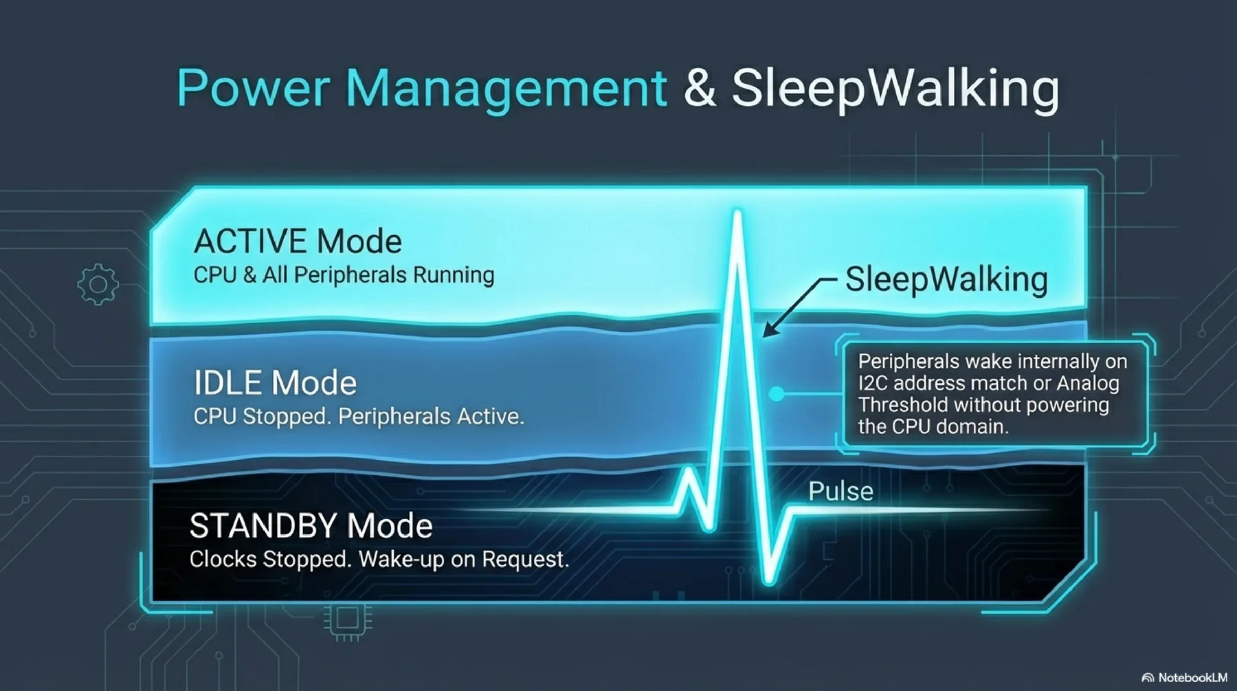
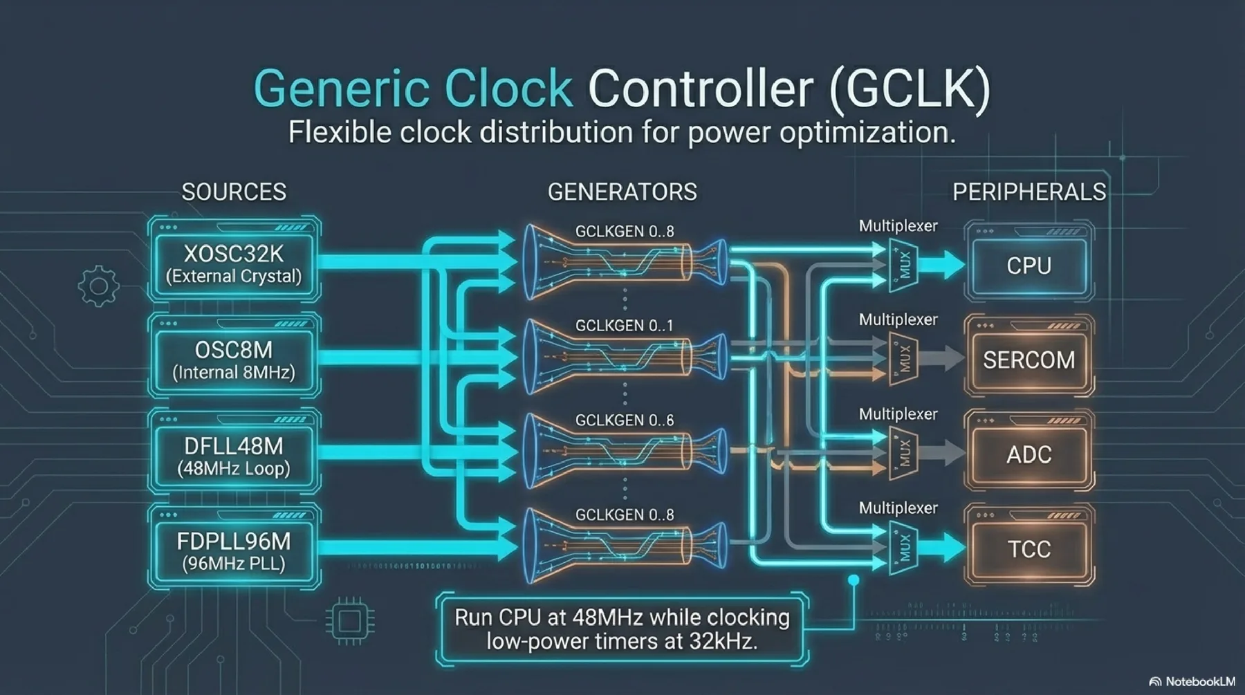
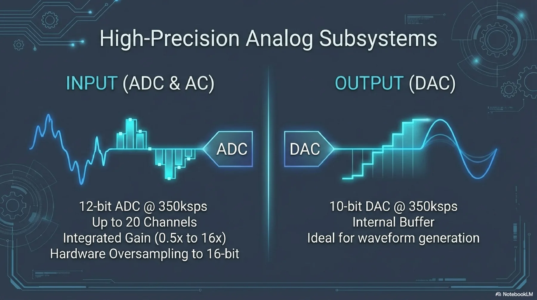
SAMD21 is a 32-bit ARM Cortex-M0+ platform with a broad set of peripherals, low-power operation modes, and strong Arduino ecosystem support. It is a practical bridge from AVR to more advanced ARM workflows.
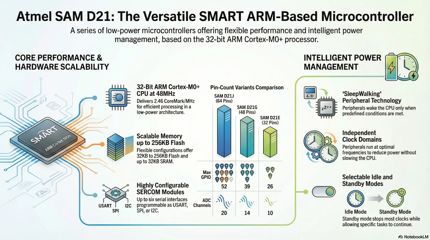
More detailed presentation about selected microcontroller (SAMD21)


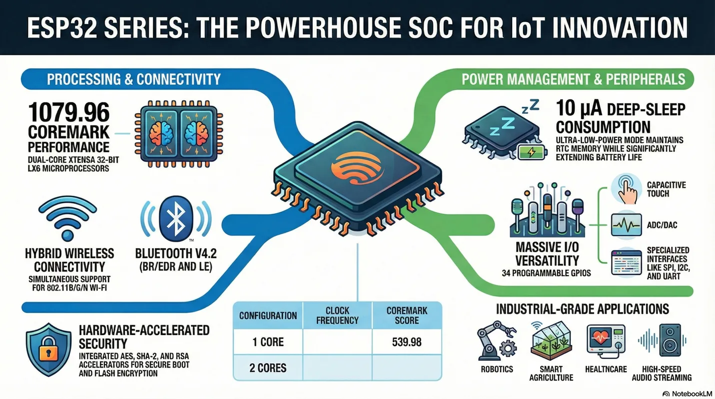
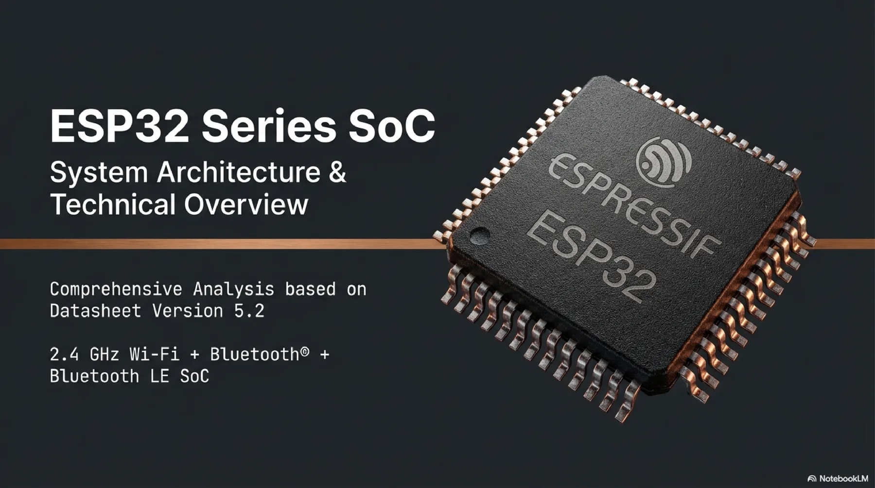
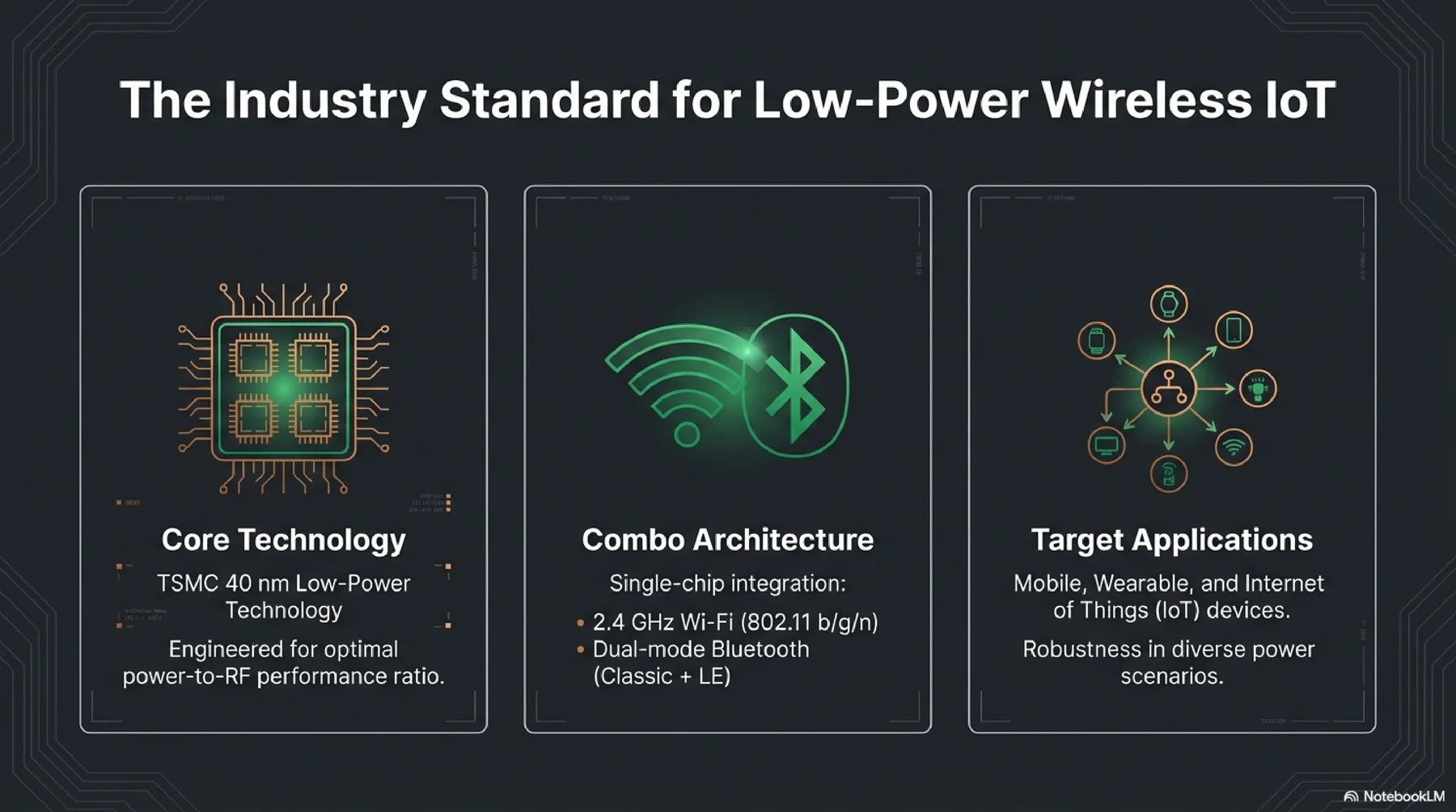
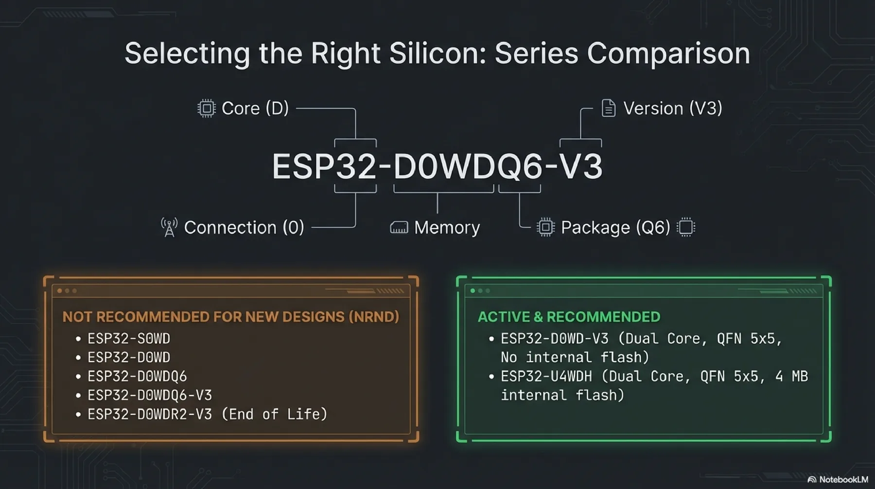
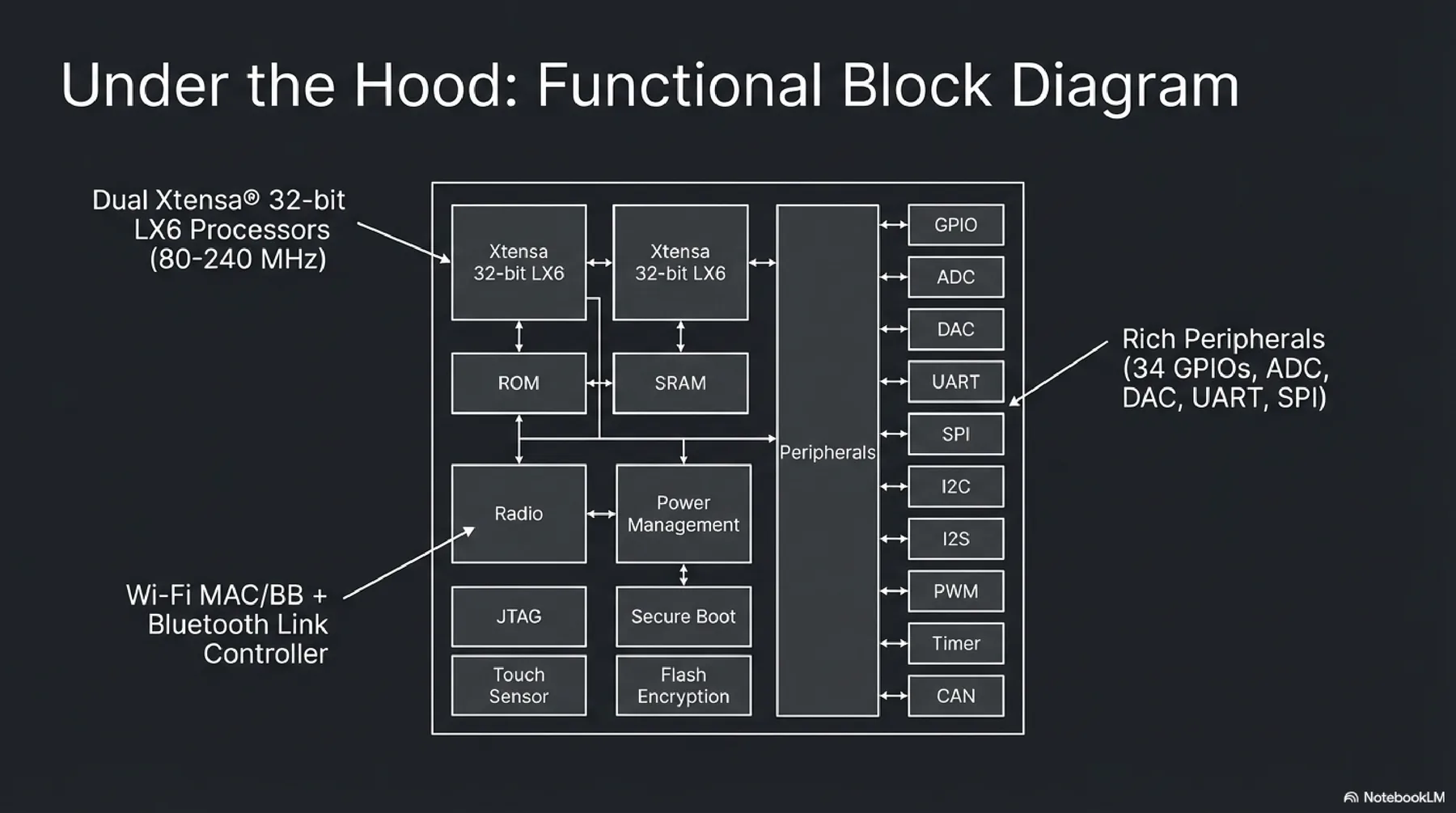
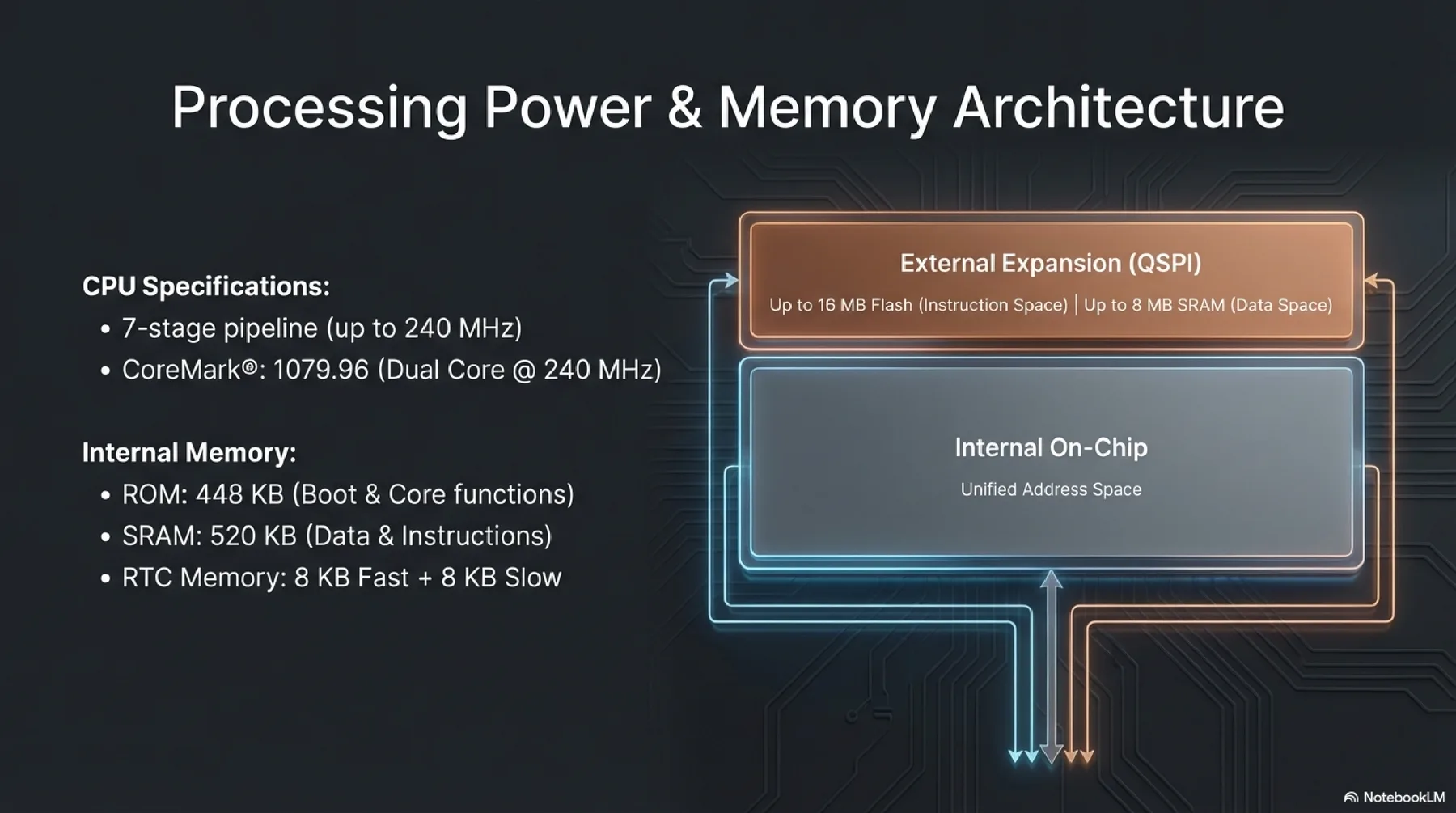
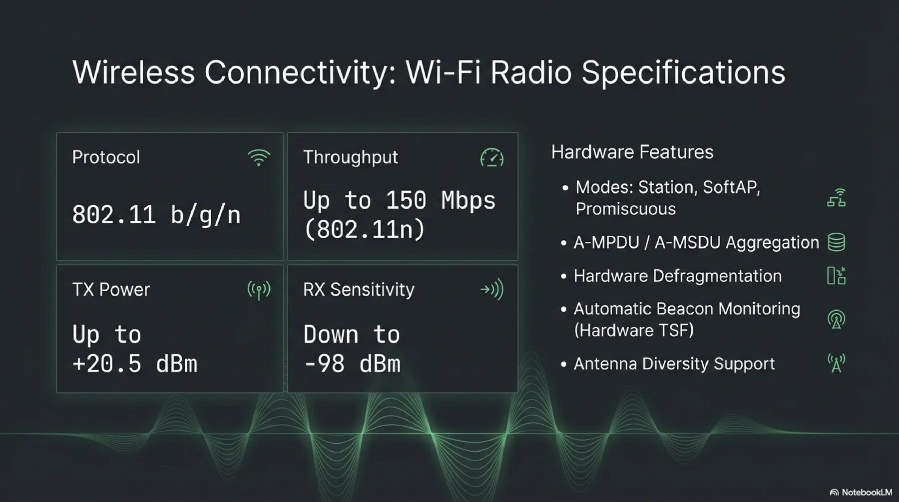
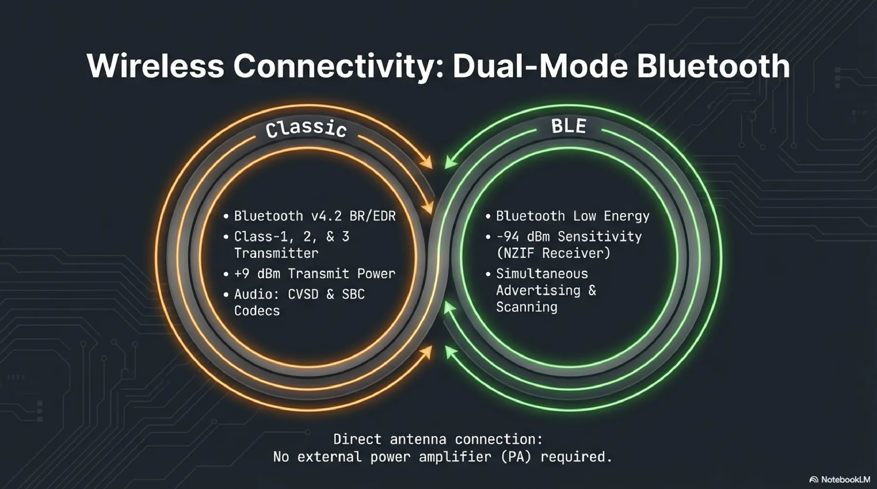
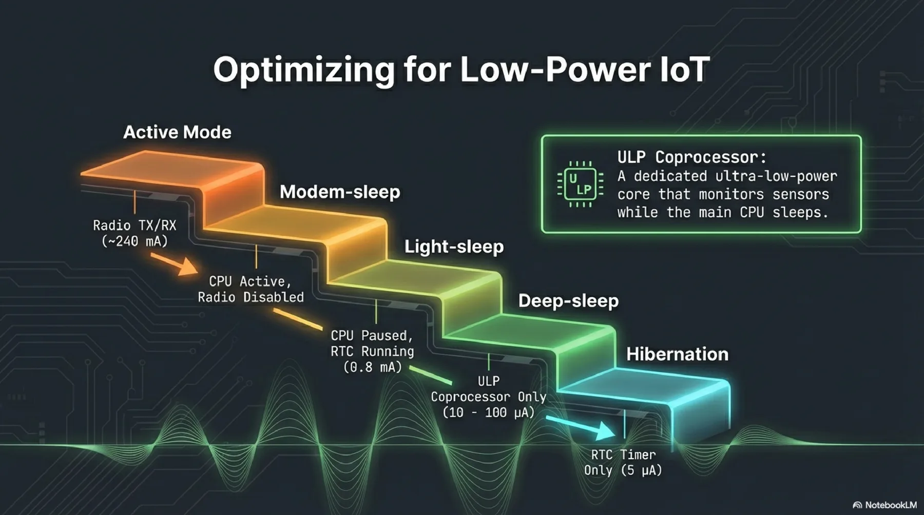
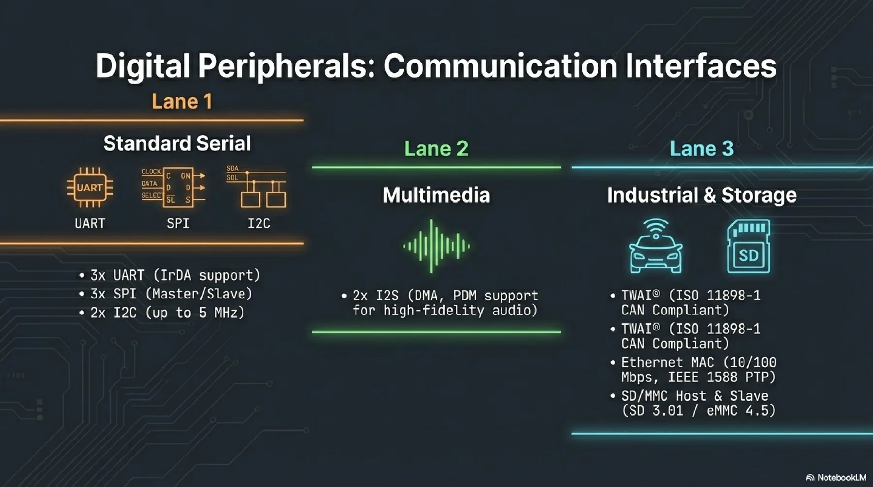
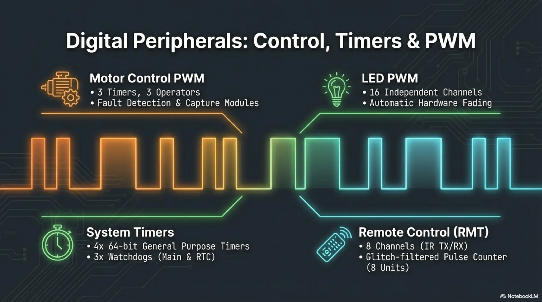
ESP32
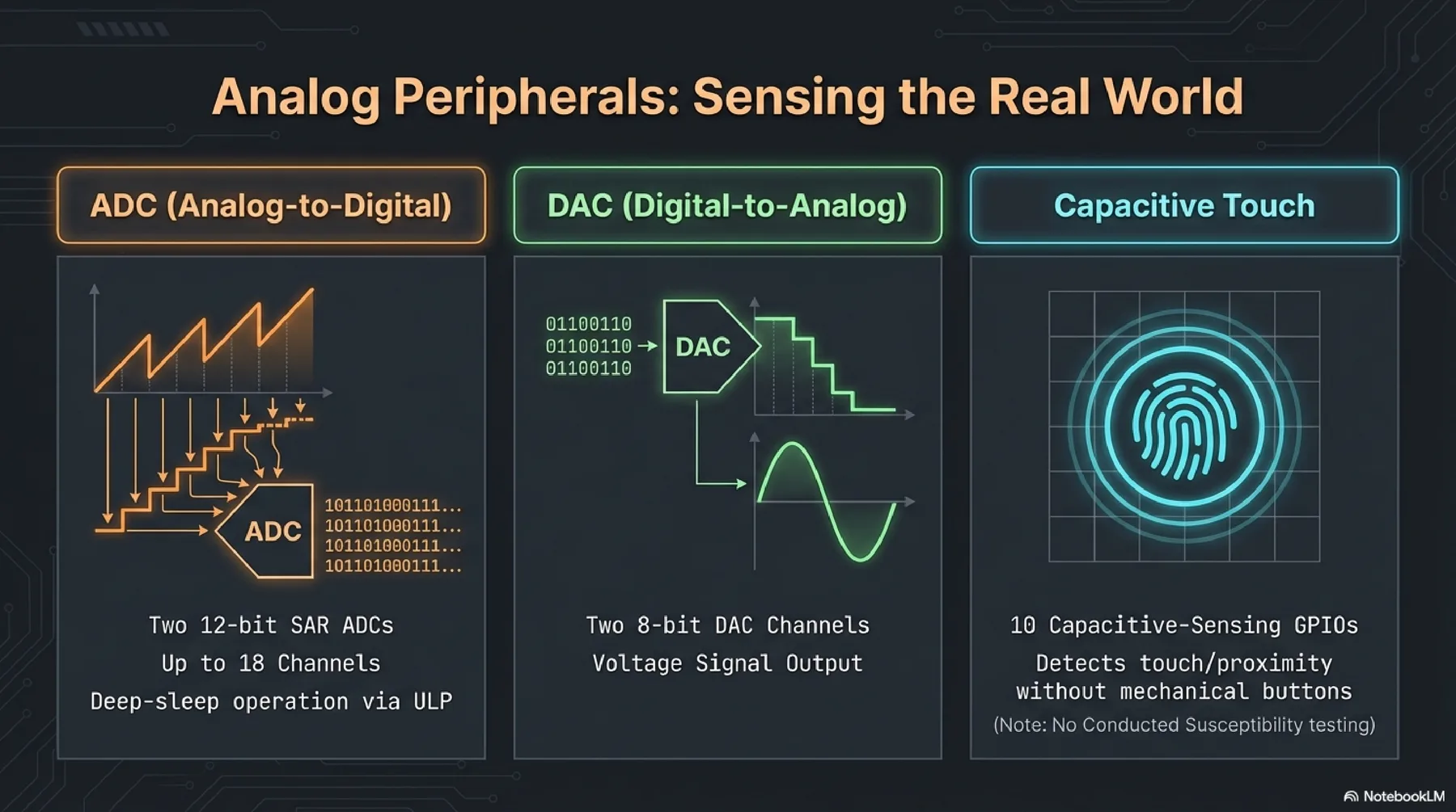
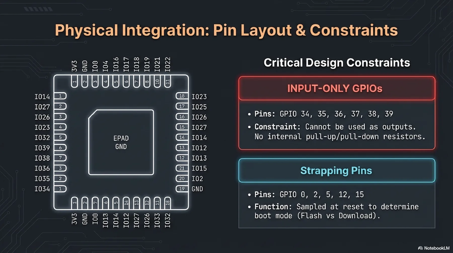
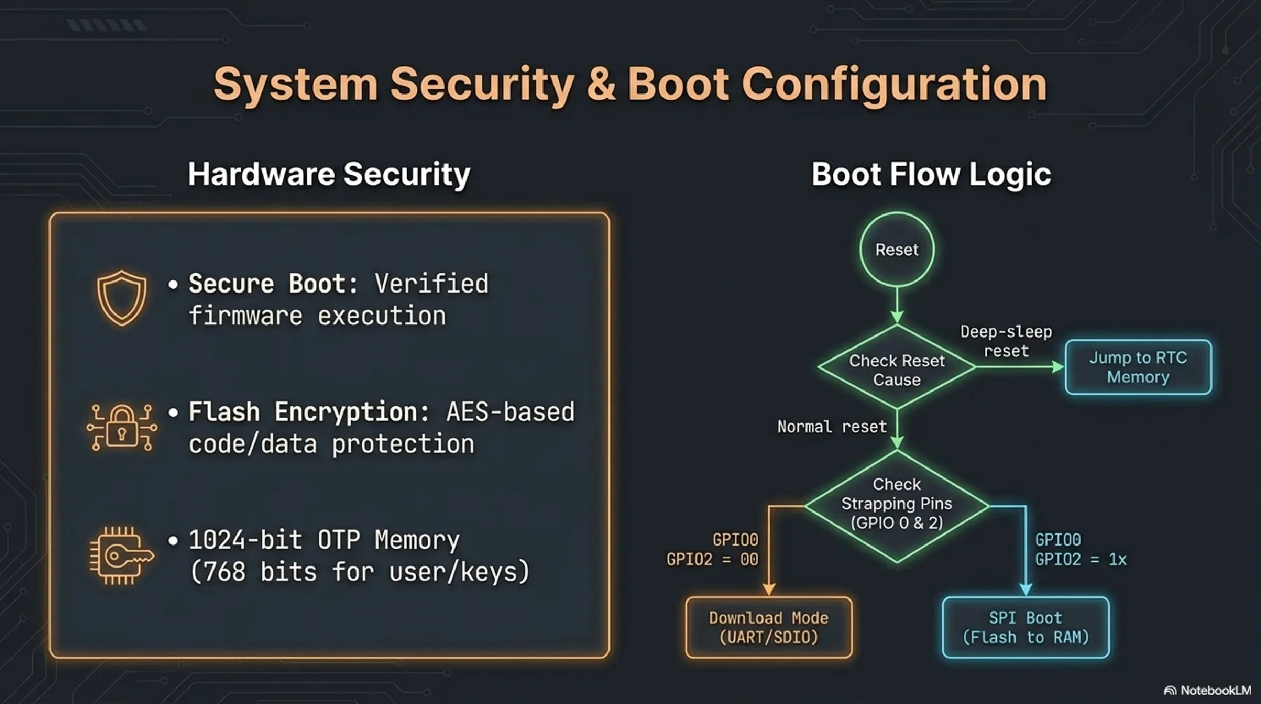
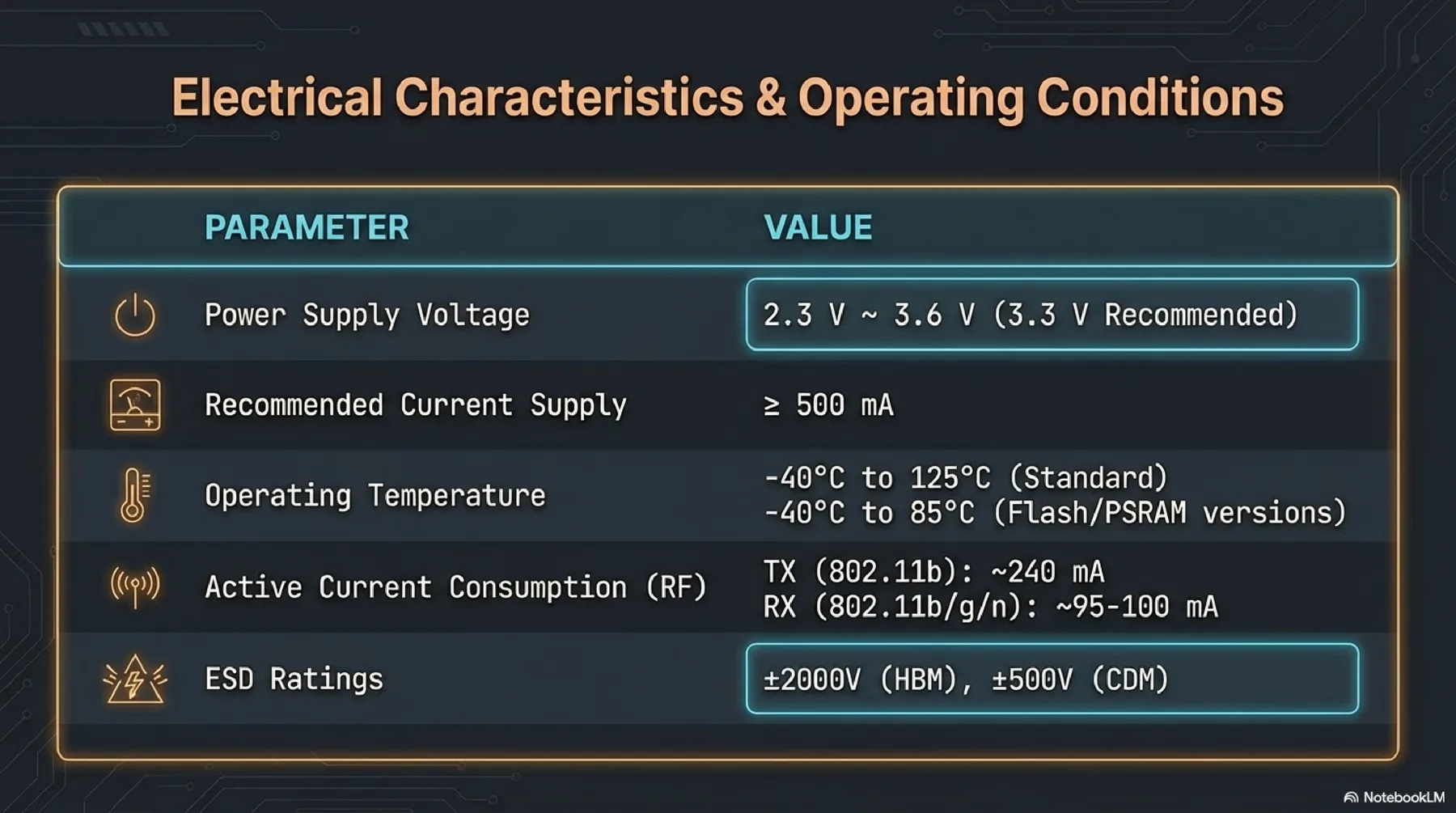
ESP32 combines microcontroller capabilities with built-in Wi-Fi and Bluetooth, making it highly suitable for connected devices. The datasheet covers architecture variants, security features, pin/boot behavior, and low-power states.
More detailed presentation about selected microcontroller (ESP32)
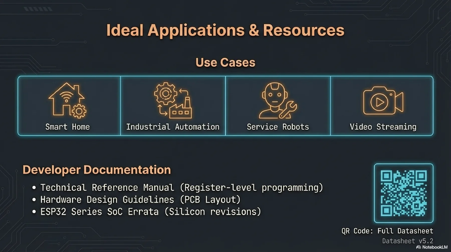
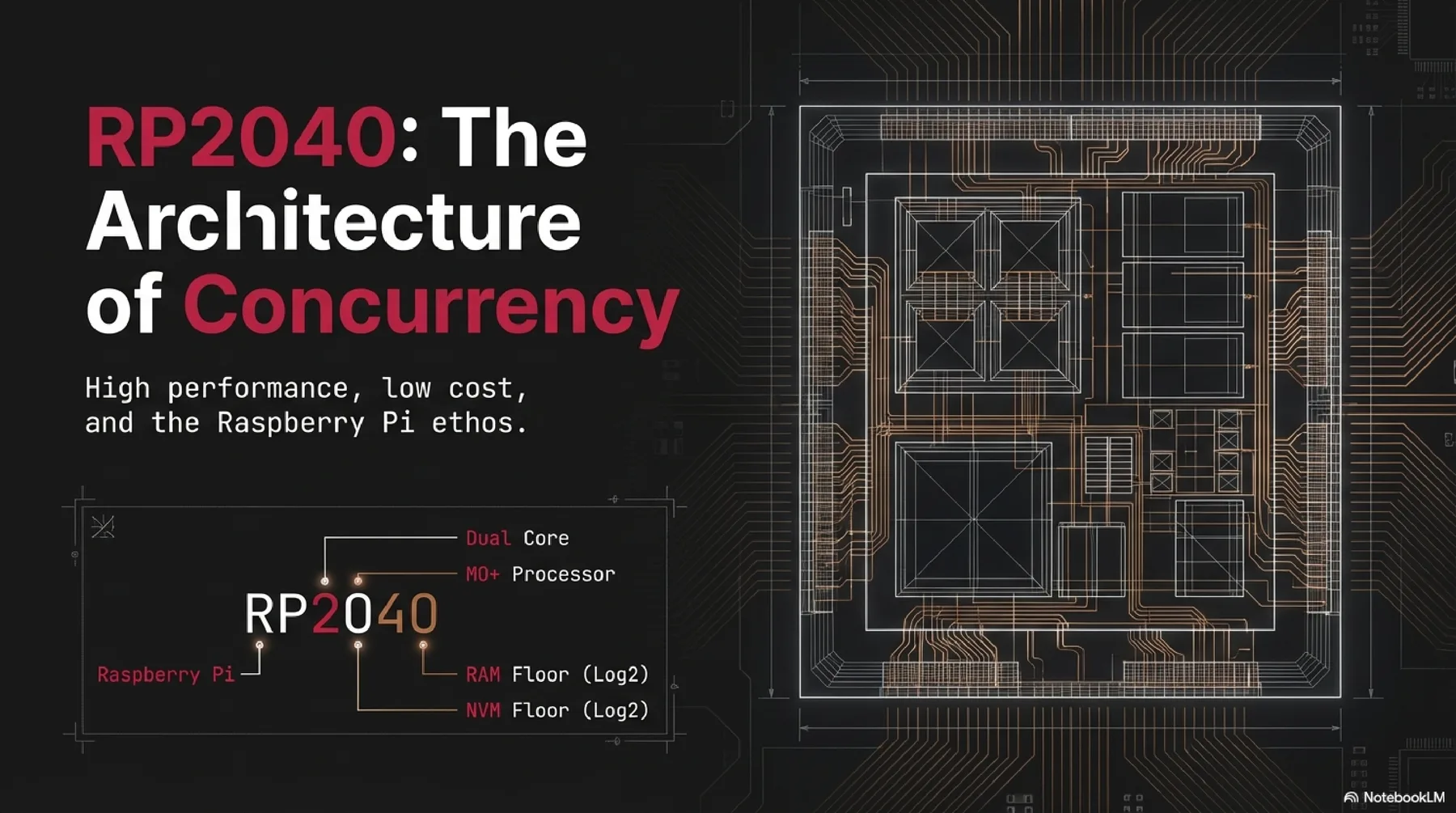
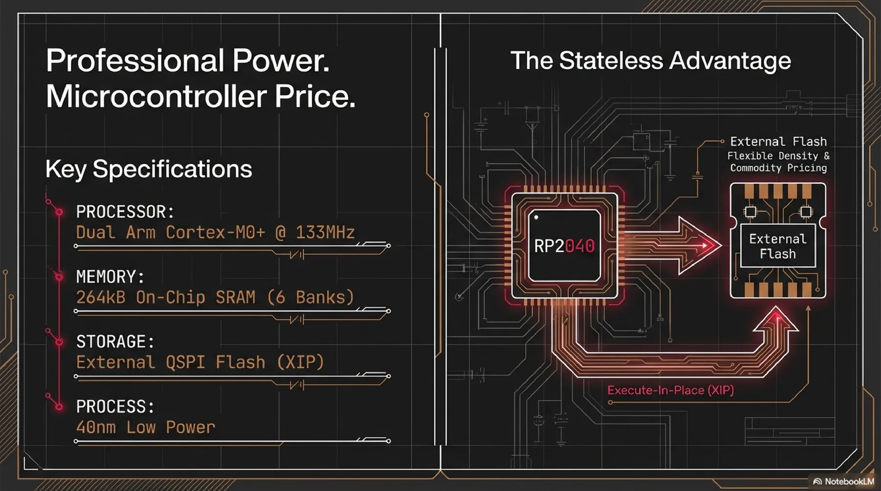
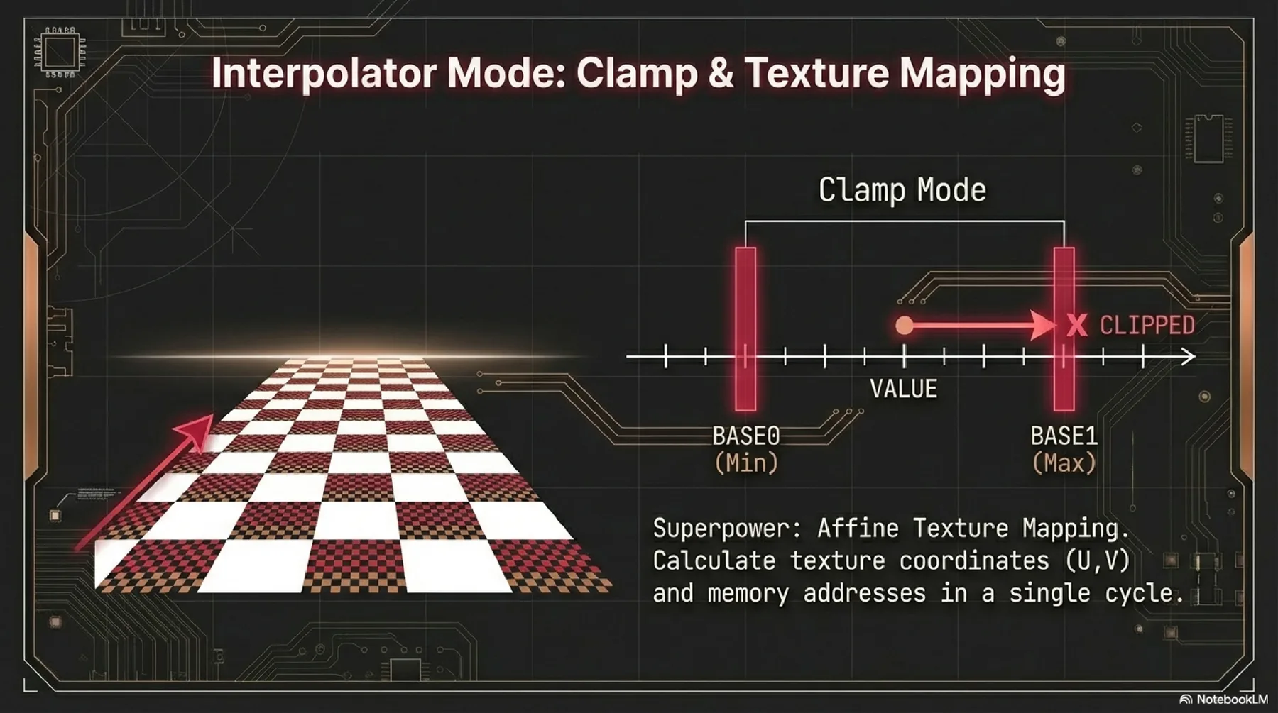
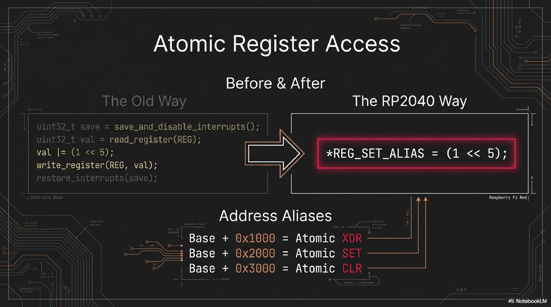
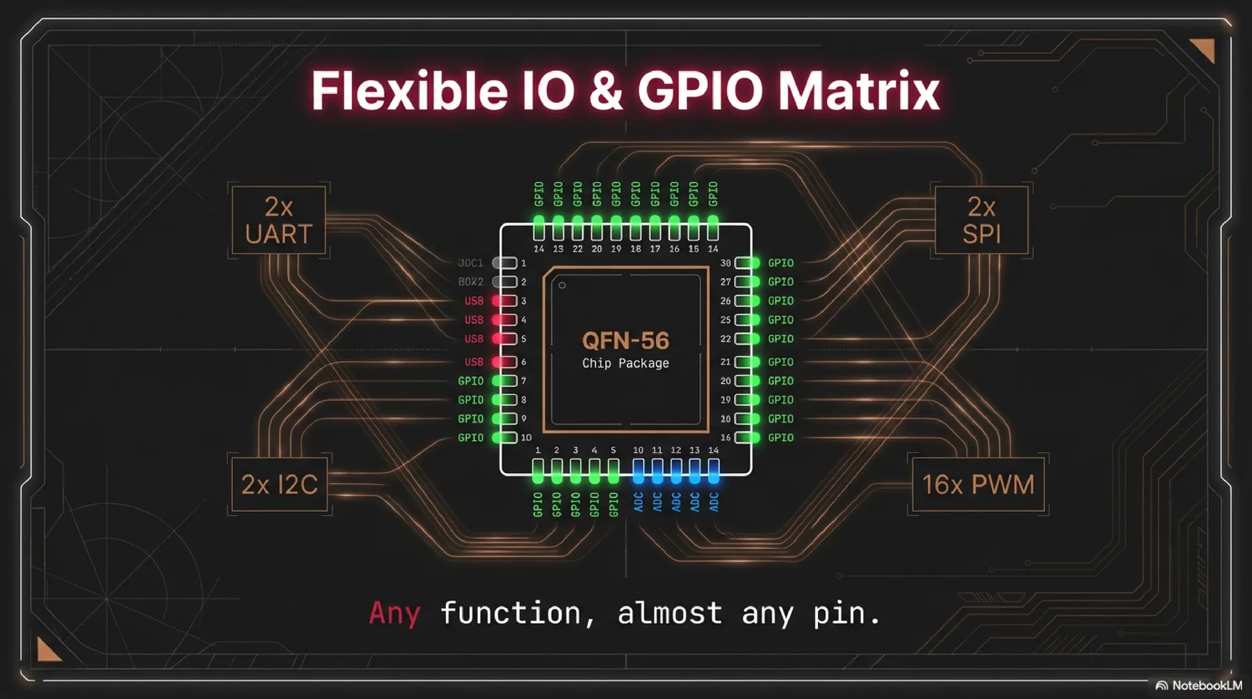
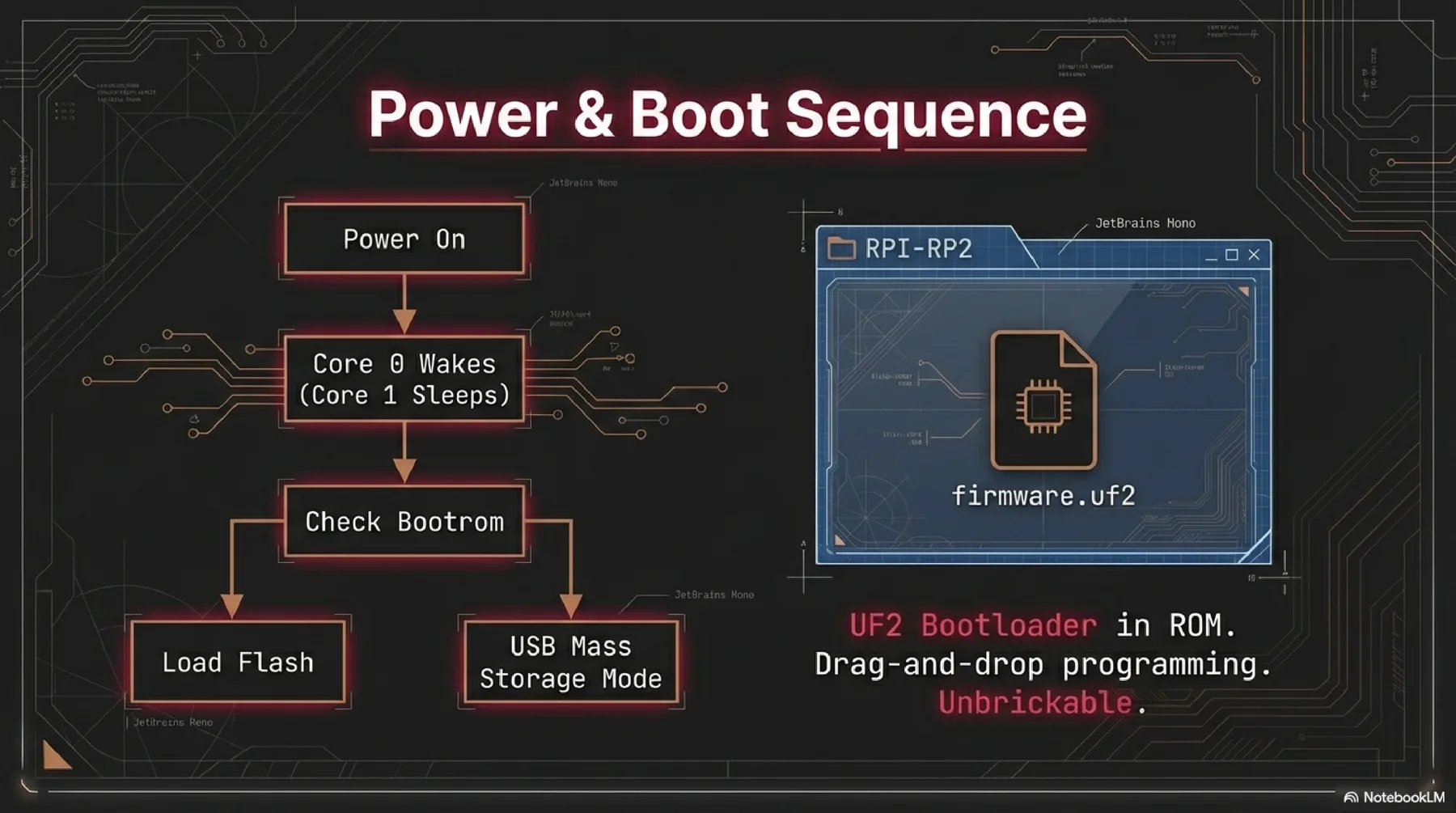
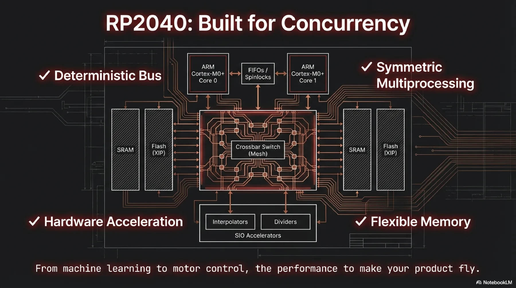
RP2040
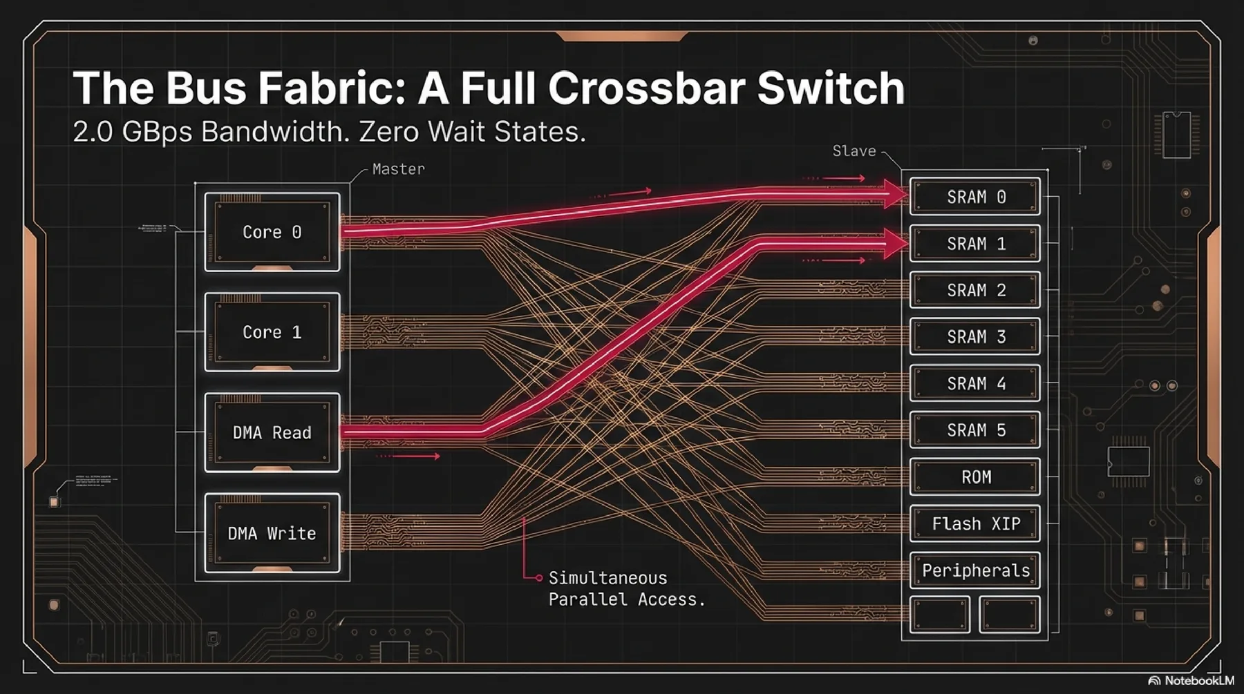
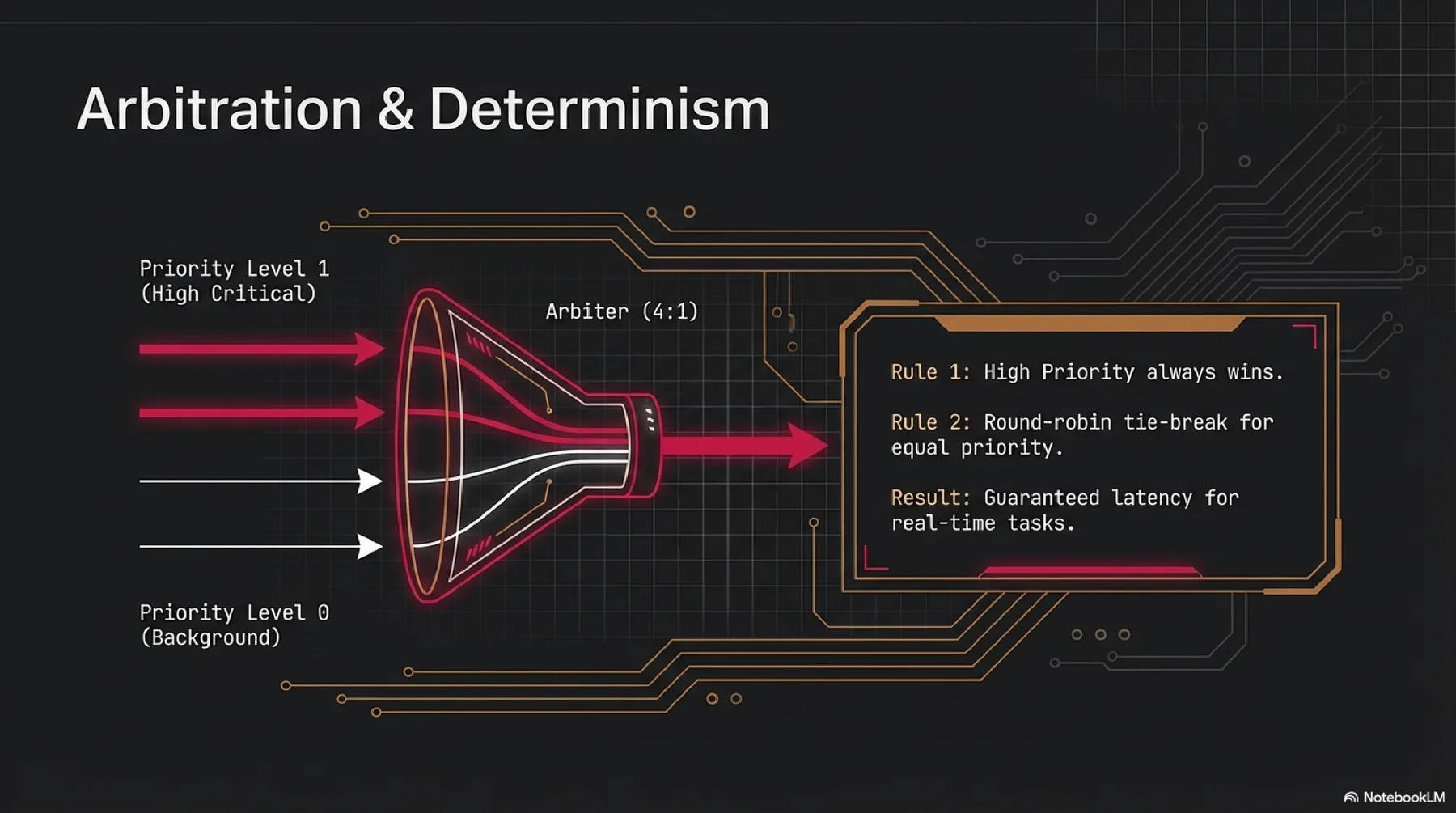
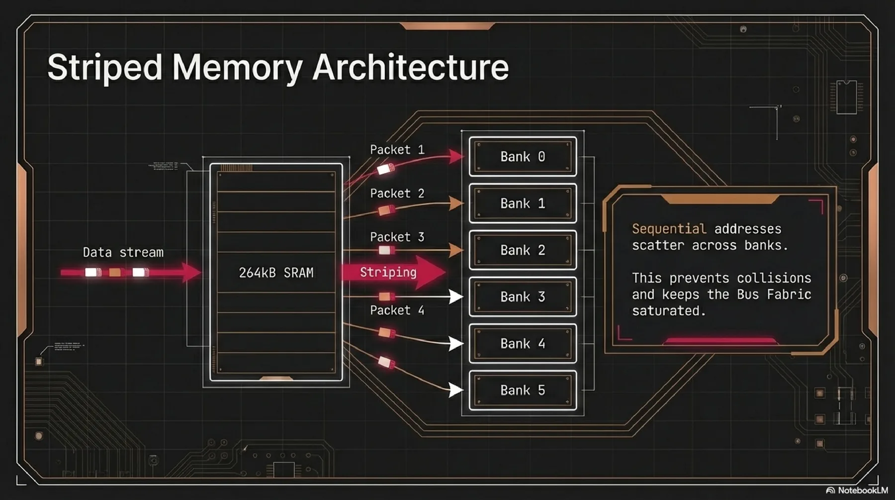
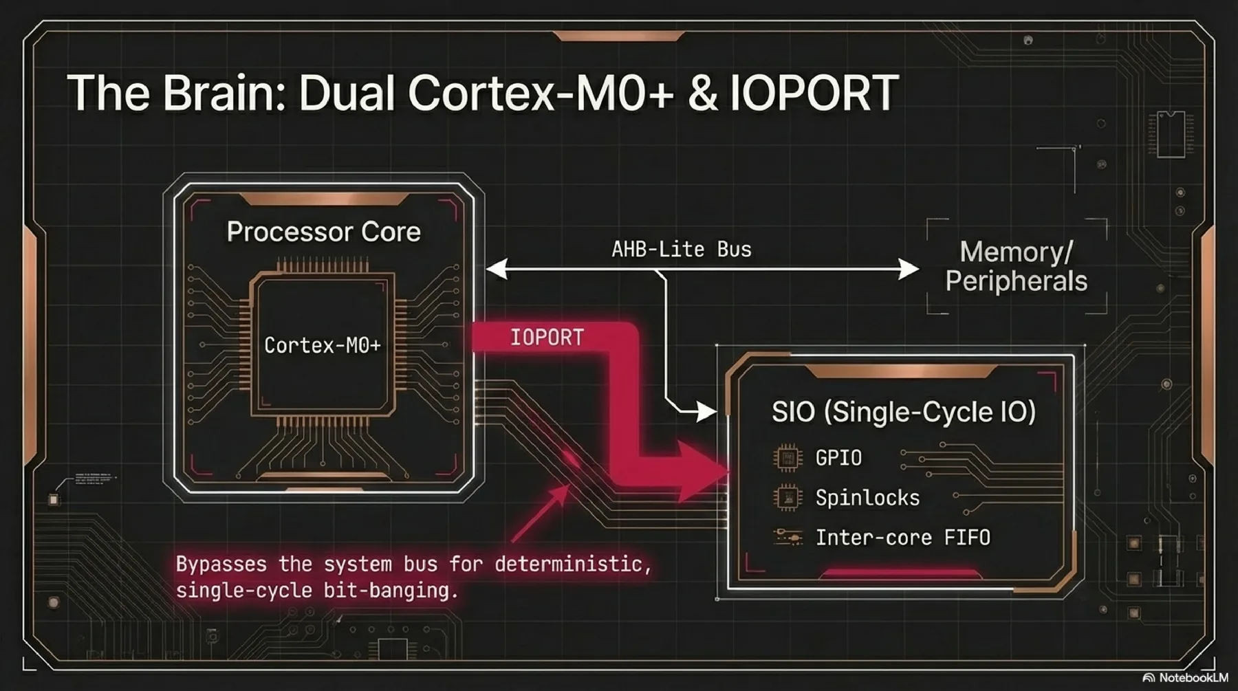
RP2040 features dual Cortex-M0+ cores, 264 KB SRAM, and flexible PIO blocks for custom hardware interfaces. It provides a powerful but approachable environment for parallel control and rapid prototyping.
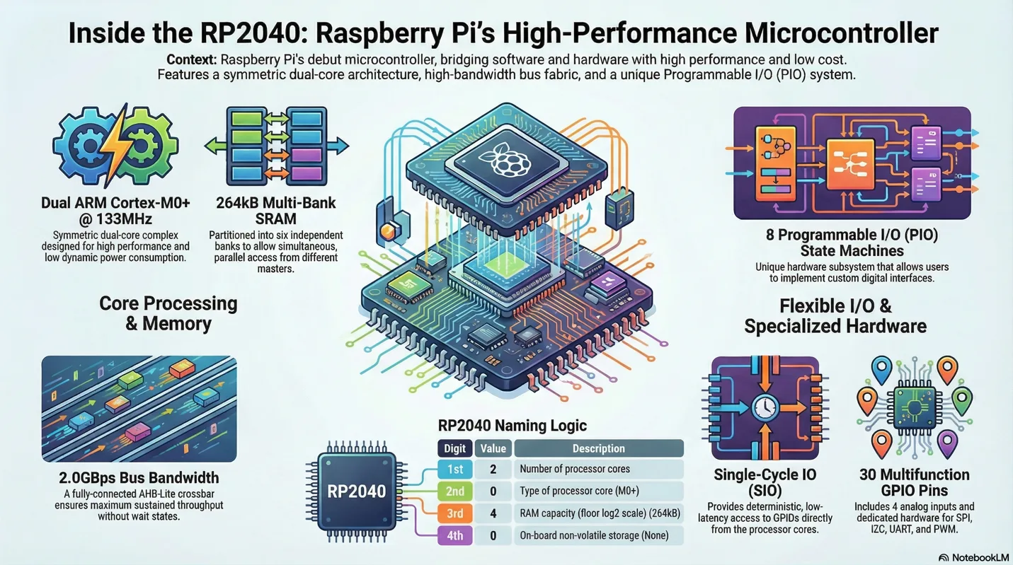
More detailed presentation about selected microcontroller (Raspberry Pi RP2040)
Practical Programming and Board Testing
For the second part of Week 4, I moved from datasheet research into hands-on programming and testing with real boards and emulation. I kept the cleaned source notes in week04-part2.md.
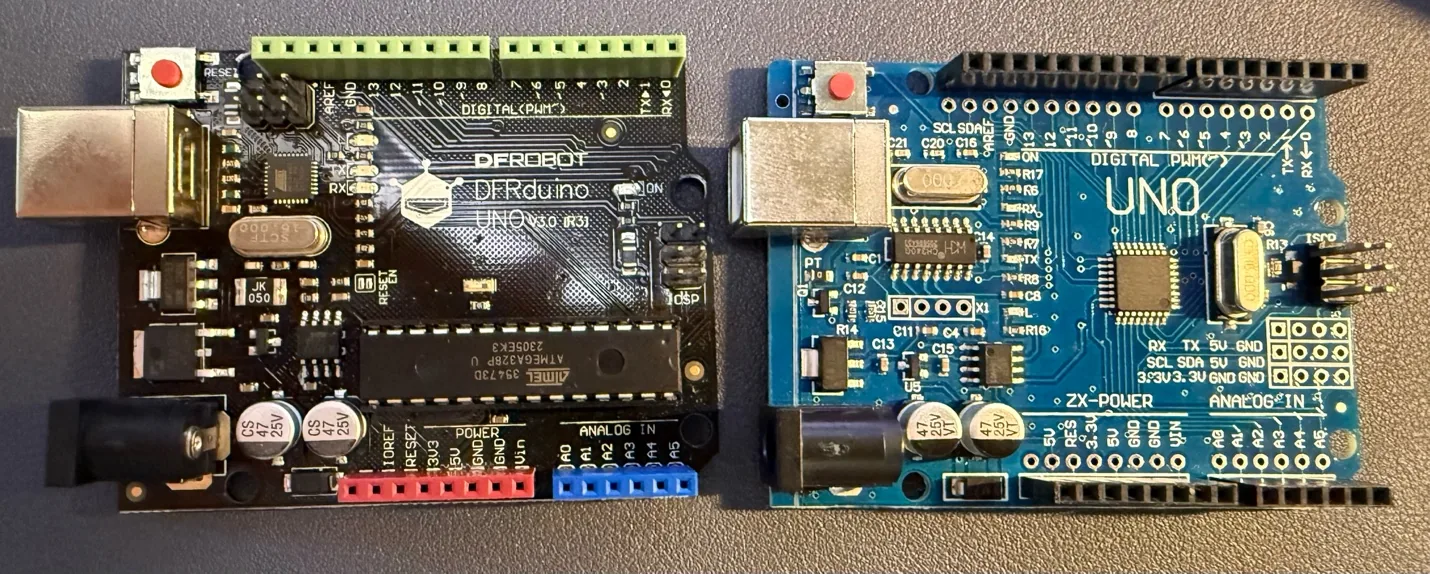
Arduino Uno R3
I started with the Arduino Uno R3, a classic board built around the ATmega328P chip. Since I am already more familiar with the Arduino ecosystem, it was a good place to refresh the basics before moving to the XIAO ESP32C3.
Because so many projects and extensions exist for the Arduino Uno, I first reviewed the board layout and pin configuration.
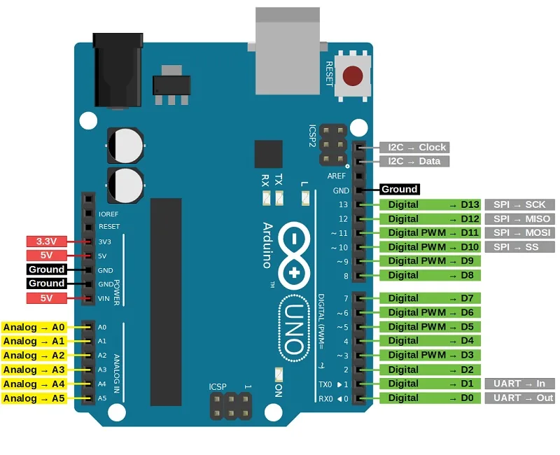
Official reference: Arduino Uno R3 documentation.
Arduino IDE
For the Arduino family, many IDEs can be used, but the native Arduino IDE is the most direct place to start. I reviewed the main parts of the interface before testing the board.
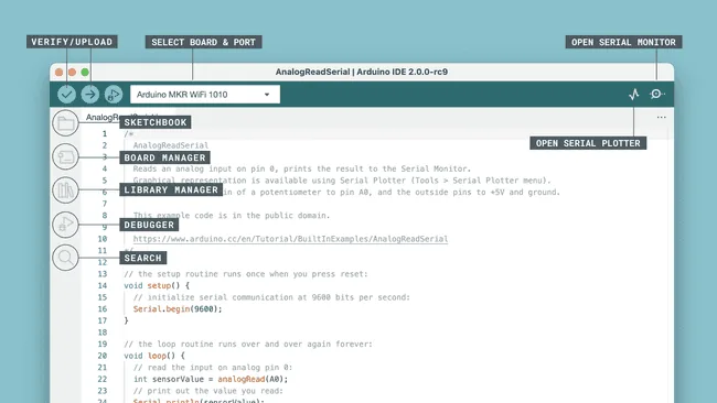
- Verify / Upload: checks the sketch and uploads it to the selected board.
- Select Board & Port: chooses the board type and the serial port.
- Serial Monitor: shows live text data from the board.
- Sketchbook: organizes saved Arduino projects.
- Board Manager: installs support packages for different boards.
- Library Manager: installs and updates code libraries.
- Debugger: inspects a running program on supported boards.
- Search: quickly finds text or code in the sketch.
- Serial Plotter: displays incoming serial data as a live graph.
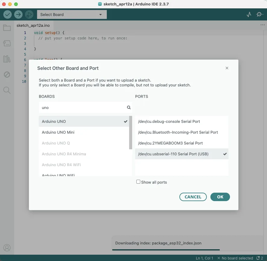
To begin, I selected the Arduino Uno board and the correct port, usually the USB serial connection.
Blinking LED
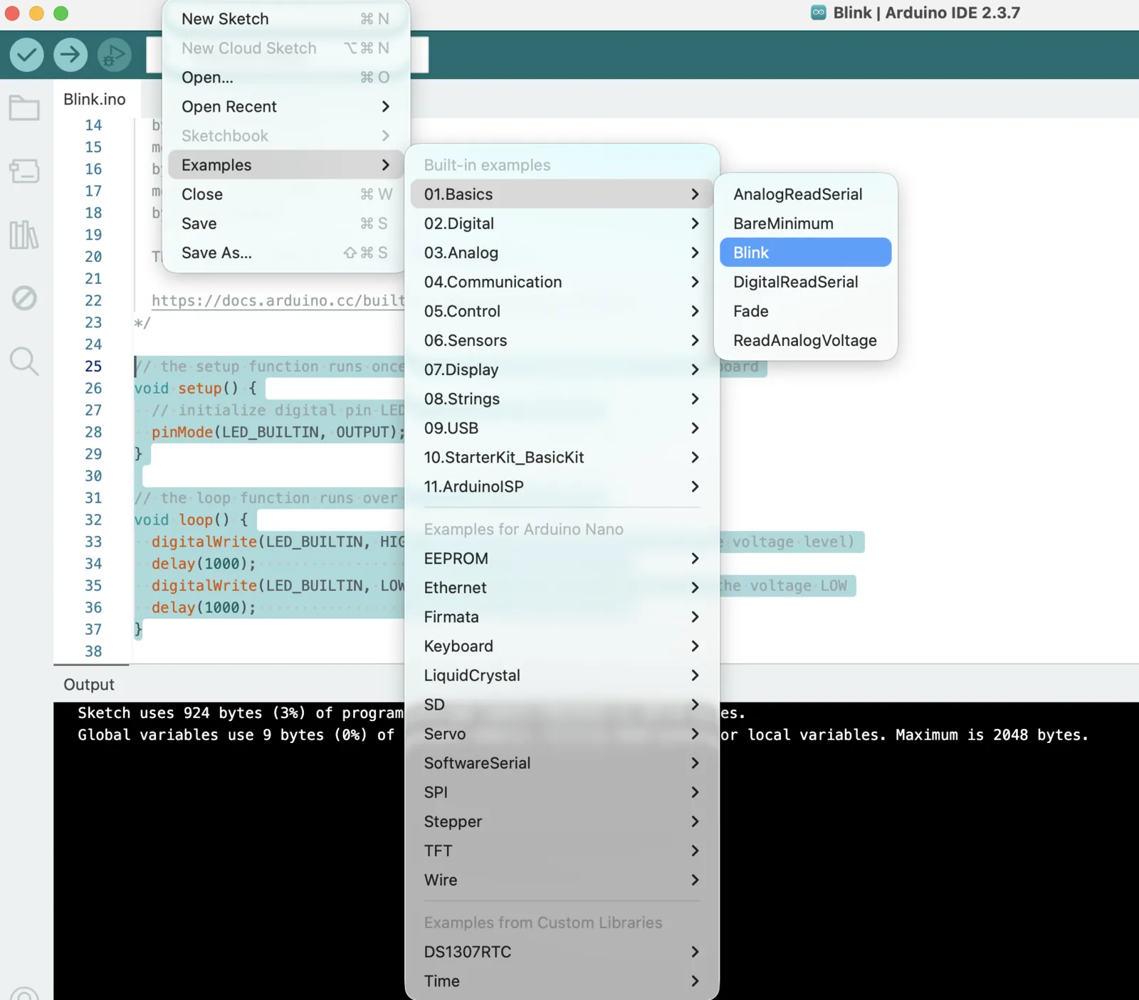
As suggested in many beginner workflows, I started with a simple blink sketch to confirm that the board and upload flow were working correctly.
Code - Arduino Uno blink test
// the setup function runs once when you press reset or power the board
void setup() {
  // initialize digital pin LED_BUILTIN as an output.
  pinMode(LED_BUILTIN, OUTPUT);
}

// the loop function runs over and over again forever
void loop() {
  digitalWrite(LED_BUILTIN, HIGH);  // turn the LED on
  delay(1000);                      // wait for a second
  digitalWrite(LED_BUILTIN, LOW);   // turn the LED off
  delay(1000);                      // wait for a second
}
As a result, the built-in LED blinked correctly on the real board.
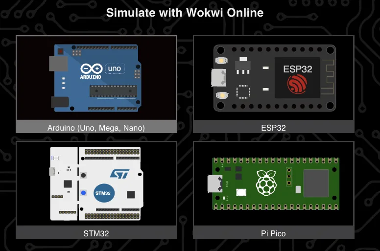
Wokwi Emulation
For Arduino and several other boards, it is also possible to use emulation in Wokwi. I uploaded the same blink sketch to compare the virtual and physical workflows.
Emulator: wokwi.com.
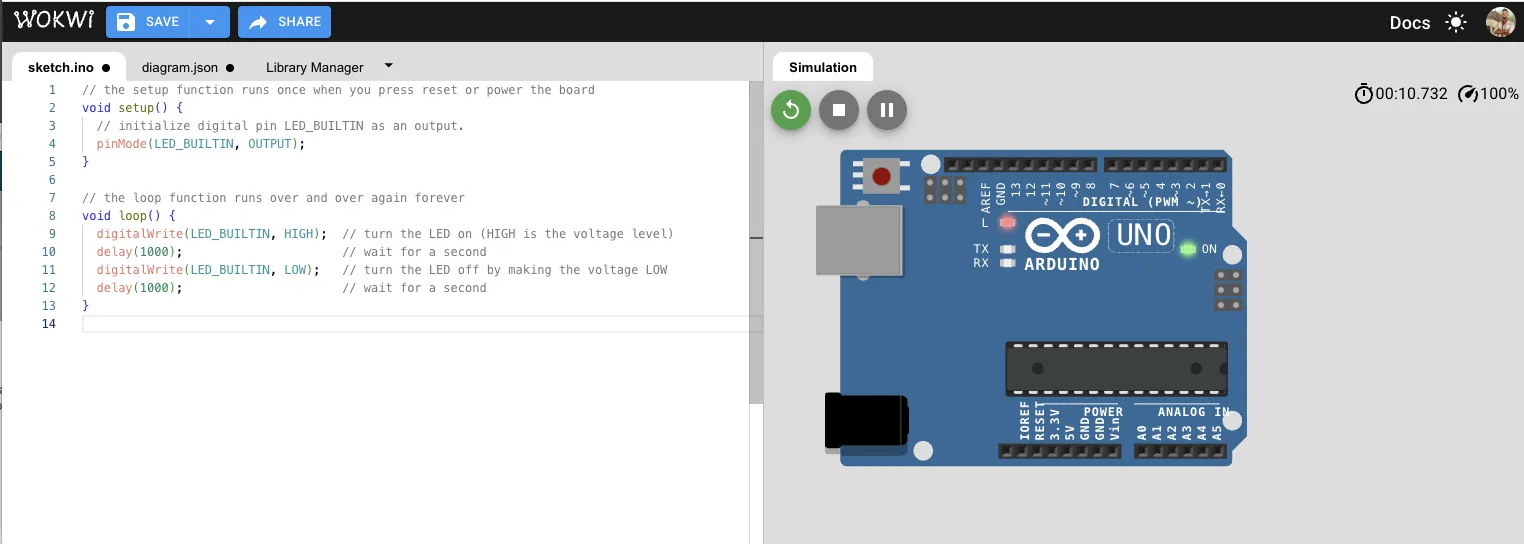
The emulated result matched the real board test, so the built-in LED blinked correctly in both environments.
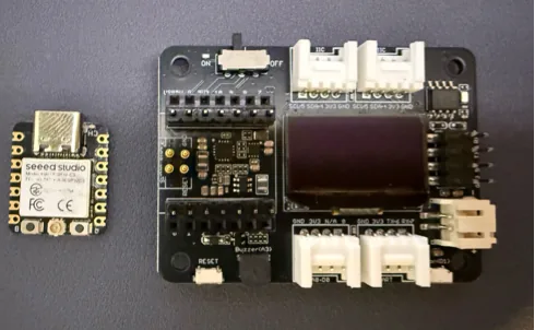
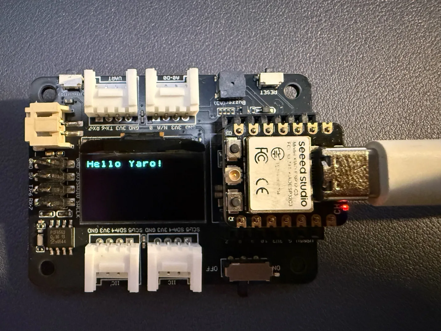
Seeed XIAO ESP32C3 + Expansion Board
After the Arduino Uno tests, I moved to the Seeed XIAO ESP32C3 together with the expansion board.
Official references: XIAO ESP32C3 getting started and XIAO Expansion Board.
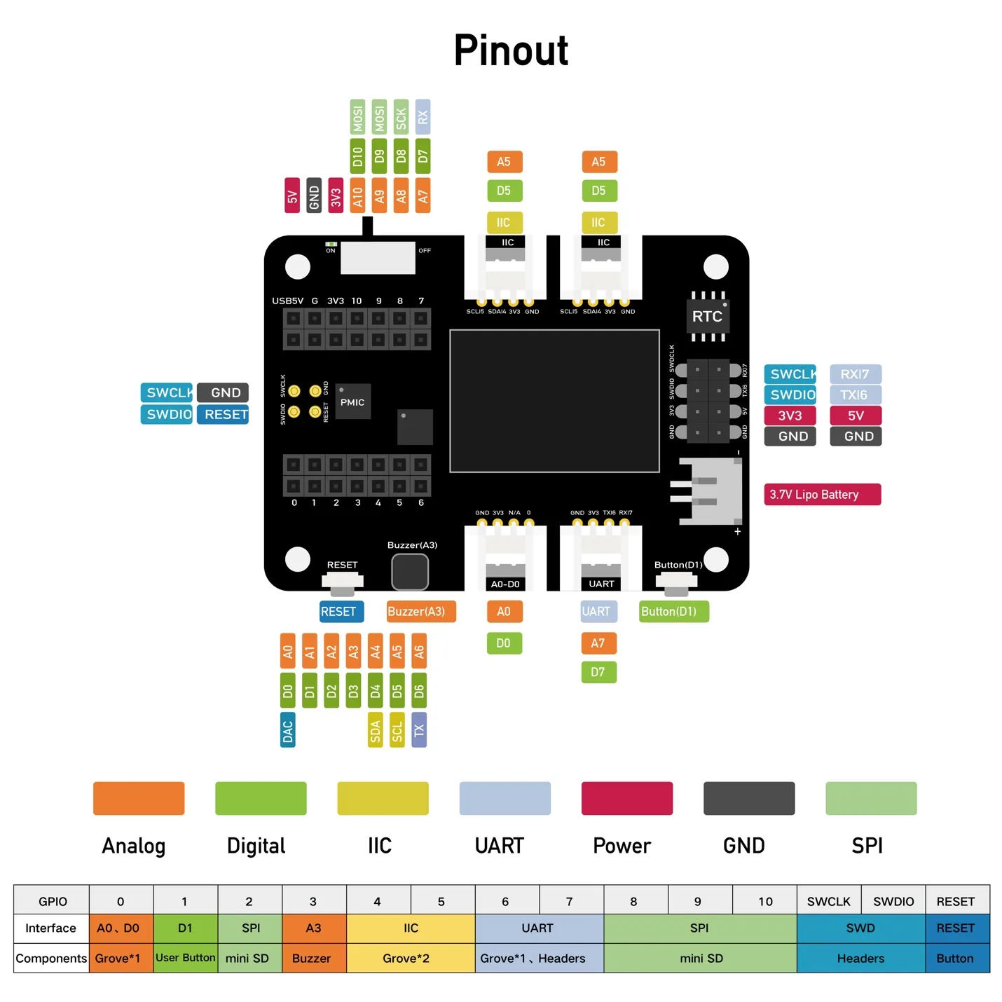
Hardware Overview
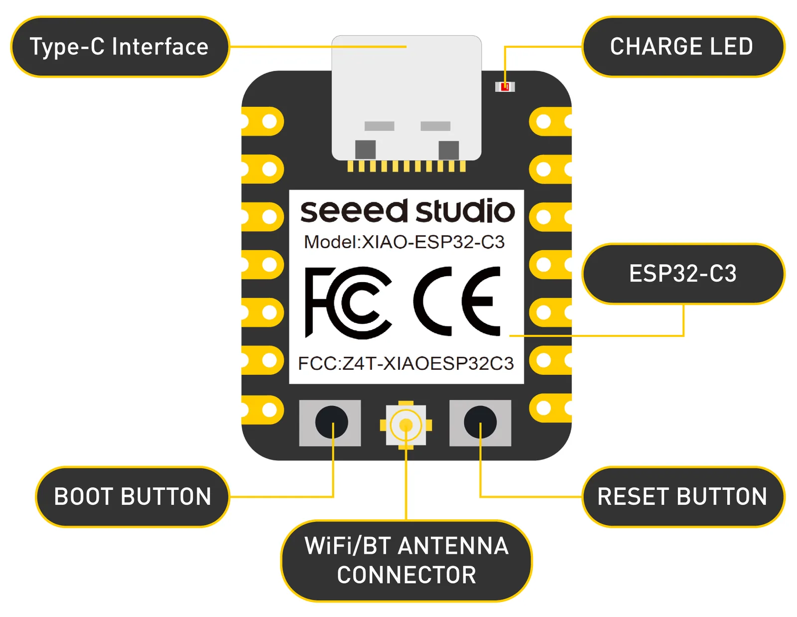
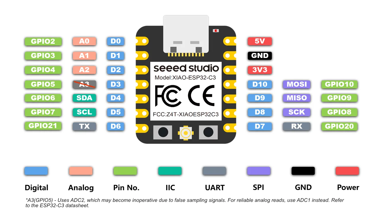
I noted the most important power pins first:
- 5V: 5V output from the USB port, or protected external input.
- 3V3: regulated output from the onboard regulator.
- GND: common ground for power, data, and signal.
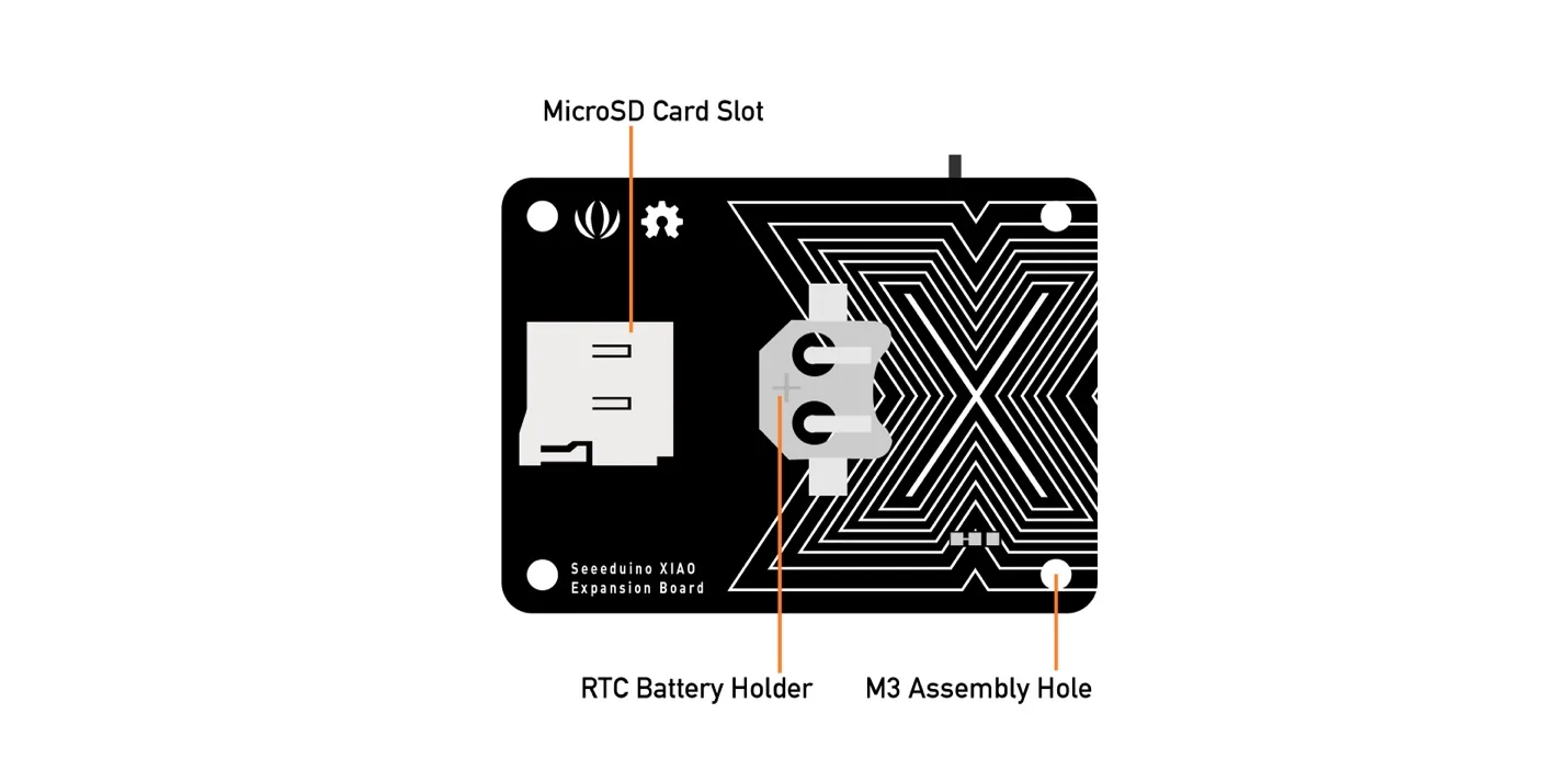
Expansion Board
The expansion board adds several useful peripherals and makes quick prototyping easier.
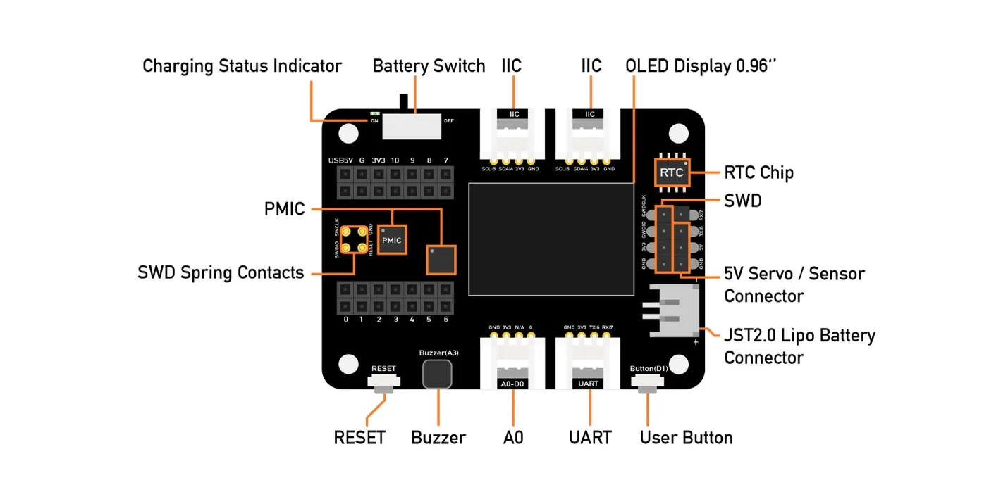
The board includes an external MicroSD card slot and an RTC battery holder. The MicroSD card adds storage, and the RTC helps maintain time when the main power is off.
Main expansion board specifications:
- Operating voltage: 5V / 3.7V lithium battery
- Charging current: 460 mA max
- RTC timer precision: +/- 1.5 s/day at 25 C
- RTC battery: CR1220
- Display: 0.96 inch OLED
- Expandable memory: MicroSD card
- Grove interface: Grove I2C x2, Grove UART x1, A0/D0 Grove x1
- Other external equipment: passive buzzer, user button, 5V servo connector
The expansion board includes an OLED display, reset button, SWD debug pins, high-precision RTC, MicroSD slot, user button, passive buzzer, Grove connectors, LiPo charging support, and a 5V servo connector.
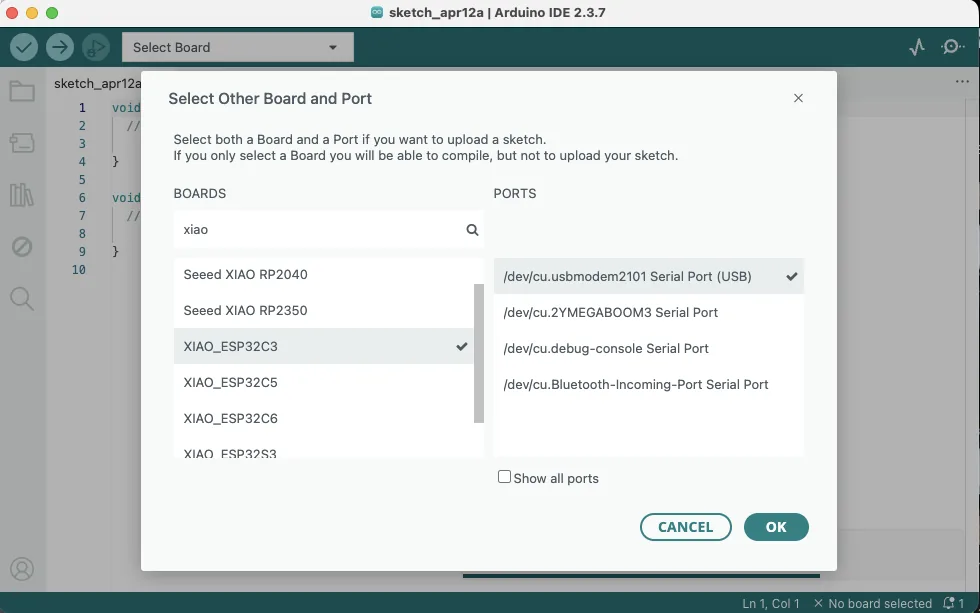
Board Programming
For the XIAO ESP32C3, I still used the Arduino IDE, but I needed to install and select the correct XIAO board package and choose the correct port.
After the board was recognized, I tested the OLED display using the official example and installed the
U8g2 library through the Arduino Library Manager.
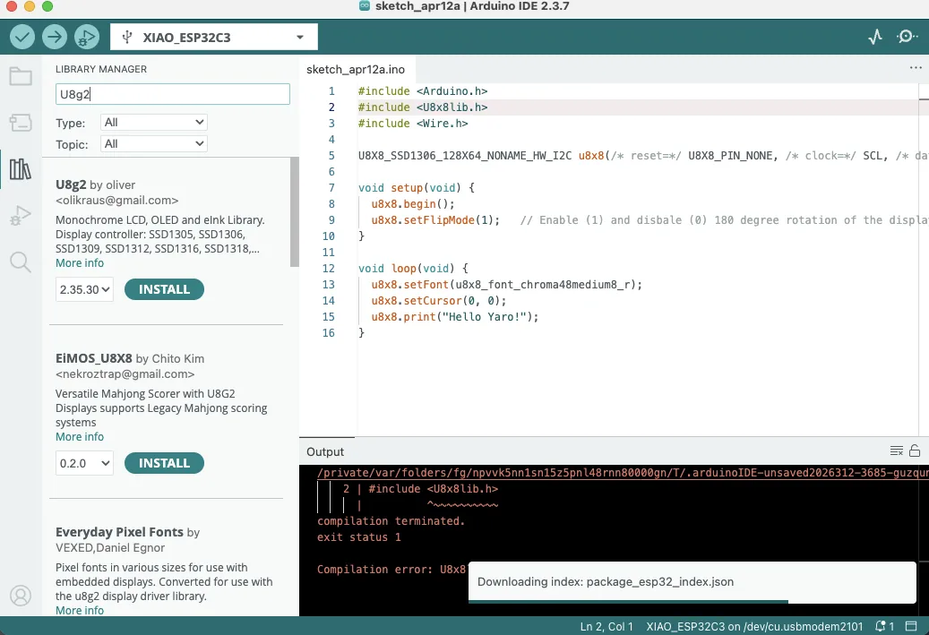
Code - XIAO OLED hello-world test
#include <Arduino.h>
#include <U8x8lib.h>
#include <Wire.h>

U8X8_SSD1306_128X64_NONAME_HW_I2C u8x8(
  /* reset = */ U8X8_PIN_NONE,
  /* clock = */ SCL,
  /* data = */ SDA
);

void setup(void) {
  u8x8.begin();
  u8x8.setFlipMode(1);  // enable 180 degree rotation
}

void loop(void) {
  u8x8.setFont(u8x8_font_chroma48medium8_r);
  u8x8.setCursor(0, 0);
  u8x8.print("Hello Yaro!");
}
OLED + RGB LED Experiment
Next, I asked AI to extend the test so that a 30-LED strip would show a moving light effect while the OLED
screen displayed a simple animated spaceship scene. For this, I also installed the
Adafruit NeoPixel library.
I have 30 LED, not 8, and make some like running or some very cool effects with this LED, like gradation or some like running or cycling. Maybe several will be cool. And add some interesting graphics to the screen for testing purposesCode - XIAO OLED and 30-LED RGB animation test
#include <Arduino.h>
#include <Wire.h>
#include <U8g2lib.h>
#include <Adafruit_NeoPixel.h>

#define LED_PIN   D0
#define LED_COUNT 30

U8G2_SSD1306_128X64_NONAME_F_HW_I2C u8g2(U8G2_R0, U8X8_PIN_NONE);
Adafruit_NeoPixel strip(LED_COUNT, LED_PIN, NEO_GRB + NEO_KHZ800);

int shipX = 10;
int dir = 1;
int ledHead = 0;

void drawShipScene() {
  u8g2.clearBuffer();

  for (int i = 0; i < 20; i++) {
    int x = (i * 23 + millis() / 10) % 128;
    int y = (i * 13 + millis() / 20) % 64;
    u8g2.drawPixel(x, y);
  }

  u8g2.setFont(u8g2_font_6x12_tf);
  u8g2.drawStr(18, 10, "OLED + RGB TEST");

  u8g2.drawTriangle(shipX, 50, shipX + 12, 50, shipX + 6, 38);
  u8g2.drawPixel(shipX + 4, 52);
  u8g2.drawPixel(shipX + 8, 52);

  u8g2.sendBuffer();
}

void updateLEDs() {
  strip.clear();

  for (int t = 0; t < 8; t++) {
    int p = ledHead - t;
    if (p >= 0 && p < LED_COUNT) {
      int b = 255 - t * 30;
      if (b < 0) b = 0;
      strip.setPixelColor(p, strip.Color(0, 0, b));
    }
  }

  strip.setPixelColor((ledHead + 10) % LED_COUNT, strip.Color(0, 150, 0));
  strip.setPixelColor((ledHead + 20) % LED_COUNT, strip.Color(150, 0, 0));
  strip.show();

  ledHead++;
  if (ledHead >= LED_COUNT + 8) ledHead = 0;
}

void setup() {
  u8g2.begin();
  strip.begin();
  strip.setBrightness(80);
  strip.clear();
  strip.show();
}

void loop() {
  shipX += dir;
  if (shipX < 5 || shipX > 110) dir = -dir;

  drawShipScene();
  updateLEDs();

  delay(60);
}
This program uses the OLED screen and the RGB LED strip together. The screen shows a small moving spaceship with stars in the background, while the LED strip displays moving colored lights.
drawShipScene(): clears the OLED screen, draws moving stars, writes the title, and draws the spaceship.updateLEDs(): creates a moving light effect with blue, green, and red LEDs.setup(): starts the OLED display and LED strip, sets brightness, and clears the strip.loop(): moves the spaceship, changes direction at the edges, and refreshes both outputs.
Important variables:
LED_PIN: the pin connected to the LED strip.LED_COUNT: the number of LEDs in the strip.shipX: the horizontal position of the spaceship.dir: the movement direction of the spaceship.ledHead: the moving position of the LED light effect.
As a result, the OLED screen displayed simple moving graphics and the LED strip showed a moving multicolor light effect.
Reflection
This week, as part of Week 4 of Fab Academy, I explored different embedded systems and microcontrollers in both virtual and real programming environments. I worked with Arduino Uno in simulation and in real hardware, and I also programmed the Seeed Studio XIAO ESP32C3. This helped me understand the difference between testing code virtually and applying it to actual physical devices.
During this week, I connected and programmed several components, including an RGB LED strip and the display on the XIAO expansion board. I also used AI to help me write code, improve it, and understand it better. This was especially useful while learning something new, because it helped me break the code into smaller parts and understand what each function was doing. With this support, I was able to make the code easier to follow and more structured.
This week showed me that embedded programming is not only about writing code, but also about understanding how software interacts with hardware. I had to solve practical problems, test different ideas, and learn through experimentation. Using AI as a support tool made this process more effective because it helped me understand the logic behind the code rather than only copying it.
References
- Arduino source file:
xiao_oled_rgb_experiment.ino - Zequan Lin - Week 4 group assignment reference
- Winnie Sun - Week 4 group assignment reference