Week 16 — System Integration
Group assignment
- There was no group assignment for this week.
Individual assignment
- Design and document the system integration for your final project.
Learning outcomes
- Define and apply system integration to your final project.
Checklist
- Made a plan for system integration for your final project.
- Documented the plan with CAD and/or sketches for system integration.
- Implemented methods of packaging.
- Designed the final project to look like a finished product.
- Documented system integration of the final project.
- Linked to system integration documentation from the final project page.
Documentation
This week I integrated the main parts of Seebscribe into a wearable system. The device needs to sense a heartbeat from the chest, process the signal with a XIAO microcontroller, run from a small LiPo battery, and remain mechanically attached to an elastic strap. The integration work therefore had to solve electrical connections, body contact, component placement, power, and packaging at the same time.
System integration plan
My plan was to divide the wearable into five connected parts:
- Heartbeat input: the AD8232 board reads the electrical signal from two metal snap electrodes touching the chest.
- Controller: a XIAO ESP32-C3 receives the sensor output and provides USB programming and wireless communication.
- Carrier board: a custom milled PCB mechanically holds the controller and sensor while routing signal, power, and ground.
- Power: a compact 3.7 V LiPo battery makes the prototype portable and removes the need for a USB cable while worn.
- Packaging: a rounded 3D-printed tray aligns the sensor, controller, battery, and snap positions along the elastic chest strap.
I first developed and tested the electronics as separate modules. I then measured the physical parts and snap fasteners, arranged them along the strap, and designed the enclosure around the real component dimensions. Keeping the USB port accessible and keeping the sensor connections short were important constraints.
System diagram
This diagram was created during the broader development of the Seebscribe concept. It helped me plan the relationship between the wearable sensor, wireless communication, and possible display outputs.
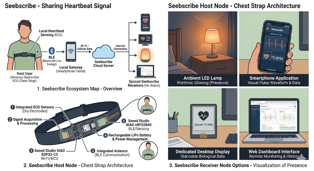
This is an early system concept. The completed Week 16 prototype follows this implemented path: chest electrodes → AD8232 ECG sensor → XIAO ESP32-C3 → Wi-Fi → live browser dashboard. BLE, the nRF52840, cloud communication, lamps, and separate receiver devices remain possible future developments and are not part of the current integrated prototype.
For generating this system diagram image, I used ChatGPT. This is the prompt I used to create the AI-generated engineering infographic:
Create a clean, modern engineering infographic in a flat vector style with subtle 3D shading, suitable for an academic engineering report. The infographic should explain the architecture of a wearable IoT heartbeat-sharing system called Seebscribe. Use a white background, a minimal color palette, professional typography, and a balanced layout divided into three main sections. In the first section, illustrate a person wearing a soft ECG chest strap that measures the user’s heartbeat using ECG electrodes and transmits the data via Wi-Fi (not Bluetooth) to the Seebscribe Cloud Server. The cloud server synchronizes the heartbeat information with three receiver devices: a smartphone application, a heart-shaped ambient LED lamp, and a web dashboard. Show the data flow as ECG Chest Strap → Wi-Fi → Seebscribe Cloud Server → Smartphone App + Ambient Heart Lamp + Web Dashboard, and do not include Bluetooth or BLE icons anywhere in the diagram. In the second section, present a simplified internal view of the wearable chest strap showing only the actual electronics used in the project. Include an ECG sensor with dry electrodes, a single ESP32-C3 microcontroller, and a rechargeable LiPo battery. Remove any NRF chips, secondary microcontrollers, BLE modules, antennas, or other unidentified electronic components. Label the three components as ECG Sensor (Dry Electrodes), ESP32-C3 (Wi-Fi MCU), and Rechargeable LiPo Battery, emphasizing that the device uses a simple single-board architecture. In the third section, illustrate the three synchronized receiver devices. The first should be a glowing heart-shaped ambient LED lamp made from soft translucent white fabric and illuminated internally by a warm red LED, closely resembling a handmade fabric heart sculpture. The second should be a smartphone displaying a live ECG waveform together with the current heart rate in beats per minute. The third should be a laptop showing a web dashboard with real-time ECG monitoring, historical data, and heart rate information. Do not include a dedicated desktop display, smartwatch, or any additional receiver devices. At the bottom of the infographic, include a simplified architecture diagram showing the communication flow as ECG Chest Strap (ESP32-C3) → Wi-Fi → Seebscribe Cloud Server → Receiver Devices (Heart Lamp, Smartphone, Web Dashboard). Also include a row of simple engineering icons representing real-time ECG sensing, Wi-Fi connectivity, cloud synchronization, a rechargeable battery, and presence sharing. The overall illustration should have a professional engineering infographic style with clean vector graphics, subtle gradients, consistent iconography, clear labels and callouts, generous spacing, and a polished academic appearance suitable for a Fab Academy final project report. Ensure that every hardware component accurately represents the real implementation of the Seebscribe prototype and do not invent or include any fictional electronics.| System stage | Implemented component or method |
|---|---|
| Body input | Two metal snap electrodes integrated into the elastic chest strap |
| Signal acquisition | AD8232 ECG sensor board |
| Processing | XIAO ESP32-C3 mounted on the custom carrier PCB |
| Power | Internal 3.7 V, 600 mAh LiPo battery |
| Communication | Wi-Fi from the XIAO ESP32-C3 |
| Output | Live ECG and heart-rate dashboard in a web browser |
Electronics and custom carrier board
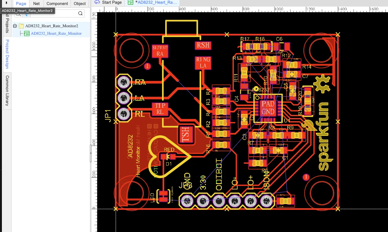
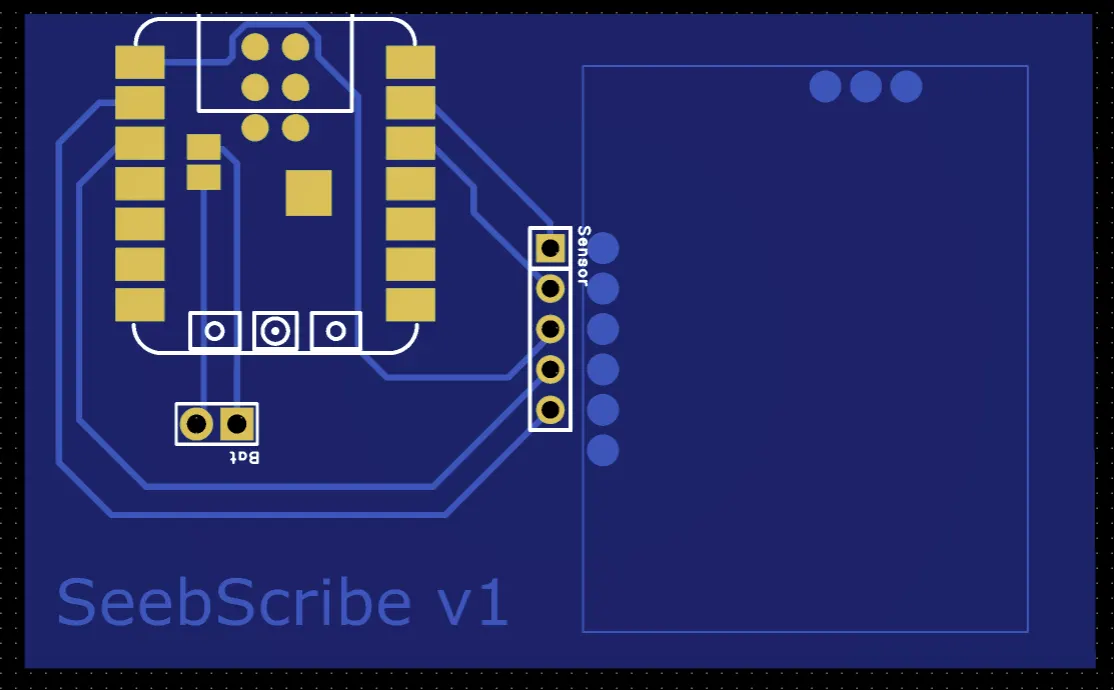
I examined the AD8232 heartbeat-monitor PCB layout to understand its electrode, signal, power, and mounting connections before integrating the module.
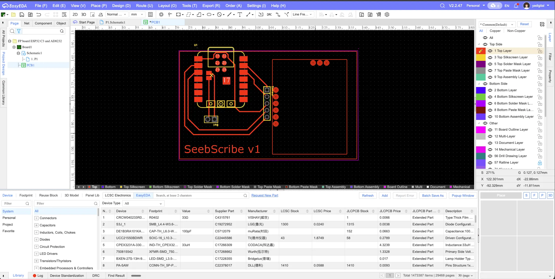
Early EasyEDA carrier-board layout. The XIAO controller is placed beside a reserved sensor area so the two modules can become one compact assembly.
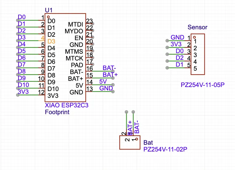
Pin-mapping schematic for the XIAO, five-pin sensor connector, and two-pin battery connector. This defined the electrical interfaces before routing the PCB.
Routed carrier-board view showing the controller footprint, battery connection, sensor header, and reserved module area.
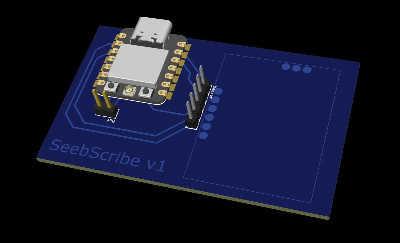
The 3D preview helped me check the controller orientation, USB access, header position, and available space before fabrication.
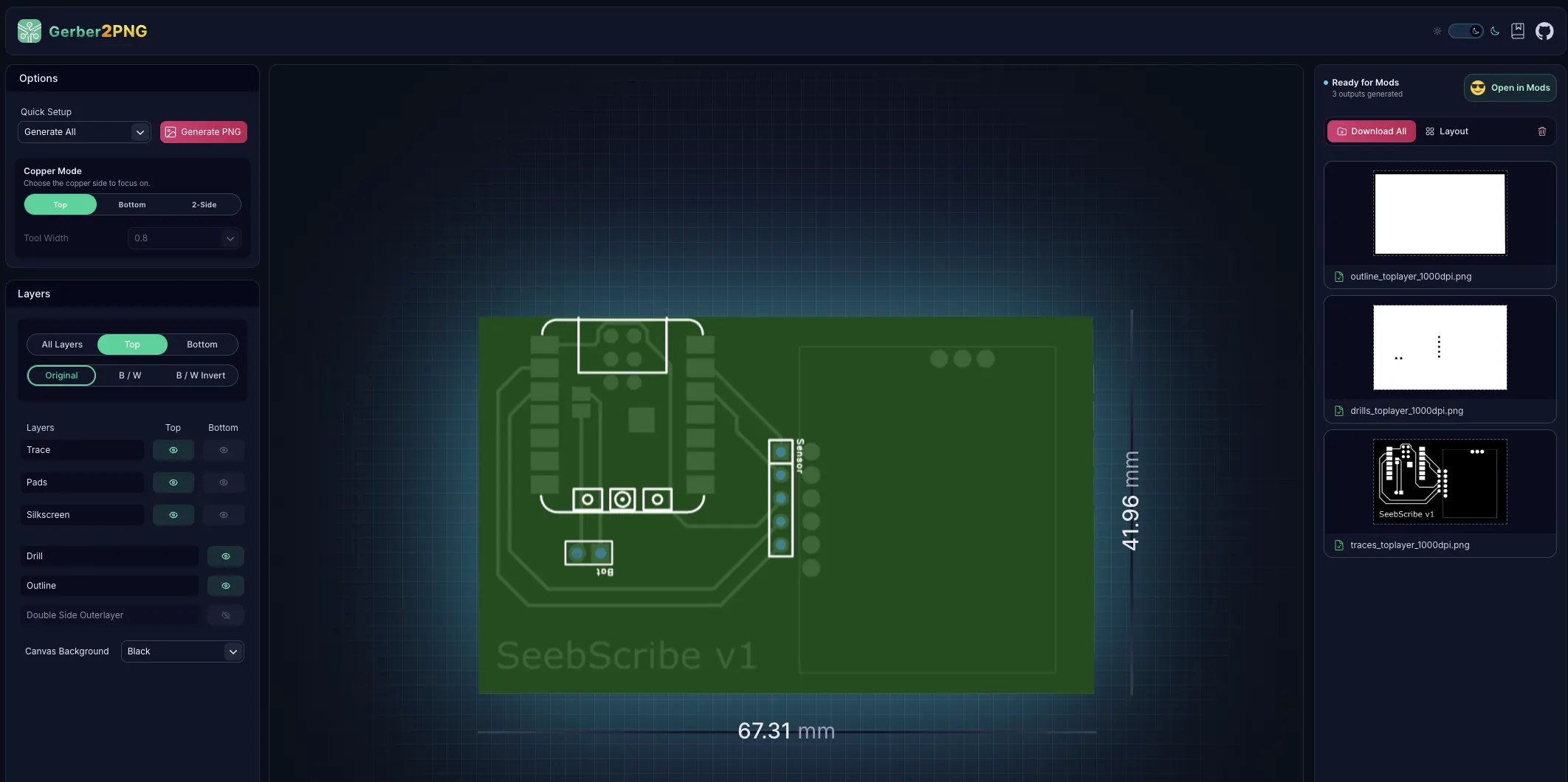
I converted the Gerber layers into trace, drill, and outline images for desktop PCB milling. The board measured approximately 67 × 42 mm at this stage.
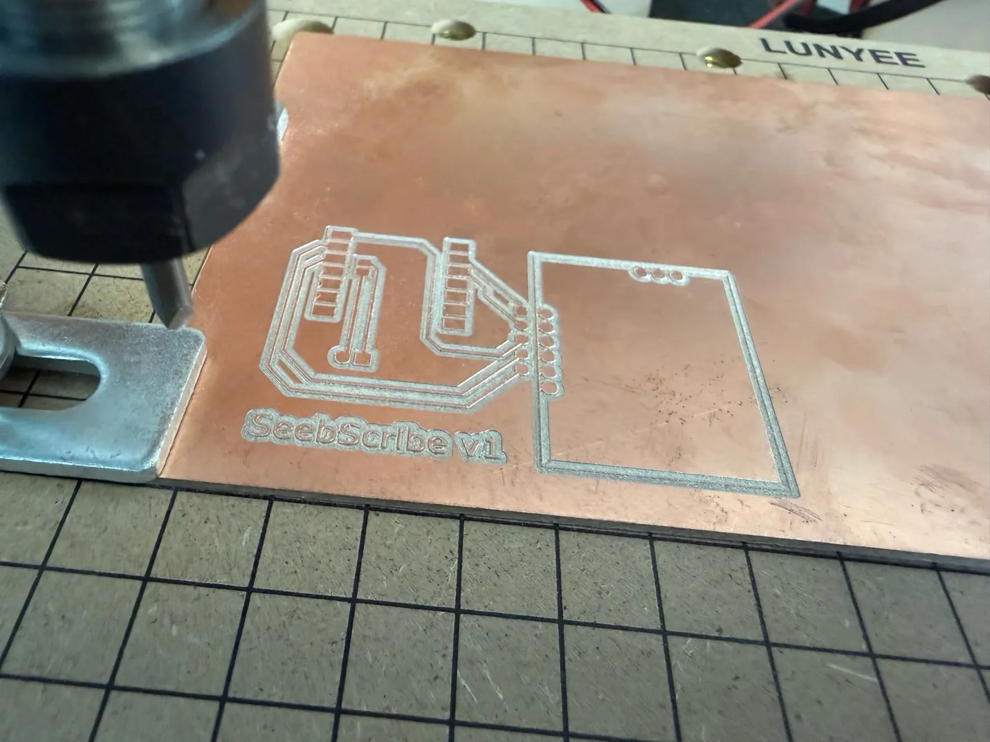
Milling the traces, pads, lettering, sensor area, and board outline from copper-clad stock.
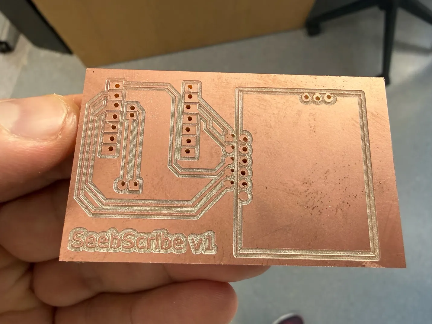
The finished milled board after drilling. This physical test confirmed the footprint scale and showed where more clearance was needed during assembly.
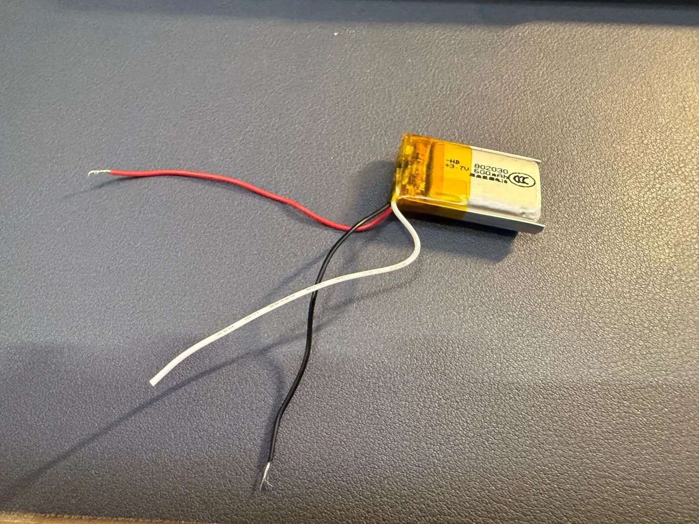
I selected a small 3.7 V, 600 mAh LiPo battery as the portable power source and prepared its leads for integration.
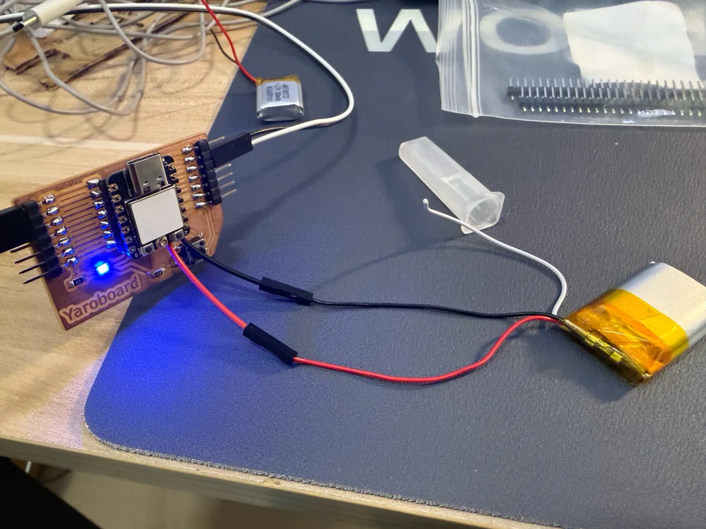
Before packaging, I verified battery power on an earlier XIAO carrier-board prototype. The illuminated LED confirmed that the controller could run independently from USB.
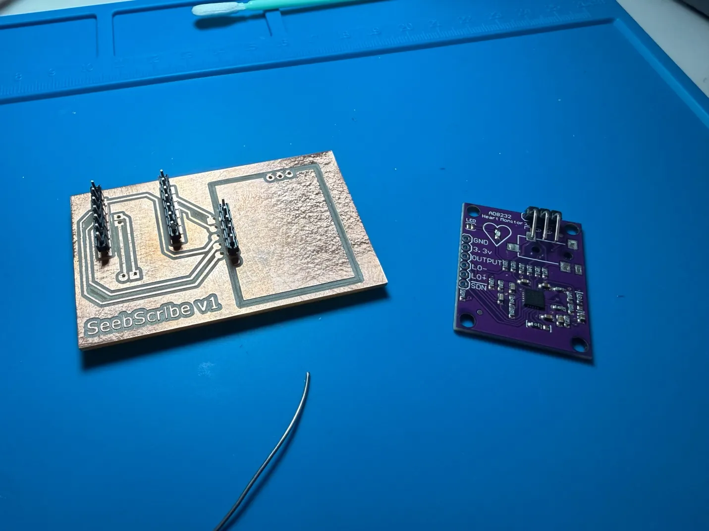
Headers were soldered to the custom board and checked against the AD8232 module. The removable connection made testing and replacement easier.
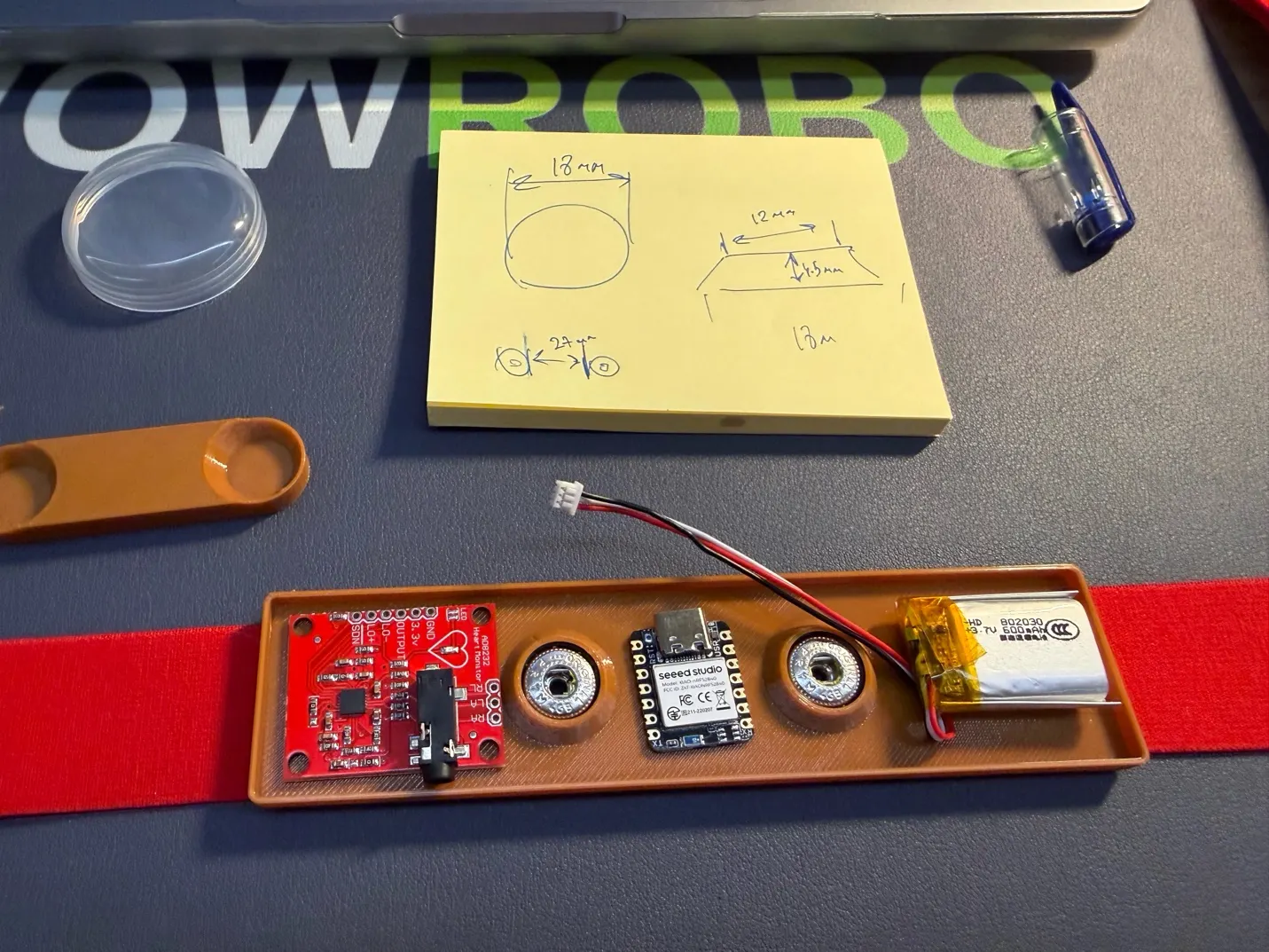
First body-worn integration test. The controller, AD8232 board, battery, and two snap electrodes were connected on the elastic chest strap to test the complete signal path.
Video of the integrated wearable prototype and the arrangement of the electronics on the strap.
Wearable layout, measurements, and CAD
After confirming the electrical system, I moved the parts onto the strap and treated their positions as a mechanical layout problem. The sensor board needs short connections to the snaps, the controller needs access to USB, and the battery needs a protected flat area. I used the real components to establish spacing before making the enclosure.
The powered system on the strap shows the functional relationship between the AD8232 input board, XIAO controller, battery, and chest contacts.
I measured the snap fasteners and sketched their main diameters and height. These dimensions were used to model recessed snap seats in the enclosure.
Component comparison before packaging: carrier PCB, AD8232 options, XIAO controller, battery, and snap contacts. This exposed the true footprint of the complete system.
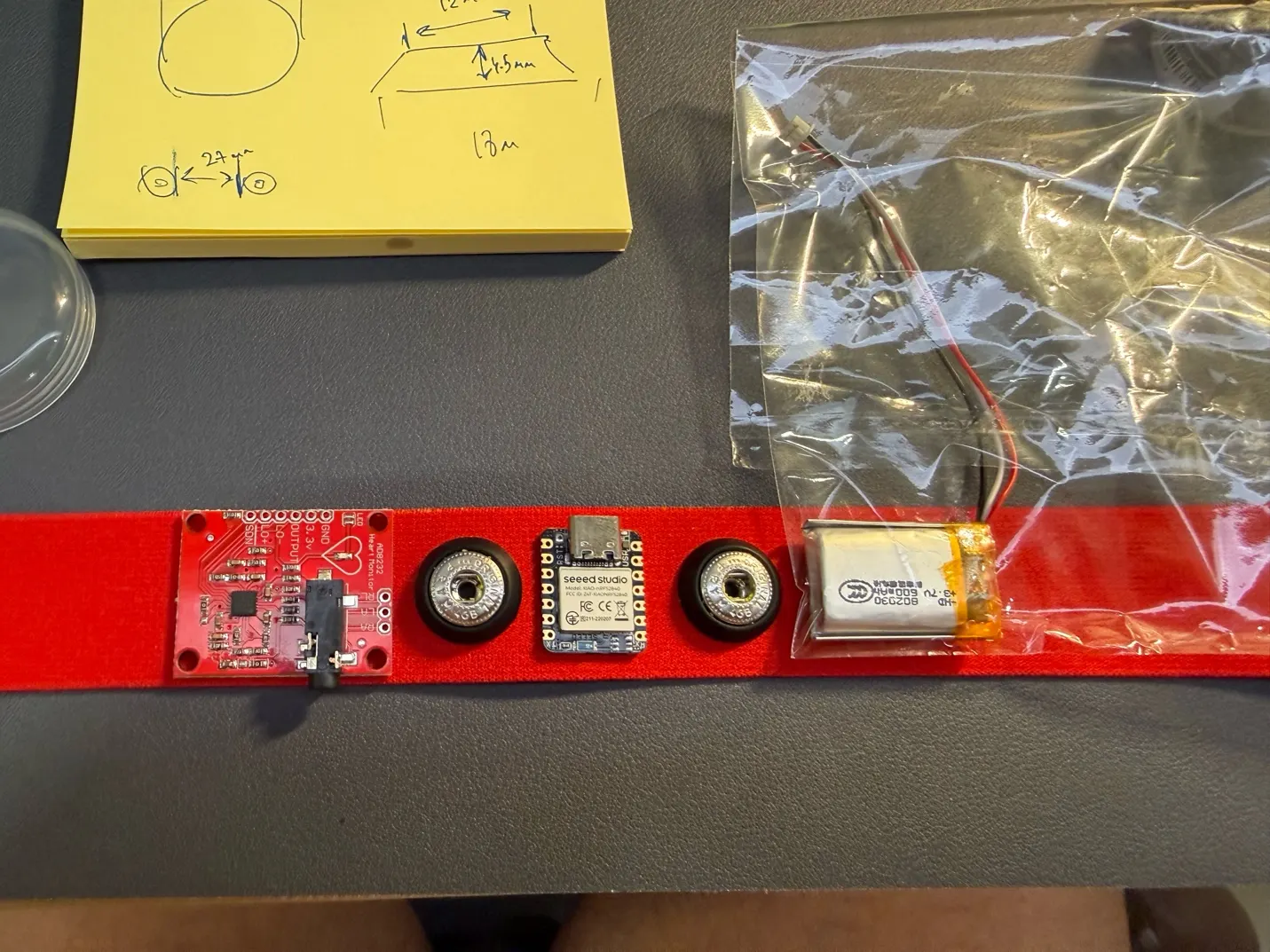
Final linear placement plan on the elastic strap: sensor board, snap electrode, controller, second snap electrode, and battery.
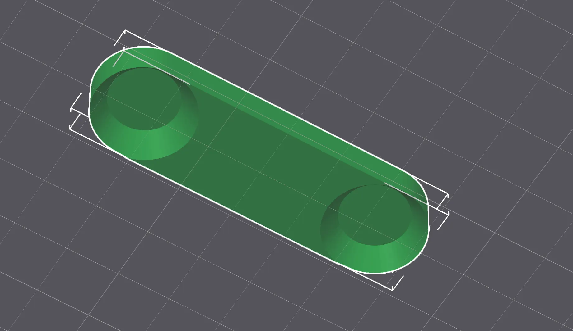
Early enclosure concept with rounded ends and two circular snap recesses. The soft outline avoids sharp corners against the body.
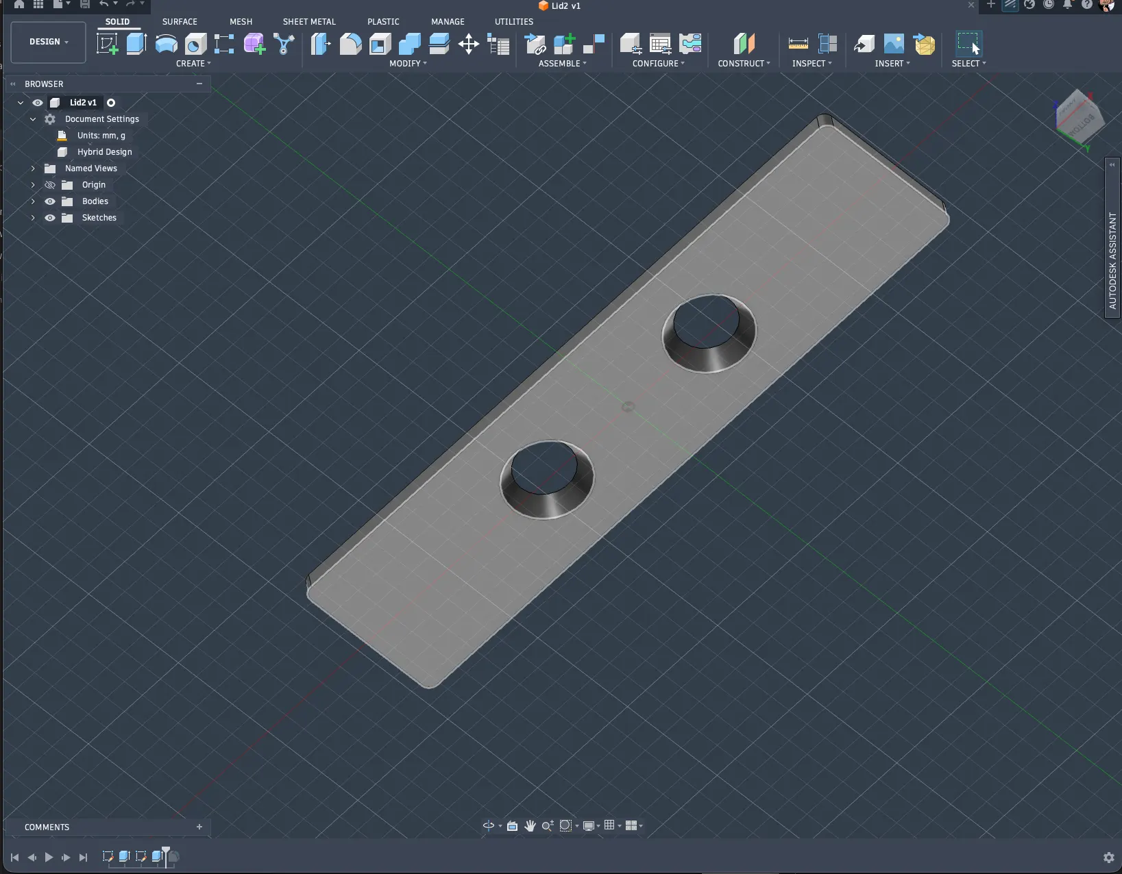
Outside view of the Fusion 360 model. The two raised circular features locate and support the electrode snaps.
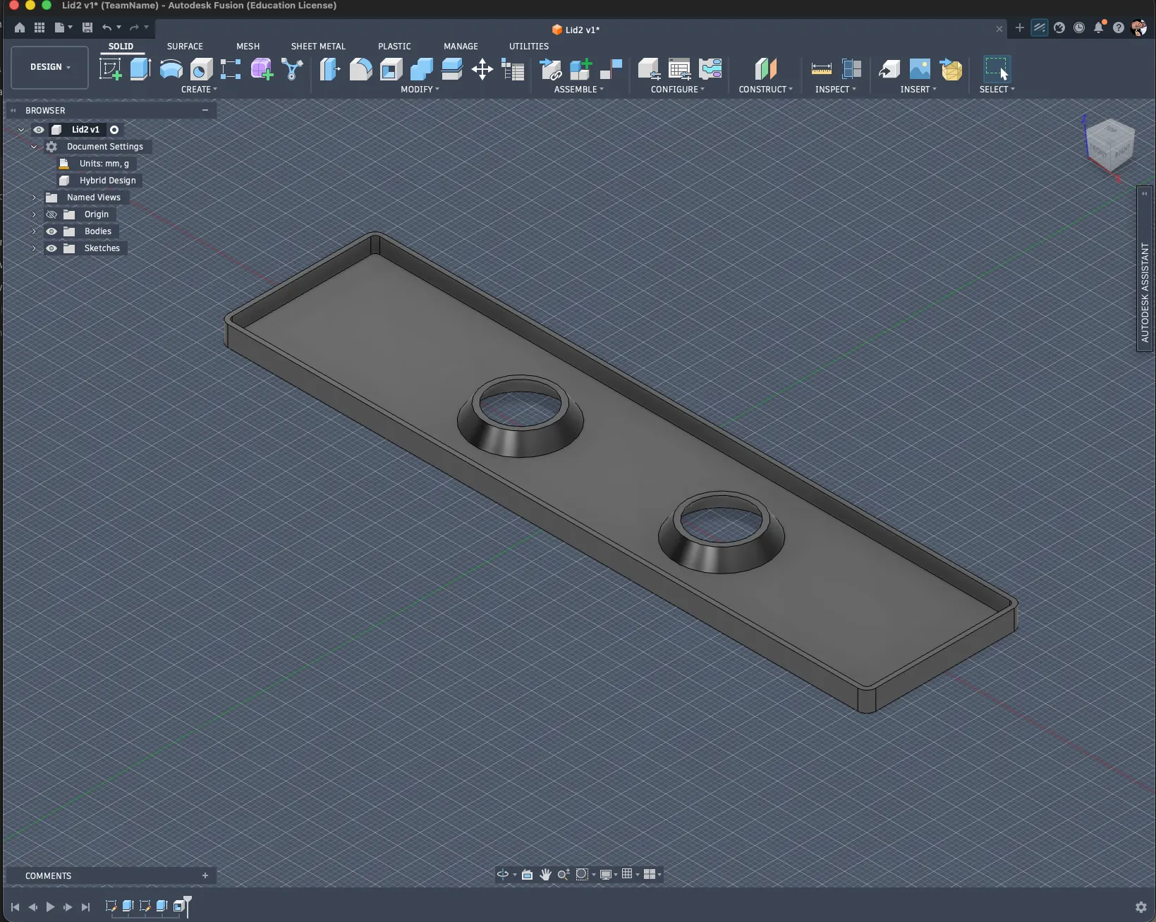
Inside view of the enclosure tray, with a perimeter wall to retain the electronics and tapered snap supports through the base.
First implemented packaging prototype. The printed tray holds the AD8232 board, two snaps, XIAO controller, and LiPo battery in one ordered assembly on the strap.
Final integration, reinforcement, and assembly
System integration meant more than connecting components electrically. I also needed to combine the carrier PCB, controller, heartbeat sensor, battery, electrode snaps, wiring, enclosure, and elastic strap into one rigid and usable object. The board and shell went through many iterations because every change to the PCB affected the enclosure, and every change to the enclosure affected component placement and access.
Implemented packaging methods
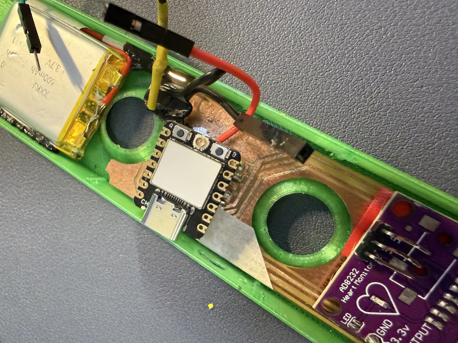
I designed the packaging around the dimensions and positions of the real electronic components. The opened final assembly below shows the component placement, internal cable routing, battery retention, snap connections, and local reinforcement methods.
| Packaging feature | Implemented method |
|---|---|
| Enclosure material | 3D-printed PETG |
| Wall thickness | 1 mm |
| Enclosure form | Long, rounded two-part shell designed around the actual components |
| Cover fastening | Fitted removable cover |
| Carrier PCB mounting | Fitted inside the enclosure and locally secured with low-temperature 3D-pen filament |
| AD8232 mounting | Positioned at one end near the electrode wiring |
| Controller mounting | XIAO ESP32-C3 mounted centrally on the custom carrier PCB |
| Battery mounting | LiPo battery retained in a dedicated end compartment |
| Cable routing | Wires routed along the internal edges between the sensor, carrier PCB, battery, and snaps |
| Strain relief | Low-temperature 3D-pen filament applied around wires, connectors, and board edges |
| Strap attachment | Metal snap fasteners provide electrical contact and removable mechanical attachment |
| Maintenance access | Removable cover with access to the XIAO USB connector |
| Rigidity | PETG shell, fitted components, snap supports, and local 3D-pen reinforcement |
| Iteration method | Multiple PCB and enclosure versions were fabricated until all parts fitted and operated together |
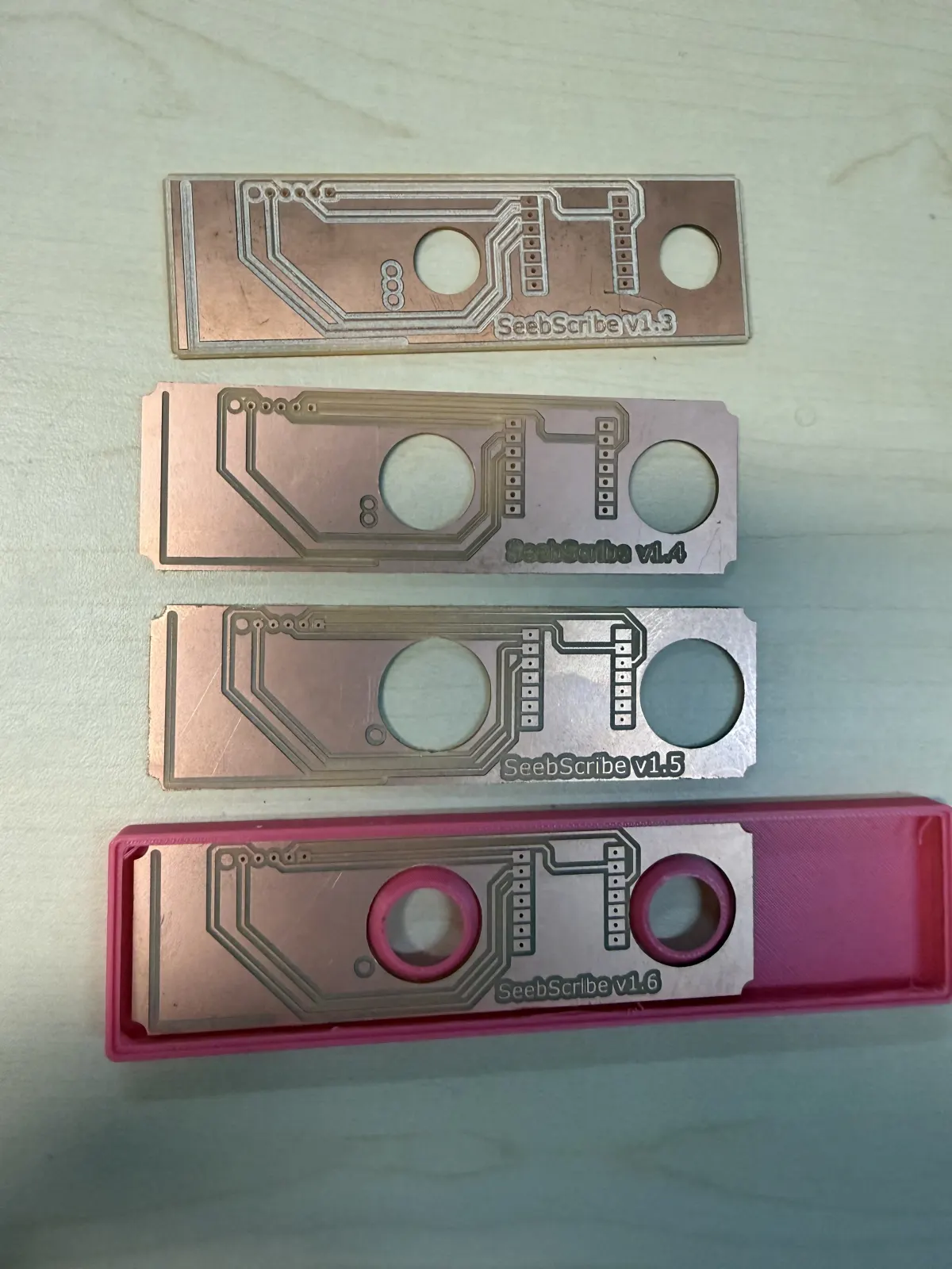
Several PCB and shell iterations placed together. Changes to trace routing, hole sizes, board dimensions, and enclosure fit gradually produced a version that could hold all components as one assembly.
Integrating the electrode snaps with the internal electronics. The snap wiring, XIAO controller, AD8232 board, battery, and enclosure all had to align while remaining electrically connected.
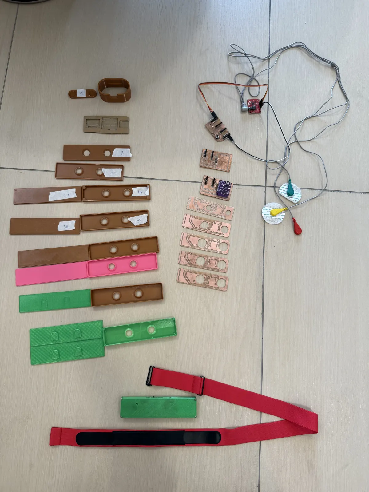
The full collection of integration iterations: carrier boards, enclosure bases and covers, snap layouts, sensor tests, and the elastic chest strap. This shows how many physical versions were needed before the system worked together.
For the final assembly, I used a 3D pen with low-temperature filament to secure loose wires, reinforce the snap connections, and hold the boards inside the shell. Designing and printing a new plastic part for every small support would have required many additional iterations. The 3D pen let me add material only where it was needed, quickly test the result, and make the integrated assembly more rigid and solid. After these electrical and mechanical iterations, the complete wearable system is working.
Low-temperature 3D-pen filament was added around wires, connectors, and board edges to prevent movement and make the internal assembly more rigid without redesigning the entire shell.
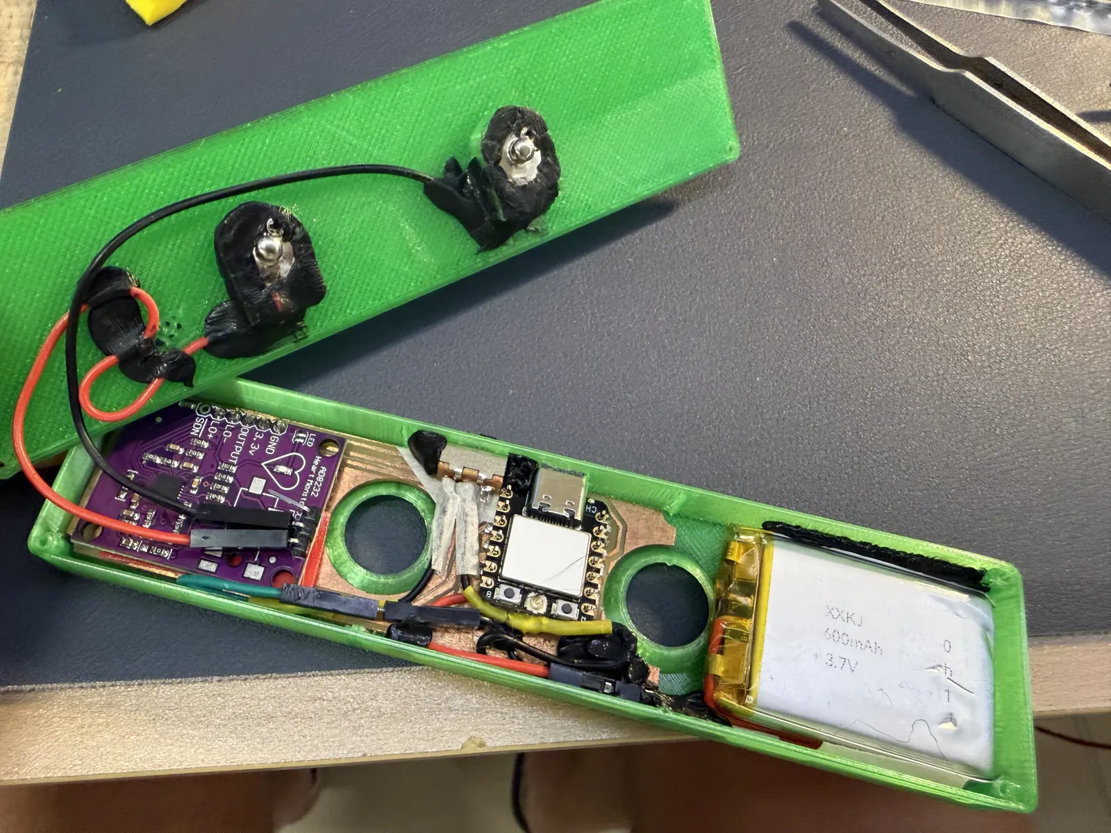
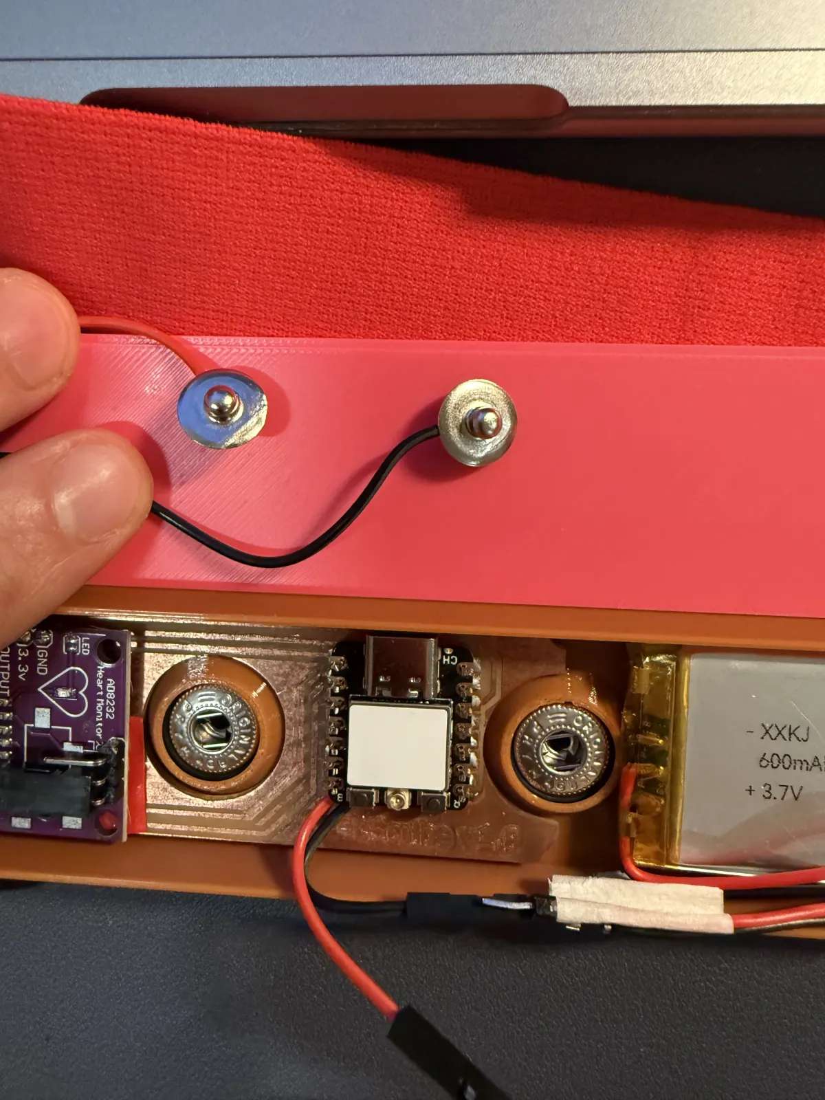
The opened final assembly shows the AD8232 board, custom PCB, XIAO controller, battery, wiring, and reinforced snap connections fitted into the enclosure.
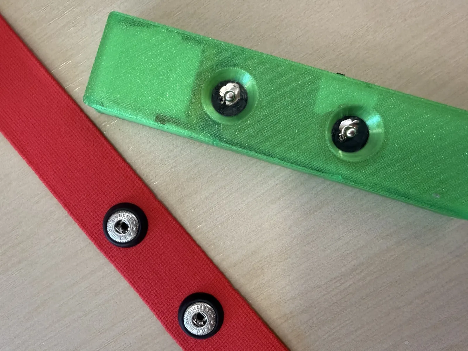
The two enclosure snaps align with the matching contacts on the elastic strap, creating both the body-contact interface and a removable mechanical attachment.
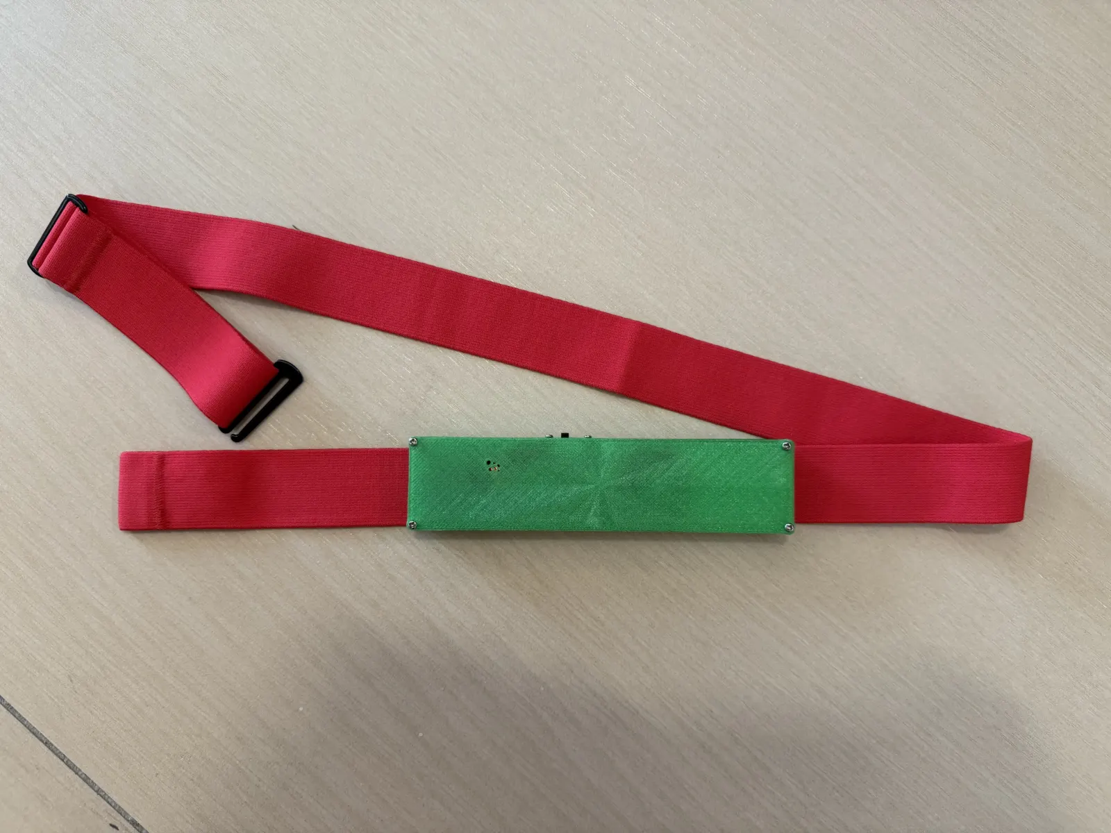
The completed working system: the electronics are enclosed in a rigid shell and attached to the adjustable chest strap as one integrated wearable prototype.
Design files for download
The final fabrication and programming files used for the integrated Seebscribe prototype are available below. The same files are also referenced from the final project page.
- Download the Gerber files for the carrier circuit board
- Download the 3D-printable enclosure file (3MF)
- Download the carrier PCB 3D model (STEP)
- Download the Arduino program for the XIAO ESP32-C3
Reflection
This process showed me that system integration is not simply putting every finished module into a box. The PCB outline, connector orientation, electrode spacing, battery position, strap width, and enclosure geometry affect one another. Building the physical layout early revealed issues that were not obvious in the schematic, especially cable length, access to the USB connector, and the amount of space required by the AD8232 module.
The first tray demonstrated the component arrangement, but it was not rigid enough for a wearable device. Later shell, PCB, snap, and wiring iterations improved the fit, while the 3D-pen reinforcement provided practical strain relief and stopped the internal parts from moving. The final version has a fitted cover, connects securely to the elastic strap, and works as one complete Seebscribe prototype.