Week 2 Computer-Aided Design
Week 2 Assignment:
Learning outcomes
- Evaluate and select 2D and 3D software
- Demonstrate and describe processes used in modelling with 2D and 3D softwares
- Demonstrate image and video compression
Introduction
This week's assignment was to model a possible final project using both 2D and 3D computer-aided design tools, and to evaluate which software workflows are most suitable for the work ahead.
I used this week to explore the form and structure of an organic lamp shade — a 3D-printable lattice structure designed to produce interesting light distribution patterns through its geometry. The object is intended to be fabricated using an FDM printer and functions as both a structural and visual element of a lighting fixture.
To approach this, I worked across several tools: GIMP and Adobe Illustrator for 2D concept and visual work, and Rhino 8 and Fusion 360 for 3D form development.
Raster and Vector Graphics
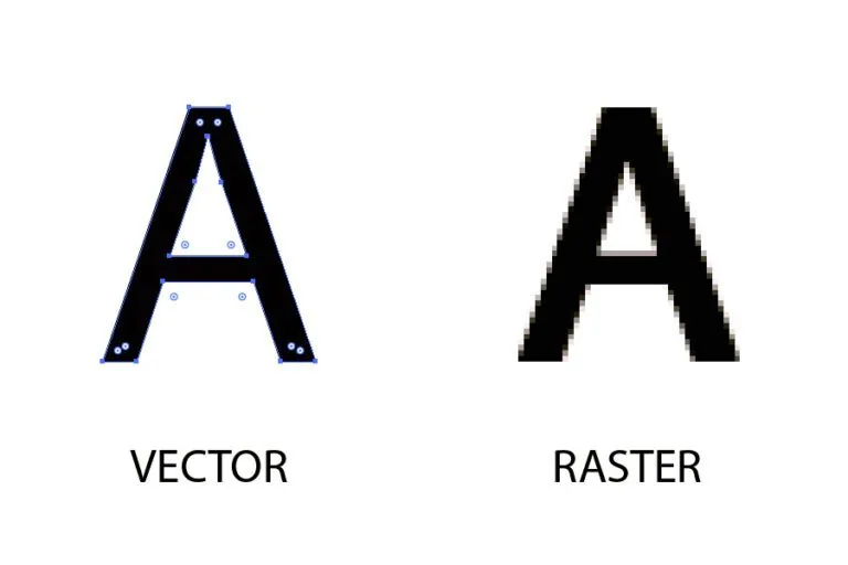
Before working with 2D software, it is important to understand the two fundamental types of digital images, because the choice between them determines which tool is appropriate for the task.
A raster image is made up of a fixed grid of pixels. Each pixel holds a color value, and together they form the image. Because the resolution is fixed, scaling a raster image up beyond its original size causes pixelation - the individual pixels become visible and the image loses sharpness. Raster is best suited to photographs, textures, and light effects. Common formats are PNG and JPG. GIMP is a raster editor.
A vector image is built from mathematical paths - lines and curves defined by anchor points rather than pixels. This means a vector shape can be scaled to any size without any loss of quality. Vector is best suited to logos, technical drawings, and any work that needs to be sent to a cutting or engraving machine. Common formats are SVG and AI. Adobe Illustrator is a vector editor.

| Criteria | Raster | Vector |
|---|---|---|
| Made of | Pixels | Mathematical paths |
| Scalability | Loses quality when enlarged | Scales without quality loss |
| Best for | Photos, textures, light effects | Logos, technical drawings |
| Tools used this week | GIMP | Adobe Illustrator |
2D Design
Raster Graphics (GIMP)
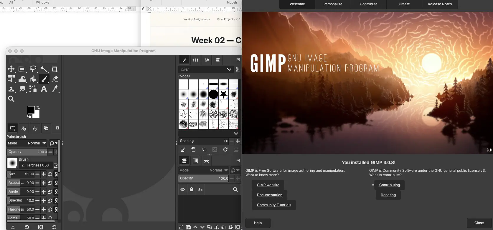
GIMP (GNU Image Manipulation Program) is a free, open-source raster image editor. It is widely used as an accessible alternative to Photoshop for photo editing, digital painting, and image compositing. You can download it at gimp.org.
The GIMP interface has four main areas. The Toolbox runs along the top-left and holds all tools for drawing, selecting, transforming, and color-picking - clicking any tool activates it. Directly below the toolbox is the Tool Options panel, which updates instantly to show the settings for whatever tool is currently active - in this screenshot the Paintbrush is selected, showing controls for opacity, brush size, hardness, and spacing. The large central area is the canvas, where all drawing and editing happens - the zoom level is shown at the bottom of the screen and can be adjusted freely without affecting the actual image resolution. On the right side is the Brushes panel, which lets you select from a library of brush shapes and textures. Below it is the Layers panel, which shows all the layers in the current document - each layer can be edited independently, making it easy to work on different parts of an image without affecting the rest.
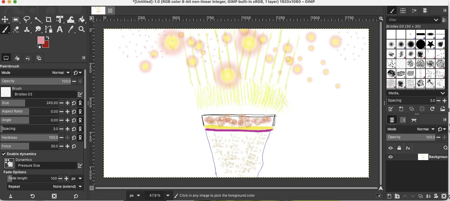
For this week, GIMP was used as a first hands-on exploration of raster editing to get familiar with basic tools and workflow. I experimented with simple shapes and light/reflection effects to test brush-based editing and soft-effect control.
GIMP is straightforward for basic tasks. For this project it is not the primary tool, but it is useful to understand raster editing as a foundation before moving to more specialized software.
Vector Graphics (Adobe Illustrator)
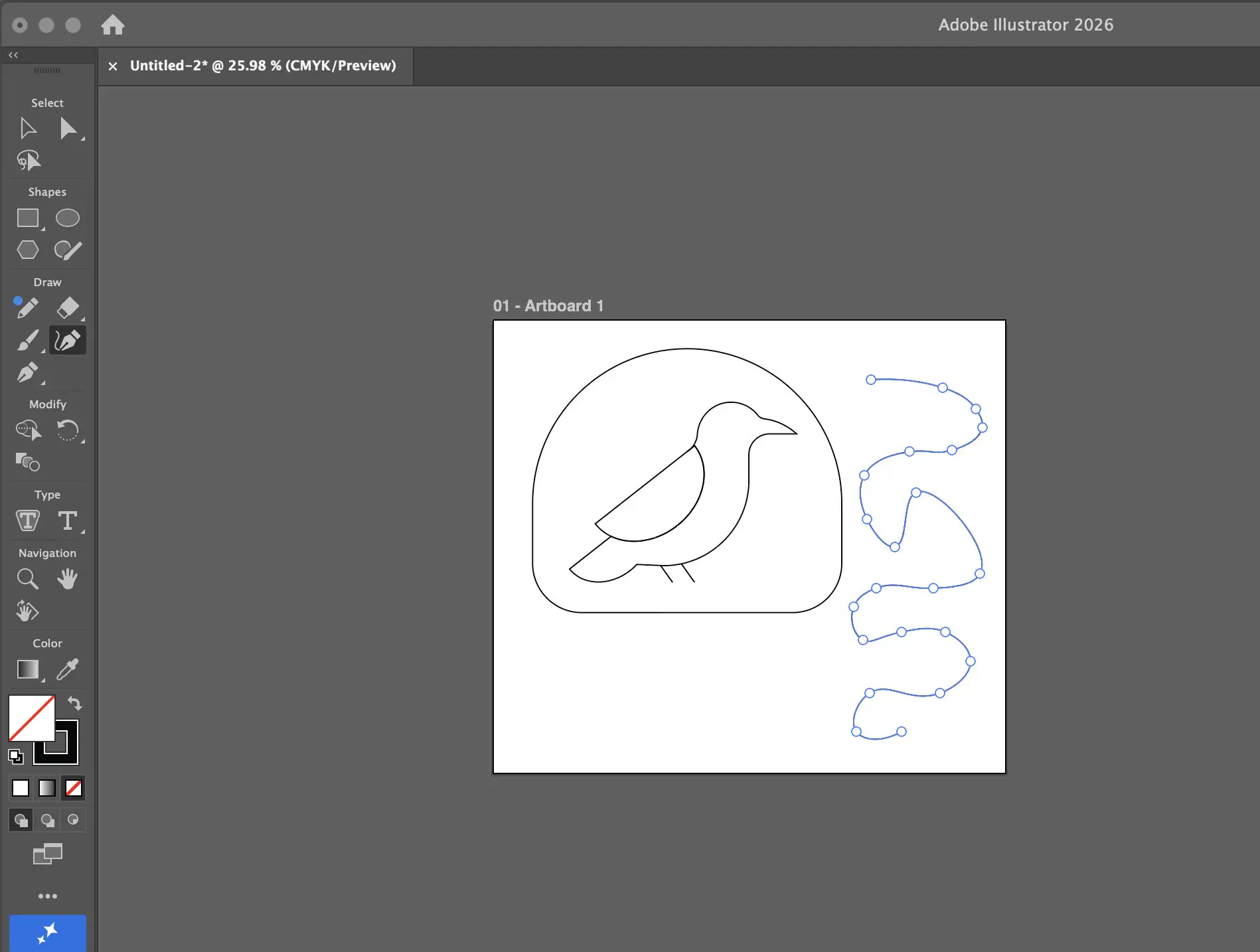
Illustrator was used to develop a 2D vector composition, practicing the core tools that are relevant to shape construction and vector workflows. Vector geometry is resolution-independent and precisely controllable, making it a standard tool for technical drawing, logo work, and concept illustration. The project built this week - a nature-themed logo - was used as an exercise to learn the key operations:
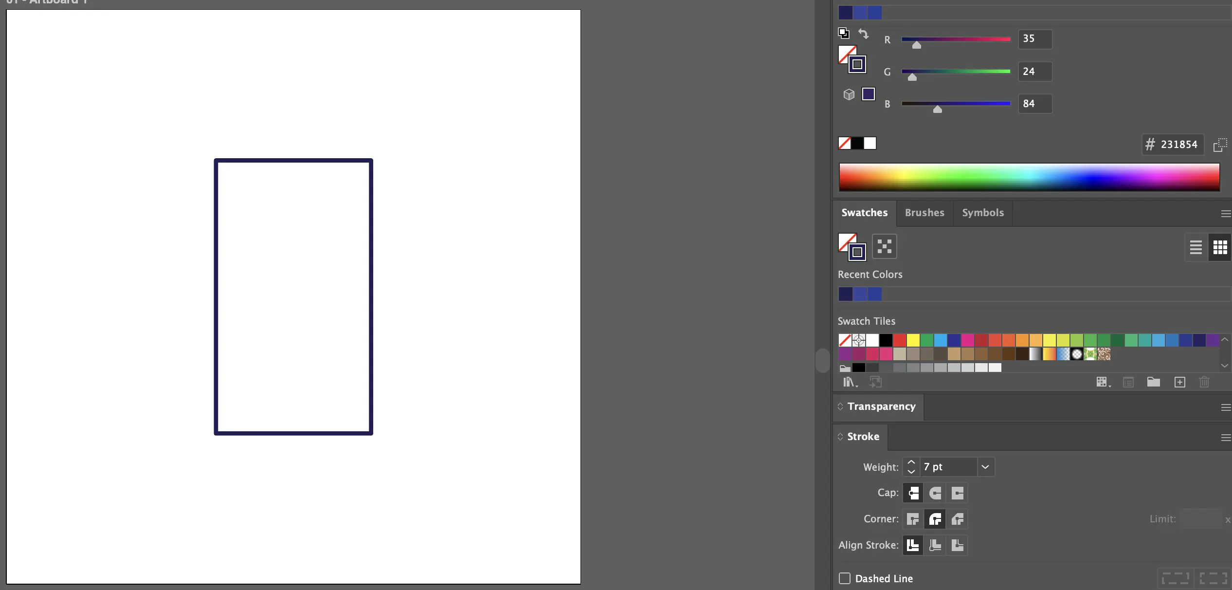
The composition was built on a 1000x1000 pixel artboard. A rectangle was placed at the center using the Align panel (Window > Align), with horizontal and vertical alignment set to the artboard. The fill was removed and the stroke was set to dark blue at 7 pt thickness. Working with stroke only at this stage keeps the form readable as a line drawing without committing to a color treatment.
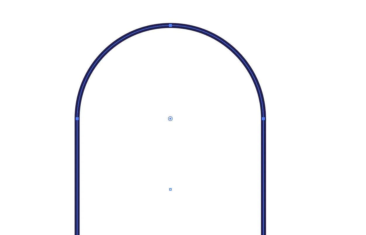
To round the upper corners, the Direct Selection tool (A) was used to select only the top two anchor points independently. Dragging these inward activates the corner radius handles, allowing the top of the rectangle to be shaped as an arch without affecting the lower corners. This is a non-destructive approach: the original rectangular structure remains editable underneath.
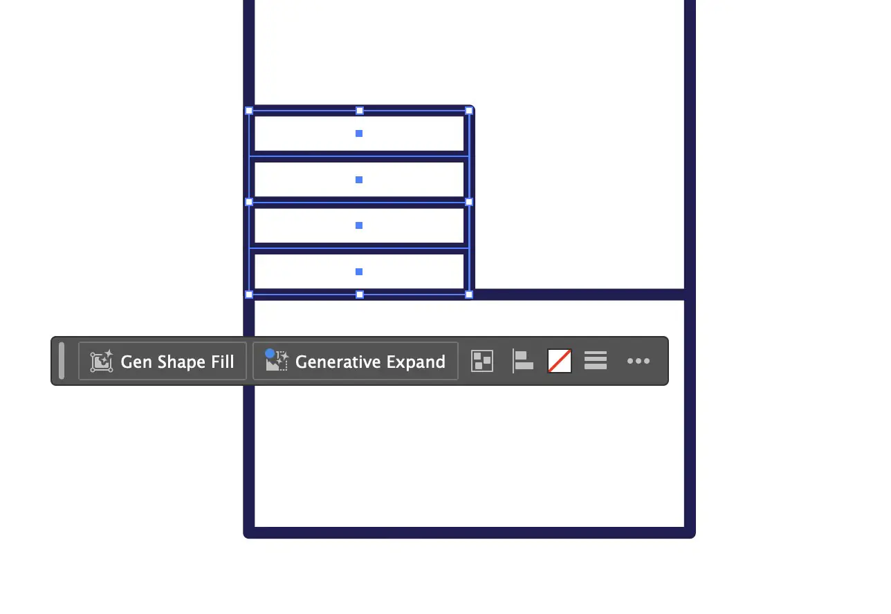
Tree shapes were constructed by drawing a vertical line for the trunk and stacking four circles on top, each created by holding Shift to constrain proportions. All four circles were then combined using the Pathfinder panel (Window > Pathfinder > Unite). The Unite operation merges overlapping and adjacent shapes into a single closed path, removing internal boundaries.
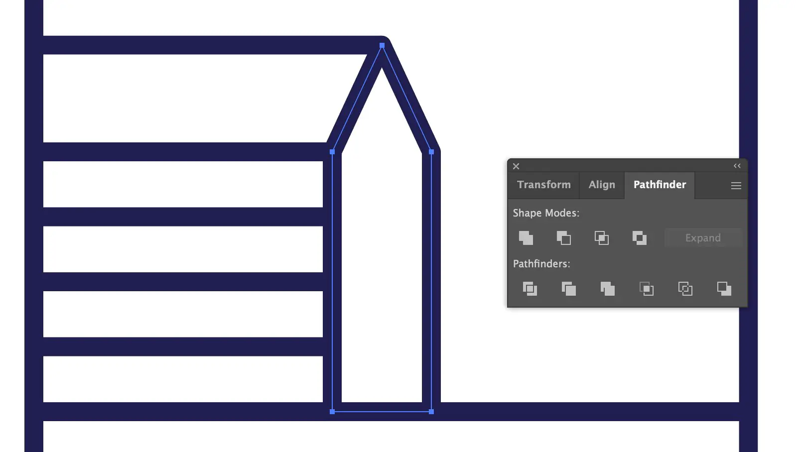
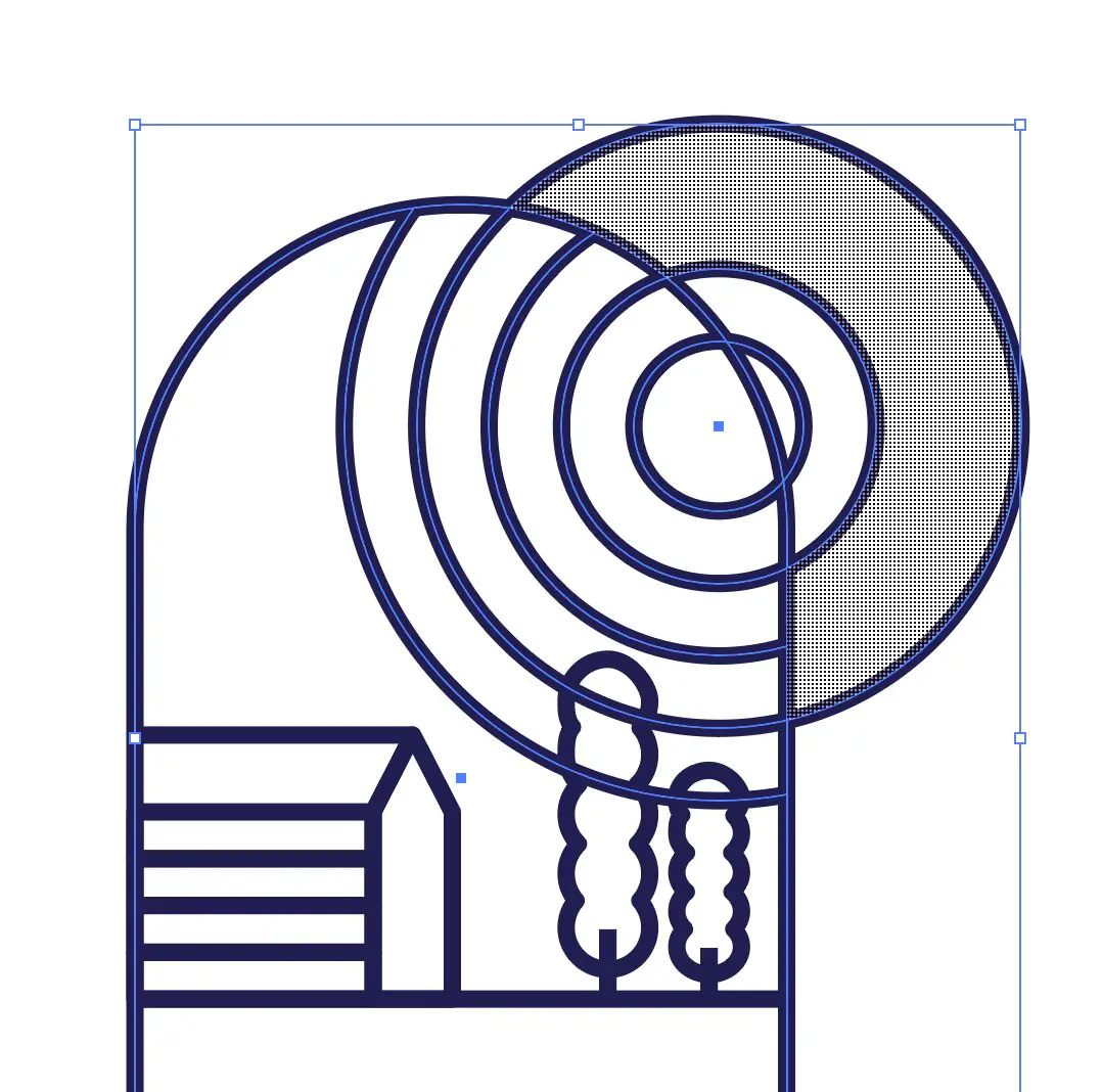
The sun rings were created using Object > Path > Offset Path with 30 px offset. Repeating this step produced concentric rings spaced evenly from the original circle. Where rings overlapped other elements, Shape Builder was used to remove unwanted segments. Holding Alt/Option switches the cursor to subtraction mode.
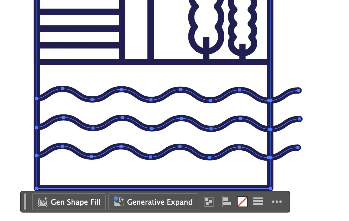
The water was created by drawing three horizontal lines, then applying Effect > Distort & Transform > Zigzag with Smooth selected. After that, Object > Expand Appearance was used to convert the live effect into editable paths. This step is required before further geometry editing.
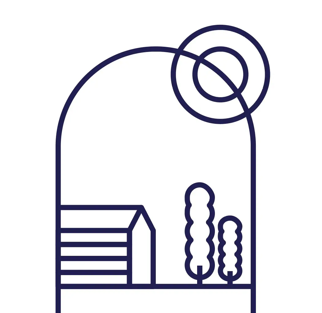
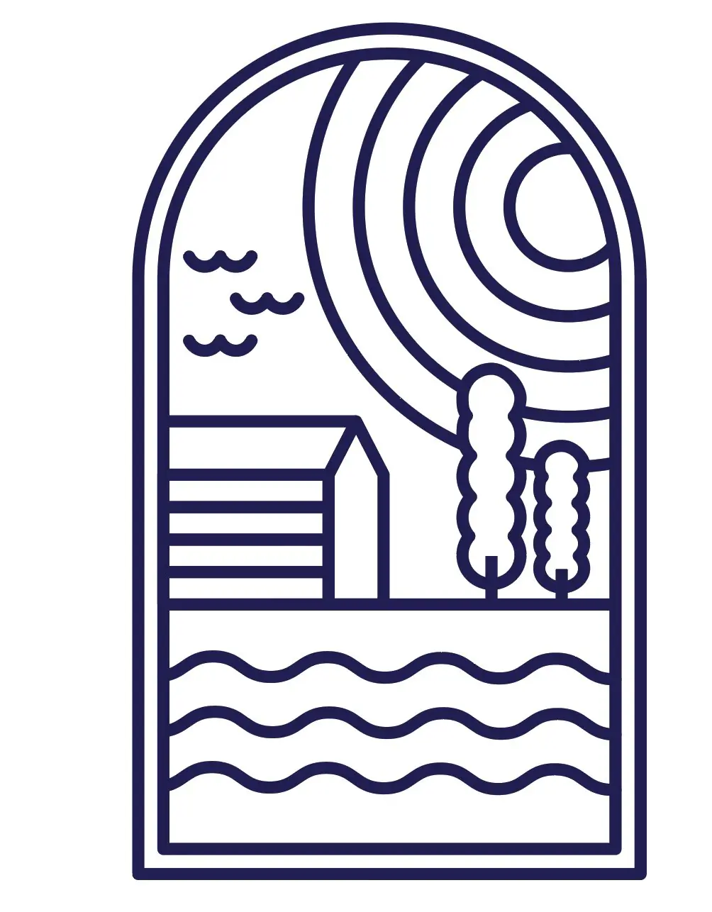
Completed composition including house, trees, sun rings, water lines, and bird.

Illustrator is effective for clean, scalable vector construction and Boolean shape operations. It is not suited to volumetric form development, so it served as a concept and technique exercise this week. The core operations - Unite, Offset Path, and Shape Builder - are directly transferable to future 2D drawing and fabrication template workflows.
3D Design
Rhino 8
Rhino is a NURBS-based 3D modeling software widely used in industrial design, architecture, and product development. It is particularly strong for free-form surface modeling - building complex curved surfaces from profile curves and rail curves. You can download it at rhino3d.com.
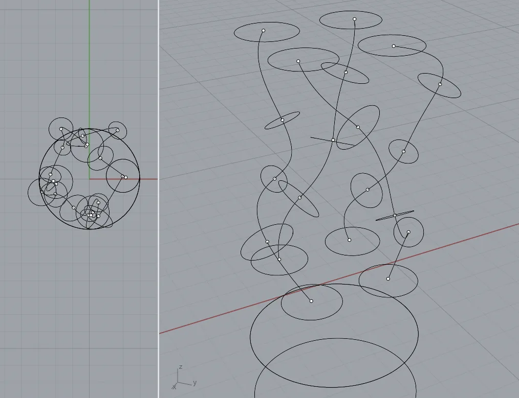
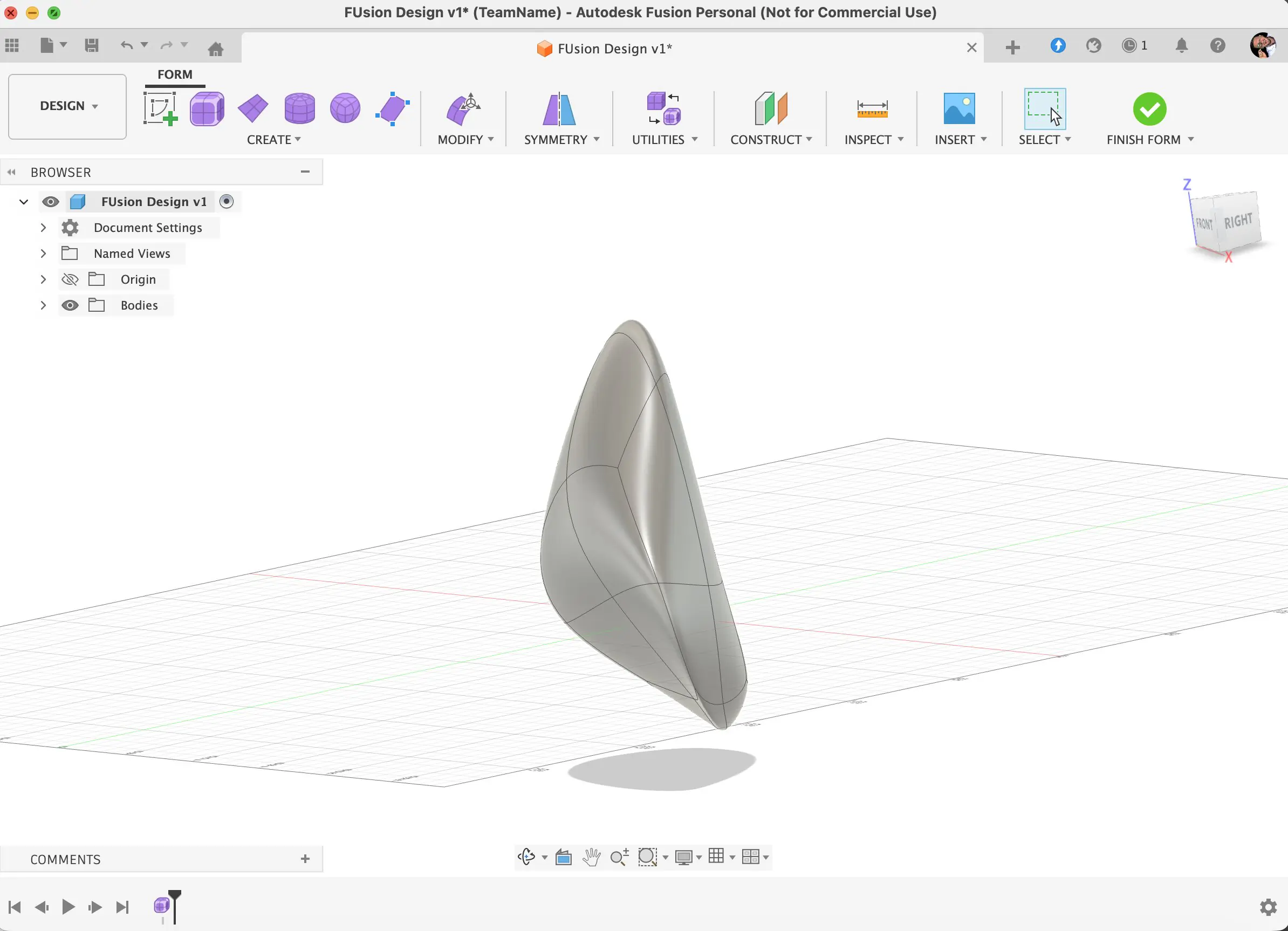
Rhino was used this week to explore how organic curves can be constructed and controlled for a lamp enclosure shape, testing whether its surface tools are suitable for the kind of form the final project requires.
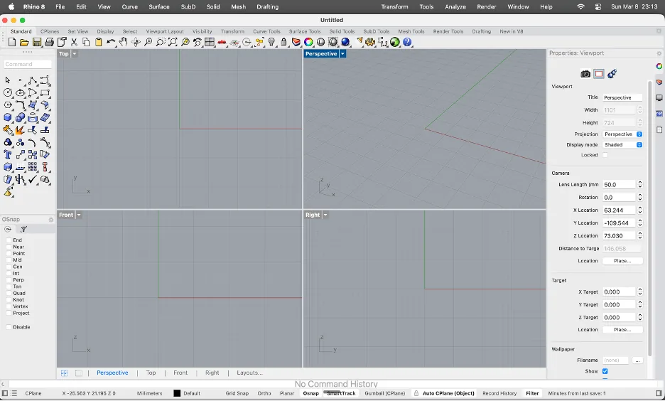
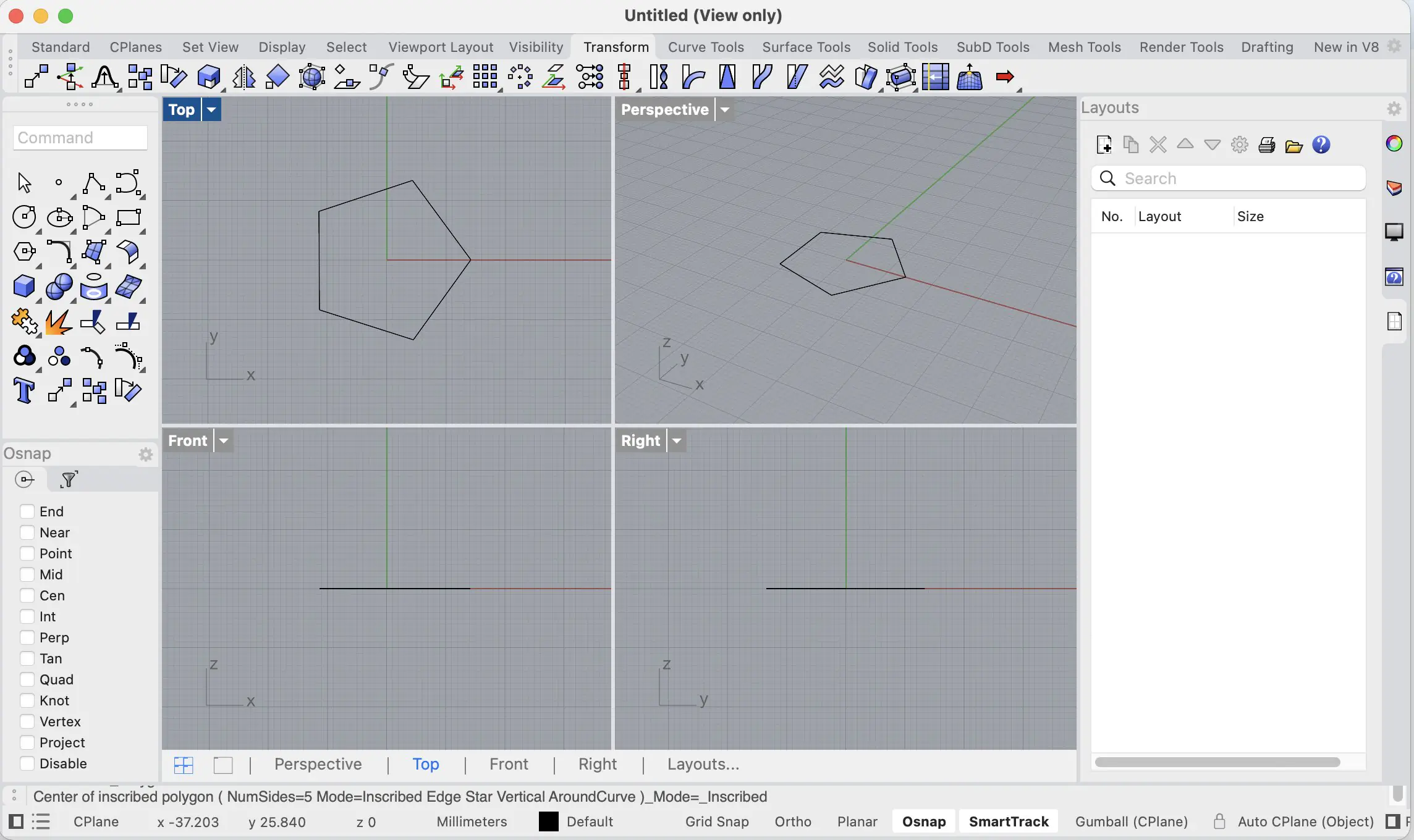
Rhino 8 uses a default four-viewport layout: Top, Front, Right, and Perspective, so the model can be checked from several angles at once. Most 3D navigation happens in the Perspective viewport, while flat views are used for precise 2D curve placement and alignment. Clicking a viewport label activates it.
Navigation is handled with mouse controls: right-click + drag rotates, middle-click pans, and scroll zooms. Along the top is a context-sensitive toolbar row including Standard, CPlanes, Surface Tools, Solid Tools, and Mesh Tools. On the left is the main toolbox with drawing, selection, and transform icons.
The most important input area is the Command line (top-left): in Rhino, most operations are executed by typing commands and pressing Enter, which is faster than searching menus.
Along the bottom, OSnap (Object Snap) enables precise snapping to points, midpoints, centers, and intersections. The status bar shows and controls key toggles such as CPlane, coordinates, Grid Snap, Ortho, Gumball, and Record History. On the right side, the Properties panel displays settings for the selected viewport or object.
For inspiration, I used this short video: https://www.youtube.com/shorts/8WuoeBPMg7Y
Phase 1: Base Construction
- Draw a circle and make a copy of it. (Type Circle and press Enter, then use Copy or Ctrl+C/Ctrl+V)
- Use the Offset tool to create another circle based on the first one. (Type Offset, select the curve, and click inside or outside to set the distance)
- Apply the Polar Array to duplicate the geometry into a circular pattern. (Type ArrayPolar, click the center point, and type the number of copies you want, like 6 or 8)
- Delete any extra circles you don't need. (Click the unwanted lines and hit Delete)
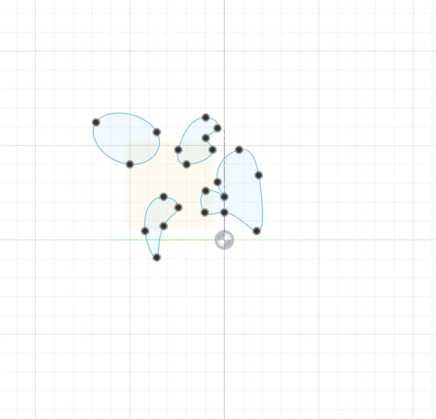
Phase 2: Center Definition and Curve Adjustment
- Use the Polyline tool to draw the center of the shape. (Type Polyline to click and draw straight lines)
- Apply the Polar Array again to create additional copies of the center structure. (Right-click to repeat the last command, ArrayPolar)
- Rebuild the curve and adjust the control points to ensure the curves are accurate. (Type Rebuild to change point count, then press F10 to see dots and drag them to fix the shape)

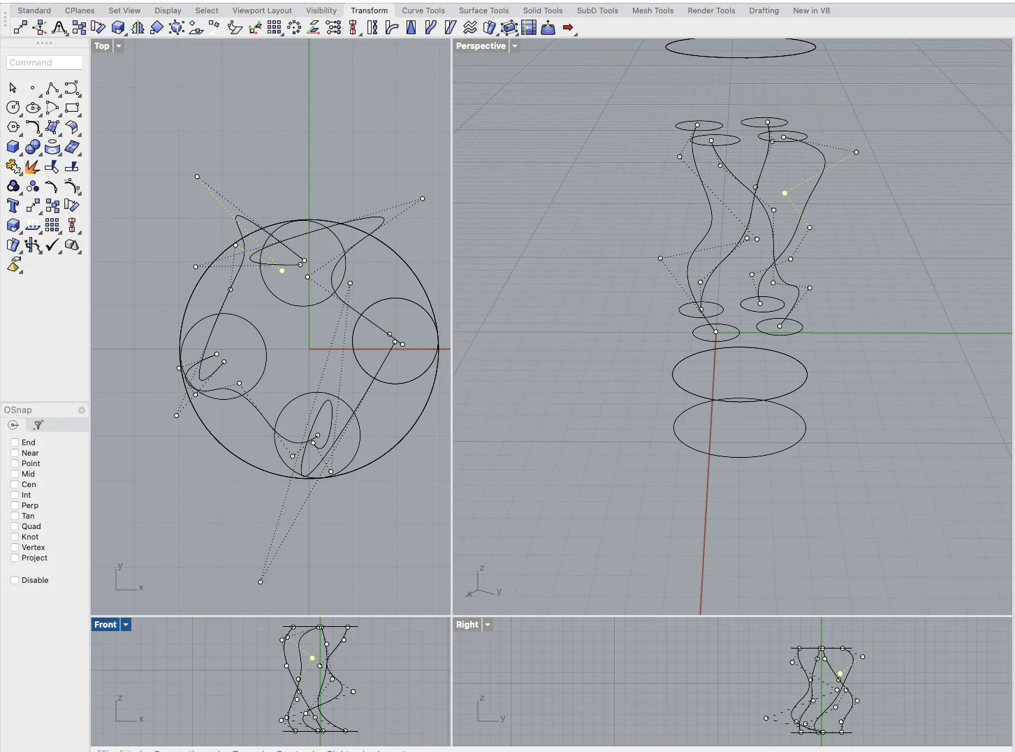
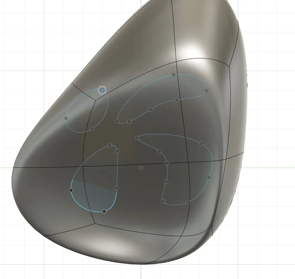
Phase 3: 3D Form Generation
- Divide the curves into four segments. (Type Divide, click the curve, and enter '4')
- Draw circles of varying sizes at each division point. (Make sure Osnap is on so you can snap the circles right onto the dots)
- Use the Loft tool to connect these circles. (Type Loft, click the circles in order, and hit Enter to make the skin)
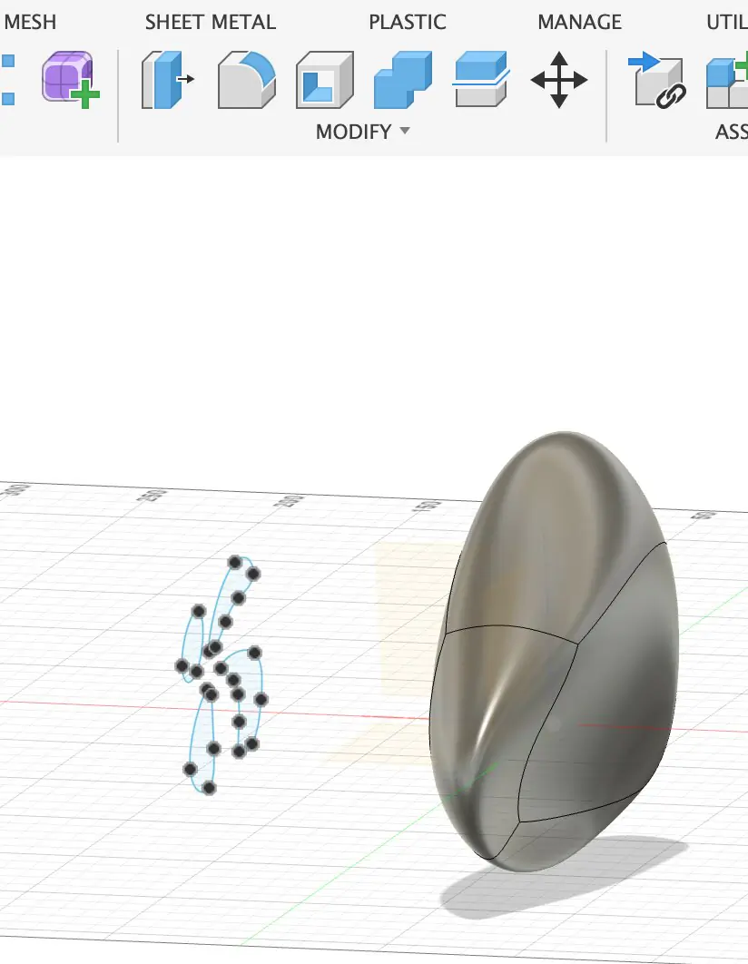
- Extrude both the top and bottom of the shape. (Type ExtrudeCrv or just use the Gumball arrows to pull the shape up and down)
Phase 4: Finalization
- Employ the Cap tool to close it off and make it solid. (Type Cap to fill in the flat holes)
- Follow with a Boolean Union to merge the elements. (Type BooleanUnion and select everything to glue it into one piece)
- Finally, utilize the Quad Mesh feature to unify your object. (Type QuadRemesh to clean up the geometry lines)
OnShape
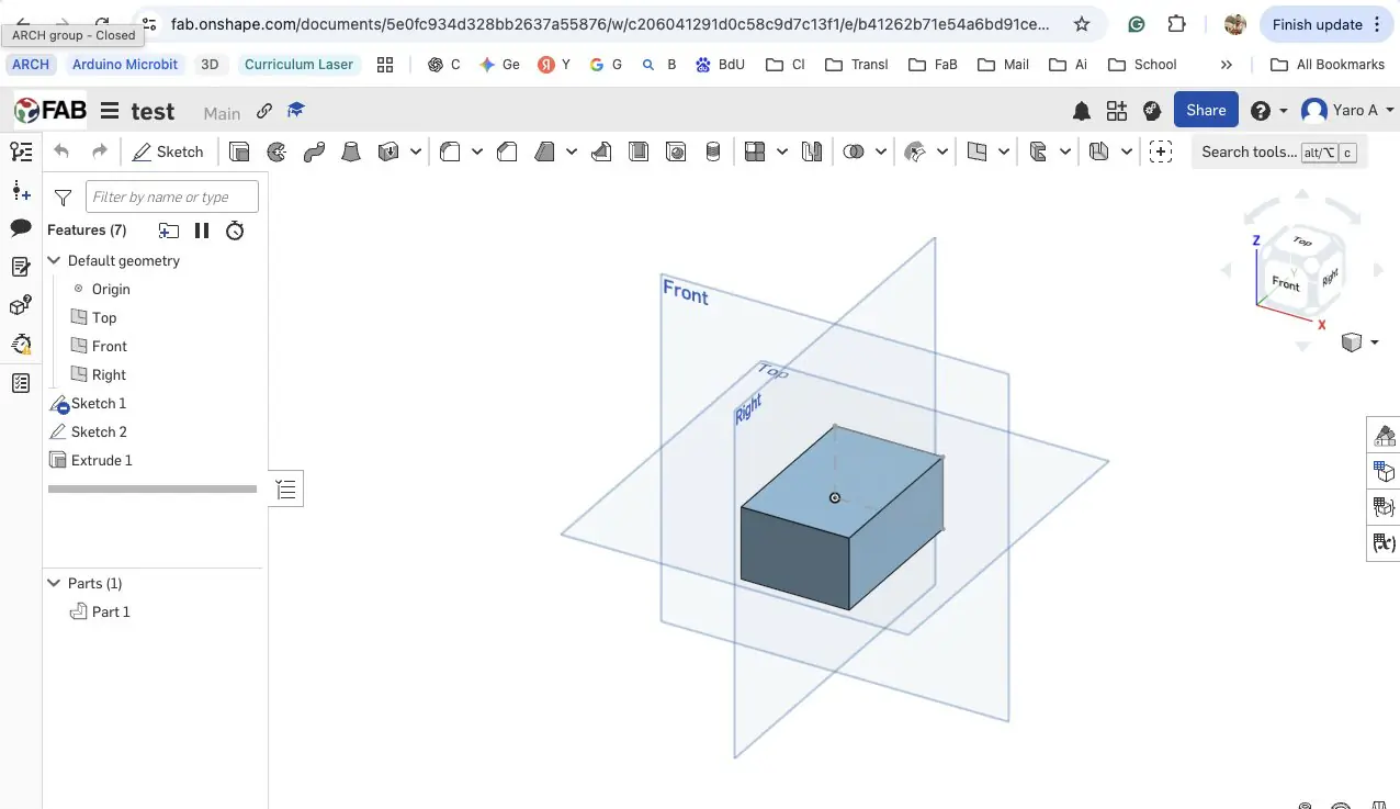
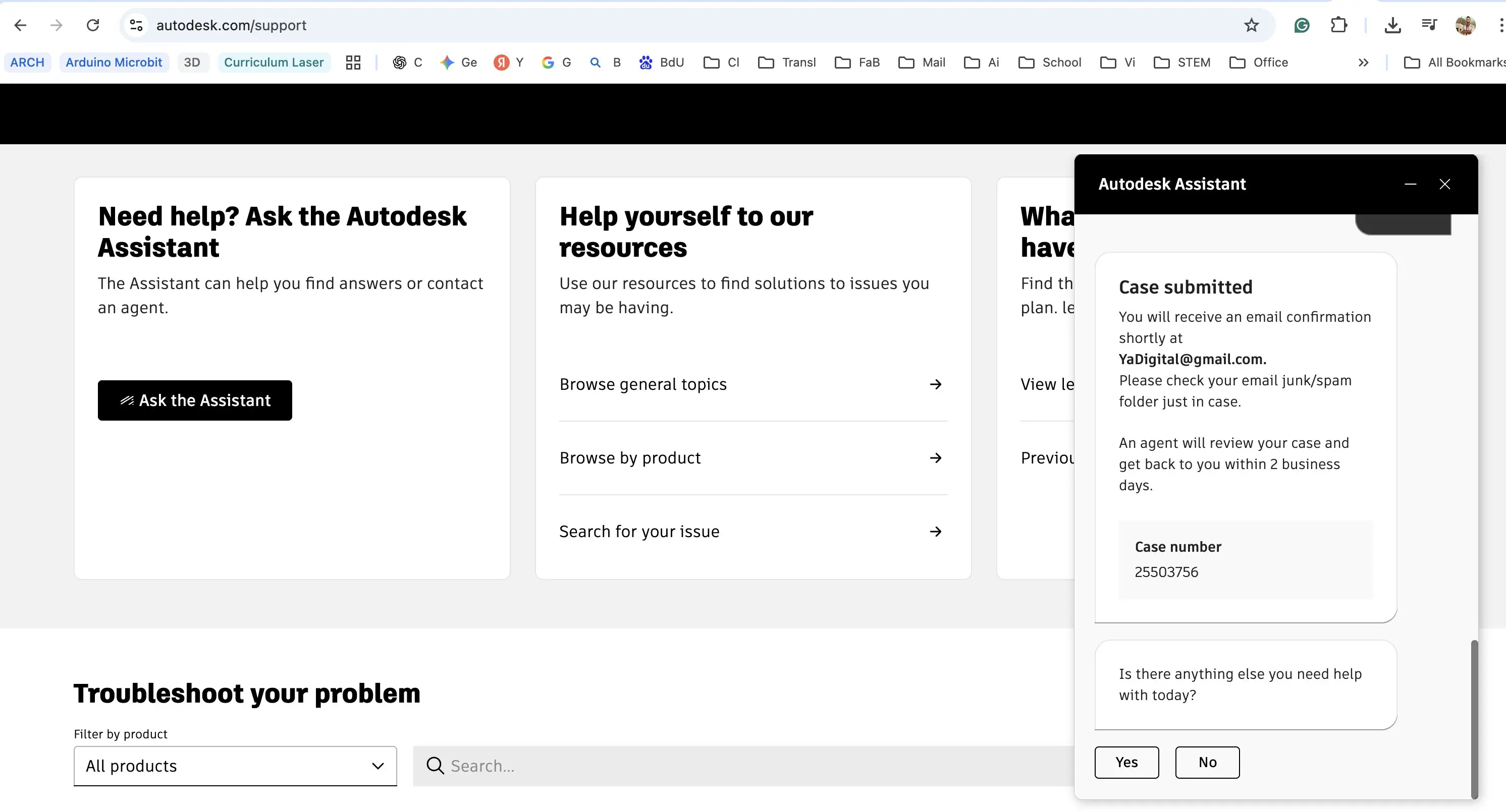
OnShape is a browser-based parametric CAD tool that runs entirely in the web browser without requiring installation. It can be accessed and linked directly through the Fab Academy student account - the connection is made at fab.onshape.com, where logging in with Fab Academy credentials links the workspace to the programme account.
OnShape uses a sketch-and-extrude parametric workflow similar to Fusion 360, where all modeling steps are recorded in a feature history that can be edited at any point. For this project, a basic shape was modeled to test the interface and confirm the account connection. Because the workflow and logic are close to Fusion 360, further 3D development this week was focused there rather than duplicating effort across both tools. OnShape remains a useful option for future weeks, particularly when working away from a local machine.
Fusion360
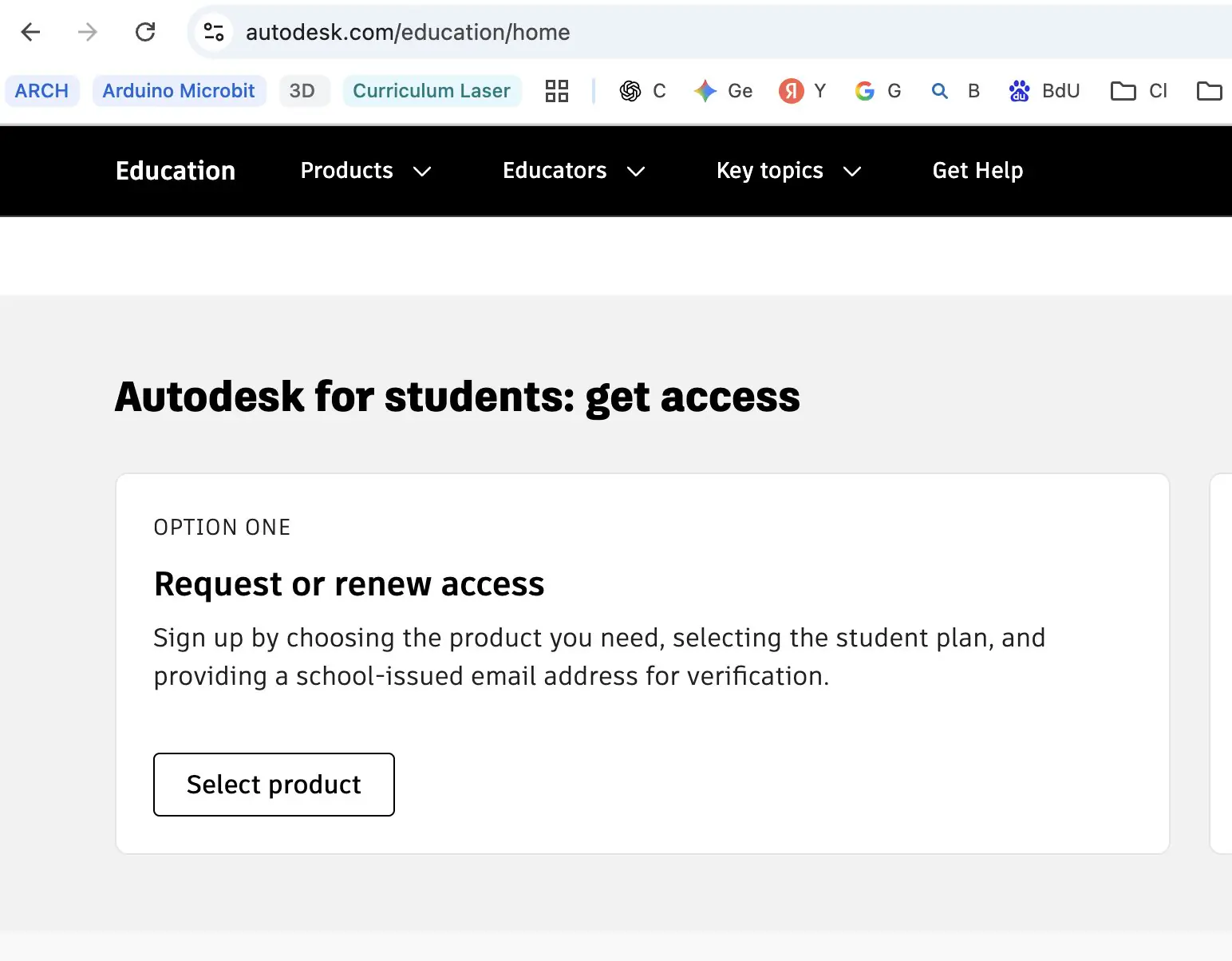
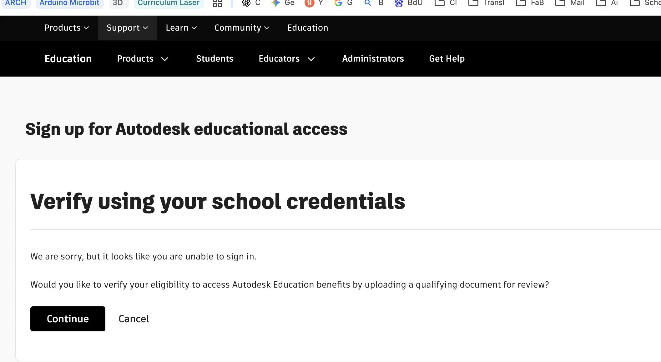
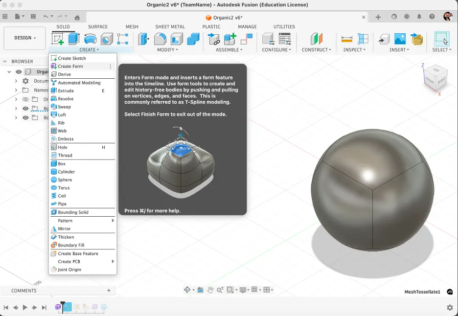
Fusion 360 is a professional parametric CAD tool developed by Autodesk that combines solid modeling, surface modeling, mesh tools, and CAM in a single environment. It is available for free to students and educators and can be downloaded at autodesk.com/fusion. A useful YouTube course for getting started is Product Design Online, which covers both fundamentals and more advanced workflows clearly.
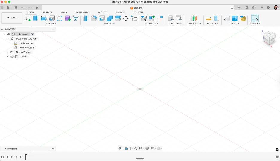
The interface is organised into several key areas. At the top is the toolbar, which changes depending on the active workspace - the workspace selector on the far left lets you switch between Design, Mesh, Render, Animation, and other environments, each loading a different set of tools. The Browser panel on the left shows a tree of all bodies, components, sketches, and construction geometry in the document, making it easy to hide, isolate, or select any element. The large central area is the 3D viewport, where the model is built and navigated - right-click and drag to orbit, middle-click to pan, and scroll to zoom. Along the bottom runs the Timeline, which is one of Fusion 360's most powerful features - every modeling operation is recorded as a step here, and you can click back to any point in the history to edit earlier decisions without rebuilding the model from scratch.
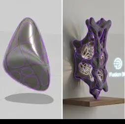
Fusion 360 was the primary 3D tool this week. The goal was to design an organic lattice form - a structure where a light source placed inside produces shadow and glow patterns through the geometry of the object itself. The design concept is a low-polygon sphere where mesh edges are converted into tubular pipes, creating an open shell that is both 3D-printable and visually distinctive.
The workflow direction was based on tutorial inspiration and references, and then refined through multiple design attempts. Based on the video inspiration, I also used Gemini to explore concept variations of how an organic shape could look before building the final modeling sequence.
Reference videos: https://www.youtube.com/watch?v=158ZpD44dq4, https://www.youtube.com/watch?v=yuJ82relaHM
Attempt 1
Based on the research from the Internet and some tutorials and video content, the process is like this. Just I want to create a regular shape and pulling and pushing the existed sphere or even make a holes. Making holes can be done by boolean technique or by removing some plates and make wall thicker. Also for creating some interesting shapes and patterns I made irregular shape by using curves and… And later I used to extrude command to cut the body.
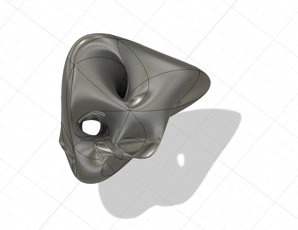
Next part is to create a mesh from existing body. The mesh command can generate very high polygon, high shapes structure, and it was a step number one after this. I want to reduce number of polygons and make it simpler. Simple shape with just simple edges is what do we need for next step.
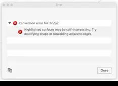
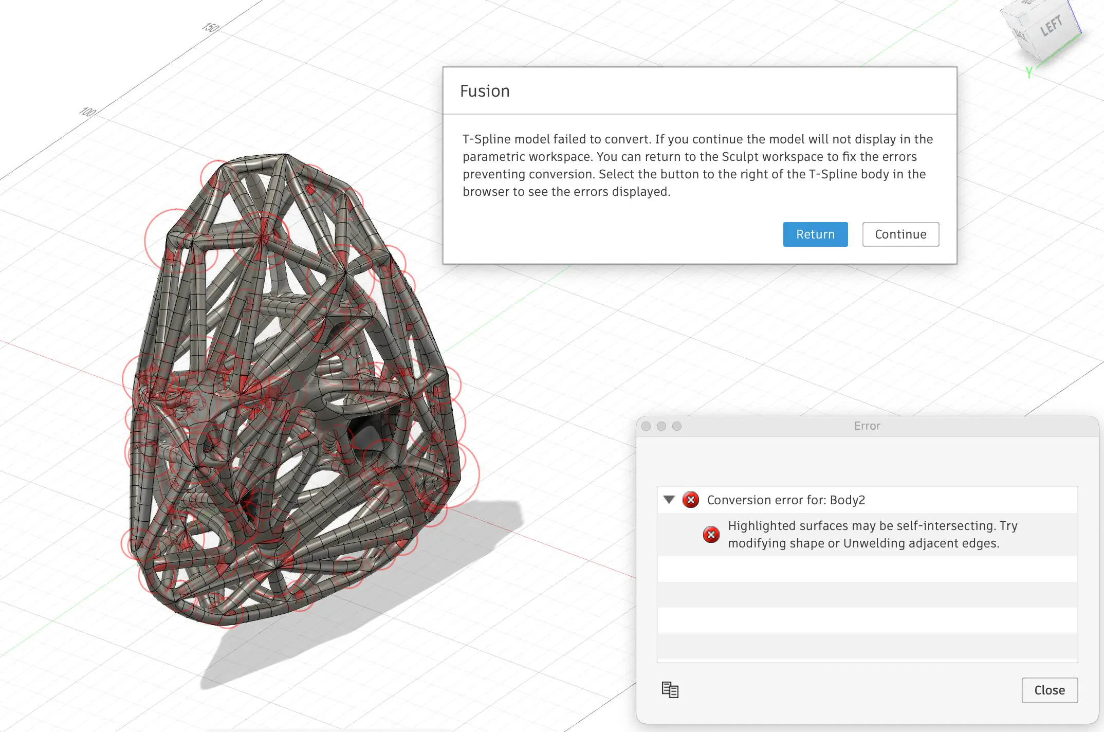
After simplifying a mesh, it was a special command, how to select only edges without selecting body, and after selecting edges, those edges can determine into some organic shapes, but in the step of saving, I got a roar that the body can't be converted. I realized that it may be some empty structures inside and I don't know how to solve this problem so I decided to make the initial shapes not so complex a bit more simpler.
Attempt 2
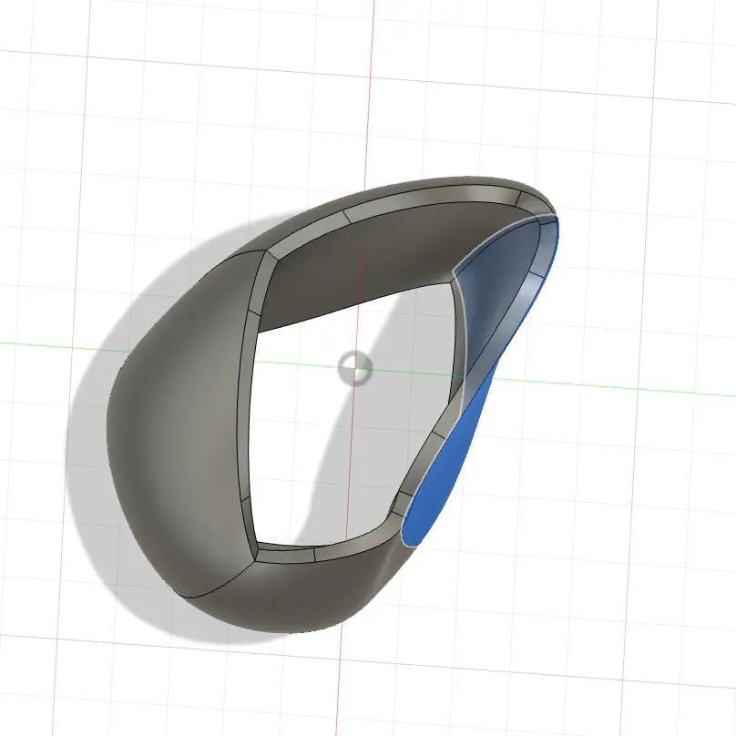
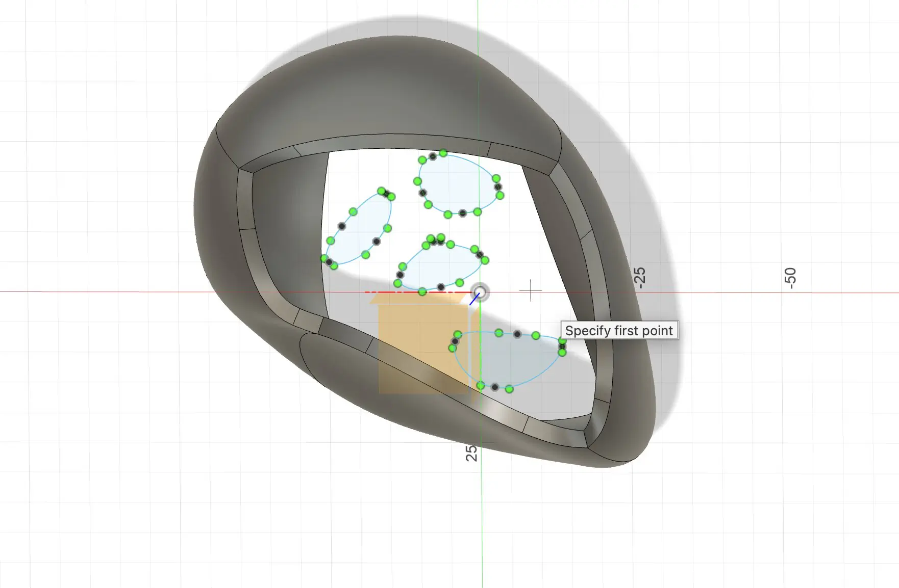
This step I decided to make shape without hollow companies and just cut the holes using extrude command. I design a simple patterns by curves to create unique shapes.
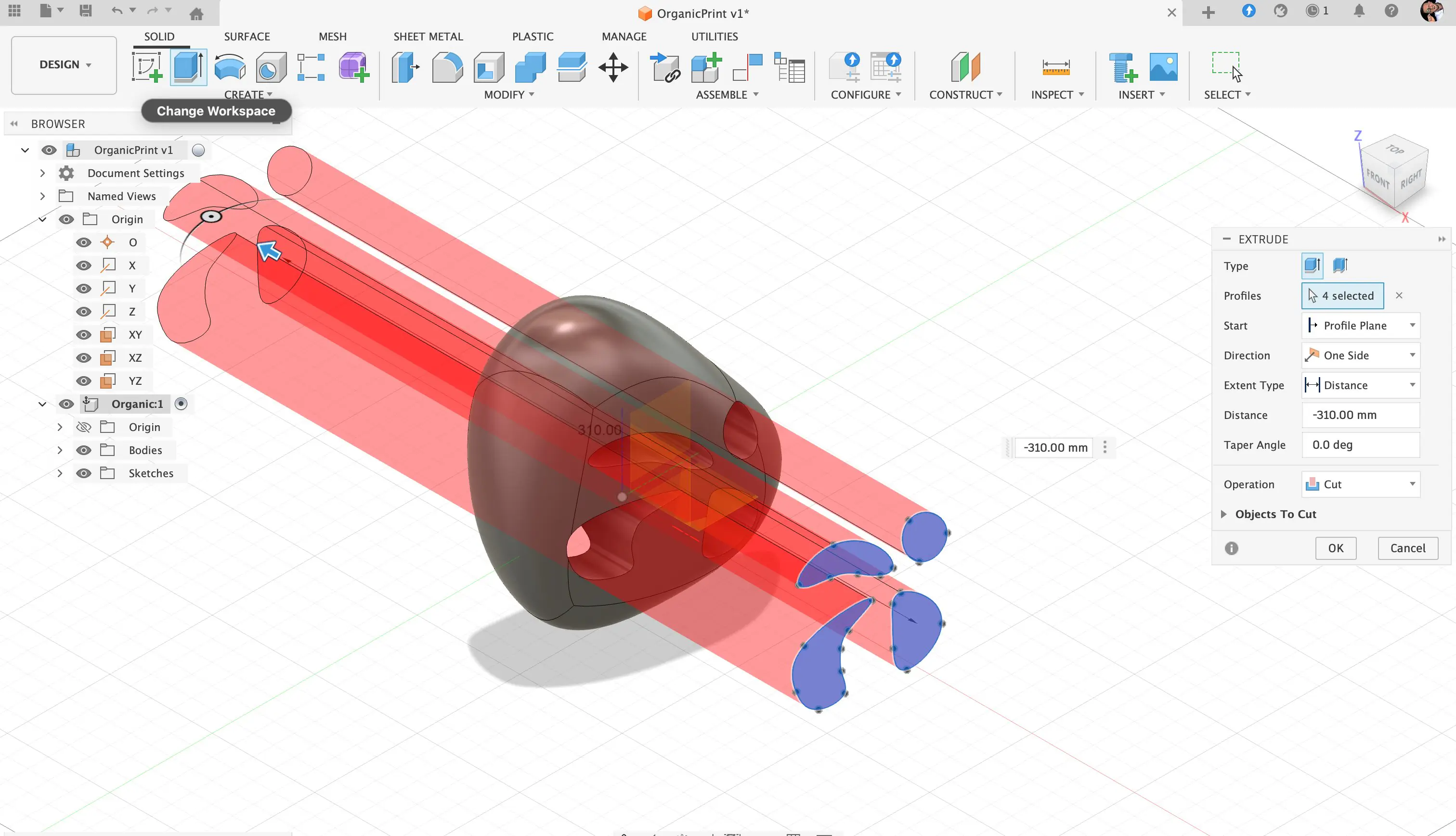
Then after cutting holes, their body can be converted into mesh body. And this mesh buddy contain a lot of polygons as in previous example, and then amount of polygons can be simplified.
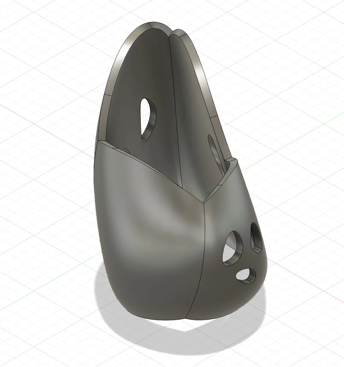
As in previous attempt after simplifying the polygons, we can select only edges and after selecting edges, we can use the pipe command to create organic shape.
Even after another type of the shape, it was the same error error, and maybe it's something but I need to learn in the future and this complex organic shape require extra attention. To make a ball will be a better solution and I can experiment with printing. Also, in the future, I can experiment more with hollow shapes and some complex joints inside the body.
Attempt 3 — Low-Poly Sphere to "Organic Joints" Lattice
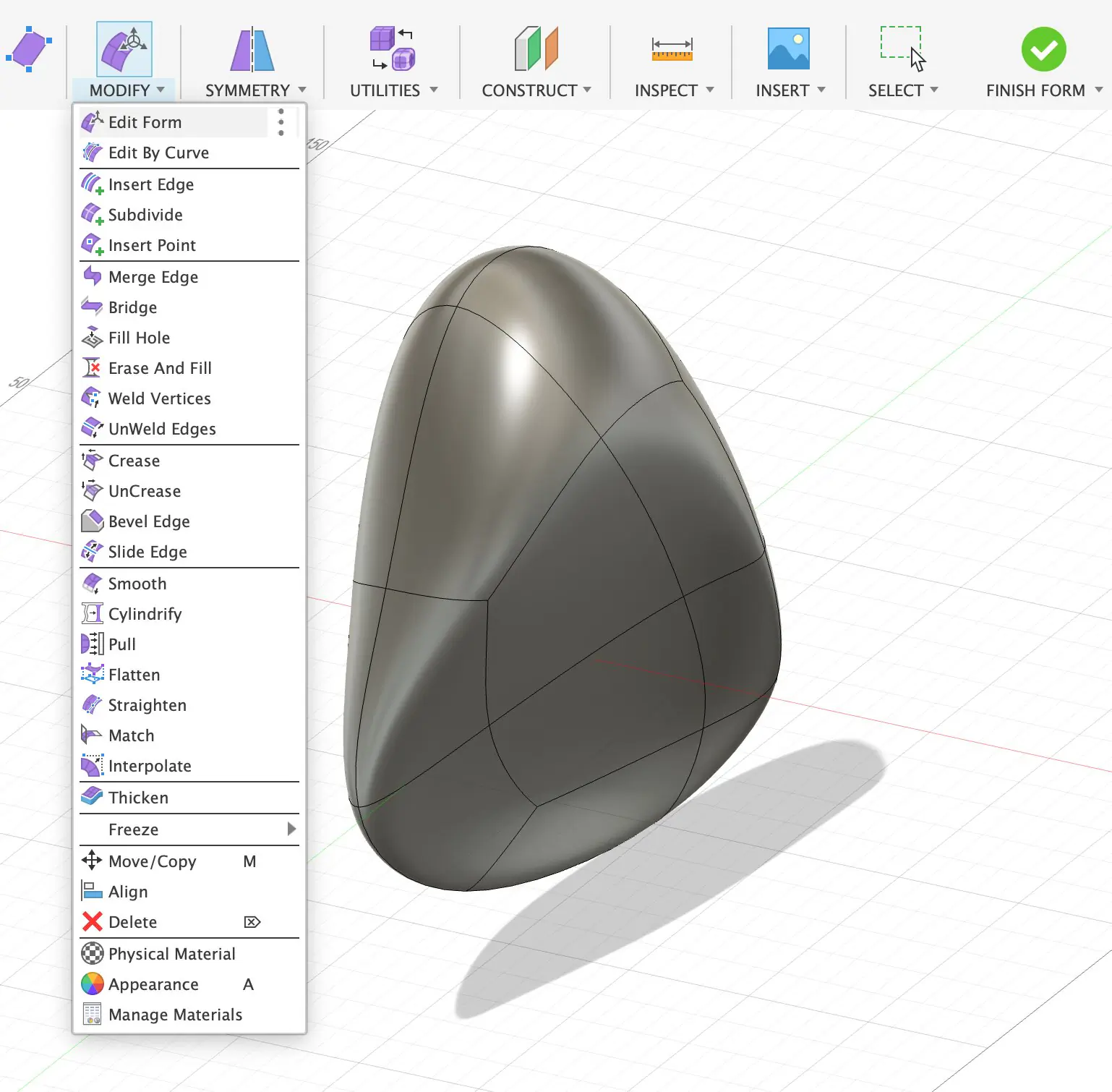
1) Why I restarted and kept the sphere "regular"
This is my third attempt, and the main decision was to avoid an irregular, chaotic base shape. In earlier tries, the sphere deformation quickly turned into a random form and the final result looked accidental. This time I treated the sphere as a controlled "base mesh," because the whole workflow depends on predictable topology later (especially when I convert edges into pipes).
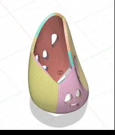
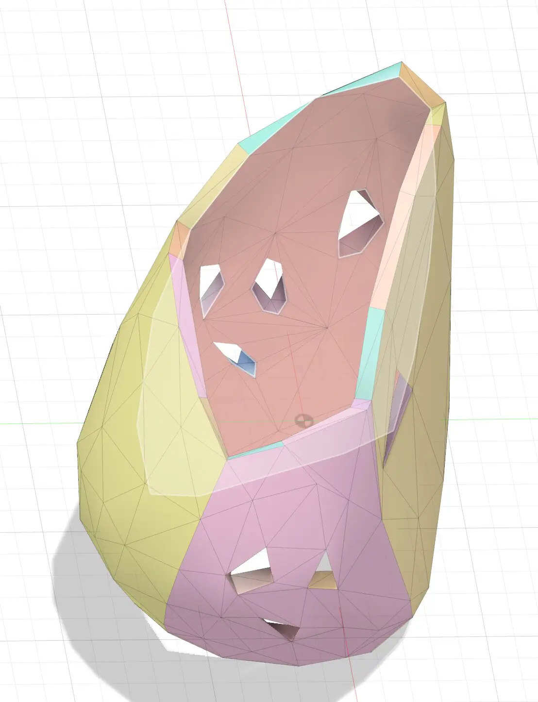
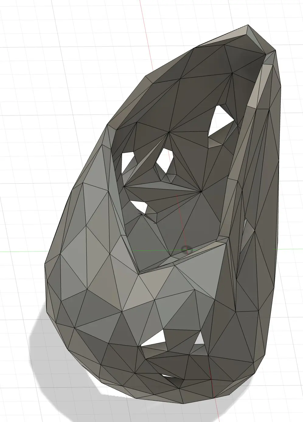
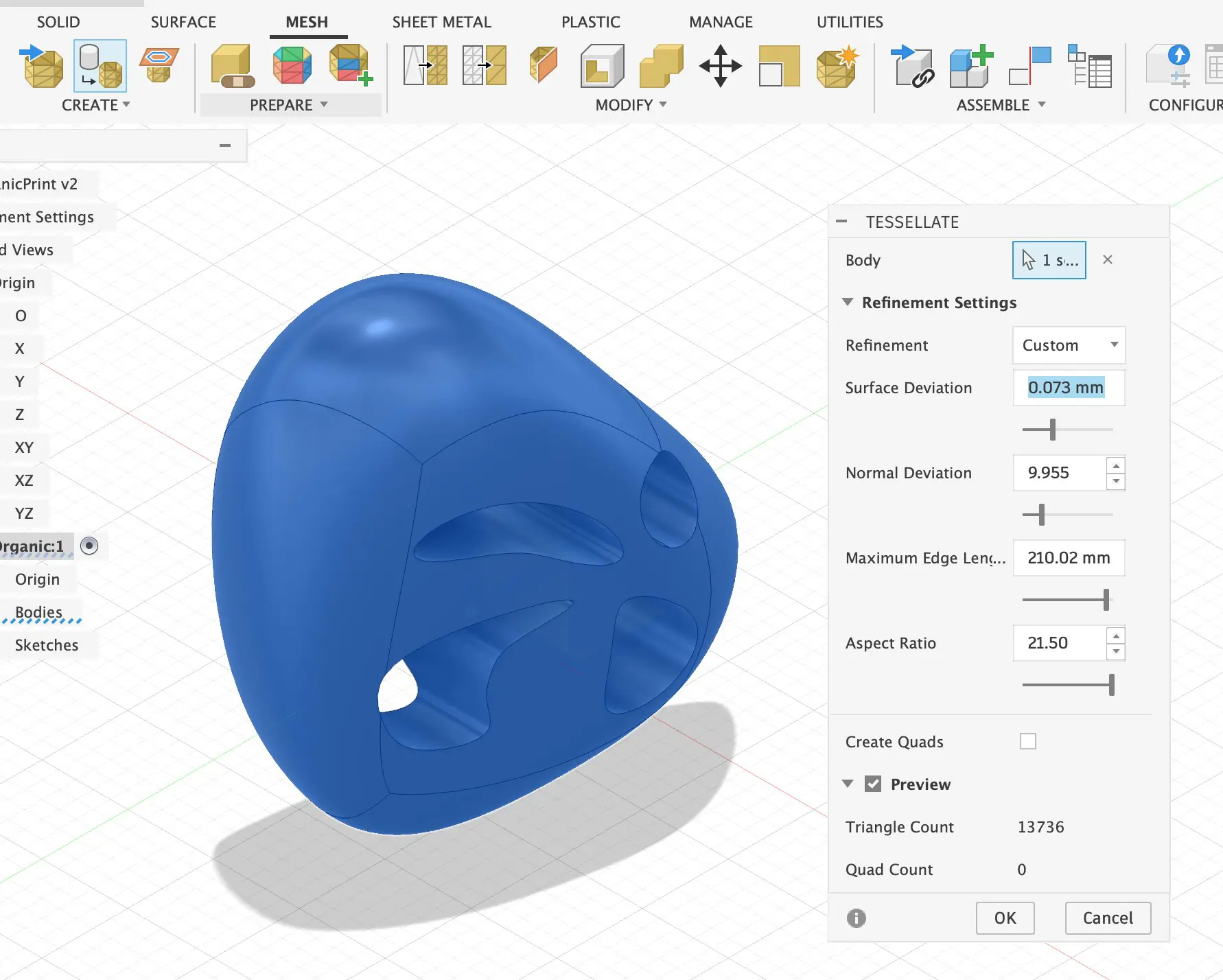
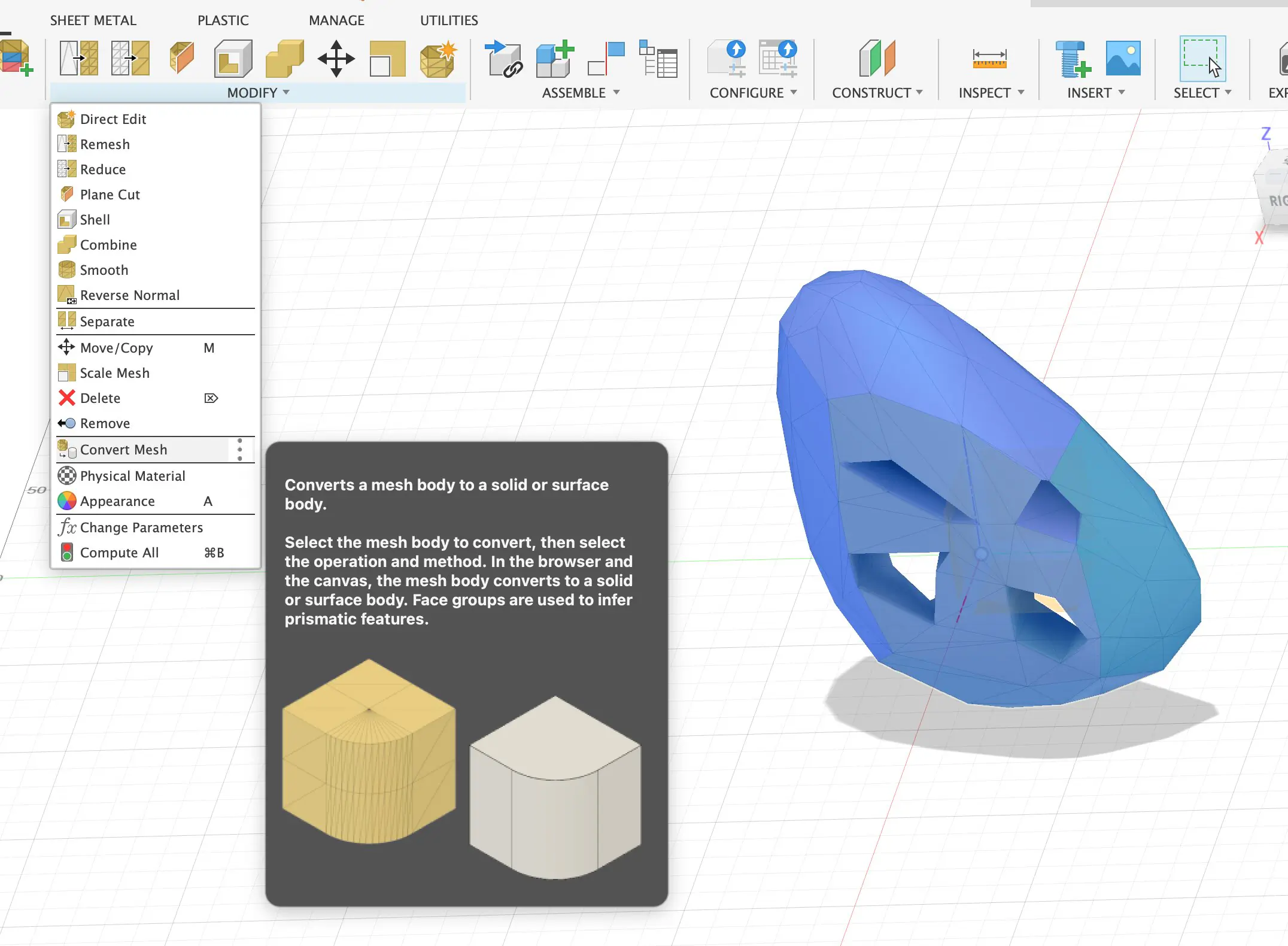
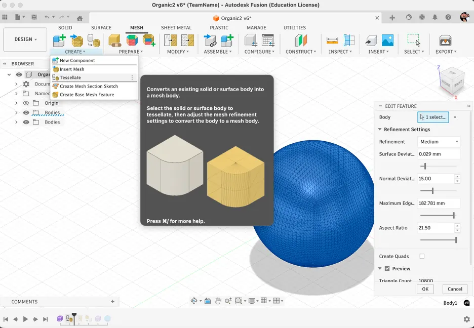
2) Converting the solid body into a mesh (and why it becomes heavy)
After the base sphere was ready, I switched into the Mesh workspace and converted the body into a mesh. The conversion produced a dense polygon surface, which is expected because curved shapes are approximated using many faces. At this point the model was too complex for the pipe-all-edges idea, so simplification became necessary.
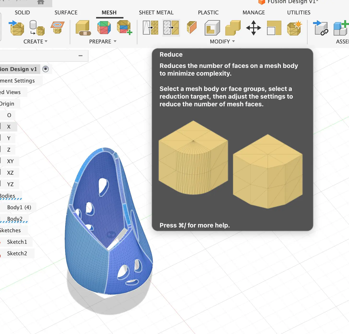
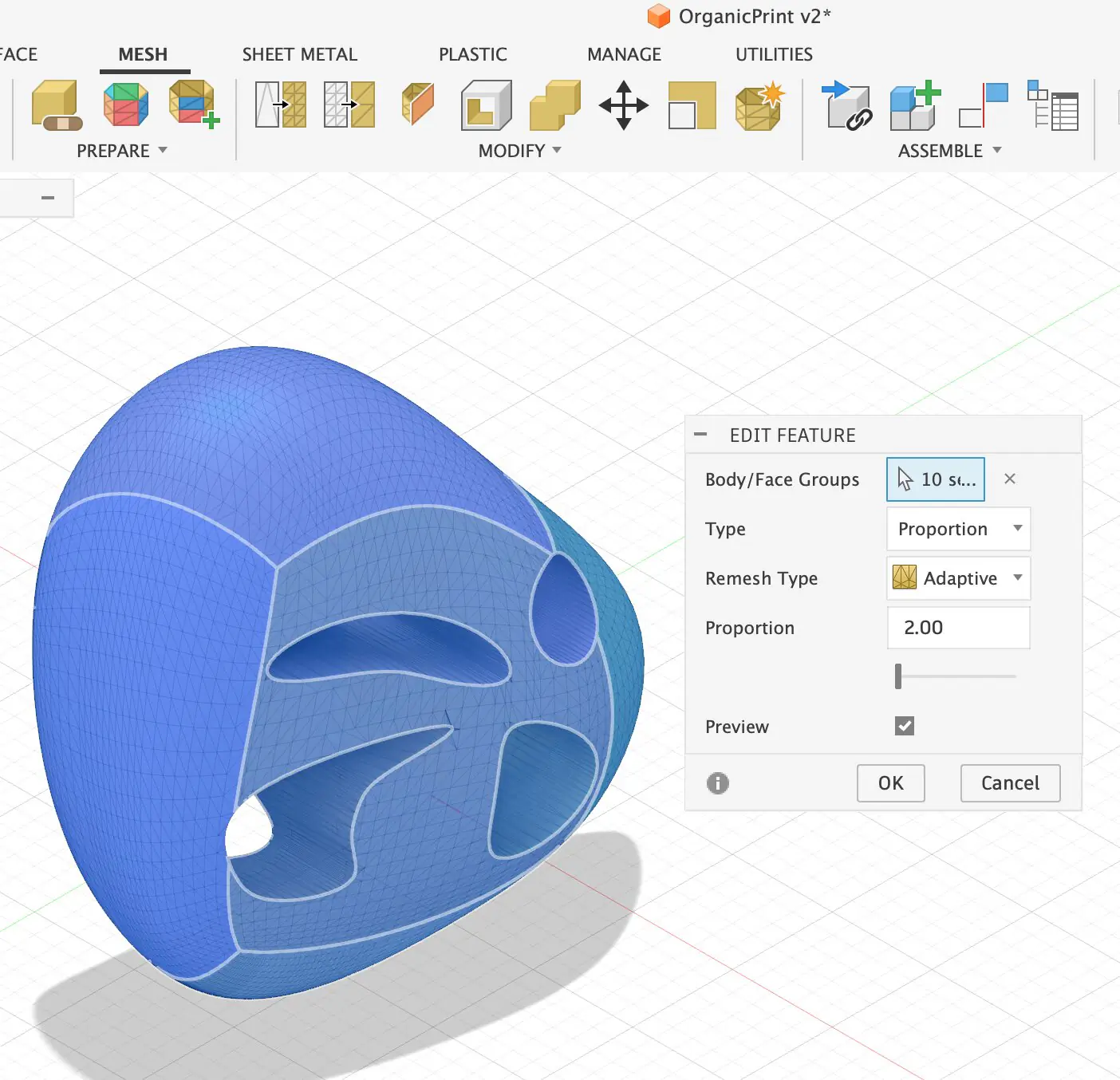
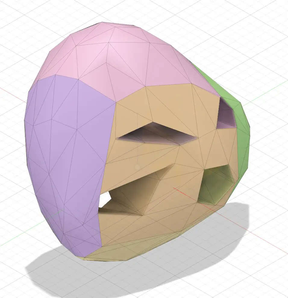
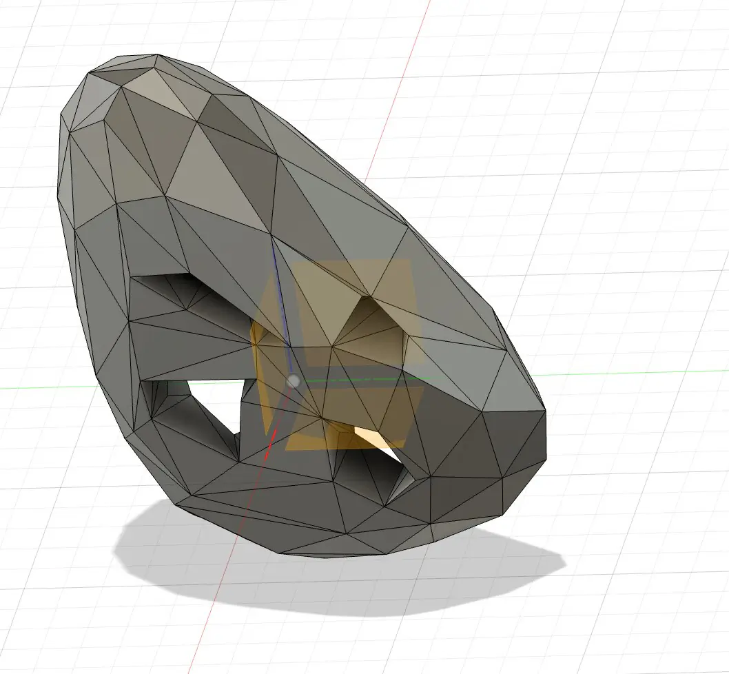
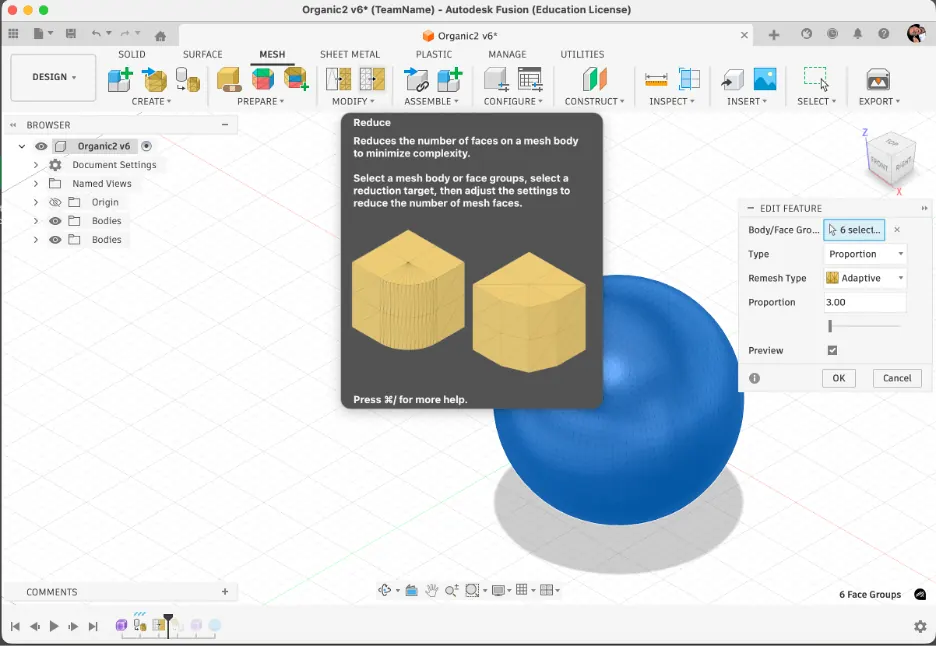
3) Reducing faces to control the "low-poly look"
The key turning point is the Reduce tool. I reduced the face count while still keeping the silhouette round enough. The goal was not to destroy the sphere - it was to intentionally create a low-poly version that still reads as a sphere. This step defines how complex the final lattice will be.
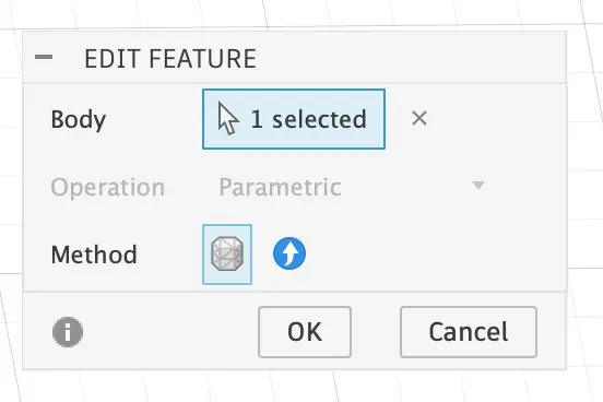
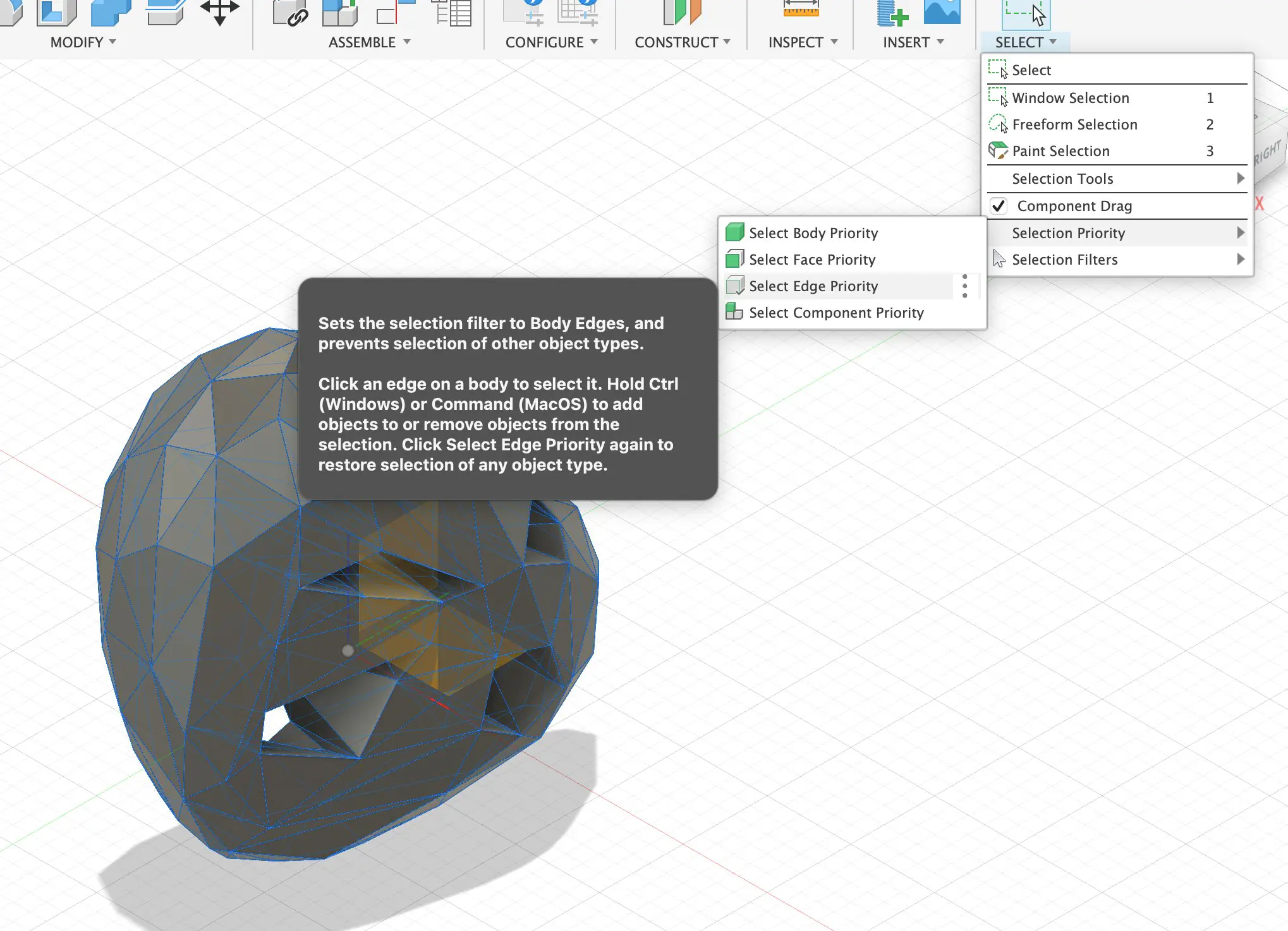
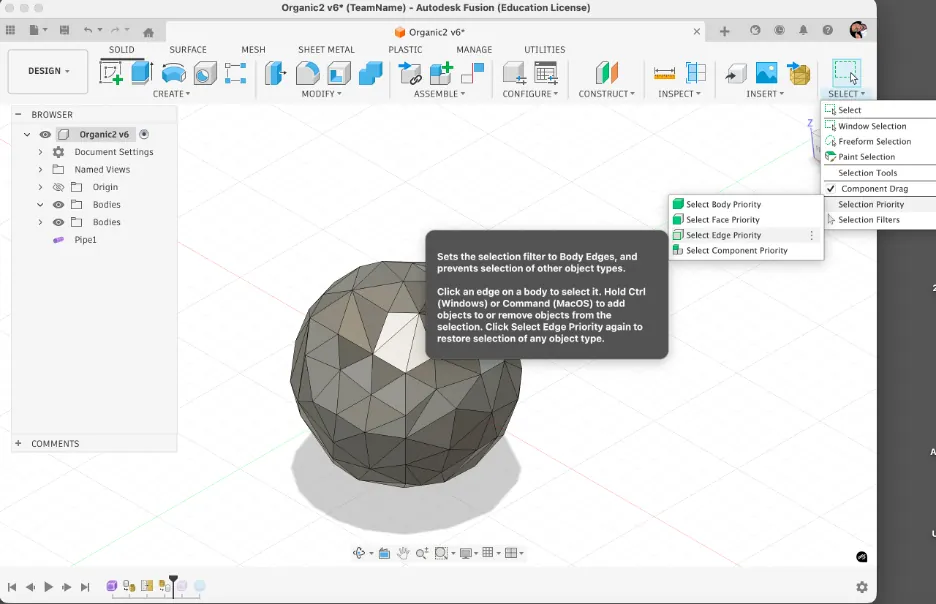
4) Switching Selection Priority to Edge Priority
To pipe the structure, I needed to select edges reliably. On complex geometry Fusion often selects faces or bodies by default. I changed Selection Priority to Select Edge Priority so that edge selection becomes faster and more consistent.
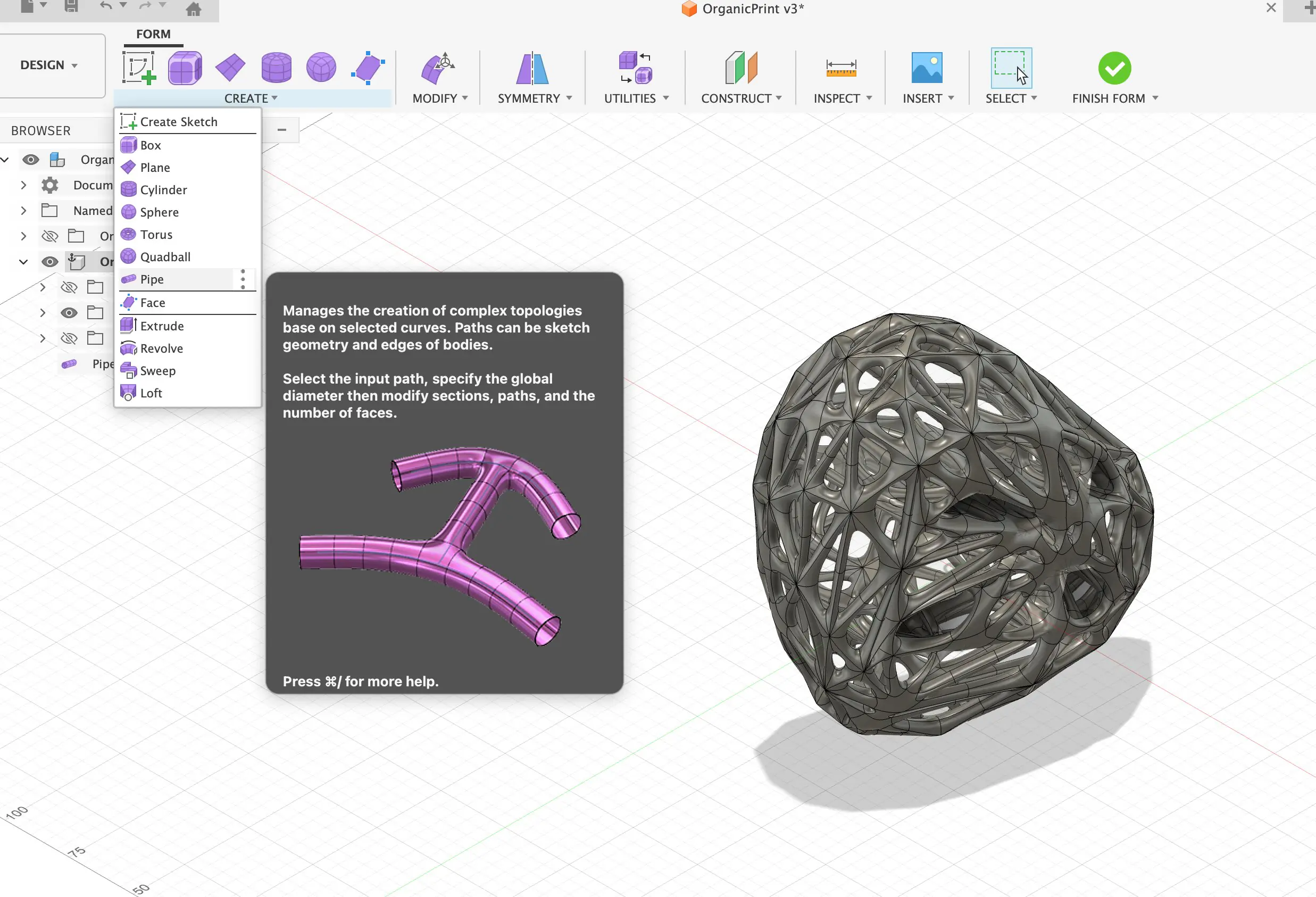
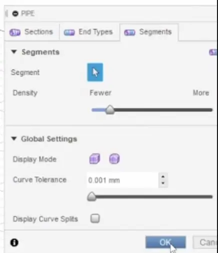
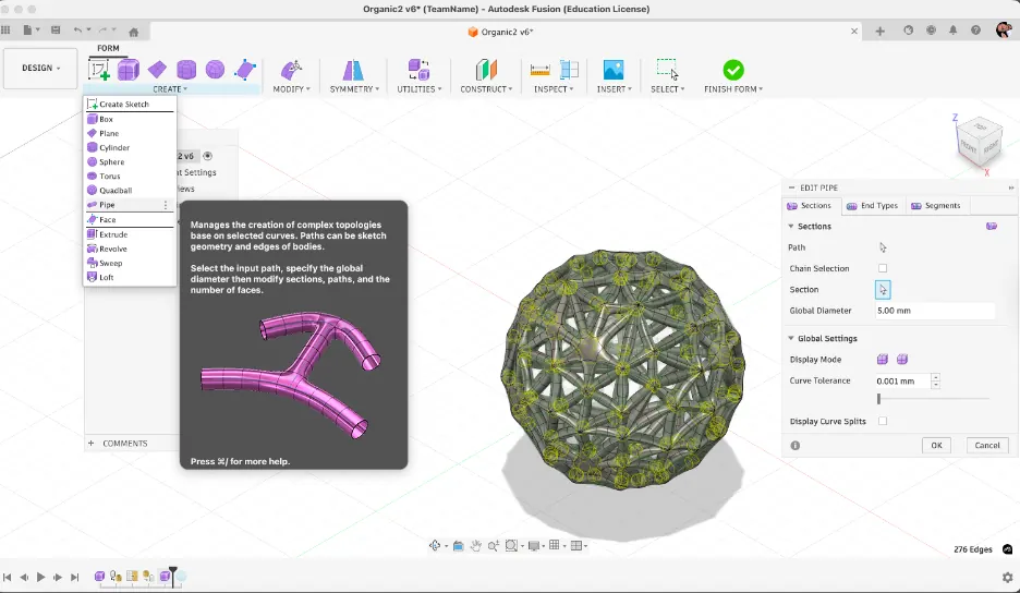
5) Turning the mesh edges into pipes (creating the "joint network")
With edge selection under control, I used Pipe to generate tubes along the selected edges. Conceptually, I removed faces from the design and kept only the edge skeleton as a connected structure. I created the pipes as a New Body to keep the workflow non-destructive and easy to iterate.
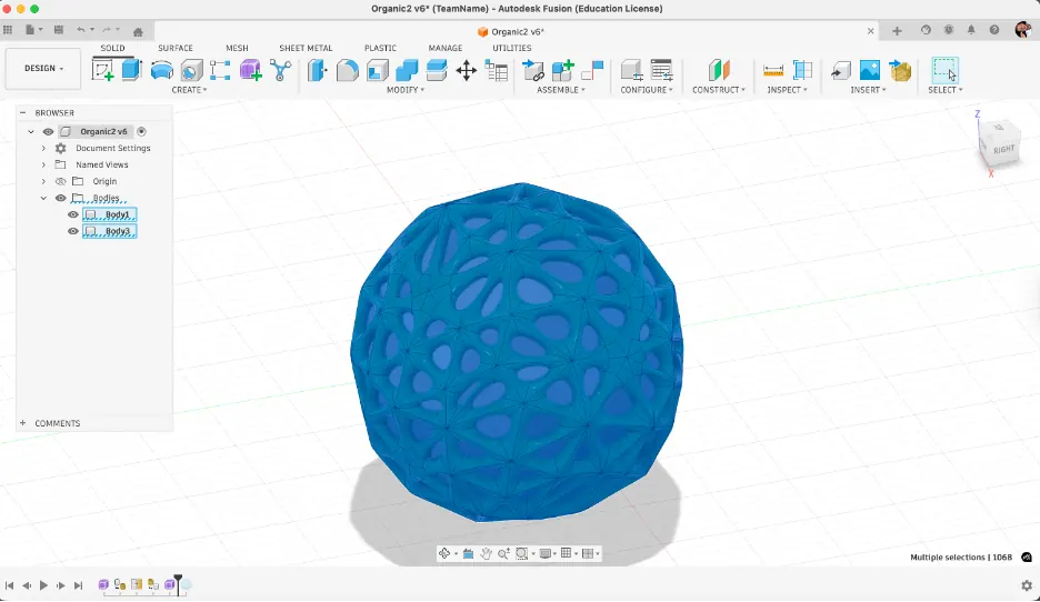
6) Separating bodies, applying appearance, and adding an inner sphere
After piping, I had two bodies: the low-poly mesh sphere (reference) and the pipe lattice (final structure). I hid the mesh sphere and kept only the pipes. Then I added a smaller sphere inside to make the design more interesting and applied different appearances for clearer visual separation.
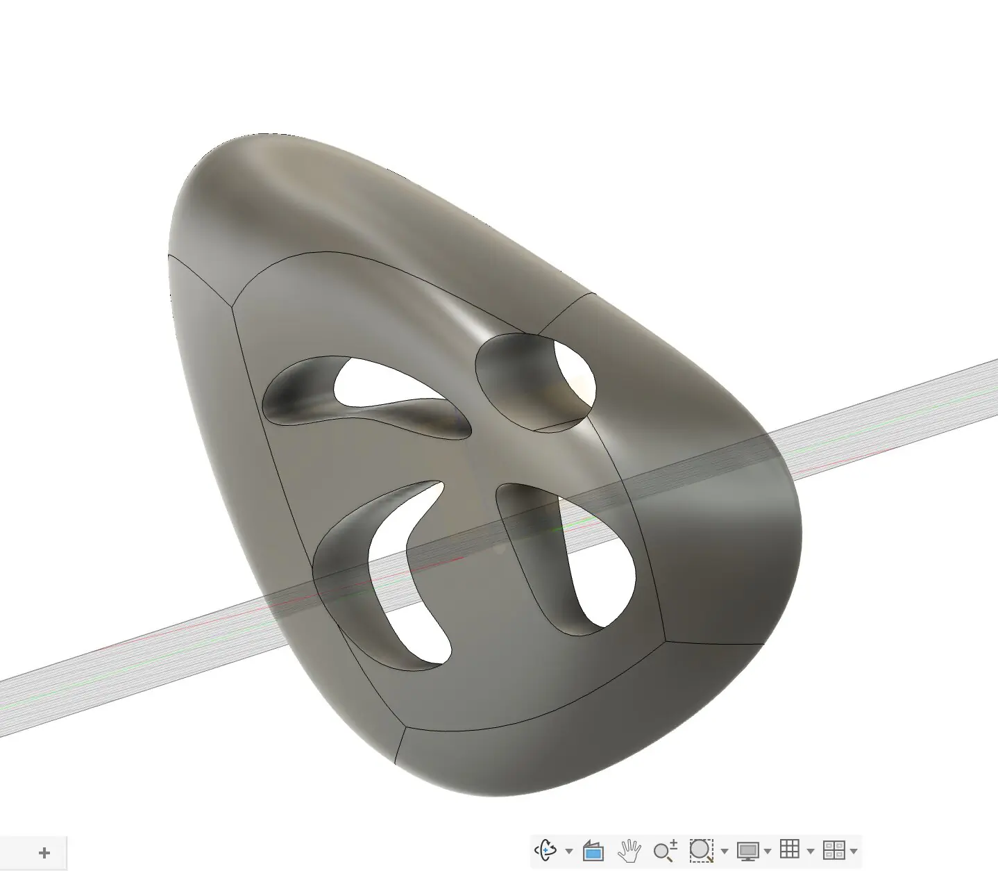
7) Section Analysis to validate the inside structure
Finally, I used Section Analysis to cut through the model and check how the lattice and inner sphere read internally. This is both a visual presentation tool and a validation step before exporting for fabrication.
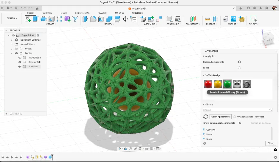
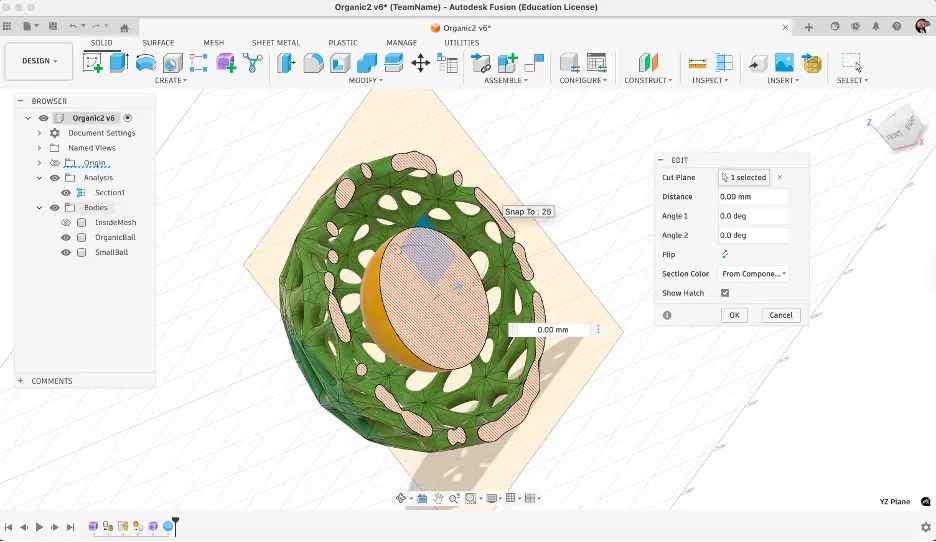
Image Converting and Compression
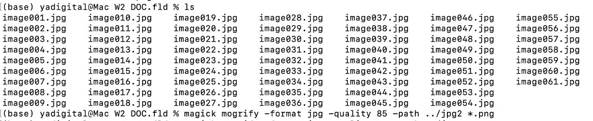
I compressed all images before uploading to keep the website fast and responsive. I used ImageMagick for batch processing of images.
Method Used
Tool: ImageMagick (command-line tool)
Command: magick mogrify -format jpg -quality 85 -path compressed *.{png,jpg,jpeg}
Settings
- Format: JPG (converted from PNG and other formats)
- Quality: 85 (good balance between quality and file size)
- Additional optimization: Removed metadata with
-stripflag
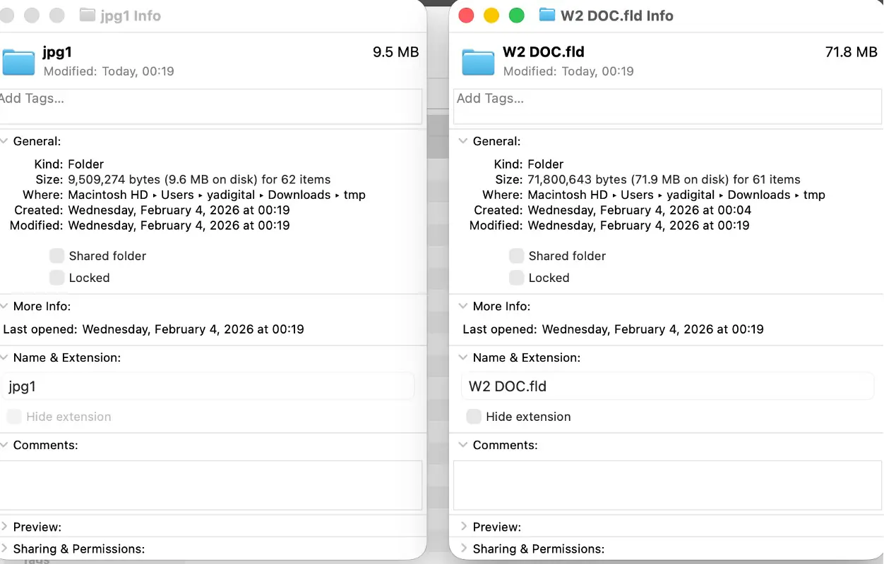
This compression method significantly reduced file sizes while maintaining good visual quality for web display. Original high-resolution files are kept separately for archival purposes.
Video Converting and Compression
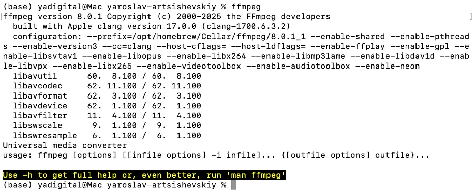
I tried video converting and compression before with online services and GUI apps, but this time I used command line with FFmpeg.
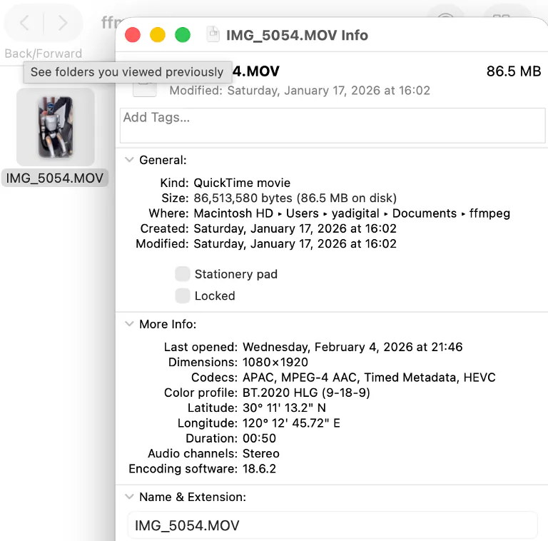
Tool: FFmpeg
Goal: convert a MOV file to MP4 and reduce size for web upload.
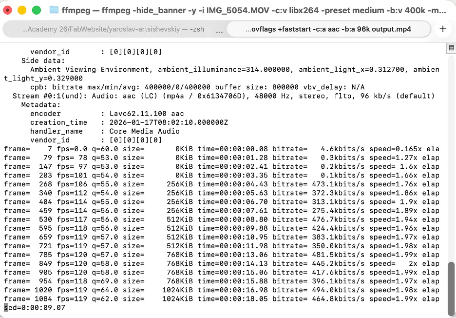
First Command (High Compression)
ffmpeg -hide_banner -y -i "input.MOV" -c:v libx264 -preset medium -b:v 400k -maxrate 400k -bufsize 800k -pix_fmt yuv420p -movflags +faststart -c:a aac -b:a 96k "output.mp4"Command Breakdown
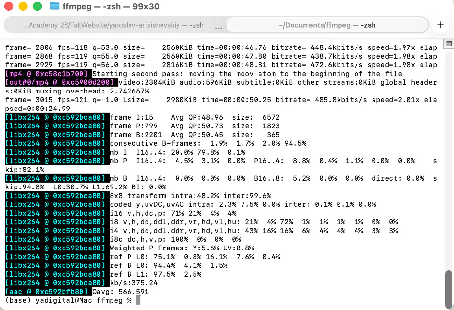
ffmpeg: runs FFmpeg.-hide_banner: hides startup/version banner.-y: overwrites output file automatically.-i "input.MOV": input video file.-c:v libx264: H.264 video encoder.-preset medium: balance between encoding speed and compression.-b:v 400k: target video bitrate.-maxrate 400k: caps bitrate spikes.-bufsize 800k: controls bitrate buffering behavior.-pix_fmt yuv420p: compatible pixel format for most players.-movflags +faststart: places metadata at file start for web playback.-c:a aac: AAC audio codec.-b:a 96k: audio bitrate."output.mp4": output filename.
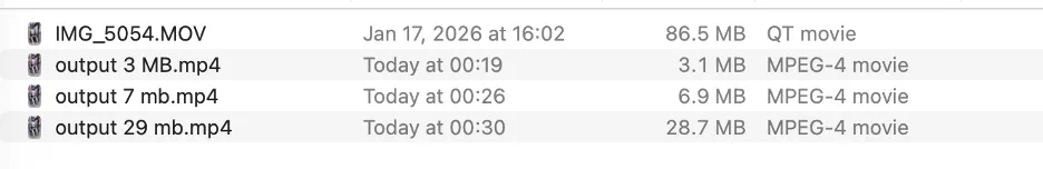
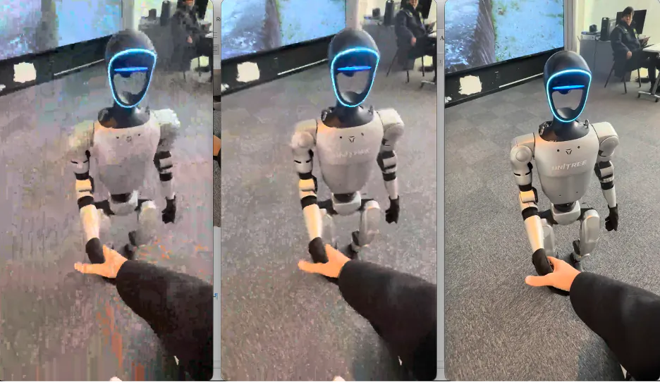
This command produced a very small file (~3 MB), but quality was too low.
Better Quality Command
ffmpeg -hide_banner -y -i "input.MOV" -c:v libx264 -preset medium -b:v 1M -maxrate 1.2M -bufsize 2M -pix_fmt yuv420p -movflags +faststart -c:a aac -b:a 128k "output.mp4"-b:v 1Mincreased video bitrate.-maxrate 1.2Mallowed slightly higher peaks.-bufsize 2Mgave smoother bitrate control.-b:a 128kimproved audio quality.
Result was around 6 MB, with better quality but still not ideal.
CRF Method (Quality-Based)
ffmpeg -hide_banner -y -i "input.MOV" -c:v libx264 -preset medium -crf 28 -pix_fmt yuv420p -movflags +faststart -c:a aac -b:a 128k "output.mp4"-crf 28uses constant quality (lower value means better quality and larger file).- No fixed video bitrate limit, so size depends on scene complexity.
- Useful when quality consistency is more important than exact file size.

Design Files
- Download video file (output 3 MB.mp4)
- Download GIMP source (Gimp_light.xcf.zip)
- Download Illustrator source (Nature logo.ai.zip)
- Download Rhino STL (rhino8!.stl.zip)
- Download Fusion 360 source (Attempt 3 Organic Ball.f3d)
Week 2 Reflection
This week was the first time I worked across multiple CAD tools in a structured way, and the main thing it taught me was that choosing the right tool for the right task matters as much as knowing how to use the tool itself. I started with GIMP and Illustrator to understand the difference between raster and vector workflows in practice, not just in theory. Working with Illustrator's Boolean operations, particularly Pathfinder Unite, Offset Path, and Shape Builder, made it clear how vector geometry is built up from simple primitives, which is a logic that carries directly into 3D modeling as well.
The shift to 3D was where most of the learning happened. In Rhino, I understood how surface-based modeling works by building a form from curves and profiles rather than pushing and pulling a solid. The Loft and ArrayPolar commands gave me a feel for how complex symmetrical geometry can be constructed efficiently from a small number of base curves. Fusion 360 took longer to get right, but the failure in the first two attempts was itself useful - it showed me that mesh topology is not forgiving of irregular starting geometry, and that a clean, predictable base shape is a prerequisite for any downstream conversion operation. Once I understood that, the third attempt using a regular sphere, reducing the polygon count, and piping the edges worked as intended.
The biggest practical lesson of the week was about workflow logic: each modeling step either opens up or closes off the options available in the next step. Starting simple and adding complexity gradually is more efficient than trying to build a complex form from the beginning. This is something I will apply directly in the coming weeks when developing the lamp shade model further toward fabrication.