07 Computer-controlled machining
Assignment
- Group assignment:
- Complete your lab's safety training
- Test runout, alignment, fixturing, speeds, feeds, materials and toolpaths for your machine
- Document your work to the group work page and reflect on your individual page what you learned
- Individual project
- Make (design+mill+assemble) something big
Overview:
Previously, my experience with interlocking furniture was limited to manually cutting cardboard, which was often simple and rough. This week, I learned a lot of new digital fabrication techniques. A major highlight was completing the entire workflow—from 3D design to CAM toolpath generation—seamlessly within Fusion 360, which proved to be incredibly convenient.
I also discovered the concept of Dogbone joints, which was entirely new to me. Since a circular CNC bit cannot cut sharp 90° internal corners, I used the Nifty Dogbone plug-in in Fusion 360. It made adding these necessary clearances incredibly simple and automated, ensuring my press-fit joints could be fully seated. I chose 15mm Birch Plywood for my project to ensure structural stability for a "large-scale" object, using a 6mm Flat End Mill.
Group Assignment
Group link: this page documents the group assignment.
Workflow :
1.Safety Training & PPE Preparation➡ 2. Characterization: Speeds, Feeds & Setup ➡ 3. Comb Test for Tolerances
Safety Training
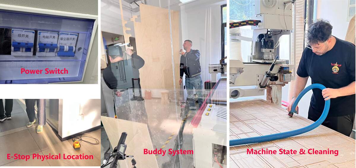
Pre-Operation & Risk Management:
• Supervision & Training: I learned that only trained individuals are allowed to operate the machine. Untrained people must never work on the CNC without professional supervision.
• The "Buddy System": I must always operate the Machine with a partner. Having a second pair of eyes to double-check the setup and files is crucial for catching potential errors before they become dangerous.
• Machine State & Cleaning: The machine must be powered off during loading. Cleaning the bed and rails is a critical fire prevention measure, as accumulated wood dust is highly flammable.
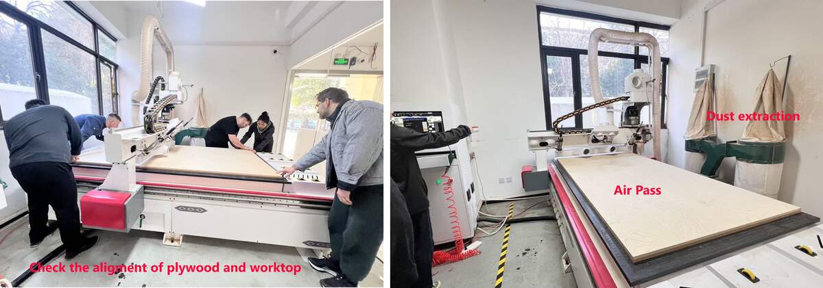
• Air Pass (Path Verification): Before the actual cut, I performed an "Air Pass" (Z-zero 50mm above the board) to verify the movement and ensure the spindle wouldn't hit any screws or clamps.
• Pre-Cutting Safety Check: Turn on the vacuum switch to activate the dust extraction system before the machine begins cutting, to guarantee continuous dust removal throughout the entire process.
• E-Stop Physical Location: I identified the physical location of the Emergency Stop button and ensured it was placed in an easily accessible spot (e.g., outside the glass enclosure) for instant reaction.
Operational Safety Rules:
• PPE & Attire: Eye and ear protection are mandatory. I must wear closed-toe shoes at all times and ensure long hair is tied back to prevent it from being caught.
• No Gloves & Rail Safety: Never wear gloves while operating the machine, as they can be caught by the spinning spindle and pull your hand in. Similarly, never place hands on the rails, as the machine can move unexpectedly in any direction.
• Material Security: I must ensure the plywood is properly secured before cutting. I am also aware of the risk of small parts coming loose after being cut; if not secured with Tabs, they can be thrown forcefully by the bit.
• No Unattended Operation: Never leave the machine running unattended. A spinning tool generates significant friction and heat, posing a fire risk.
Fire Prevention & Technical Optimization:
• I learned to minimize fire risks by using correct chip loads, sharp bits, and double-checking all toolpath files. I must always be prepared to pause or stop the cut immediately if anything sounds or looks incorrect.
Lab Material Inventory:
- 6mm x 2440mm x 1220mm Plywood (8 sheets)
- 15mm x 2440mm x 1220mm Plywood (6 sheets)
- Test Tool: 6mm Flat End Mill
Characterization: Speeds, Feeds & Setup
I used the group characterization test to record the cutting values that worked on our lab CNC when cutting 15mm plywood. These values are machine-specific and should not be copied directly to another CNC without testing.
| Parameter | Value / Result | Note |
|---|---|---|
| Spindle Speed | 20000 RPM | Value checked during the machine-side operation. |
| Feed Rate | 20000 mm/min | Actual cutting feed used in our test. |
| Test Stepdown | 12mm | This value belongs to the group characterization test, not the final stool contour setting. |
| Tool Diameter Compensation | Effective cutting diameter: 6.1mm | The nominal end mill was 6mm, but the measured effective cutting width was about 6.1mm. I used this 0.1mm difference as a practical compensation reference. |
⚠️ Caution:
The 12mm stepdown here refers to the characterization test. In the final stool CAM, I later used a 15mm single-pass contour cut-through. That setting was more aggressive and only worked on our lab CNC after testing the material, tool condition, machine rigidity, and simulation. It should not be treated as a universal CNC setting.
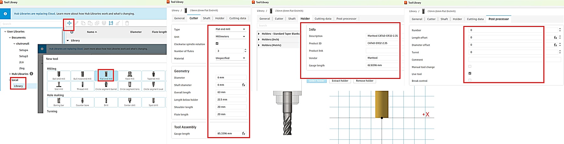
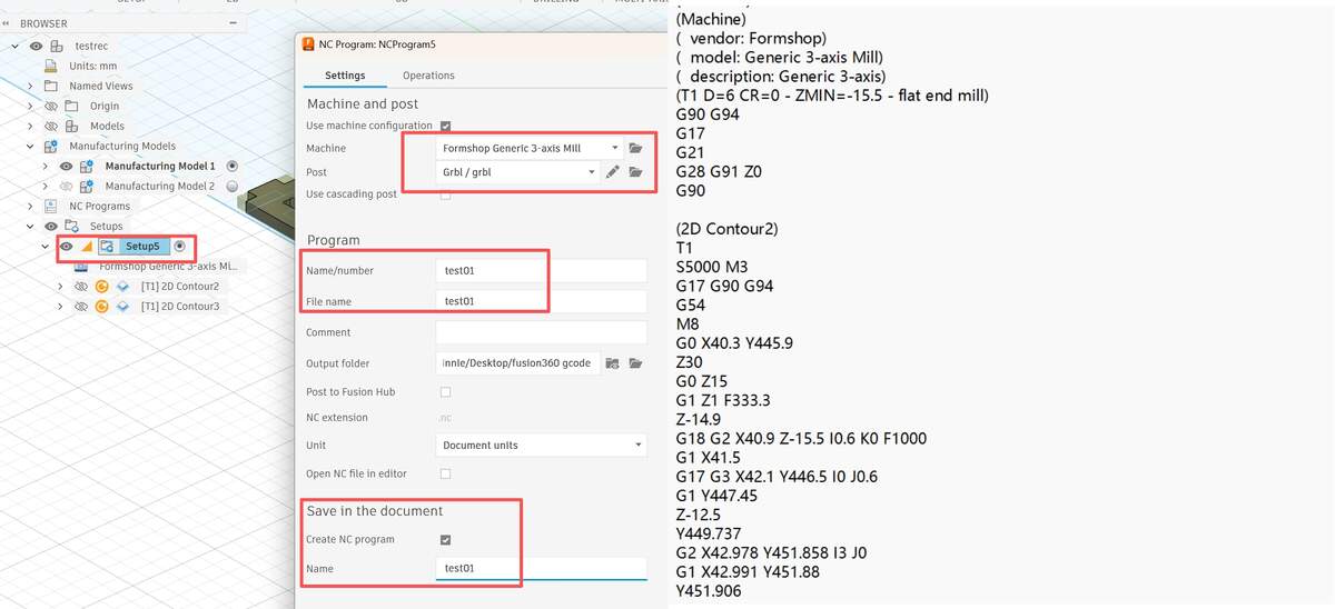
Setup: Post Processing, Machine Definition, Tool Library
Overview: Within the Manage tab of the Manufacture workspace, I configured the Machine, Tool, and Post Libraries. By manually adding parameters based on our specific lab equipment,I configured the machine, tool, and post libraries in Fusion 360 so I could simulate the toolpath before machining.
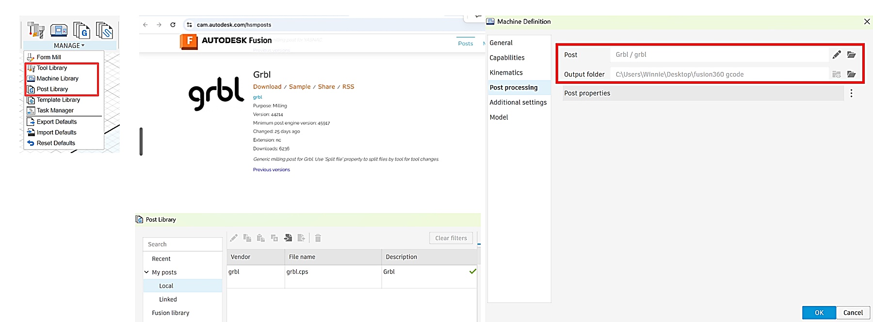
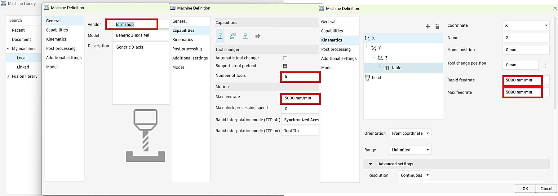
Note about the 5000 mm/min value:
In Fusion 360, I entered 5000 mm/min as a machine-definition and simulation reference for post-processing. However, the actual movement and cutting speed were controlled by the CNC machine's own operating software. Therefore, I used the machine-side settings as the final reference, not only the Fusion 360 machine library.
Comb Test for Tolerances
Overview: To verify the actual fit and ensure safety,I made a comb test before cutting the stool parts. The goal was to check the slot fit, confirm the tolerance, and make sure the toolpath and machine setup were safe before cutting the full object.
Testing file Workflow: CAD Parametric Design ➡ Edit Manufacturing Model: Nesting & Dogbone ➡ Setup & WCS ➡ Toolpath & Simulation ➡ Export Post Process
CAD Parametric Design:In Design mode, I designed a set of test slots ranging from 14.7mm to 15.3mm with 0.1mm increments based on the 15mm plywood thickness.
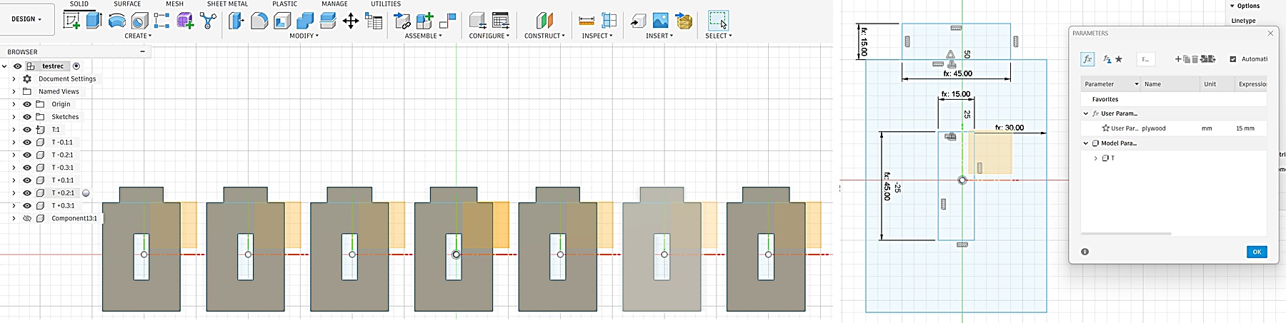
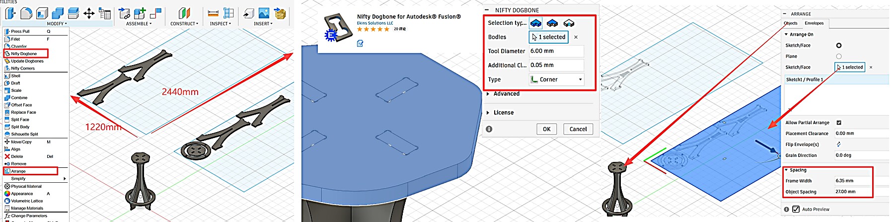
Manufacturing Model Optimization:
- Create Nesting Surface: Sketched a rectangle matching the board size as a base in the Manufacturing Model.
- Component Arrangement: Arranged test models on this surface to ensure nesting efficiency and grain alignment.
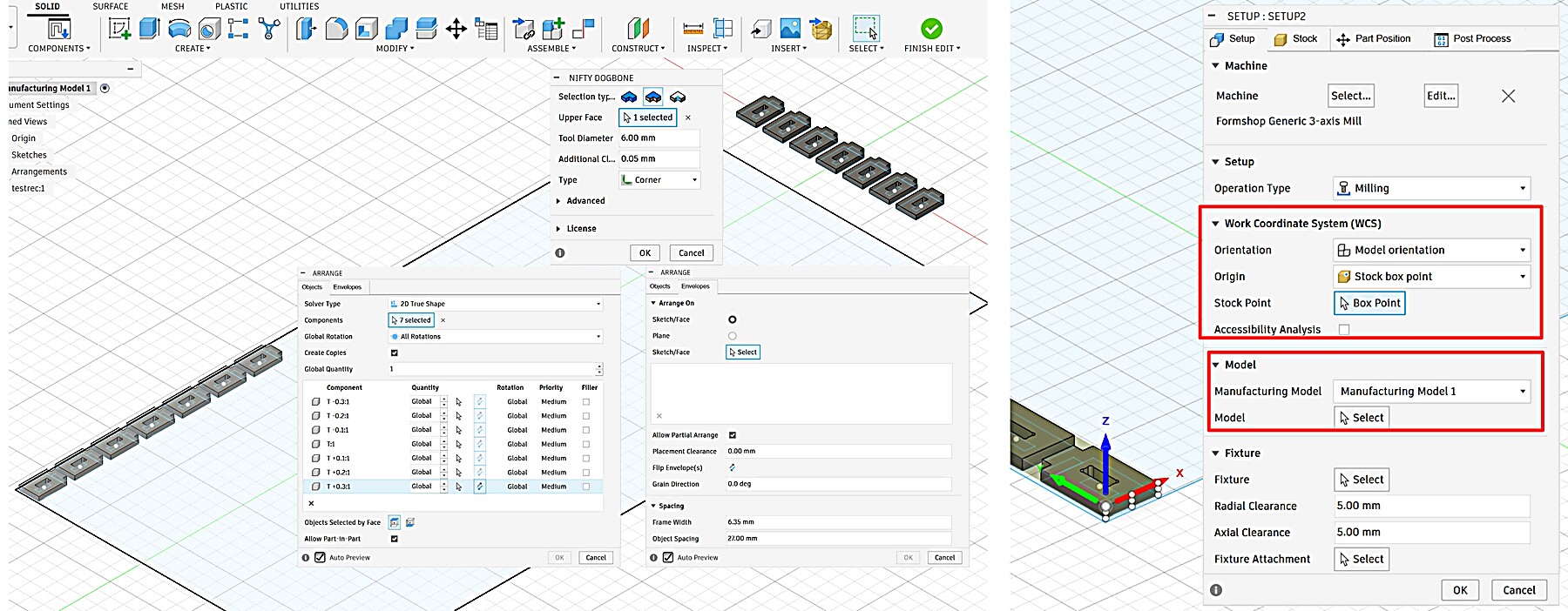
- Add Dogbones: Applied Dogbones to the arranged models without altering the original design to ensure clean corners.
Setup & Alignment: Created a new Setup based on the nested surface, accurately setting the Work Coordinate System (WCS) to match the physical board 2440x1220mm placement.
Toolpath & Simulation:
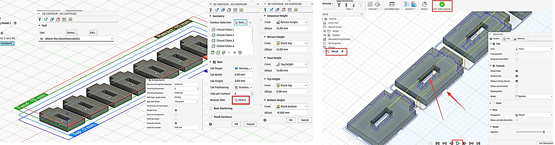
- Tab Settings: Added Tabs to the outer boundaries to prevent small part movement during cutting.
- Precision Control: No Tabs were added inside the slots to ensure flush mating surfaces for accurate results.
- Simulation: Performed a full simulation to verify the toolpath boundary and check for potential collisions.
Export Post Process
Right-click the Setup in the browser bar and select Post Process.
- Configuration: Select the GRBL post processor to match the lab's CNC workflow.
- Output: Check units (Metric/mm), then click Post to export .nc or .gcode files for the machine console.
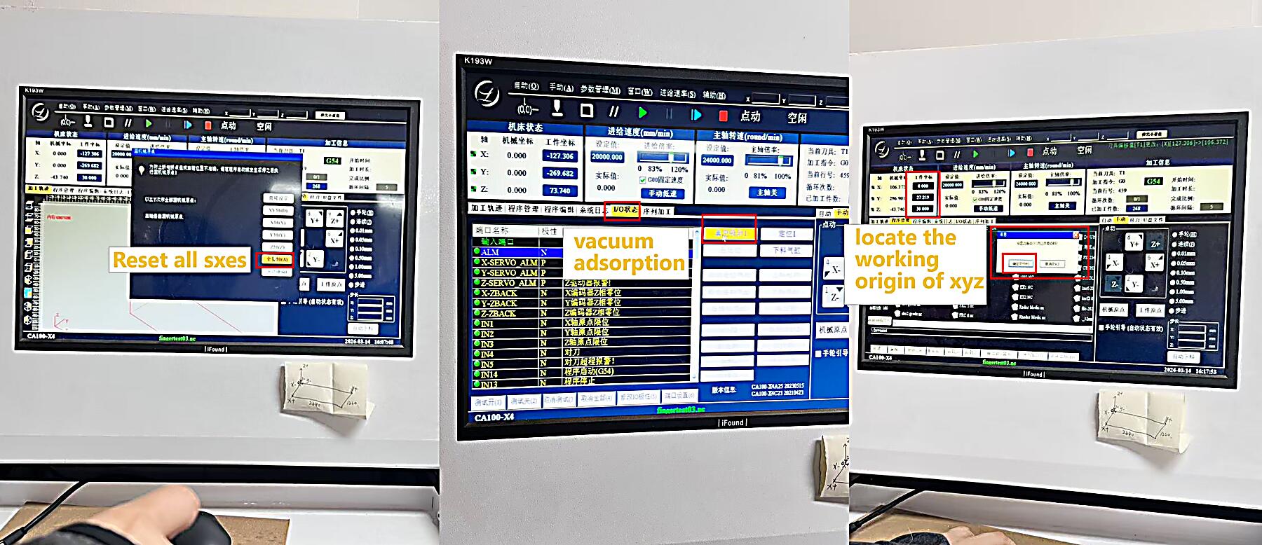
Machine Preparation & Operation Workflow:
Reset Axes all 0➡ Vacuum & Check ➡ Manual WCS Locating ➡ Draw Frame ➡ Sim & Cut
- Environment Initialization: Reset the coordinates of all axes in the control program. Turn on the vacuum pump and manually press the edges of the wooden board to confirm that it is firmly adsorbed and there is no warping.
- Positioning: Move the spindle to the origin corresponding to the layout, and manually zero the X and Y axes. Use a tool setter or manual mode to set the Z - axis height. Note: If the plywood is uneven or warped and vacuum suction isn't enough, use screws or nails in safe zones to physically flatten and secure the board, ensuring consistent cutting depth and preventing movement.
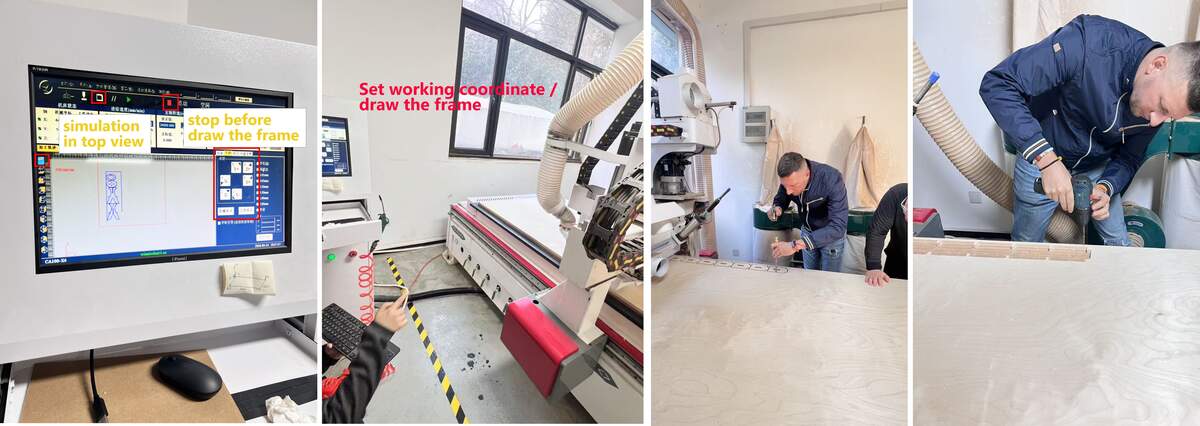
- Physical Range Verification (Frame): Activate the Frame function, visually observe and confirm that the tool head's movement trajectory is completely within the physical boundaries of the wooden board.
- Operation and Part Retrieval: After setup, carry the keyboard to the external physical pause button. Press F9 to start and F10 to pause. Maintain a constant watch from a safe corner, never leave the machine unattended, and be ready to pause for safety. After cutting, extract the test piece to verify 14.9mm as the optimal fit.)
Result :
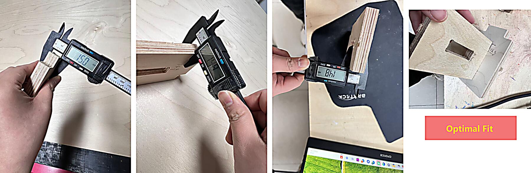
- 14.9mm: ✅ Optimal Fit
- Physical Measurement: Observed a material deviation of 0.1-0.2mm in thickness on the sides.
- Fit Validation: Despite slight material unevenness, the joint sections achieved high precision with no significant thickness or clearance errors.
Individual Assignment
Design Phase (Parametric Design for 15mm Plywood)
Workflow: Define Gap Variable & Parameters ➡ Sketching & Modeling➡ Create Manufacturing Model ➡ Apply Dogbones➡ Arrange/Nesting
Design Phase: I designed two Bar Stools using parametric modeling in Fusion 360. The height of each bar stool is set at 700 mm. For the seat part, I designed two different sizes to create a distinction. To ensure the stools are sturdy enough for daily use, I used 15 mm Plywood.
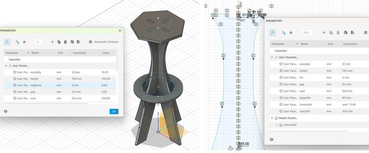
- Tolerance Design: Given the actual thickness variations of the 15mm plywood, I set the thickness parameter to
Material_Thickness = 15mm. - For the tolerance test, I changed the size of the slots connecting the seat and the legs to 14.9 mm. However, I didn't modify the tolerance of the slots on the legs because there is more contact and friction area at the slots on the legs, and a size of 1 5mm is more appropriate.
- Corner Treatment: Using the Nifty Dogbone plugin, I applied T-Bone fillets based on the measured effective cutting diameter. Although the end mill was nominally 6mm, the test showed an effective cutting diameter of about 6.1mm, so I used this value as the reference for tool diameter compensation and dogbone clearance.
- Arrange/Nesting: I used the
Arrangetool to lay out the components within the 2440mm x 1220mm workspace.
CAM & Toolpath Planning
Workflow: Create Setup➡ Set WCS Origin➡ 2D Contour ➡ 2D Pocket ➡ Simulation➡ Post Process
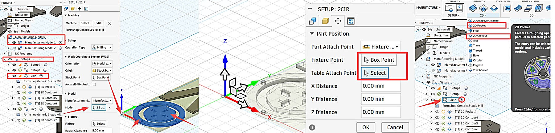
2D Contour
2D Pocket
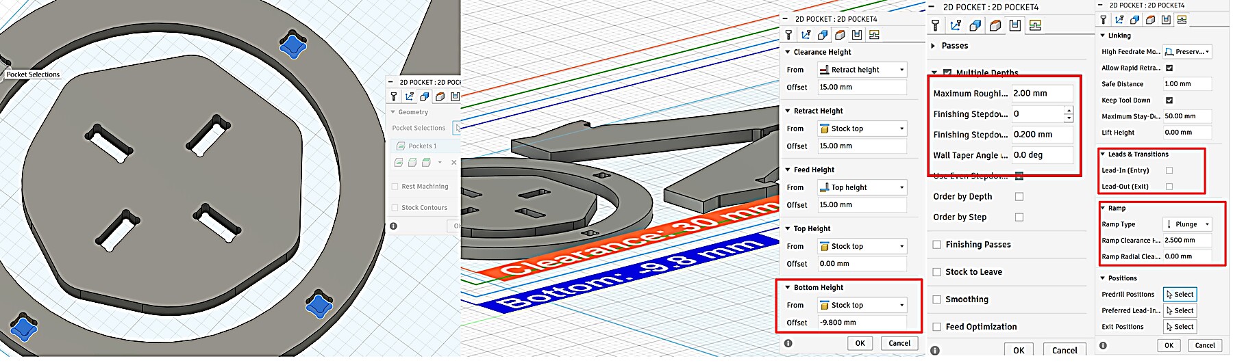
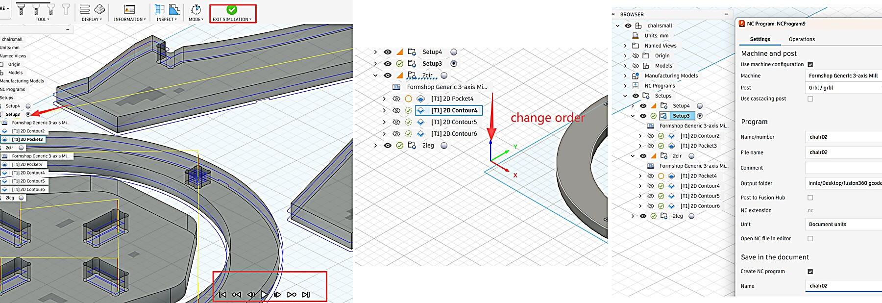
Simulation & Post Process
Critical Error Analysis
Through iterative testing and consultation with Gemini, I identified two critical areas for error prevention:
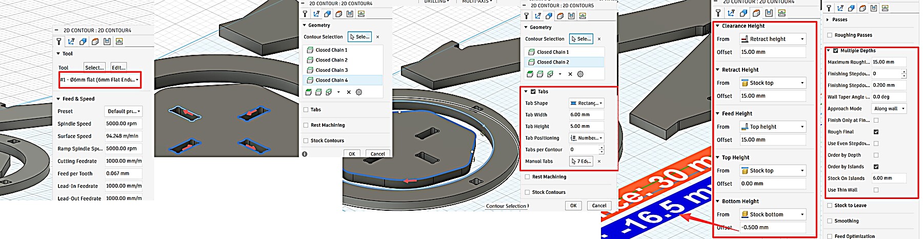
| Operation | Goal | Bottom Height Setting | Rationale |
|---|---|---|---|
| 2D Pocket | Partial Depth | From: Selected Contour(s) Offset: 0mm |
Follows the CAD model depth (9.8 mm) relative to the top surface. |
| 2D Contour | Full Cut-through | From: Stock Bottom Offset: -0.5mm |
Never calculate from the Top! Referencing the Bottom ensures a clean cut regardless of stock thickness. |
| - Processing Order: 2D Pocket must run BEFORE 2D Contour. If the outer profile is cut first, the part becomes loose, causing vibration or displacement when attempting the inner pocketing. |
Specific Toolpath Parameters
- 2D Pocket (Inner Grooves):
- Stepdown / Cut-through: The final outer 2D Contour was set as a single 15mm cut-through. This is an aggressive setting. It worked on our lab CNC only after the group test, simulation, and checking the machine rigidity and tool condition. I would not copy this setting directly to another CNC machine or material without testing first.
- Result: The 5mm depth was cleared in 3 passes, resulting in a very smooth pocket floor and efficient chip removal.
- 2D Contour (Outer Profile):
- Stepdown: Single Pass (15mm). In this test, the single-pass contour cut worked after checking the machine rigidity, tool condition, and simulation. This setting should not be copied without testing the material and machine first.
- Tabs: Added 5mm x 3mm Tabs to secure the parts during the final cut.
AI Use Note
For this CAM issue, I used Gemini only as a checking tool. I sent screenshots of my Fusion 360 parameter page, marked the area I was unsure about, and asked about the pocket height setting because I already suspected the problem was related to that direction.
I am setting up a 2D Pocket operation in Fusion 360. Here is a screenshot of my parameter page. I think the problem may be related to the pocket height setting. Can you explain how Top Height, Bottom Height, Selected Contours, and Stock Bottom affect the toolpath, and why the toolpath may float above the material or cut to the wrong depth?
Gemini did not give me the correct answer directly. I still had to adjust the CAM settings several times and run the Fusion 360 simulation after each change. It helped me understand the principle, but the final setting came from my own simulation and testing.
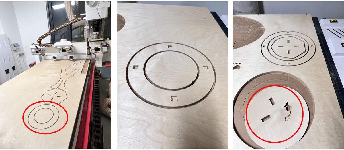
Machining & Assembly
Workflow: Cutting ➡ Manual Fix ➡ Sanding ➡ Assembly
I have placed the mechanical settings in the group assignment. The content regarding parameter modifications in the assembly part has been presented in the previous text.
Critical Reflections on Failures
- Pocket Reference Error:
Initially set Pocket Bottom to
Stock Bottom, causing the tool to "float" above the material. Corrected it to referenceSelected Contours. - Processing Order Error:
Ran Contour before Pocket. Once the part was detached, it shifted during pocketing, causing a mis-cut.
- Lesson: Always Pocket before Contour.
- Dimension Mismatch:
The leg slots didn't align with the footrest due to a CAD inspection oversight.
- Solution: Performed a manual saw cut to fit the parts.
Manual Fix
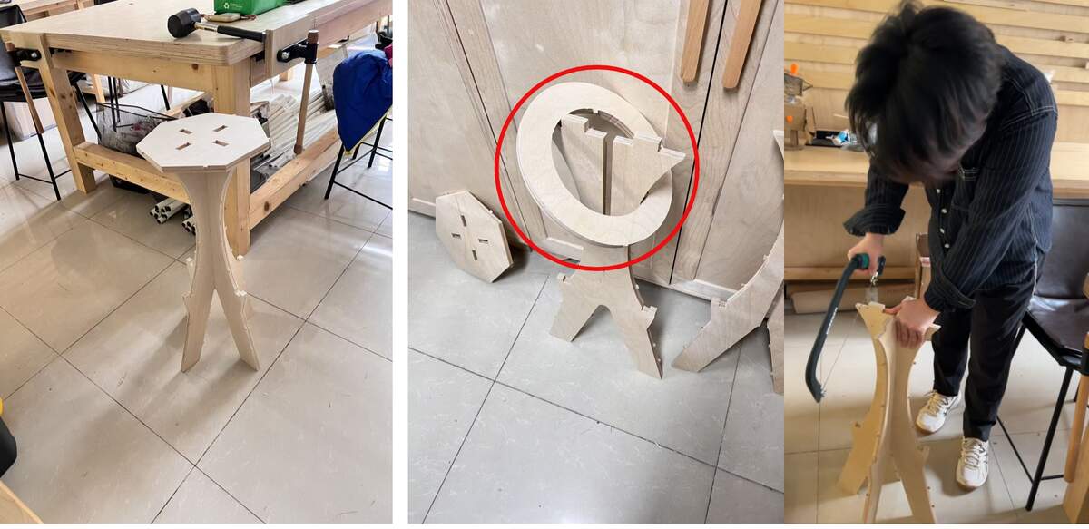
Sanding & Assembly
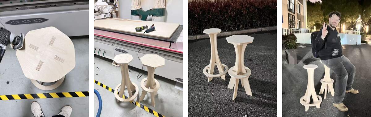
Final
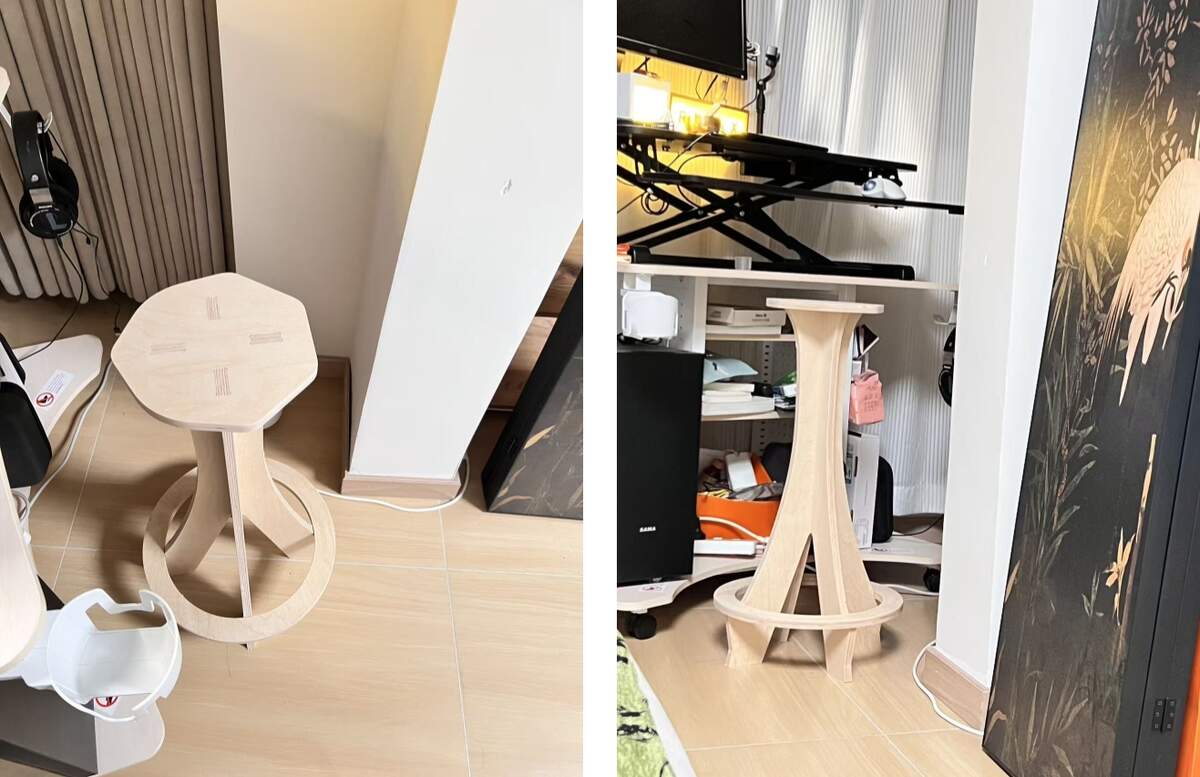
Perfect!
File
Conclusion
Conclusion
This week I completed the workflow from Fusion 360 design to CAM setup, CNC cutting, manual fixing, sanding, and assembly. The main problems came from the pocket height reference, the cutting order, and one missed CAD alignment check.
After correcting the pocket reference and manually fixing the leg-to-footrest alignment, the stool could be assembled and used. The final fit was stable enough after sanding.
Main lessons:
- Check whether the bottom height is referenced from the model, selected contour, stock top, or stock bottom.
- Cut internal pockets before the final outer contour.
- Always run simulation and check physical assembly before milling the full board.