Final Project Process
This is the organized base version of the original process page. It keeps the original order, original images, and original video, but the writing is adjusted to show the actual project progress: early research, tests, problems, fixes, and fabrication steps.
System Overview
Smart Cushion is composed of three connected layers:
- Form layer → angled foam + center cutout for body support
- Sensing layer → two FSR sensors for pressure balance and sitting stability
- Feedback layer → warm LED breathing-like light controlled by XIAO ESP32-C3
interaction loop: body posture → pressure sensing → stability evaluation → light rhythm → body relaxation
The system is designed to translate physical sitting stability into a slow visual rhythm for short screen-free rest.
What Will It Do?
Smart Cushion is a pressure-sensing cushion for short screen-free rest. It combines supportive form design, left and right pressure sensing, and warm breathing-like light feedback.
The form design is the first part of the interaction. The angled foam surface gently lifts the pelvis, while the center cutout gives the legs and feet more space. Together, they support a more comfortable and naturally upright sitting state.
This form does not force the user into a fixed posture. Instead, it helps the body sit more comfortably and settle into a more stable state before the sensing and light feedback start.
This form does not force the user into a fixed posture. Instead, it supports a more relaxed and stable way of sitting, making it easier for the body to settle before the light interaction begins.
When the user sits down, the warm LED gives soft feedback. When the pressure becomes more balanced and stable, the cushion enters the breathing-light stage.
The warm light then guides the next part of the interaction through repeated fade-in and fade-out changes. The user does not need to look at a screen or use an app. They sit on the cushion, follow the low warm light rhythm, and slow down for a short rest after screen-based work.
The warm light guides the next part of the interaction through regular fade-in and fade-out changes. The light slowly becomes brighter and dimmer in a repeated cycle, giving the user a simple visual rhythm to follow.
The user does not need to look at a screen or use an app. They sit on the cushion, let the body become stable, follow the low warm light rhythm, and slow down for a short rest after screen-based work.
The light interaction starts from the body:
sitting detected
-> left / right pressure values are read
-> pressure balance and stability are checked
-> body becomes more settled
-> warm breathing-like light starts
-> user follows the light rhythm
-> body and attention slow down
-> short screen-free rest begins
In this prototype, the breathing-like rhythm is controlled in firmware as a tunable parameter. The intended breathing reference is a slow rhythm of 4 seconds fading in and 6 seconds fading out. I also tested a shorter prototype cycle, B:5600, which means one full light cycle takes about 5.6 seconds.
The B:5600 value was used as an early test setting to check whether the LED transition looked smooth and responsive. It is used for interaction prototyping, not as a medical breathing target or a measurement of the user's real breathing.
The B:5600 value was used as an early test setting to check whether the LED transition looked smooth and responsive. It is used for interaction prototyping, not as a medical breathing target or a measurement of the user's real breathing.
Light Parameters
In this prototype, the breathing-like light is controlled by firmware parameters instead of being only a visual effect. These parameters control how the light starts, how fast it cycles, how bright it becomes, and how it fades out.
The breathing reference is translated into LED timing:
4s inhale  -> 4s LED fade in
6s exhale  -> 6s LED fade out
One full breathing-like light cycle is about 10 seconds in the intended rhythm.
In the current prototype code, I also tested B:5600, which means one full test cycle is about 5.6 seconds. This helped me evaluate whether the LED transition was smooth enough before adjusting the final rhythm.
| Parameter | Current / Reference Value | Function |
|---|---|---|
| Breathing reference | 4s fade in / 6s fade out |
Intended slow rhythm for the final interaction. |
B |
5600 ms |
Prototype test cycle. One complete fade-in / fade-out rhythm takes about 5.6 seconds. |
| Light cycles per minute | about 10.7 cycles/min |
Approximate rhythm speed based on the 5.6-second test cycle. |
| Fade-in timing | tunable in code | Controls how softly the light appears after sitting is detected. |
| Fade-out timing | tunable in code | Controls how gently the light disappears after the user leaves. |
| Brightness range | tunable in code | Keeps the LED feedback low, warm, and subtle. |
| Stability threshold | tunable in code | Defines when the pressure input is stable enough to enter the breathing-light stage. |
These values are used for interaction design and prototyping. The goal is to keep the LED rhythm calm, readable, and easy to follow during a short rest.
This rhythm is not meant to measure breathing. It provides a gentle time structure that helps the user slow down without looking at a screen.
The current light cycle can be adjusted in future versions to test slower or softer rhythms. A clearer 4-second fade-in and 6-second fade-out rhythm can make the breathing-like guidance easier to understand in the final video and presentation.
V2 Development
V2 focuses on making the system easier to test, tune, and extend.
First, I want to improve the debugging process with a web-based interface. Instead of changing values only in the firmware, the web interface can help me read live FSR values, check left and right pressure balance, and adjust light timing or stability thresholds during testing.
Second, I want to test another output layer. The current prototype mainly uses warm LED feedback, so V2 can explore whether an additional output makes the rest interaction clearer while still keeping the feedback soft and calm.
Who Has Done What Beforehand?
I looked at several references related to smart cushions, slow-light breathing guidance, ambient light, light-based spatial experience, and soft pressure interaction.
For smart cushion references, I looked at Darma Smart Cushion. It focuses on posture tracking, sitting habits, stress, and coaching. My direction is more personal: a home kit for sitting comfort and short rest.
For breathing-light interaction, I looked at Dodow. It uses a slow light rhythm to guide breathing. This helped me define the LED in my project as the breathing guide instead of a decorative light.
I also looked at slow-paced breathing references, such as this breathing review, to understand slow breathing rhythms as a design direction. I use this as a reference for adjusting the LED rhythm, not as a medical protocol. In my project, the LED rhythm is used as a gentle visual cue for short rest.
For light and spatial experience, I kept my original references: Olafur Eliasson's The Weather Project and James Turrell's Dividing the Light, A Skyspace. These works influenced my choice of low, hidden, warm light as a calm spatial signal.
For ambient light and relaxation, I looked at DeLight: Biofeedback through Ambient Light. This helped me think about light as environmental feedback that can support relaxation.
For soft interaction and pressure sensing, I looked at MusiCushions, which explored interactive cushions with pressure sensors and feedback. I also looked at Vera Schepers' Fab Academy project Dream Light, where a soft pillow with sensors sends data to a light object.
These references helped me define Smart Cushion as a soft home object that connects sitting support, pressure sensing, warm breathing-like light guidance, and a quiet resting moment at home. My own technical base comes from my previous Fab Academy tests: pressure sensor input testing, 24V COB LED output testing, MOSFET control, PCB planning, firmware tuning, and system integration planning.
Design Direction And Form Development
Starting Idea
I first imagined the project as a soft glowing round cushion. The early idea was more playful: when the user touched or pressed the cushion, the light would react around the edge.
At this stage I was still thinking about a soft object with pressure or touch feedback, rather than a complete sitting product.
Meditation Cushion References
My instructor suggested looking at meditation cushions as form references. I collected examples of meditation cushions and sitting supports, including sculptural forms, wedge shapes, and simple raised cushions.
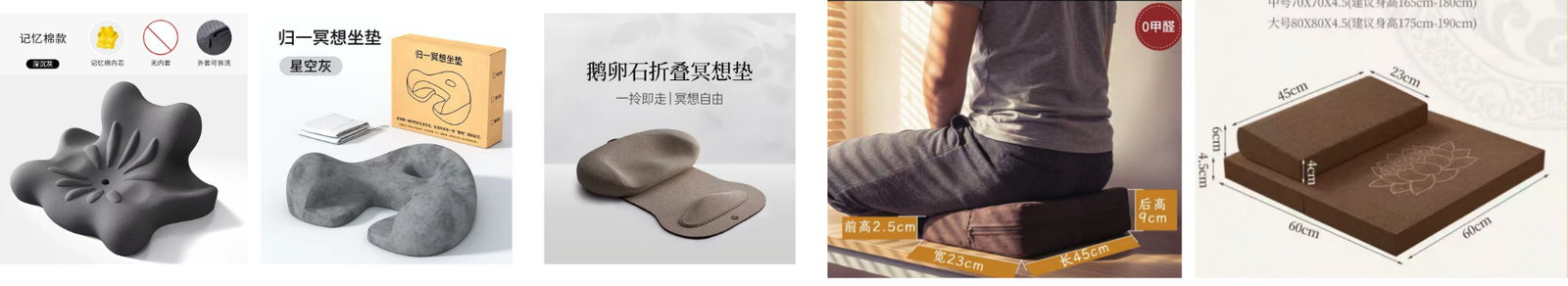
Reference images of meditation cushions and sitting supports.
From these references, I recorded the height, slope, front shape, and how the cushion supports the pelvis. Some cushions were almost flat, while others used a clear height difference.
Interview And Sitting Posture Observation
I asked a professional friend who works with healing practices and body recovery about cushion use, user preference, and user needs. I also observed how people sit when they try to rest or meditate.
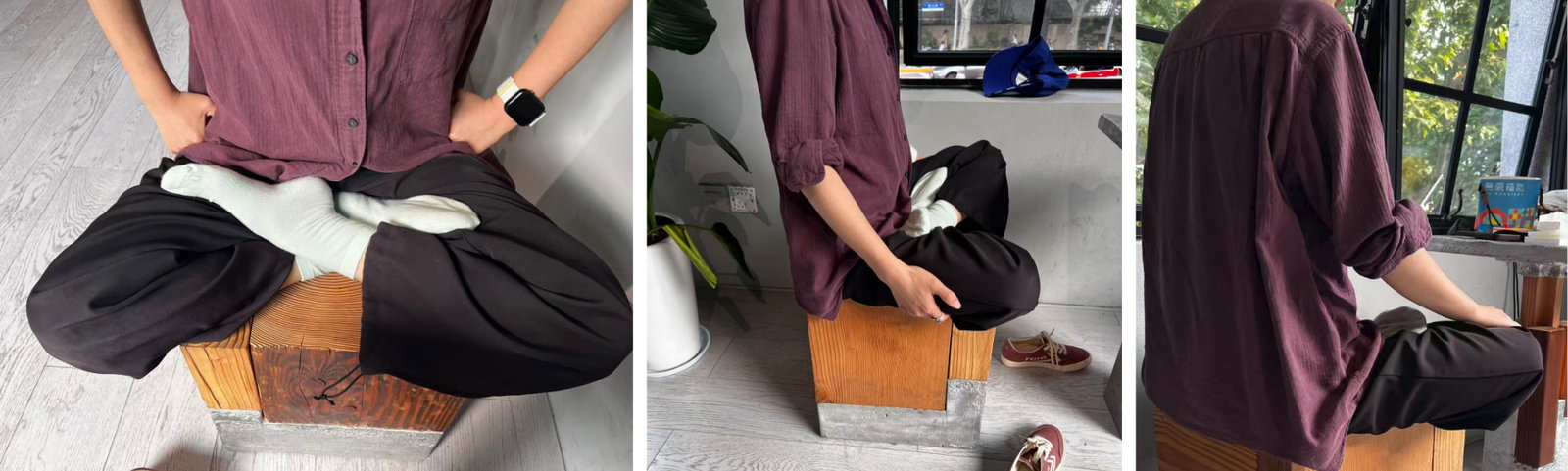
Sitting posture observation and informal user research.
This part helped me move the project from only a glowing object toward a cushion that also considers body posture. The research also showed that not everyone can sit comfortably in a strict cross-legged posture, so the cushion needed to support a more relaxed sitting position.
Sketch Development
After the research, I sketched several directions: a glowing round cushion, a thicker cushion with light around the edge, and a sloped cushion structure with space for lighting and electronics.
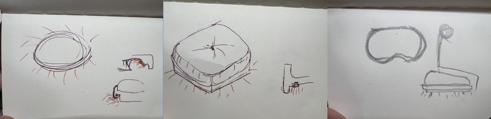
Early sketches showing the transition from a glowing round cushion to a sloped sitting structure.
The main change in this stage was the move from a round glowing shape to a sloped structure. I kept the lighting idea, but the form became more related to sitting and body support.
Fusion Structure Design
I built the final cushion direction in Fusion. The model used a sloped profile, a front opening, space for the LED strip, and internal space for sensors and wiring.
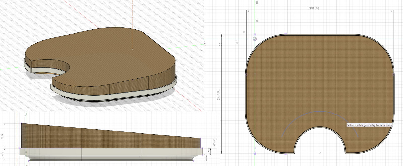
Final cushion structure in Fusion.
The Fusion model helped me check the 30 mm height difference and the relationship between the upper cushion, the wooden base, and the LED route. This model became the reference for the later CNC base and foam cutting.
Hidden LED Groove Design And Test
I tested the housing and diffuser for the hidden COB LED strip. I started from reference research, then modelled and printed small samples before testing them with the real light strip.
Reference Research
I collected LED profile and concealed lighting references.
I looked at linear lighting details, LED channels, and diffuser covers. Because this cushion is much smaller than an interior lighting detail, I needed to scale the idea down and test the proportion again.
Fusion Modelling
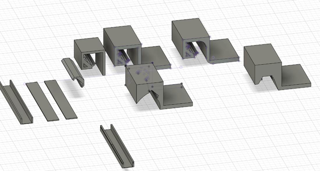
I modelled several LED profile cross-sections in Fusion.
I tried several cross-section versions to compare the LED position, diffuser distance, wall thickness, and whether the shape could be printed.
Dimension Check
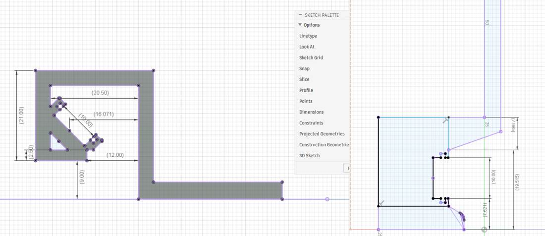
I checked the profile dimensions before printing.
Some dimensions looked possible in the model but were too small or too tight for printing and assembly. I removed those options before printing the sample.
White PETG Printing Test
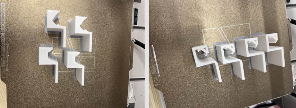
I printed 20 cm white PETG samples for the housing.
I printed a 20 cm test piece instead of the full structure. This saved time and material, and it was enough to check the section, support marks, stiffness, and assembly gap.
Selected Diffuser Combination
I selected the diffuser combination that worked better for the COB LED strip.
After comparing the printed samples, I selected the red-marked combination. It gave more space between the LED and the diffuser and made the light less concentrated.
COB LED Diffusion Test
I tested the printed samples with the real COB LED strip.
The test showed that the selected diffuser softened the COB strip and spread the light better. This result was good enough to continue using this direction in the cushion structure.
Pressure Sensor And 24V LED Interaction Test
I tested the input and output system before putting it into the cushion. The test used an FSR pressure sensor, XIAO ESP32-C3, MOSFET module, and 24V COB LED strip.
Related weekly pages:
Foam And FSR Setup
I placed the FSR under a foam layer to test whether pressure could still be read through soft material.
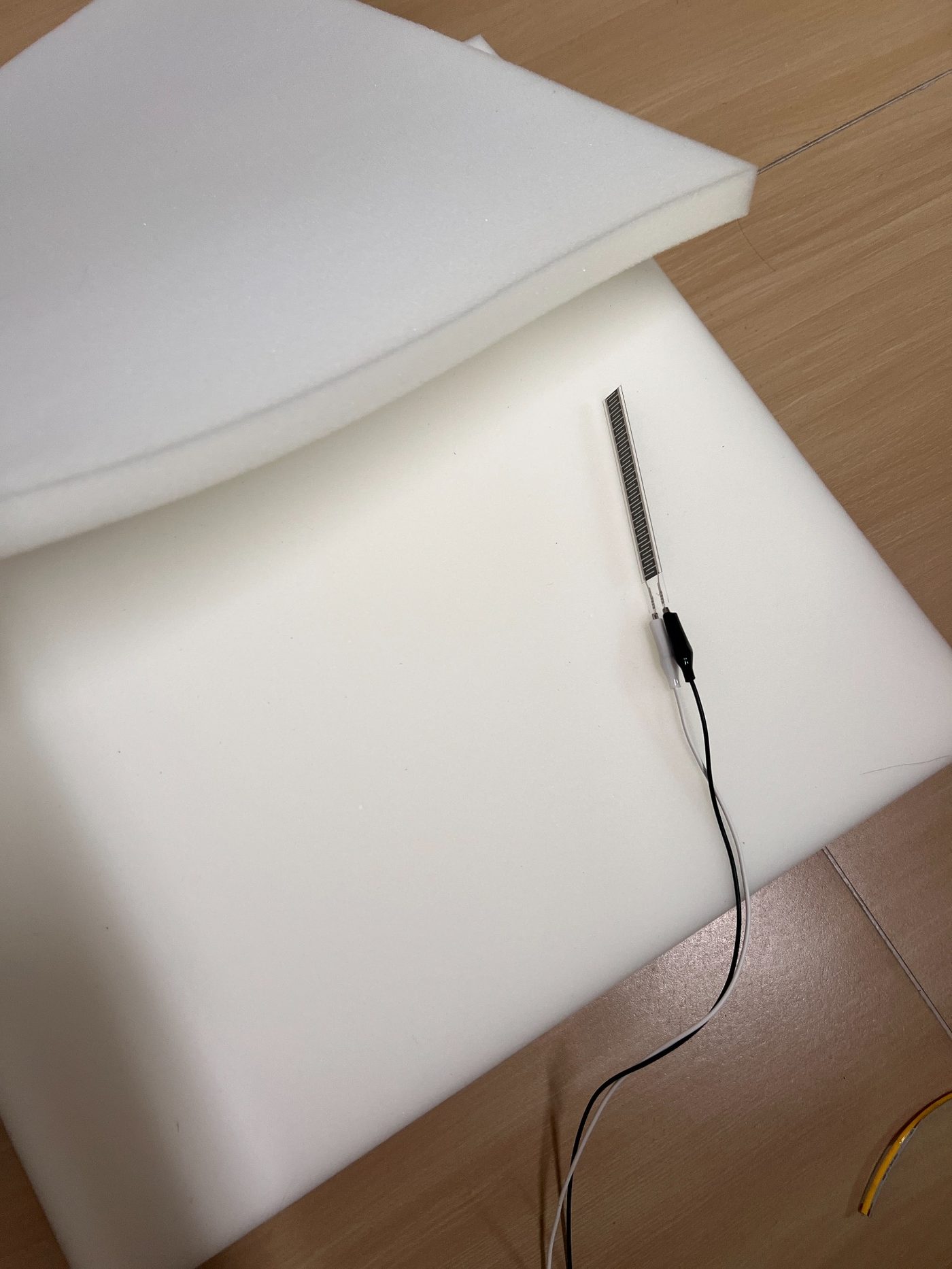
FSR pressure sensor test under foam.
The test showed that the foam could protect the sensor, but it also reduced and softened the pressure response. This meant the threshold and filtering needed to be tuned later.
Circuit And Wiring Test
I connected the FSR to the XIAO analog input and used the XIAO PWM output to control the MOSFET. The MOSFET controlled the 24V COB LED strip.
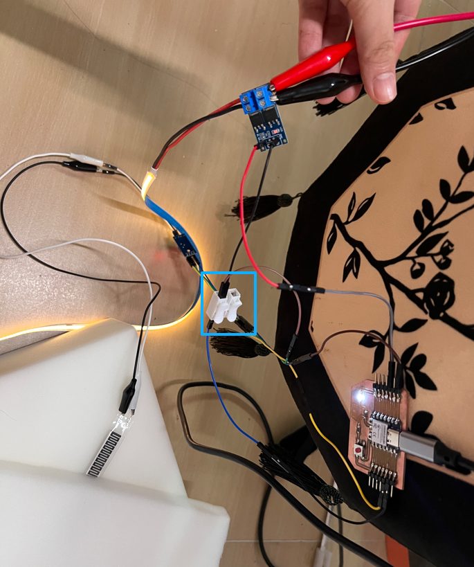
Common ground wiring module used in the pressure-to-light test.
The first test did not work correctly because some wiring points were wrong. I checked the FSR, XIAO, MOSFET, and 24V power path again, then corrected the wiring.
After that, the LED still behaved unstably. The problem was a loose alligator clip in the 24V power path. I tightened the clip and checked the common ground connection again, then the LED strip responded correctly to the pressure input.
Interaction Tuning
After the circuit worked, I tuned the light states: idle glow, fade-in, breathing light, and fade-out. I also tested the pressure threshold, stable pressure timing, and release behavior.
Video test of pressure-controlled breathing light.
The main issue in this stage was flickering from small FSR value changes. I adjusted the pressure threshold, waiting time, and breathing cycle so the light would change more slowly and feel less mechanical.
Dual FSR Trial
After the first MVP test, I planned a dual-FSR layout. The left and right FSRs can be used to check sitting pressure and left-right weight difference.
I also considered using three sensors, but this would add more wiring, more calibration, and more possible failure points. For this prototype, two FSR sensors are enough to test the main interaction.
Manufacturing Model And Electronic Integration Planning
After the Fusion model and interaction tests, I planned how the soft cushion, wooden support, LED base, and electronics would fit together.
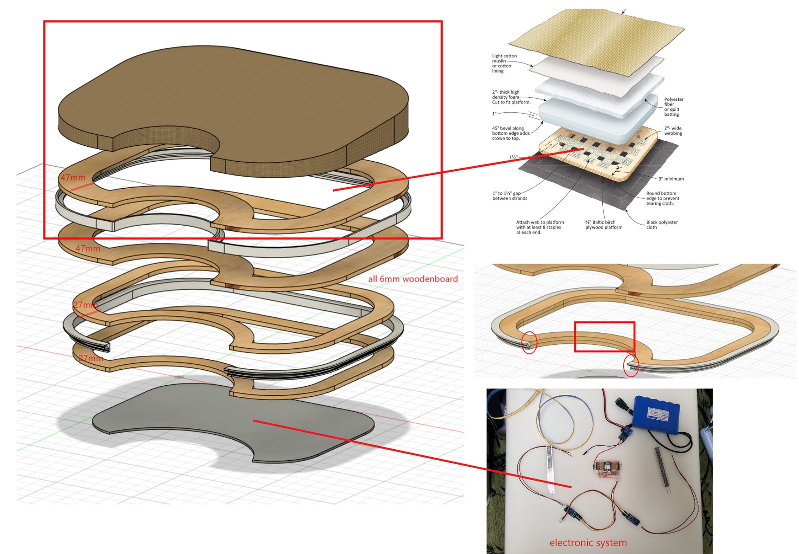
Manufacturing model showing the cushion body, wooden structure, LED base, and electronics area.
Structure Plan
The planned structure includes the upper cushion, wooden layers, base layer, front concave area, and electronic system area.
Electronic Compartment
I planned the electronic compartment near the front concave area. This area can hold the XIAO, MOSFET, 24V power input, common ground connection, FSR connectors, and LED connector.
The main issue here was access. The electronics needed to be hidden, but they also needed to stay reachable for testing and repair.
LED Wiring Plan
COB LED strip will be placed around the base of the cushion, and the wires will be routed toward the electronic compartment.
I planned a shallow groove and protected pass-through area so the LED wire would not be exposed or crushed by the cushion structure.
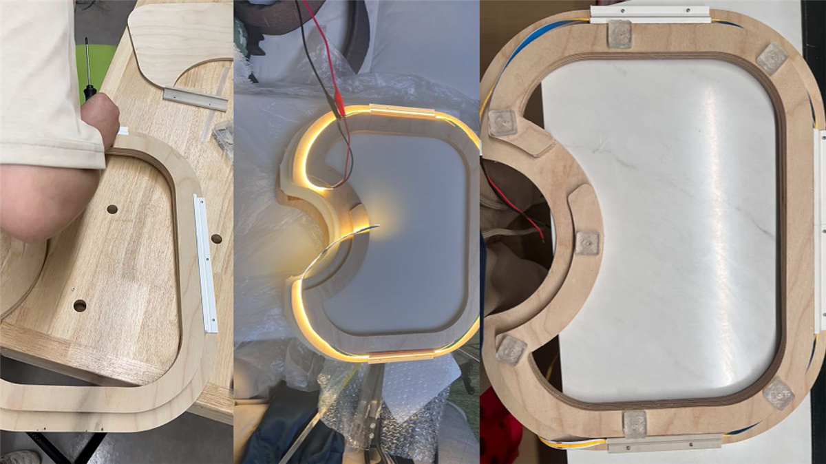
CNC Wooden Base And Cushion Assembly
CNC Bed Problem And Machine Fixing
I first tried to cut the wooden base on May 29. The machine worktable moved, so the vacuum bed could not hold the board firmly and the first cutting failed.
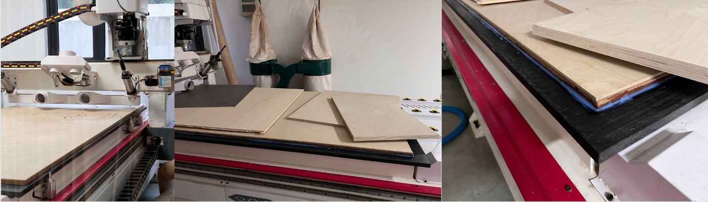
First CNC attempt and machine bed fixing.
After checking the machine with my tutor and the supplier, we used silicone / glass glue to fix the worktable. It needed around 24 hours to dry before the next cutting attempt.
Second CNC Cutting And Recutting
On June 2, I cut the wooden pieces again. Before cutting, we pressed the board flatter with the vacuum system so the material could be held more firmly. Before the second cutting attempt, I went back to Fusion / CAM to check the wooden frame model, cutting paths, and material layout. This step helped me confirm that each wooden layer, inner opening, and front concave area still matched the final cushion structure.
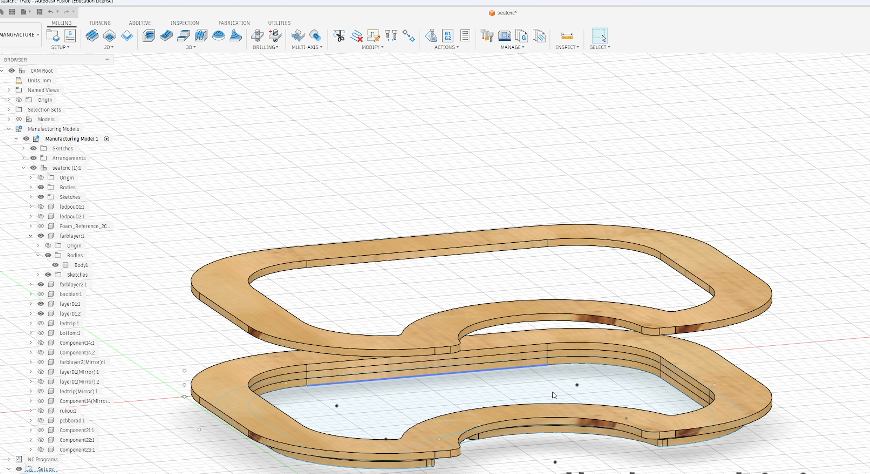
Checking the wooden frame model and cutting path in the CNC software.
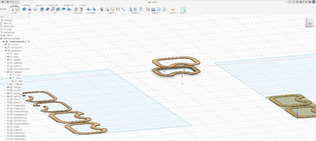
Checking the wooden frame layout and the piece that needed to be recut before the second CNC attempt.
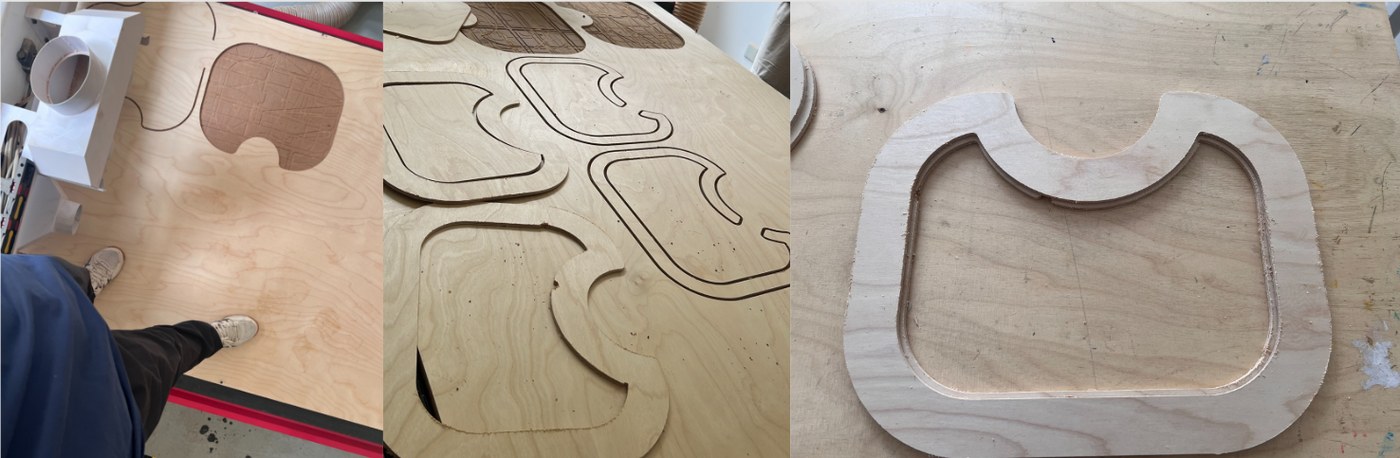
Second CNC cutting and recutting one shifted piece.
This time the cutting worked, but one piece still had a dimensional offset because of slight movement. I recut that piece on the same day and got the complete set of wooden parts.
Edge Sanding
After CNC cutting, I sanded the wooden edges.
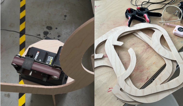
Sanding the CNC-cut wooden pieces.
This step was straightforward. It made the pieces smoother and easier to glue.
Gluing And Clamping The Wooden Frame
I glued the wooden layers and used clamps to hold the curved frame while the glue dried.
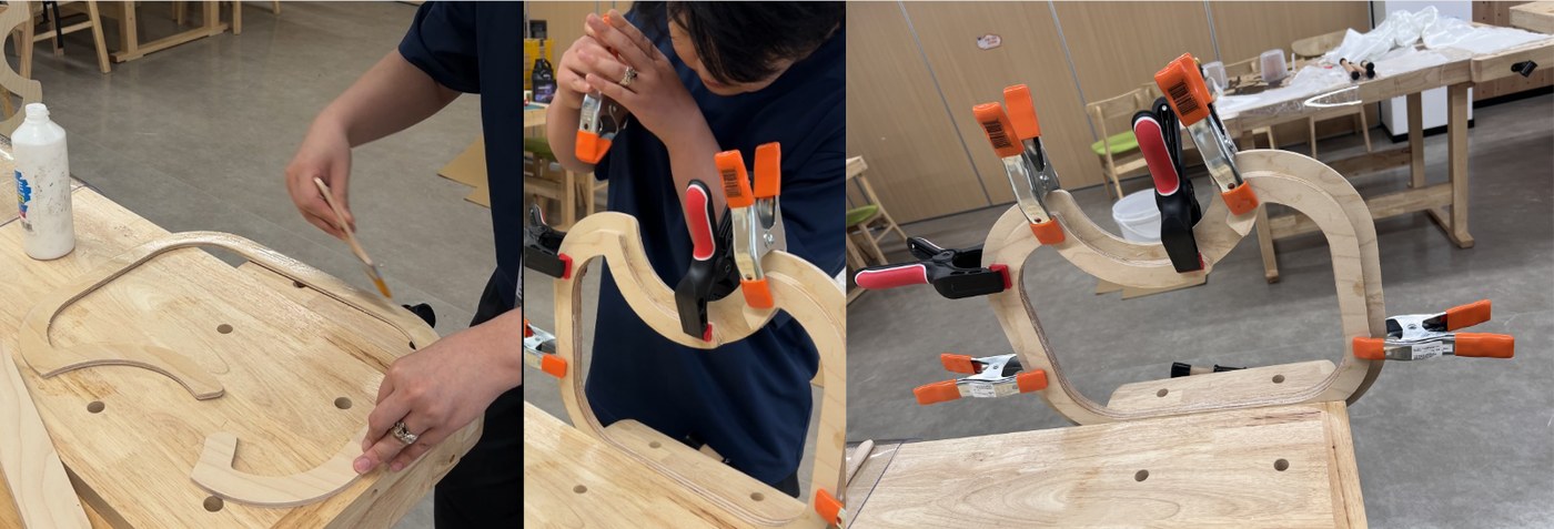
Gluing and clamping the wooden frame.
The main thing to control was movement during drying, so I used several clamps to keep the curved frame in position.
Elastic Webbing Support
I tested elastic webbing on the wooden frame. I first tested the staple gun on scrap wood.
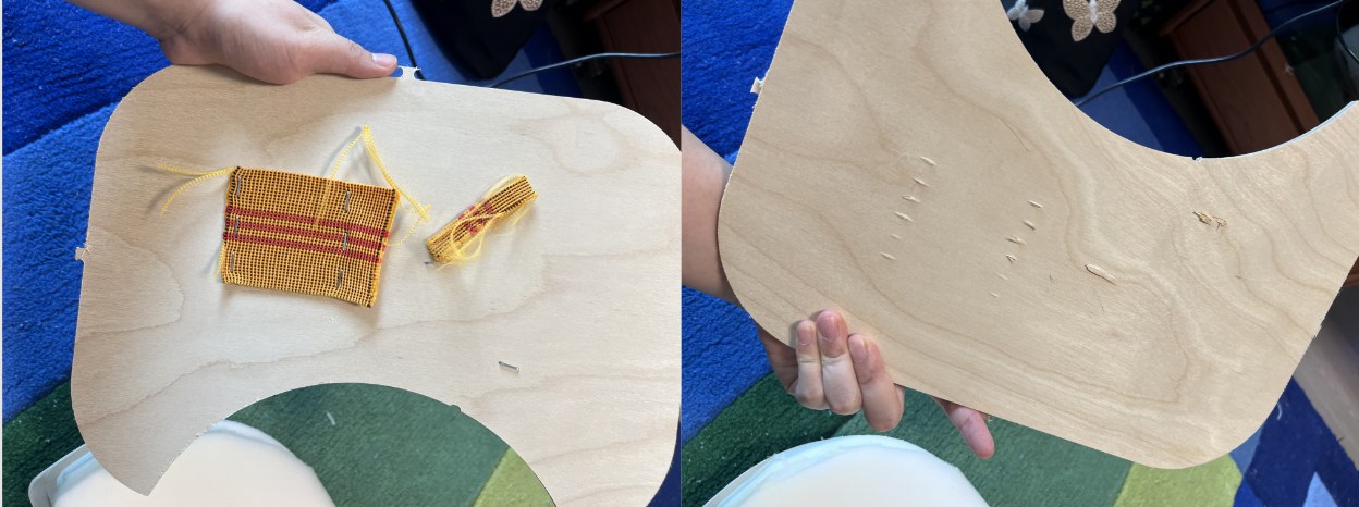
Staple gun test before fixing the webbing.
The staple gun could fix the elastic band, but it could also shoot through the material if the pressure and position were not controlled. When fixing the real webbing, one person pulled the elastic band and another fixed it with the staple gun.
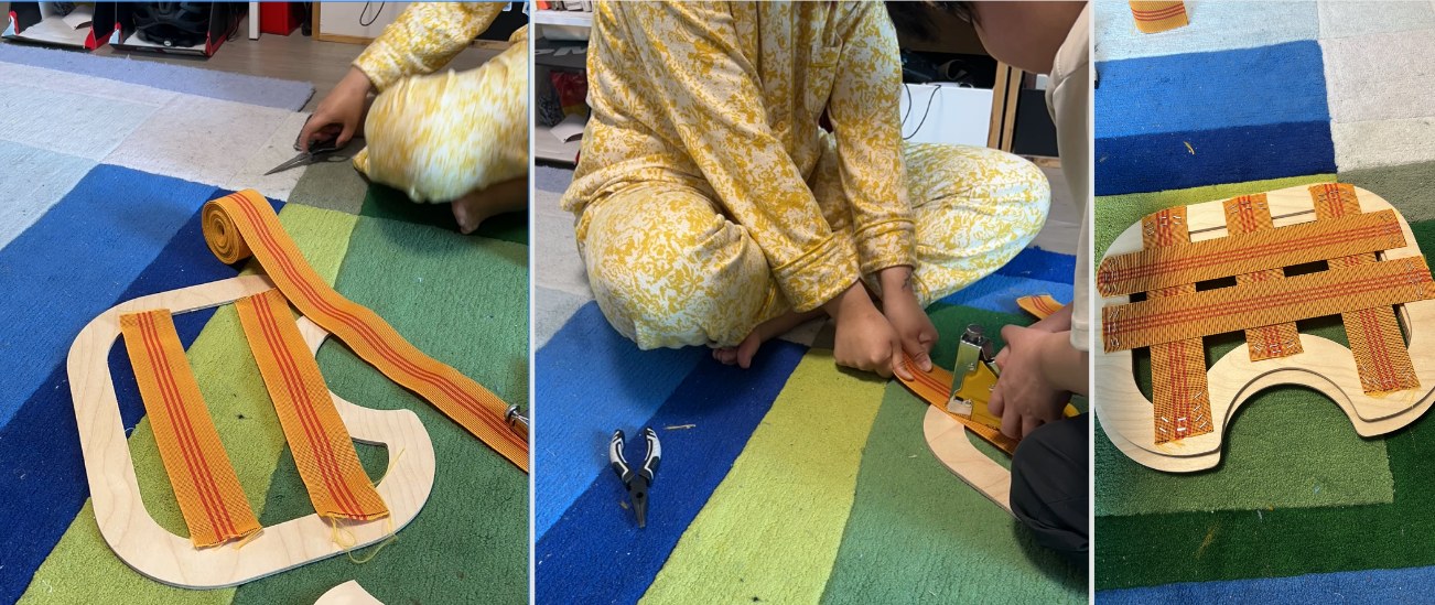
Elastic webbing support test on the wooden frame.
After the webbing was installed, we sat on it to test the support. The result was usable and gave the seat a softer support surface.
Foam Cutting
I cut the foam body with a foam knife and hot wire cutter.
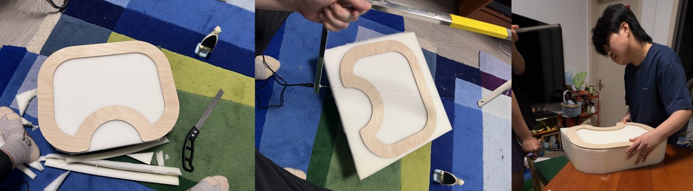
Foam cutting tools.
The hot wire could cut the foam, but it produced smoke, so ventilation was needed. The angled surface was difficult to cut cleanly by hand.
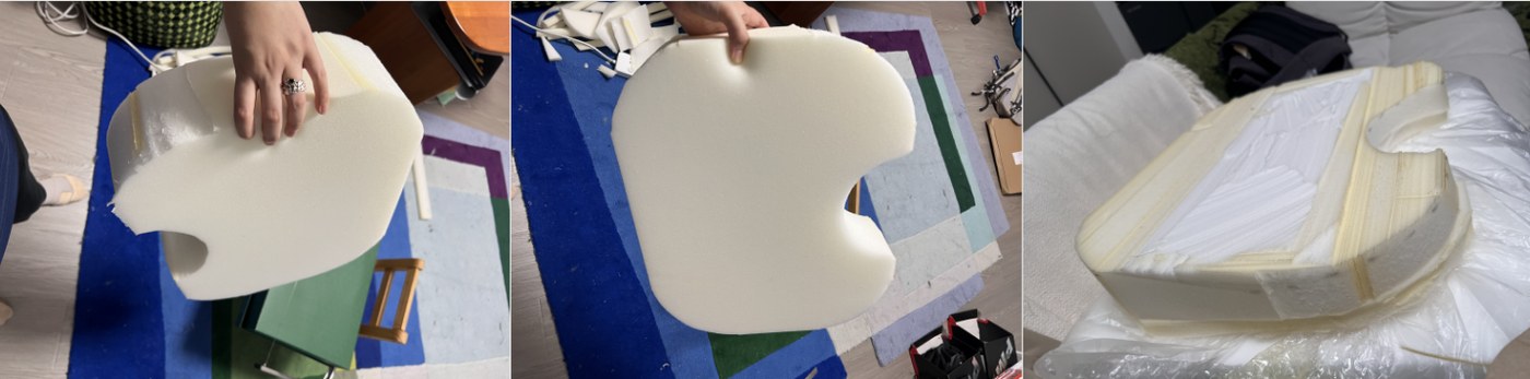
Foam body after cutting.
The result was usable, but the slope and surface still needed improvement.
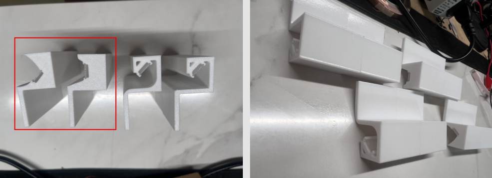
LED Strip Support Fitting
I tested the printed LED strip support with the real wooden board and checked the fitting deviation.
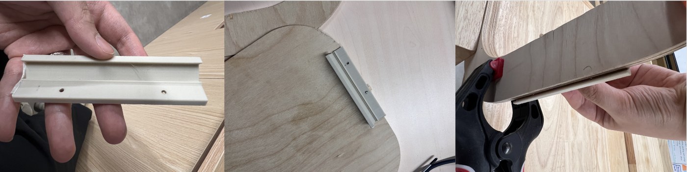
LED strip support fitting test.
The first support part did not fit accurately enough. I measured the deviation and used it as the reference for the next printed version.
LED Holder And Bottom Light Route
After adjusting the LED holder dimensions and checking that the parts fit the wooden frame, I started installing the bottom LED strip. The holder needed to follow the bottom edge of the cushion without affecting how the cushion sits on the floor or blocking the light output.
I first prepared the M2.5 screws, screwdriver, pencil, pre-drilling tool, LED holders, and transparent self-adhesive feet. The transparent feet were purchased parts, so they were easy to use and their height was consistent.
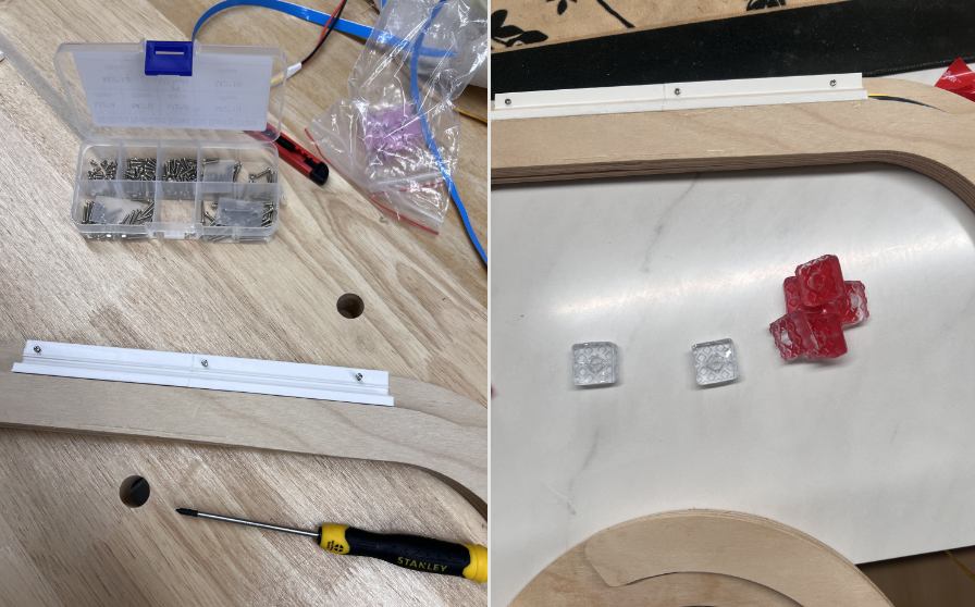
Tools and materials for installing the LED holder, including screws, screwdriver, LED holder, and transparent self-adhesive feet.
For the LED holder installation, I placed the holder on the wooden frame and aligned it with the bottom edge and the LED route. Then I used a pencil through the holes to mark the screw positions. After that, I pre-drilled the holes and manually screwed in the M2.5 screws. This was more controlled than driving the screws directly into the wood, and it reduced the risk of cracking or shifting the position.
Fixing the LED holder with M2.5 screws and testing whether the warm COB LED could come out from the bottom edge.
I also tested the end holders and small module holders. The end pieces were not load-bearing, so some of them were temporarily fixed with glue to check the cable exit and LED end protection.
LED end holder, module holders, and temporary glue fixing test.
I also added transparent self-adhesive feet under the base. These were purchased parts, so they could be applied directly and the height stayed consistent. They raise the bottom of the cushion about 9 mm from the floor, which prevents direct rubbing and leaves a small gap for the bottom light and wiring.
FSR Soldering And Wire Extension
After confirming the left and right FSR positions, I started preparing the FSR wires. The original wires were not long enough to route from the two sensor positions to the electronics compartment, so I bought extra wire and soldered extensions.
After soldering, I protected the connection points with heat-shrink tubing. This prevented exposed solder joints from being pulled or shorted inside the cushion. The two FSR sensors were positioned on the left and right sides, and the wires were routed along the inner edge toward the electronics compartment.
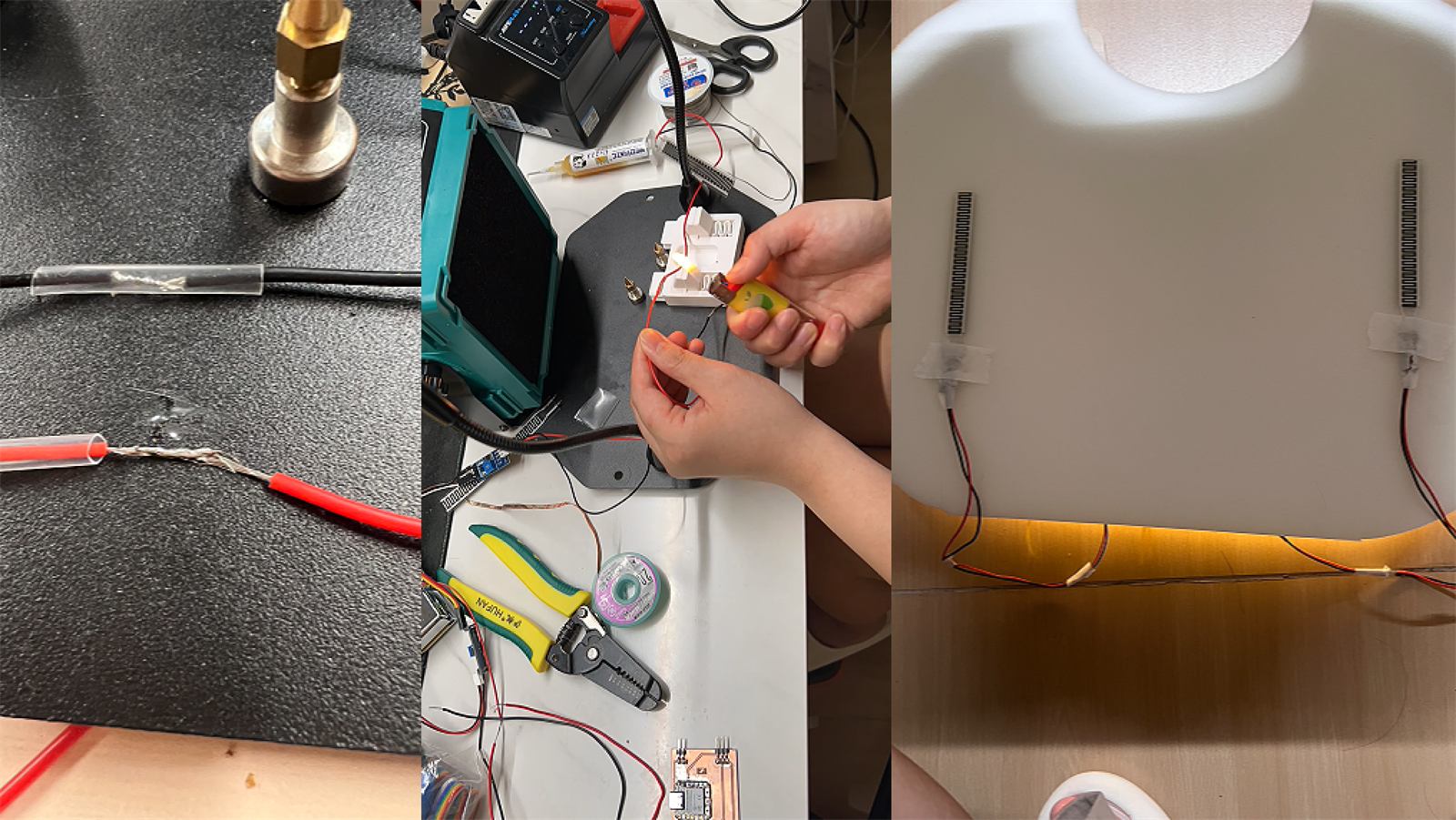
FSR wire extension, heat-shrink protection, and left/right sensor positioning.
Inside the cushion, I temporarily grouped the wires with masking tape for easier management. This was not the final fixing method, but it helped during prototype testing because I could keep the wiring organized and check whether any wire was pinched when closing the structure.
I also checked the final relationship between the foam layers, FSR sensors, lower support foam, elastic webbing, wooden frame, LED route, electronics compartment, and transparent feet.
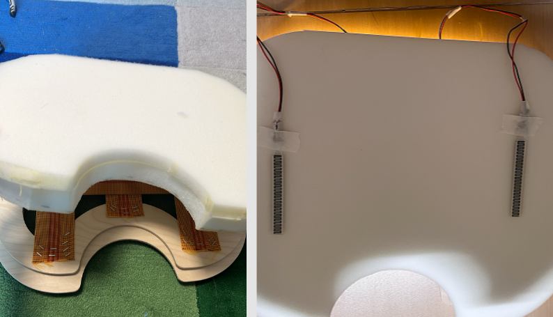
Final foam and FSR stack. From top to bottom: fabric cover, upper foam cushion, FSR pressure sensors, lower 60D support foam, elastic webbing support, wooden frame, LED route, electronics compartment, and transparent self-adhesive feet.
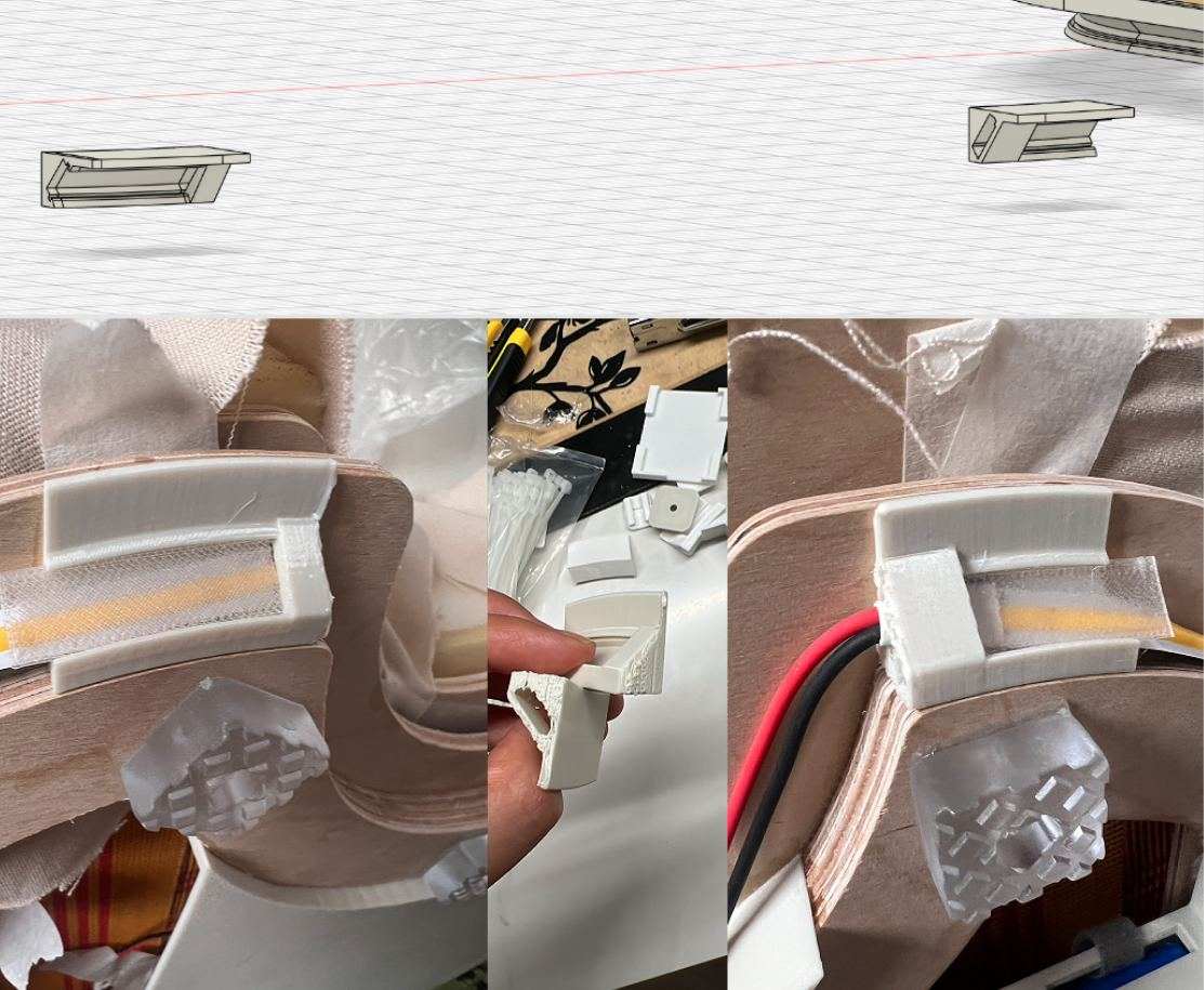
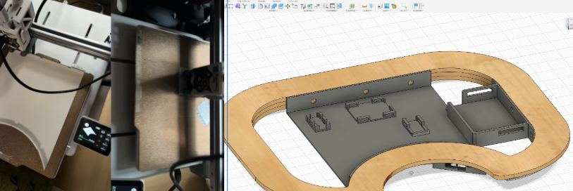
Electronics Compartment
After that, I designed the electronics compartment. This was not only about making a box. I first needed to check whether the PCB, MOSFET, sensor boards, battery, and wires could actually fit inside the wooden frame.
I measured the PCB, sensor modules, MOSFET module, and available internal space with calipers. The first and third images show the measurement process. I placed the real electronic modules near the wooden frame and recorded the board width, height, cable exits, and the spacing needed between modules.
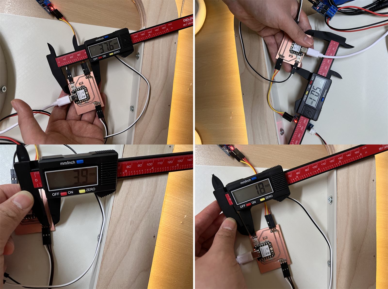
Measuring the PCB and internal wooden-frame space for the electronics holder dimensions.
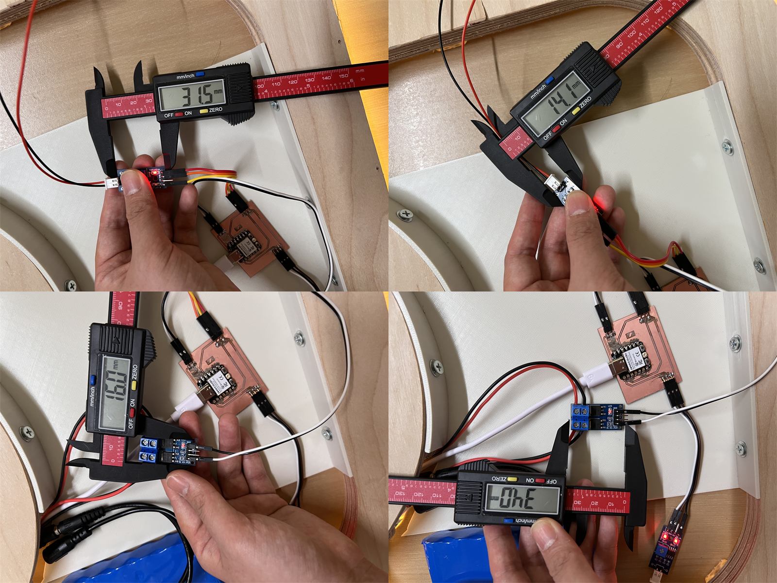
Measuring the MOSFET, sensor modules, and wiring space.
After measuring, I modelled the electronics holder in Fusion. The second image shows the local holder dimensions. I used these dimensions to define the clips, edges, module seats, and screw fixing positions.
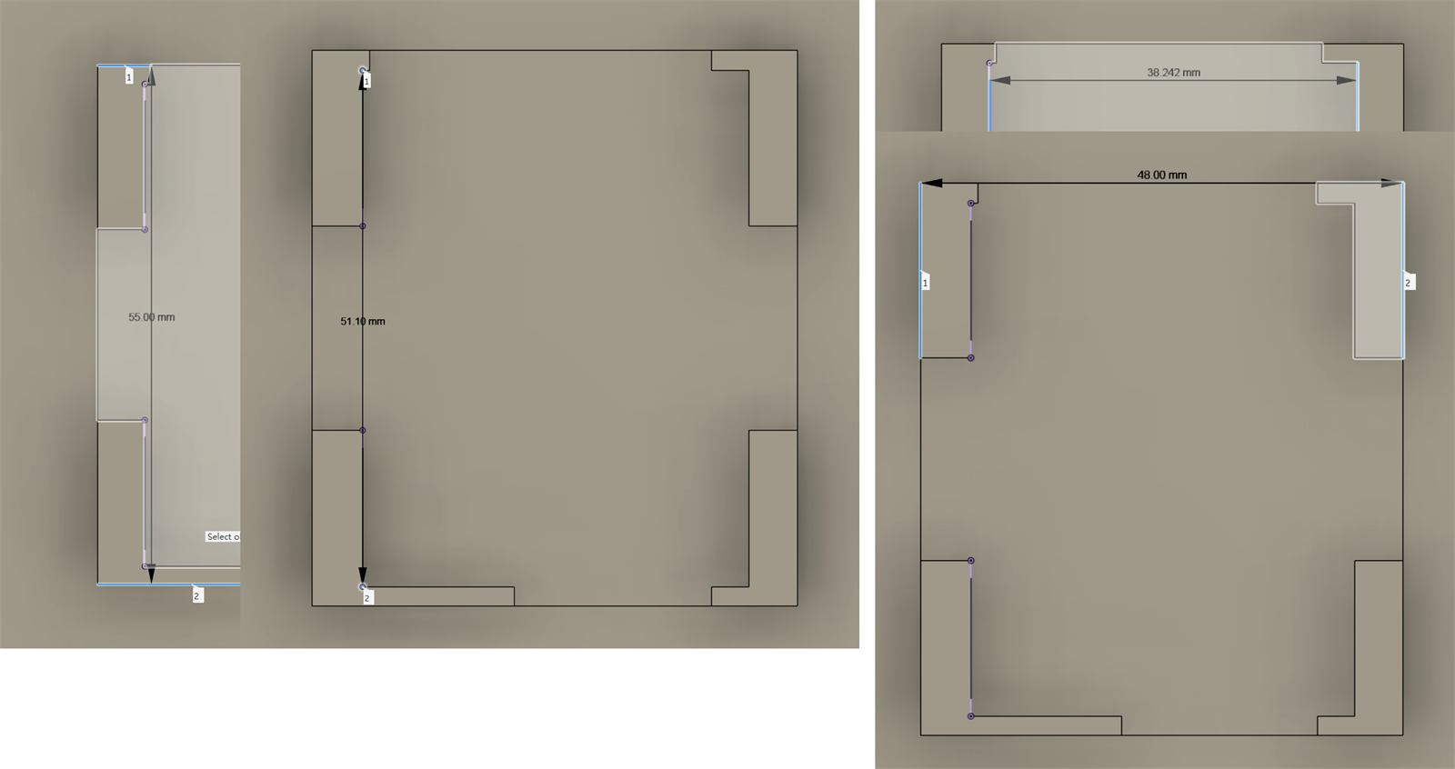
Local modelling dimensions for the electronics holder.
Then I placed the electronics holder back into the full cushion model. The fourth image shows the overall model. It helped me check the relative positions of the PCB, MOSFET, sensor modules, and battery compartment inside the wooden frame, and whether they conflicted with the LED route or frame edge.
Overall electronics holder model and print test.
For installation, I left holes in the holder and frame first. I did not drive the self-tapping screws all the way in at once. I first turned each screw by hand so it entered the material slightly and confirmed the direction, then used an automatic screwdriver to finish tightening it. This reduced slipping and helped avoid cracking the printed part or the wooden board.
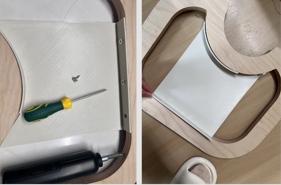
Fixing the electronics holder with self-tapping screws after reserving the hole positions.
The sixth image shows the first positioning idea. I placed the PCB, MOSFET, sensor modules, battery, and wires inside the wooden frame to check the rough location of each module, cable route, and access space for later repair.
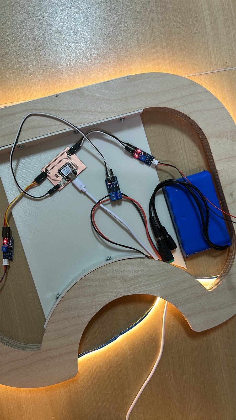
Initial positioning of the electronic modules inside the wooden frame.
Finally, I placed the battery, PCB, MOSFET, and sensor modules into the designed positions. The goal at this stage was to stop the electronics from moving inside the cushion while still leaving space to open and inspect the prototype.
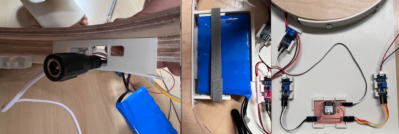
Electronics compartment fixing and positioning. The PCB, MOSFET modules, sensor conversion boards, battery compartment, and wires were arranged before closing the structure.
Some small 3D printed holders were not suitable for more screw fixing, so I used a dedicated glue for 3D models. This fixed the small modules in their planned positions without adding too many screws and holes.
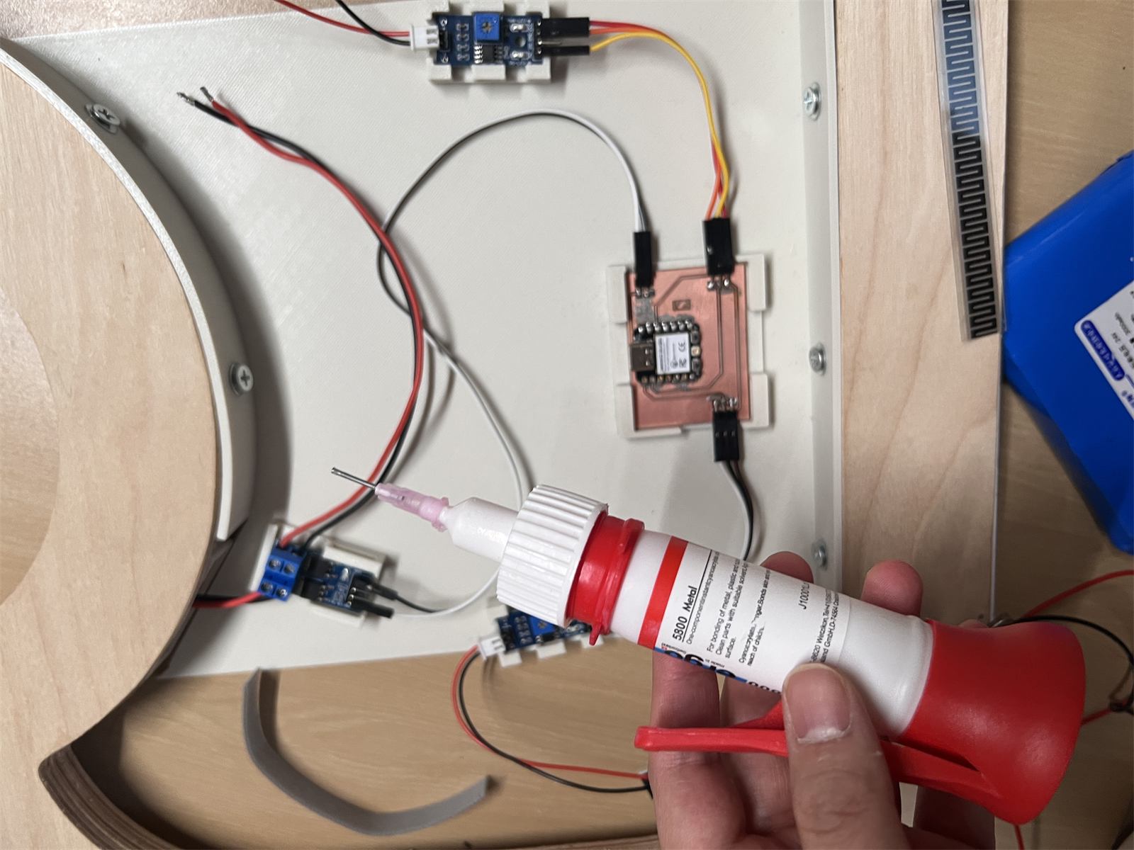
Using dedicated 3D model glue to fix small electronics holders.
The key issue was to avoid crushing the wires. During testing, I repeatedly opened and closed the structure to check whether connectors became loose or wires were pinched.
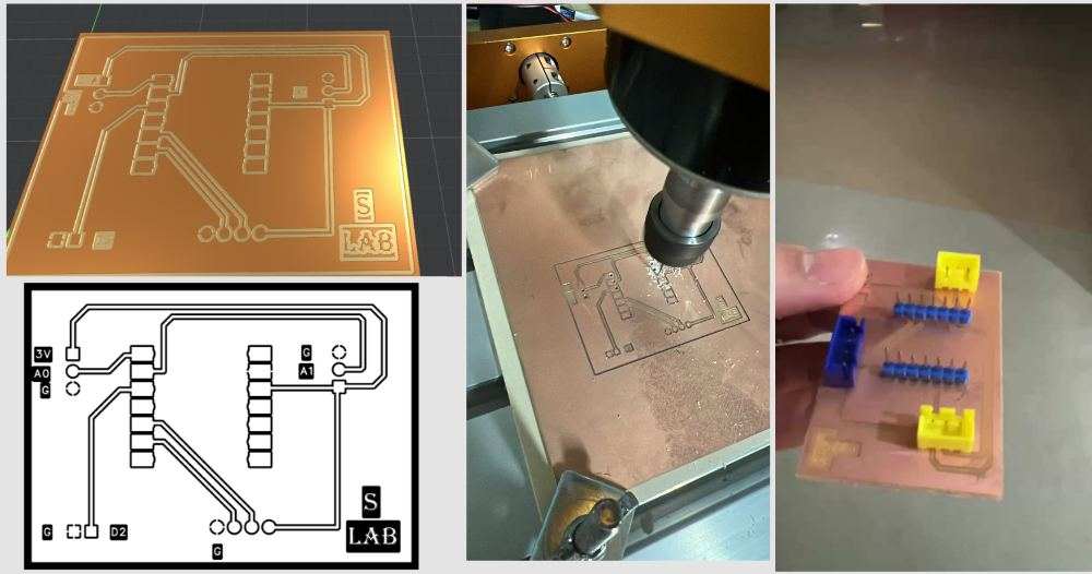
LED Diffuser Strip And First PCB Test Board
I printed a more accurate LED diffuser strip and also made a first PCB test board to check milling, scale, trace size, and connector placement.
For the PCB milling process, I referenced Yaroslav (Yaro) Artsishevskiy''s Week 08 Electronics Production page. I bought the 3018 Pro Max after his recommendation, and I followed his steps for the basic operation, machine setup, and PCB milling workflow.
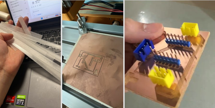
LED diffuser strip and first PCB test board.
This PCB was not the final board. It was a test board for checking the physical milling and connector layout before making the final carrier board.
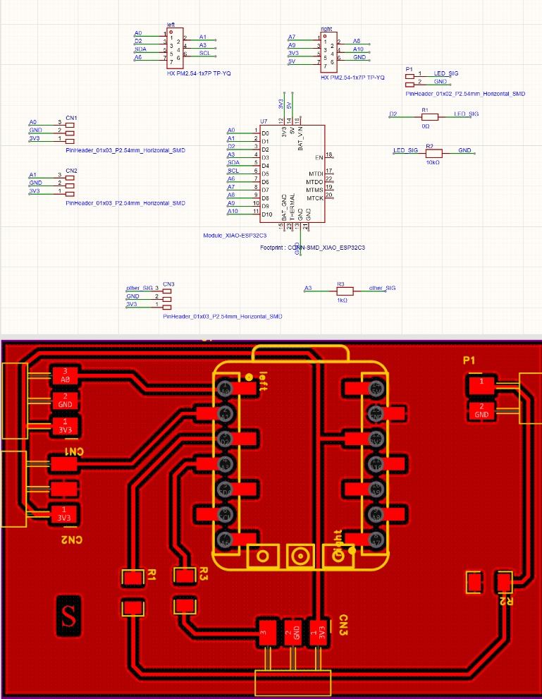
Before making the physical board, I listed the interfaces I needed to bring out. At this stage, I did not need to show a complex interface diagram. A table was clearer for confirming which signals needed to come out from the XIAO ESP32-C3.
| Interface | Pins | Use |
|---|---|---|
| Left FSR | 3V3, A0, GND | Left pressure sensor input |
| Right FSR | 3V3, A1, GND | Right pressure sensor input |
| LED / MOSFET control | D2, GND | Controls the MOSFET, then the 24V COB LED |
| Optional I2C / test interface | 3V3, SDA, SCL, GND | Reserved for OLED or later testing |
After that, I drew the schematic and layout. This board was planned for PCB milling, and it was mainly used to organize the low-voltage signal connections inside the cushion.
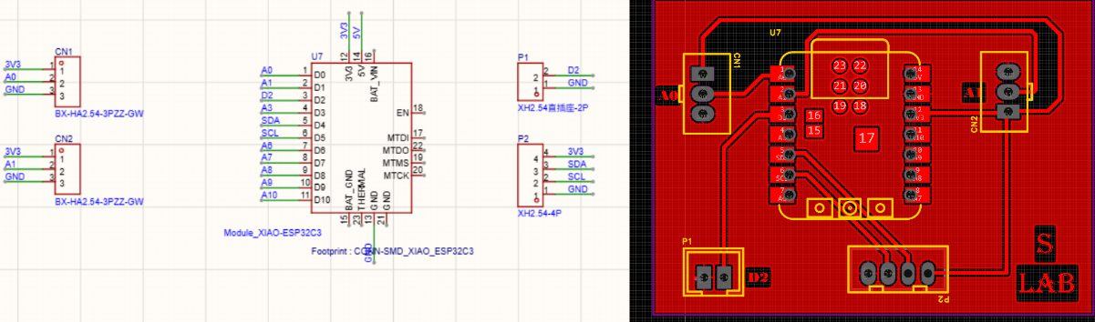 Complete PCB schematic and layout overview. I used this version to check the signal routes before milling and soldering.
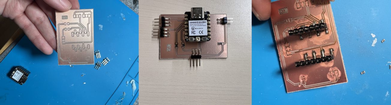
My first physical version used terminal connectors. I thought this would make the wires easier to plug in and remove.
First PCB idea with terminal connectors. This version helped me start organizing the left and right FSR connections, but it was difficult to solder cleanly.
3018 machine running video, used as additional evidence for the PCB making process.
After trying it, I found several problems. The terminal connectors were hard for me to solder, and I also soldered some parts on the wrong side during the early test. The terminals were also too tall for the electronics compartment, because the inside of the cushion has very limited height. Because of this, I changed the connector strategy to lower SMD pin headers.
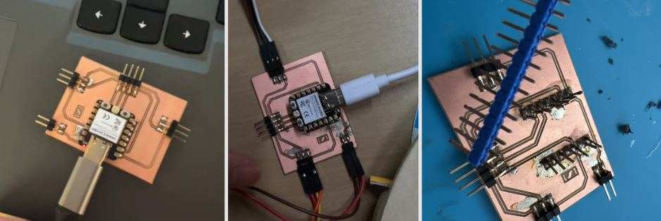
The SMD pin-header version reduced the connector height, but the contact was still not always stable.
This video records the unstable PCB contact problem. The board could work, but the connection method still needed improvement.
At this stage, I do not want to describe this as the final PCB. It is still a prototype. The test helped me understand the size, height, and wiring route, but I still plan to buy proper female headers and make a cleaner next PCB version.
Safety Notes
During cutting, sanding, hot wire cutting, and staple gun testing, I found that I need better protection.
I scratched my finger when moving a steel plate, and I also burned myself when using the hot wire cutter. For the next steps, I need gloves, ventilation, and more careful tool handling.
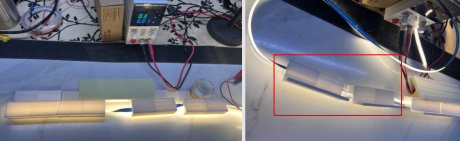
Fabric Covering And Closed Test
Closed Cushion Test
Before the fabric cover was finished, I recorded a closed-cushion test video. This test checked whether the warm bottom light could still come out from the edge, whether any wires were being pressed, and whether the structure stayed stable during a short sitting test.
Closed-cushion test before the final fabric covering. I placed this video in the closed test section because it records the earlier test state.
Fabric Covering
At the end, I worked on the outer fabric covering. The fabric I originally bought was not wide enough to cover the whole cushion, so I later found an old piece of clothing and used it as a temporary outer cover.
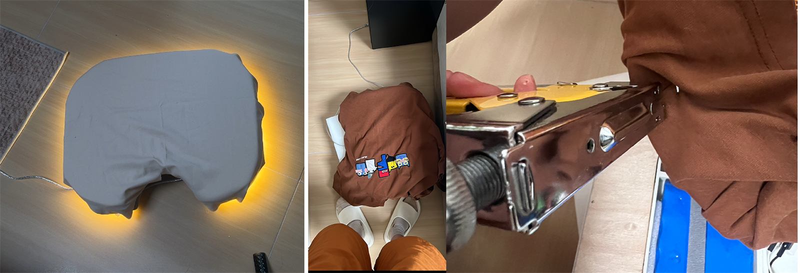
Old-clothes fabric covering, bottom light effect, and staple fixing process.
I pulled the fabric around the edge and underside of the cushion, then fixed it with staples. This is not a production-level sewing solution, but it was useful for the prototype because it let me finish the outer appearance quickly and continue checking whether the bottom light could still glow through the edge.
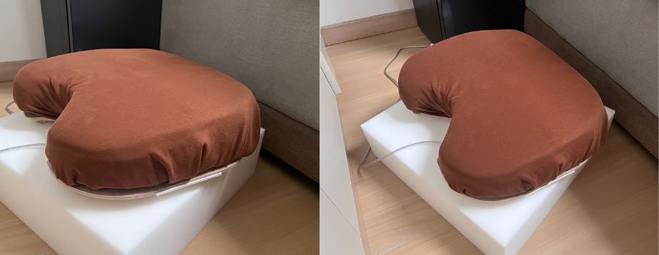
Final cushion after wrapping the fabric cover. The electronics and wooden structure are hidden inside, while the object reads visually as a soft cushion.
Direct-Solder PCB Version And V2 Plan
Because the previous pin-header and jumper-wire connections had unstable contact, I first tested the board inside the wooden frame and confirmed that it could work in that position. After that, I made an intermediate version where the connections were soldered directly onto the PCB. This reduced looseness, but it created another problem: the XIAO was fixed on the board, so it was difficult to replace if it burned out or needed to be changed.
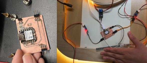
After the previous contact issue, I tested this board inside the wooden frame. It could work in the installation position, but the connection method still needed improvement.
During longer testing, I did burn one XIAO, so I started planning a V2 PCB. The main goal of V2 is to mount the XIAO with female headers, so that the microcontroller can be replaced instead of throwing away the whole board.
For V2, I planned to use female headers so the XIAO is not permanently soldered to the board.
V2 PCB schematic and layout. I included the left and right FSR inputs, LED control, and extra expansion interfaces.
I also kept some possible expansion directions in V2. One option is to connect an ultrasonic atomizer module, so the cushion could later include a subtle scent cue. Another option is a small vibration module. I only need a very small vibration reminder, not a strong haptic output.
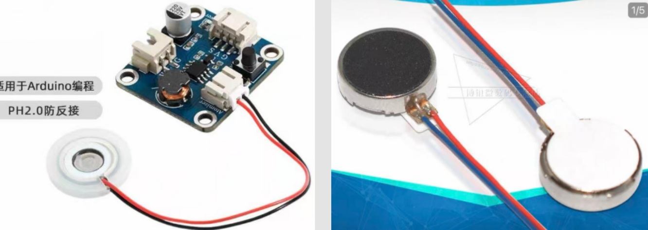
The third reference shows an atomizer module and small phone-style vibration modules. For now, these are possible V2 extensions.
V2 PCB Soldered Board And Function Test
After finishing the V2 PCB design, I continued making and soldering the new board. Different from the previous intermediate version where the XIAO was soldered directly onto the board, this version uses female headers so the XIAO can be plugged in and removed. If the microcontroller burns out during later testing, or if I need to change it, I do not need to throw away the whole PCB.
V2 PCB after soldering. This version keeps the XIAO replaceable while still connecting the left and right FSR sensors, LED control, and expansion interfaces.
After soldering, I tested the basic functions of the board. The test was successful: the board could read the pressure sensor values and control the light output. This confirmed that the V2 PCB direction was working.
V2 PCB soldered version test. The board worked after soldering and could be used for the next interaction tests.
Web Debug Interface
After the PCB test worked, I continued improving the web debugging interface. This web page is simpler than the one I made during the Network and Communications week, but it is more suitable for this final project.
The interface allows me to directly adjust the lighting effect and see the left and right pressure values. From the two FSR readings, I can also understand whether the body is leaning more to one side. This makes the sitting state more visible to the user, and it also helps me tune the lighting parameters for a more comfortable resting experience.
Web debug interface test. I used this page to observe the pressure values, body leaning direction, and real-time lighting changes while interacting with the cushion.
Lighting feedback parameter test. I used the web interface to adjust the light response and try parameters that felt more comfortable for resting.
Atomizer Module Test
Later, I changed to another atomizer module and tested it as a possible V2 extension. This module is small enough to fit into a later version of the cushion structure. It could allow the cushion to give a subtle scent cue in addition to the lighting feedback.
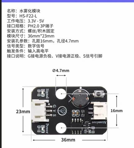
| Item | Specification |
|---|---|
| Name | Water atomizer module |
| Model | HS-F22-L |
| Working voltage | 3.3V - 5V |
| Connector | PH2.0 3-pin |
| Installation | Screw / standoff fixing |
| Module size | 36 mm x 23 mm |
| Mounting hole distance | 16 mm |
| Mounting hole diameter | 4.7 mm |
| Signal type | Digital signal |
| Trigger condition | Input high level |
| Interface | G = power negative, V = power positive, S = signal pin |
I quickly tested the atomizer together with the pressure sensor. When sitting pressure was detected, the atomizer turned on. When the pressure disappeared after the user left the cushion, the atomizer turned off. I also added easing logic so the transition felt softer instead of switching suddenly.
Pressure-linked atomizer test. When the cushion sensed sitting pressure, the atomizer turned on; when the pressure disappeared, it turned off with a smoother transition.
This test showed that V2 can continue developing toward smell feedback. It does not need to be a strong function; it can be a small sensory cue that works together with the light to support resting.
Source Files
3D printing models:
PCB files:
Arduino code:
Web interface:
The online Fusion model is here: