10 Output devices
Assignment
- Group assignment:
- Measure the power consumption of an output device.
- Document your work on the group work page and reflect on your individual page what you learned.
- Individual assignment:
- Add an output device to a microcontroller board you've designed and program it to do something.
Overview
In this assignment, my primary goal was to integrate output devices into a microcontroller board I designed. However, during the testing phase, I encountered some technical issues with my custom PCB that are currently being debugged. To ensure a deep understanding of the output logic and to verify my code's functionality, I decided to use the Seeed Studio XIAO ESP32C3 as a prototyping platform. This allows me to master the programming of the RGB LED, Servo, and OLED display while I continue to troubleshoot my custom hardware.
Group Assignment
Link:
https://fabacademy.org/2026/labs/formshop/students/zequan-lin/weekly/10%20Output%20devices/
What I learned: From Zequan Lin's group documentation and my own power-supply test, I learned that an output device should be treated as a real electrical load, not only as something controlled by code. Using a bench power supply made this clearer because I could set a safe voltage and current limit, observe how much current the output device used in different states, and calculate the power consumption with P = V x I. This helped me understand why some output devices need external power, why the microcontroller should not be overloaded, and why stable voltage, current capacity, and common ground are important when connecting an output device to a board.
Related Web Control Test
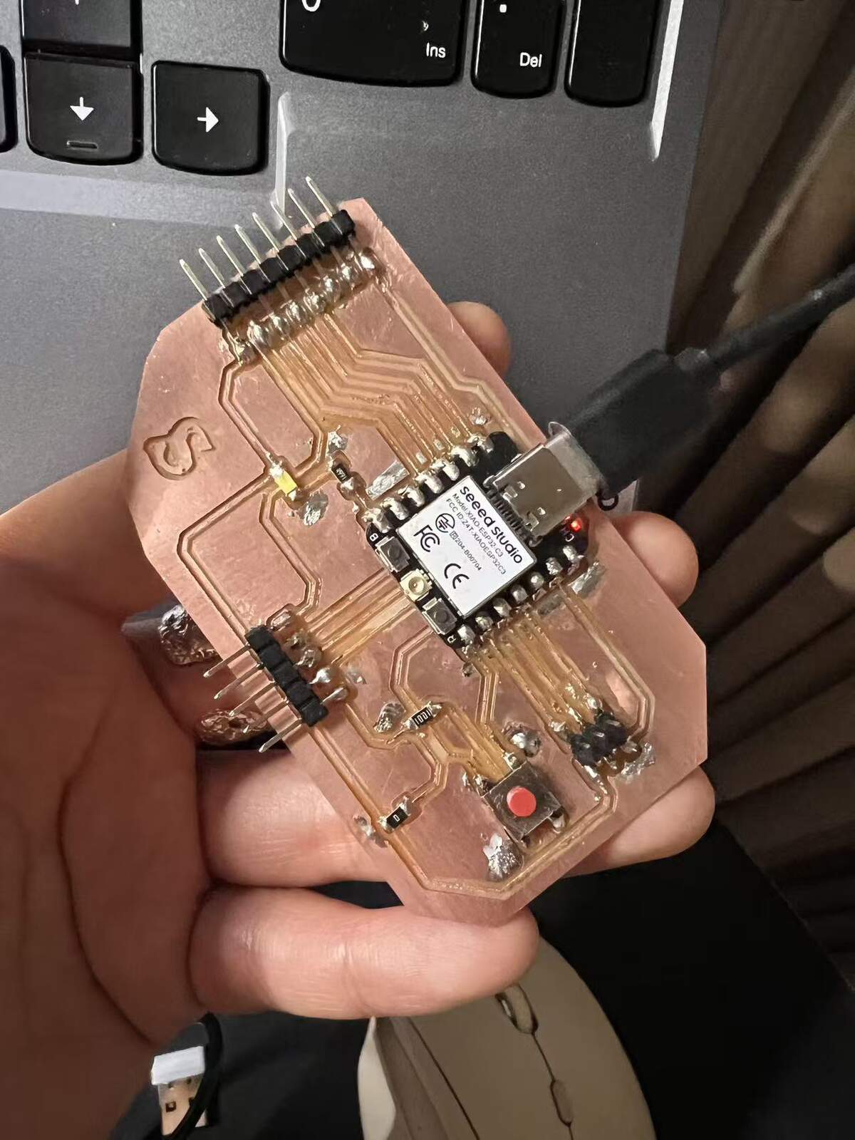
I have already completed the web-based control test with my custom board and a programmable LED strip. The board can receive control from the web interface and change the LED behavior. This confirms that the basic workflow between the custom board, LED output, and web interface works.
The detailed web control test is documented here:
Web Control / Network Connection Test
This Week 10 page focuses on the output device side. The later system integration page explains the network connection and web interface in more detail.
Custom Board + Programmable LED Strip Output Test
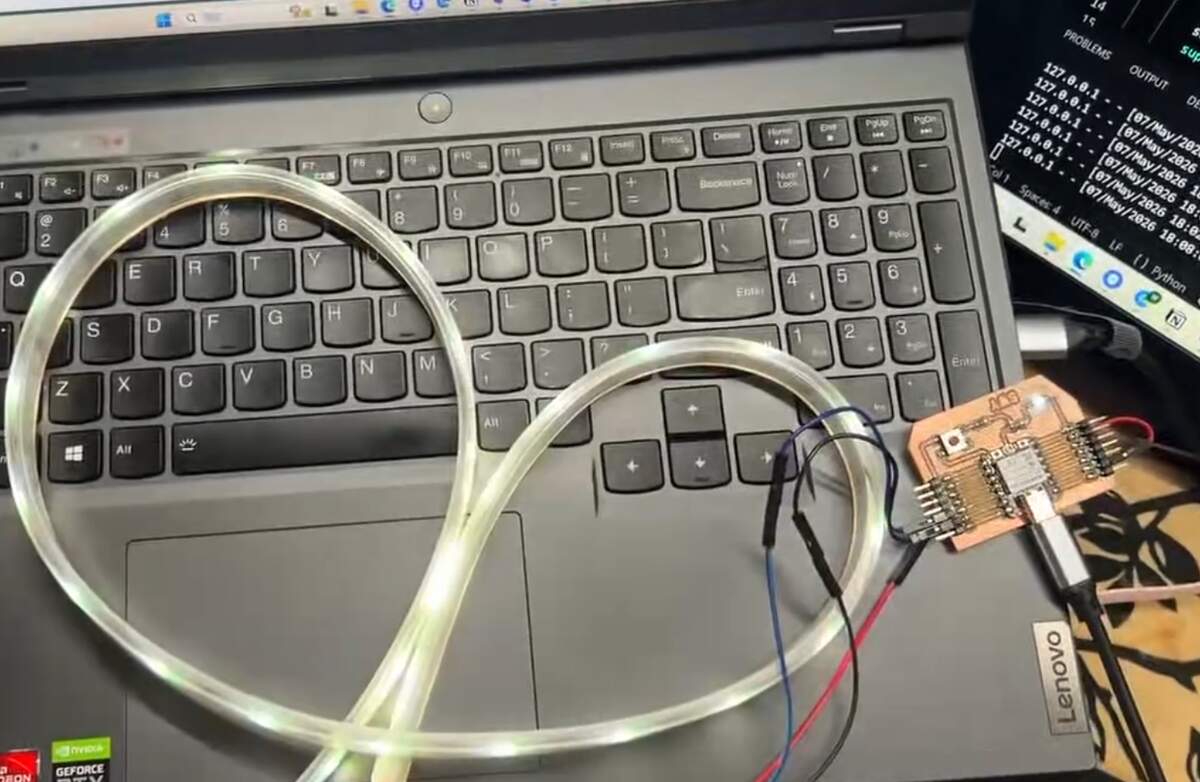
My custom board still had bugs this week, so I used the XIAO ESP32C3 to prototype the LED output logic first. The programmable LED strip responded correctly. This test helped me understand the output behavior before moving to the final 24V COB LED strip, which later required a MOSFET module and PWM control instead of addressable LED data.
Result
LED output works. The XIAO drove the strip with stable timing, and the web-to-hardware path is confirmed. The LED output worked. The XIAO drove the WS2813 strip with stable timing, and the web-to-hardware control path was confirmed. This test helped me understand the output logic before moving to the final 24V COB LED strip. For the final COB strip, I needed to keep the interaction logic but replace the addressable LED control with MOSFET-based PWM control.
Individual Assignment
System Architecture
I tested three output types with the XIAO ESP32C3: Visual output with a WS2813 RGB LED strip, Mechanical output with a servo, and Information output with an OLED display. These were tested as separate output experiments rather than as one fully stable combined system.
| Category | Item | Model | Port | Signal Type |
|---|---|---|---|---|
| Controller | Microcontroller | XIAO ESP32C3 | N/A | Digital |
| Visual | RGB LED Strip | Grove - WS2813 | D0 | Serial Data |
| Mechanical | Servo | Grove - Servo | D5 | PWM |
| Display | OLED Screen | 0.96" OLED | I2C | I2C Protocol |
Hardware Setup & Schematic
The XIAO ESP32C3 is mounted on the Expansion Board. Based on the physical connections observed:
- D0 (GPIO 2): Linked to the Data Input of the WS2813 LED Strip.
- D5 (GPIO 7): Linked to the Grove Port where the Servo is physically connected.
- I2C OLED: The OLED uses the XIAO ESP32C3 I2C pins:
D4 / GPIO6for SDA andD5 / GPIO7for SCL.
Software Implementation
Project A: Yellow Breathing LED Strip (Visual)
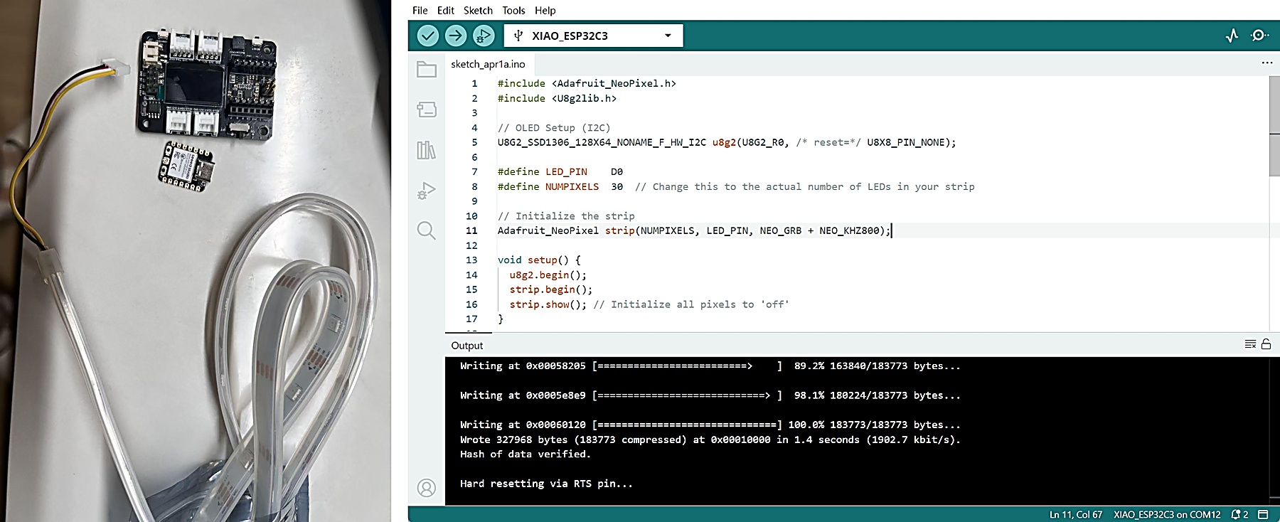
Goal: Control the entire LED strip with real-time brightness feedback on the OLED.
#include <Adafruit_NeoPixel.h>
#include <U8g2lib.h>
#include <Wire.h>

// OLED Setup (I2C) - Explicitly defining pins for ESP32C3
U8G2_SSD1306_128X64_NONAME_F_HW_I2C u8g2(U8G2_R0, /* reset=*/ U8X8_PIN_NONE, /* clock=*/ 7, /* data=*/ 6);

#define LED_PIN    D0
#define NUMPIXELS  30

Adafruit_NeoPixel strip(NUMPIXELS, LED_PIN, NEO_GRB + NEO_KHZ800);

void setup() {
  Wire.begin(6, 7); // SDA, SCL
  u8g2.begin();
  strip.begin();
  strip.show();
}

void updateLEDDisplay(int brightness, const char* phase) {
  u8g2.clearBuffer();
  u8g2.setFont(u8g2_font_ncenB08_tr);
  u8g2.drawStr(0, 15, "DEVICE: LED STRIP");
  u8g2.drawLine(0, 20, 128, 20);

  u8g2.drawStr(0, 40, "Phase:");
  u8g2.drawStr(50, 40, phase);

  u8g2.drawStr(0, 55, "Brightness:");
  int percent = map(brightness, 0, 150, 0, 100);
  u8g2.setCursor(85, 55);
  u8g2.print(percent);
  u8g2.print("%");

  u8g2.sendBuffer();
}

void loop() {
  for(int brightness=0; brightness<150; brightness++) {
    for(int n=0; n<NUMPIXELS; n++) {
      strip.setPixelColor(n, strip.Color(brightness, brightness, 0));
    }
    strip.show();
    if(brightness % 10 == 0) updateLEDDisplay(brightness, "Inhaling...");
    delay(10);
  }

  for(int brightness=150; brightness>=0; brightness--) {
    for(int n=0; n<NUMPIXELS; n++) {
      strip.setPixelColor(n, strip.Color(brightness, brightness, 0));
    }
    strip.show();
    if(brightness % 10 == 0) updateLEDDisplay(brightness, "Exhaling...");
    delay(15);
  }
}
Code Explanation & Debug:
- Visual Animation Logic: The "breathing" effect is created using a nested loop that progressively increments and decrements the RGB PWM values.
- Color Composition: Yellow is synthesized by mixing Red and Green at identical intensity levels ($R=G, B=0$).
- OLED Sync: To prevent the I2C display update from causing "stutters" in the LED animation, the screen is refreshed only every 10 brightness steps using the modulo operator (
% 10). - Pixel Density Configuration: Initially, only the first LED lit up. This was corrected by setting
NUMPIXELSto match the actual count (30) of the strip, ensuring the data signal is shifted through the entire daisy-chain. - Upload / Bootloader Mode: When the XIAO ESP32C3 upload failed or the serial port was not recognized, I first tried pressing the RESET button once. If that did not work, I manually entered bootloader mode by holding the BOOT button, connecting the board to the computer, and then releasing BOOT. This is different from UF2-based boards where double-clicking RESET is commonly used.
- Hardware Interfacing: Using the
Adafruit_NeoPixellibrary allows for precise timing-sensitive serial data transmission to the WS2813 chips.
Project B: Massage Rhythmic Servo (Mechanical)
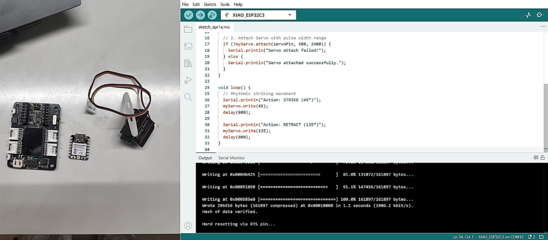
Goal: Focus on pure mechanical output and avoid the instability I observed when running the OLED and servo together.
#include <ESP32Servo.h>

// Removed OLED code to focus on Servo stability
Servo myServo;
const int servoPin = D5; // GPIO 7

void setup() {
  Serial.begin(115200);

  // 1. Critical Servo PWM Allocation
  ESP32PWM::allocateTimer(0);
  ESP32PWM::allocateTimer(1);

  myServo.setPeriodHertz(50); // Standard 50Hz

  // 2. Attach Servo with pulse width range
  if (!myServo.attach(servoPin, 500, 2400)) {
    Serial.println("Servo attach failed!");
  } else {
    Serial.println("Servo attached successfully.");
  }
}

void loop() {
  // Rhythmic striking movement
  Serial.println("Action: STRIKE (45°)");
  myServo.write(45);
  delay(800);

  Serial.println("Action: RETRACT (135°)");
  myServo.write(135);
  delay(800);
}
Debug & Troubleshooting Record :
- Initial Failure: Uploading the code resulted in no movement. Serial Monitor reported "Error: Servo Attachment Failed!".
- Root Cause 1 (Pin Mapping): The servo was physically connected to the top-right Grove connector on the Expansion Board. My initial code used
D1, but the tested connector was controlled byD5 / GPIO7, so I corrected the servo pin definition toD5. - Root Cause 2 (Servo PWM Setup): In my ESP32Servo setup, adding
ESP32PWM::allocateTimer()helped the servo attach and move correctly. This made the PWM setup more explicit and reduced the chance of timer-related problems. - Root Cause 3 (Combined Output Instability): When I tried to run the OLED and servo together, the OLED showed visual noise and the program sometimes became unstable. Since
D5 / GPIO7is also the I2C SCL pin, and the servo also adds a noisy mechanical load, I separated the tests instead of treating this as a reliable combined setup. For the servo project, I removed the OLED code and focused on stable mechanical movement only. - Final Result: By correcting the pin to
D5and stripping down the code to its mechanical core, the rhythmic movement is now stable and responsive.
24V COB LED Strip Power Test for Final Project
For the final project, I plan to use a 24V COB LED strip as the main light output. Compared with the programmable LED strip used in the web control test, the COB LED strip is more suitable for the final cushion because it gives a softer and more continuous light, without visible individual LED dots.
This part is a preparation test for the final light system. Before connecting the 24V COB LED strip to my custom board, I tested it separately with a bench power supply to check the real voltage, current, power consumption, brightness, and heat behavior.
At this stage, this is a power test only. The 24V COB LED strip has not yet been connected to my custom board, because it still needs a MOSFET or switching module.
Final light output plan
→ 24V COB LED strip
→ bench power supply test first
→ record V / A / W
→ check brightness and heat
→ decide normal working range
→ connect to custom board later through MOSFET / switching module
Materials and Tools Used
24V COB LED strip
→ temporary power wires / clips
→ bench power supply
→ V / A / W display reading
→ photo documentation
| Item | Purpose |
|---|---|
| 24V COB LED strip | Main light output planned for the final cushion |
| Bench power supply | Provides controlled voltage and current for testing |
| Power wires | Connect the LED strip to the power supply |
| Wire connectors / clips | Help make a temporary test connection |
| Camera / phone | Record the test setup and result |
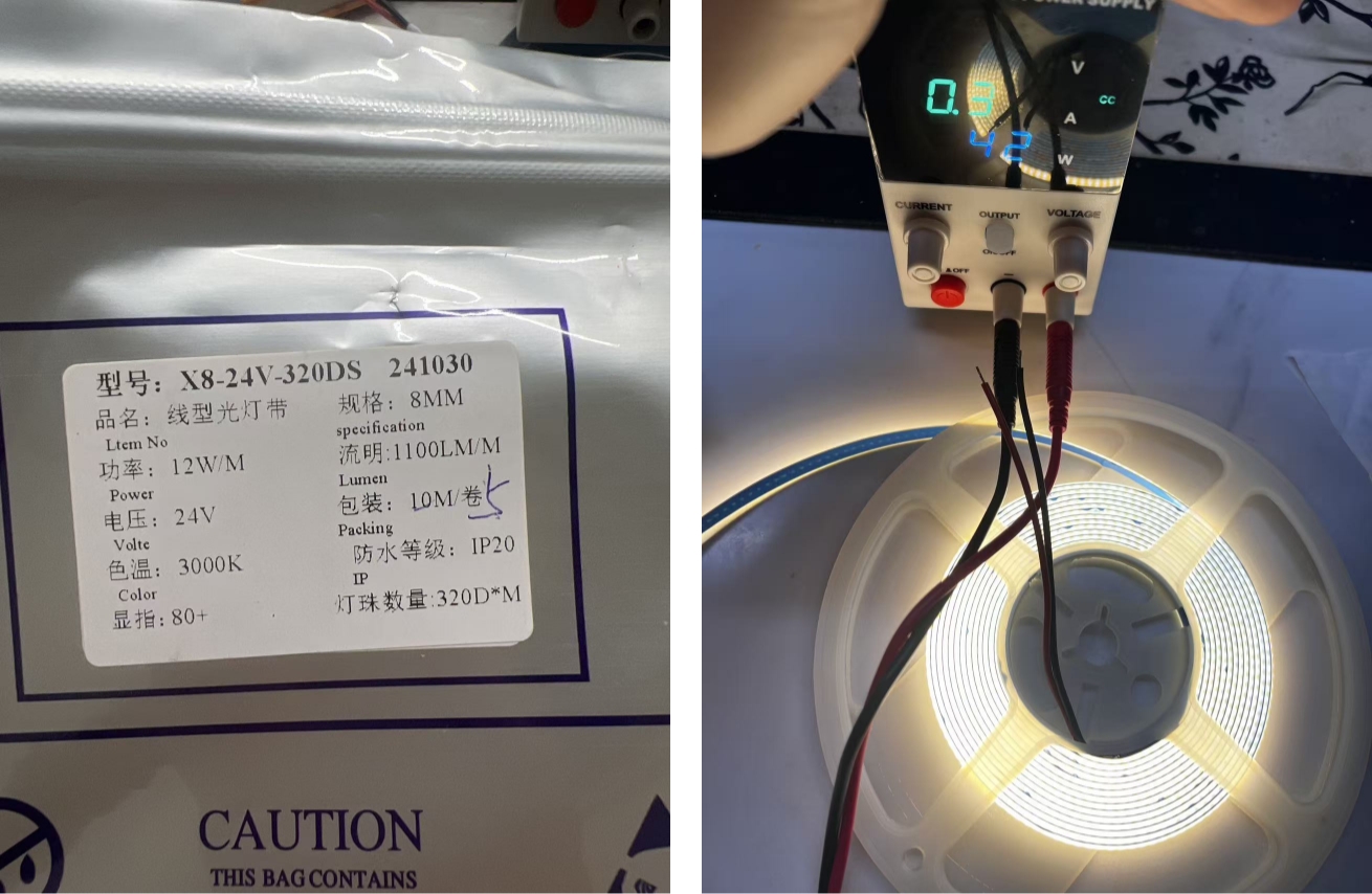
LED Strip Parameters
| Item | Parameter | Notes |
|---|---|---|
| LED strip type | 24V COB LED strip | Continuous soft light |
| Tested length | 1.35 m | Cut section for the cushion prototype |
| Rated voltage | 24 V | Tested with a bench power supply |
| Supplier nominal power | about 12 W/m | Reference value from product information |
| Estimated nominal power for 1.35 m | about 16.2 W | 12 W/m × 1.35 m |
| Measured lower-current setting | 22.7 V / 0.30 A / about 6.8 W | Bright enough for soft feedback |
| Measured higher-current setting | 24.0 V / 0.57 A / 13.68 W | Brighter, but more heat |
| Selected working current | around 0.30 A | Chosen for normal use |
| Selected working power | about 6.8 W | Enough brightness with lower heat |
Test Workflow
Prepare COB LED strip
→ check polarity
→ connect to bench power supply
→ set voltage around 24 V
→ start from low current
→ increase current slowly
→ record V / A / W values
→ compare brightness and heat
→ choose safer working range for the final cushion
The test was used to understand the actual working range of the COB LED strip before system integration. I mainly compared two states: a lower-current state that was already bright enough, and a higher-current state that showed the upper brightness range but produced more heat.
Power Test Result
Power supply display
→ voltage
→ current
→ power
→ brightness observation
→ heat consideration
| Test | Voltage | Current | Power | Observation |
|---|---|---|---|---|
| Lower current test | 22.7 V | 0.30 A | about 6.8 W | Already bright enough for soft visual feedback |
| Higher current test | 24.0 V | 0.57 A | 13.68 W | Brighter, but heat needs more attention |
Test Result
The COB LED strip worked normally with the bench power supply. At around 0.30 A / about 6.8 W, the brightness was already enough for the visual feedback I need in the final cushion.
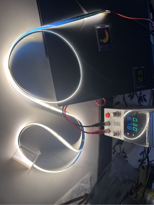
When the current was increased to around 0.57 A, the strip became brighter, but the heat also became more important to consider. Since the final project only needs a soft light effect around the base of the cushion, I do not need to run the strip at the higher-current level.
Decision for Final Project
Enough brightness at 0.30 A
→ lower heat
→ safer for cushion structure
→ selected as normal working range
From the power test, I decided to use around 0.30 A / about 6.8 W as the normal working range for the final project.
This decision is based on three reasons:
- The brightness is already enough for soft visual feedback.
- Lower current can reduce heat.
- The cushion does not need strong lighting; it only needs a visible and gentle light response.
The higher-current test helped me understand the upper brightness range, but I do not plan to use that level continuously.
Limitation after the Bench Power Test
At this stage, the 24V COB LED strip has been tested with a bench power supply, but it has not yet been connected to my custom board.
The reason is that the 24V COB LED strip needs a proper switching module or MOSFET circuit. The microcontroller pin cannot drive the 24V strip directly. The microcontroller should only send a control signal, while the external 24V power supply provides power to the LED strip.
The final workflow will be:
Web interface
→ custom board
→ switching module / MOSFET
→ 24V COB LED strip
At this stage, the next step was to add a MOSFET module so the microcontroller could control the 24V COB LED strip safely through a PWM signal.
Update: 24V COB LED Strip Controlled with a MOSFET Module
After the first bench power test of the 24V COB LED strip, I received the MOSFET switch module.
I continued the output device test and tried to control the COB LED strip using the XIAO ESP32C3.
In the earlier test, the COB LED strip was only powered directly by the DC power supply.
In this update, I added the MOSFET module between the DC power supply and the COB LED strip.
Summary
XIAO ESP32C3 sends a PWM signal
➡ MOSFET module receives the signal
➡ MOSFET module controls the brightness of the 24V COB LED strip
The XIAO ESP32C3 does not power the COB LED strip directly.
The 24V COB LED strip is still powered by the DC power supply.
The XIAO only sends a low-voltage PWM control signal to the MOSFET module.
System Setup
For this test, I separated the power supply into two parts.
Computer USB -> XIAO ESP32C3

DC Power Supply -> MOSFET Module -> 24V COB LED Strip
The USB cable powers the XIAO ESP32C3 and is also used for programming.
The DC power supply only powers the 24V COB LED strip.
The MOSFET module works as an electronic switch.
It allows the low-voltage PWM signal from the XIAO ESP32C3 to switch and dim the 24V COB LED strip.
MOSFET Module Check
Before wiring, I carefully checked the labels on the MOSFET module to confirm the pin layout.
Power Side
VIN+
VIN-
VOUT+
VOUT-
VIN+ / VIN-= 24V power inputVOUT+ / VOUT-= controlled LED output
Control Side
GND
TRIG / PWM
GND= common groundTRIG / PWM= PWM signal input
This specific MOSFET module does not require a 3V3 connection from the XIAO ESP32C3.
For the control side, I only connected:
XIAO GND -> MOSFET GND
XIAO D2 / GPIO4 -> MOSFET TRIG / PWM
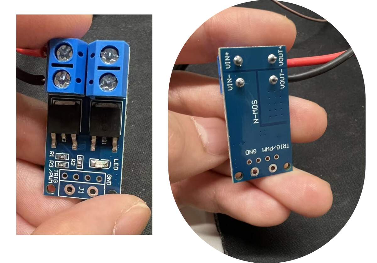
Checking the labels on the back of the MOSFET module
Wiring
The wiring configuration for this test was:
| From | To | Function |
|---|---|---|
| DC Power Supply +24V | MOSFET VIN+ | 24V power input |
| DC Power Supply - | MOSFET VIN- | 24V power ground |
| MOSFET VOUT+ | COB LED Strip + | Controlled LED positive output |
| MOSFET VOUT- | COB LED Strip - | Controlled LED negative output |
| XIAO ESP32C3 GND | MOSFET GND | Common ground |
| XIAO ESP32C3 D2 / GPIO4 | MOSFET TRIG / PWM | PWM control signal |
| Computer USB | XIAO ESP32C3 | Board power and programming |
Safety Notes
24V must not be connected to the XIAO ESP32C3 3V3, 5V, or any GPIO pin.
Only GND is shared between the 24V power system and the microcontroller control system.
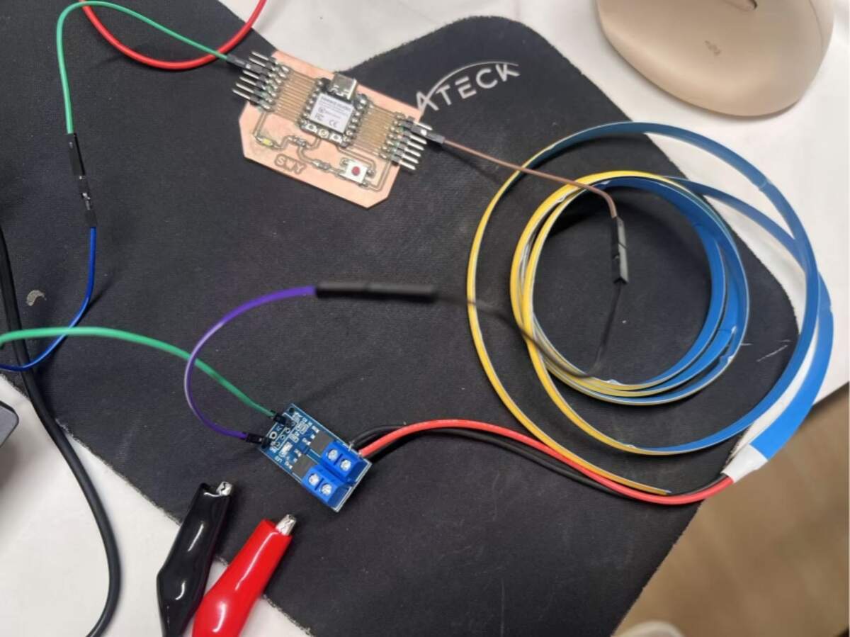
System wiring diagram for the MOSFET control test
Power Safety Setup
Before turning on the DC power supply, I checked the wiring order carefully.
1. DC Power Supply +24V -> MOSFET VIN+
2. DC Power Supply - -> MOSFET VIN-
3. MOSFET VOUT+ -> COB LED Strip +
4. MOSFET VOUT- -> COB LED Strip -
5. XIAO ESP32C3 GND -> MOSFET GND
6. XIAO ESP32C3 D2 / GPIO4 -> MOSFET TRIG / PWM
For the first test, I used a conservative power setting.
Voltage: 24V
Current limit: around 0.30A
I used this lower current limit because the COB LED strip was already bright enough at this level during the previous bench power test.
I also unfolded the LED strip during testing to reduce heat buildup.
Testing Process
1. Basic PWM Control
Before testing the breathing light effect, I first checked whether the MOSFET module responded correctly to the PWM signal.
Lower PWM value -> LED dimmer
Higher PWM value -> LED brighter
After confirming the PWM control worked correctly, I continued to the breathing light test.
2. Breathing Light Test
After the basic PWM control worked, I uploaded a breathing light program to the XIAO ESP32C3.
For the first breathing light test, I did not use the full brightness range.
I limited the maximum PWM value to 160 out of 255.
This was bright enough to observe the light effect clearly and was safer for the first test.
Testing the MOSFET-controlled 24V COB LED strip with the XIAO ESP32C3 and DC power supply
Code
#include <Arduino.h>

// Seeed Studio XIAO ESP32C3
// D2 = GPIO4
#ifndef D2
#define D2 4
#endif

const int MOS_PIN = D2;

// PWM settings
const int PWM_FREQ = 1000;
const int PWM_RES  = 8;

// Limit the maximum brightness for the first test
const int MIN_DUTY = 0;
const int MAX_DUTY = 160;

// Breathing timing
const int BREATH_PERIOD_MS = 4000;
const int STEP_DELAY_MS = 20;

// Change to true if the MOSFET module works in reverse logic
const bool INVERT_PWM = false;

#if defined(ESP_ARDUINO_VERSION_MAJOR) && ESP_ARDUINO_VERSION_MAJOR >= 3

void setupPWM() {
  ledcAttach(MOS_PIN, PWM_FREQ, PWM_RES);
}

void writePWM(int duty) {
  duty = constrain(duty, 0, 255);

  if (INVERT_PWM) {
    duty = 255 - duty;
  }

  ledcWrite(MOS_PIN, duty);
}

#else

const int PWM_CH = 0;

void setupPWM() {
  ledcSetup(PWM_CH, PWM_FREQ, PWM_RES);
  ledcAttachPin(MOS_PIN, PWM_CH);
}

void writePWM(int duty) {
  duty = constrain(duty, 0, 255);

  if (INVERT_PWM) {
    duty = 255 - duty;
  }

  ledcWrite(PWM_CH, duty);
}

#endif

void setup() {
  Serial.begin(115200);

  setupPWM();
  writePWM(0);

  delay(1000);

  Serial.println("24V COB breathing test start");
  Serial.println("XIAO ESP32C3 D2/GPIO4 -> MOSFET TRIG/PWM");
}

void loop() {

  for (int t = 0; t < BREATH_PERIOD_MS; t += STEP_DELAY_MS) {

    float phase = (float)t / BREATH_PERIOD_MS * TWO_PI;

    // Smooth breathing curve
    float breath = 0.5 - 0.5 * cos(phase);

    int duty = MIN_DUTY + breath * (MAX_DUTY - MIN_DUTY);

    writePWM(duty);

    delay(STEP_DELAY_MS);
  }
}
Code Notes
In this code, D2 / GPIO4 is used as the PWM output pin.
XIAO ESP32C3 D2 / GPIO4 -> MOSFET TRIG / PWM
The PWM duty value controls the brightness of the COB LED strip.
0   = off or very dim
160 = maximum brightness used in this test
255 = full PWM value, not used in this first test
The breathing effect is created with a cosine curve.
dark -> brighter -> brightest -> darker -> repeat
This makes the light transition smoother than a simple step-by-step fade.
Result
The breathing light test worked successfully.
The XIAO ESP32C3 was powered by USB.
The 24V COB LED strip was powered separately by the DC power supply.
The MOSFET module received the PWM signal from the XIAO ESP32C3 and controlled the brightness of the COB LED strip correctly.
The COB LED strip showed a smooth breathing light effect.
Successful 24V COB breathing light effectThis bench test confirmed that the 24V COB LED strip can be controlled with a MOSFET module and PWM signal. For the final cushion, I still need to test the same circuit inside the actual structure with the battery, wiring, and sensor input.
What I Learned
This test helped me understand how to separate the control side and the power side when working with a 24V output device.
For small LEDs, the microcontroller can sometimes drive the LED directly.
However, for a 24V COB LED strip, the microcontroller should only send the control signal.
The correct control logic is:
XIAO ESP32C3 -> sends PWM signal
MOSFET module -> switches and dims the 24V output
DC power supply -> powers the COB LED strip
The most important part of this test was checking the labels on the MOSFET module before wiring.
Different MOSFET modules may have different pin layouts, so I should not rely only on wire colors.
For this module, the final control connection was:
XIAO GND -> MOSFET GND
XIAO D2 / GPIO4 -> MOSFET TRIG / PWM
The 24V power stayed only in this path:
DC Power Supply -> MOSFET Module -> COB LED Strip
This test is useful for my final project because the COB LED strip will become the main light output of the cushion.