10-Output-Devices
Reflection
This week while learning output devices, I first tried to interface an OLED screen, but after powering it on, I encountered issues like screen glitching and flickering. Using a multimeter to measure each pin, I found that the SDA pin voltage was only 0.23V (it should be pulled high to 3.3V during idle). After disconnecting the screen, the pin recovered to 3.3V, leading me to conclude that the OLED module was damaged, causing I2C communication failure. I may need to purchase a new screen.
After the screen debugging, I moved on to another output device: servo motors. Servo motors are small and operate at 4.8-6V, which fits well with my final project. I tried two motors: one 180-degree servo and one 360-degree continuous rotation servo, both controlled using the Servo.h library. The 180-degree servo allows precise angle control via write(angle), while the 360-degree servo actually controls speed and direction. Since I had never connected a 5V device before, I specifically soldered a 5V pin to power the servos. Although I faced setbacks with the screen, the systematic troubleshooting process (measuring voltages first, then isolating the faulty module) deepened my understanding of voltage matching and I2C bus logic levels. Meanwhile, the successful driving of the servo motors provided a reliable solution for mechanical actuation in my project.
Group Assignment
- [x] measure the power consumption of an output device
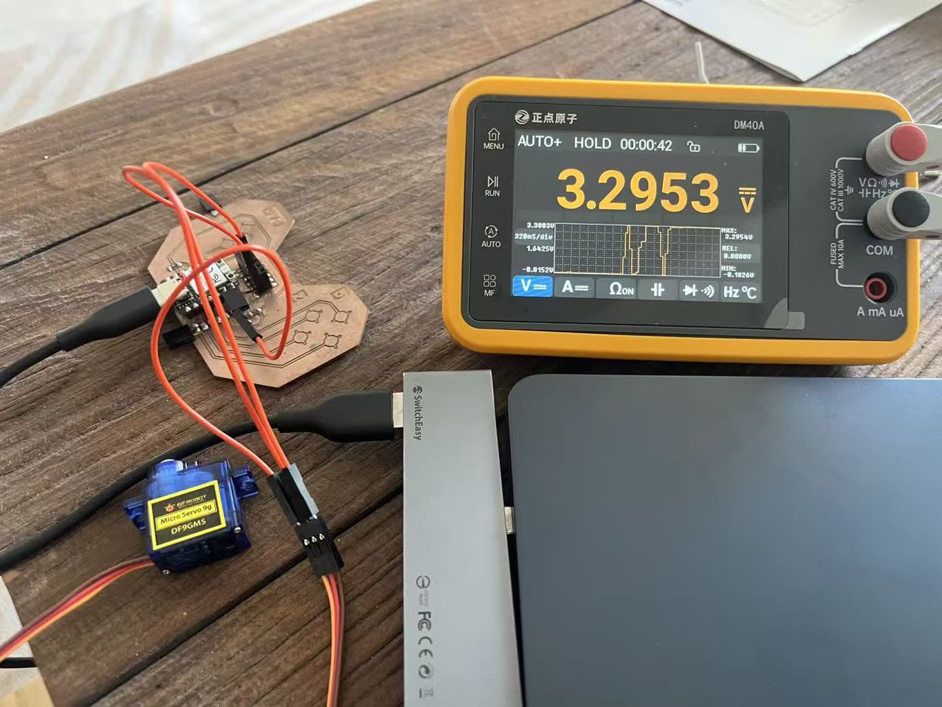 I use multimeter to mesure the voltage of servo motor. The red probe (positive) connects to the power, and the black probe(negtive) connects to the ground. I put it in working voltage as 3.3V and the test result is 3.29V.
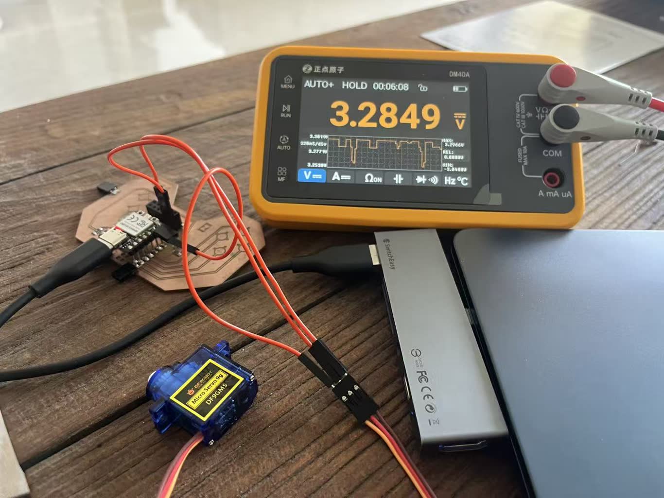 When I press the touch pad to triger the movement of the servo motor. The voltage The voltage has been pulled down. We can see it through the map. When not in use, it returns to its original voltage.
I put it in 5V, and nothing change durning the working.
I try to block the movement of servo motor, its voltage suddenly decrease to 4.8V.
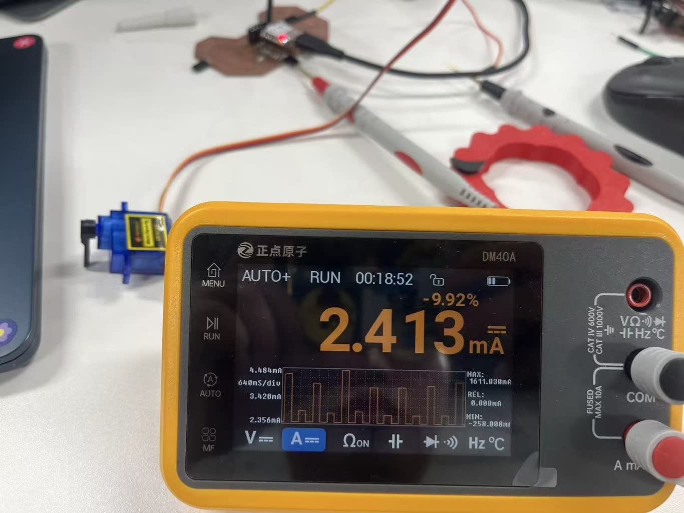
To test current, we need to connect mutimeter and the circit in series, which means the red probe connects to the board power, and the black probe connects to the power pin of servo motor. Then we can see the static current of servo motor is 2.413mA.
Then I set the testing program to test servo motor from static to work, slow to fast, we can notic the current is increasing. And its working current is around 19mA.
P = U x I = 5 x 0.019 = 0.095W
the no load power is around 0.1W
If I block servo motor, the current goes up to 340mA.
P = U x I = 5 x 0.340 = 1.7W
the stall power is around 1.7W
Individual Assignment
- [x] add an output device to a microcontroller board you've designed, and program it to do something
I2C Screen
Screen DeBuging
-
Measure the power supply voltage of OLED
-
Set the multimeter to the DC voltage range (DCV) and select the 20V range (if the automatic range is available, no selection is required).
-
Connect the black probe to the GND (common ground) on the circuit board (such as any GND pin of RP2040).
-
Connect the red probe to the VCC pin of the OLED module (usually "VCC" or "VDD" on the module).
-
Read the voltage value:
-
If the display shows around 3.3V > The module should be powered by 3.3V.
-
If the display shows around 5.0V > The module should be powered by 5V.
-
If the display shows 0V or much lower than 3V > There is a power supply failure (wiring error, damaged voltage regulator, short circuit of the load, etc.).
-
If the voltage fluctuates between 2 and 4V > The power supply is unstable. It might be due to insufficient current or poor contact.
-
Measure the voltage of the SDA or SCL pins relative to ground:
-
The idle voltage should be 3.3V (due to internal or external pull-up resistors).
-
During communication, the voltage fluctuates rapidly between 0V and 3.3V. The multimeter will display an average value (approximately 1.65V), which is normal.
-
If the idle voltage is lower than 2.5V, it indicates that the pull-up resistor is too small or there is a short circuit or leakage.
Servo Motor
#include <Servo.h>

Servo myservo;  // create servo object to control a servo
// twelve servo objects can be created on most boards

int pos = 0;    // variable to store the servo position

void setup() {
  myservo.attach(D5);  // attaches the servo on pin 9 to the servo object
}

void loop() {
  for (pos = 0; pos <= 180; pos += 1) { // goes from 0 degrees to 180 degrees
    // in steps of 1 degree
    myservo.write(pos);              // tell servo to go to position in variable 'pos'
    delay(15);                       // waits 15ms for the servo to reach the position
  }
  for (pos = 180; pos >= 0; pos -= 1) { // goes from 180 degrees to 0 degrees
    myservo.write(pos);              // tell servo to go to position in variable 'pos'
    delay(15);                       // waits 15ms for the servo to reach the position
  }
}
#include <Servo.h>

// servo pin
#define SERVO_PIN D5

// touchpad pin (D0~D3 > GPIO26~29)
#define N_TOUCH 4
int touch_pins[N_TOUCH] = {26, 27, 28, 29};
int threshold[N_TOUCH] = {20, 20, 20, 20};   // threshold

bool pin_touched_now[N_TOUCH] = {false};
bool pin_touched_past[N_TOUCH] = {false};

// servo define
Servo myServo;

// angle
int currentAngle = 90;    // initial 90°
int stepAngle = 10;        // per degree

// toughpad
void update_touch() {
  int t, t_max = 200;
  int p;

  for (int i = 0; i < N_TOUCH; i++) {
    p = touch_pins[i];

    // Reduce crosstalk
    for (int j = 0; j < N_TOUCH; j++) {
      if (j != i) pinMode(touch_pins[j], INPUT);
    }

    // Measurement
    pinMode(p, OUTPUT);
    digitalWriteFast(p, LOW);
    delayMicroseconds(25);
    pinMode(p, INPUT_PULLUP);

    t = 0;
    while (!digitalReadFast(p) && t < t_max) t++;

    // updateing
    pin_touched_past[i] = pin_touched_now[i];
    pin_touched_now[i] = (t > threshold[i]);
  }
}

// set angle and print
void setServoAngle(int angle) {
  angle = constrain(angle, 0, 180);
  myServo.write(angle);
  currentAngle = angle;
  Serial.print("angle: ");
  Serial.println(angle);
}

void setup() {
  Serial.begin(9600);
  myServo.attach(SERVO_PIN);
  setServoAngle(currentAngle);   // initial angle

void loop() {
  update_touch();

  // D0 angle increase
  if (pin_touched_now[0] && !pin_touched_past[0]) {
    int newAngle = currentAngle + stepAngle;
    if (newAngle > 180) newAngle = 180;
    setServoAngle(newAngle);
    Serial.println("D0:angle increase");
  }

  // D1 angle decrease
  if (pin_touched_now[1] && !pin_touched_past[1]) {
    int newAngle = currentAngle - stepAngle;
    if (newAngle < 0) newAngle = 0;
    setServoAngle(newAngle);
    Serial.println("D1:angle decrease");
  }

  // D2 point to 0°
  if (pin_touched_now[2] && !pin_touched_past[2]) {
    setServoAngle(0);
    Serial.println("D2:to 0°");
  }

  // D3 point to 180°
  if (pin_touched_now[3] && !pin_touched_past[3]) {
    setServoAngle(180);
    Serial.println("D3:to 180°");
  }

  delay(50);
}
180° servo motor can control its angle.
360° servo motor can control its speed.