Week 09: Input Devices
Assignment
Group Assignment
- Probe the analog levels and digital signals of an input device.
- Use lab test equipment to observe the signal.
- As a minimum, demonstrate the use of a multimeter and an oscilloscope.
- Document the group work on the group work page.
- Reflect on what I learned from the group work on my individual page.
Individual Assignment
- Measure something.
- Add a sensor to a microcontroller board that I have designed.
- Read the sensor data from the board.
Overview
This week, I explored creating a low-cost input sensor for my final project. I developed a binary contact switch using copper foil and a XIAO ESP32-C3, focusing on the basic logic of digital input before moving to complex pressure sensing.
Group Assignment Reflection
Group documentation link:
Yanfeng Li's Week 09 group documentation
Additional video evidence:
Group measurement test video on YouTube
In the group assignment, we learned how to use basic lab measurement tools for input devices, including a multimeter and an oscilloscope.
The group documentation page was handled by another team member, Yanfeng Li. He will update the group page later, but the measurement test video has already been uploaded to YouTube, so I added the video link here first as supporting evidence.
I learned that a multimeter is useful for checking continuity, voltage, GND connections, and possible short circuits. An oscilloscope is useful for observing how an input signal changes over time, such as whether the signal is stable, noisy, or switching correctly.
This helped me understand that when a control board has problems, I should not only look at the code. I also need to check the circuit again with measurement tools, especially the power, ground, signal pins, and sensor output.
Individual Assignment: Copper Foil Contact Switch
References & Resources
| Resource | Link |
|---|---|
| Adrián Torres — FabriXiao | View Project |
| Adrián Torres — Step Response | View Project |
| XIAO ESP32-C3 Pin Multiplexing | Official Wiki |
| Fab Academy 2020 — Adrian Torres / FabriXiao Pressure Sensor with Velostat | View Reference |
| Fab Academy 2026 — Javier Vega / Velostat Fabric Sensor | View Reference |
| Fab Academy 2021 — Carla Molins / Testing Velostat Layer with Multimeter | View Reference |
| Fab Academy 2023 — Pedro Candeias / FSR Made with Velostat | View Reference |
Materials & BOM
| Item | Description |
|---|---|
| ① XIAO ESP32-C3 | Main controller for input processing. |
| ② Copper Foil Tape | Used as conductive contact surfaces. |
| ③ Spacer Material | Paper and tape to create an air gap. |
| ④ Connection | Jumper wires and USB-C cable. |
| ⑤ Software | Arduino IDE for coding and Serial monitoring. |
Note: This version does NOT use LEDs, external resistors, Velostat, or conductive fabric. It is a first copper foil contact switch test. I researched Velostat through references as a possible DIY pressure-sensitive material and made only a very small informal check for basic understanding, but I did not develop it into a complete sensor during this week.
Board Used for This Test
For this input test, I used my own designed microcontroller board as the main controller board. The copper foil contact sensor was connected to the board through the input pin and GND.
Signal pin → upper copper foil
GND → lower copper foil
The board reads the state of the copper foil sensor and sends the result to the Serial Monitor. This allowed me to test whether the sensor could be used as an input device for my final project.
Wiring & Logic
Wiring Diagram
- D4 ➡ Upper copper foil (Signal)
- GND ➡ Lower copper foil (Ground)
- USB-C ➡ Computer (Power & Data)
Logic Explanation
I used the internal INPUT_PULLUP resistor, which simplifies the circuit by removing the need for external resistors.
- Idle State: D4 is pulled HIGH by the internal resistor ➡
pressed:0. - Contact State: Two copper layers touch, connecting D4 directly to GND ➡
pressed:1.
Circuit Logic: Open Circuit and Closed Circuit
This sensor works by changing the circuit between an open state and a closed state.
Open Circuit
When the two copper foil layers are not touching, the circuit is open. The signal pin is not connected to GND. Because I used INPUT_PULLUP, the microcontroller keeps the input pin at HIGH.
Copper foil separated
→ circuit open
→ input pin pulled HIGH
→ pressed:0
Closed Circuit
When the two copper foil layers touch, the signal pin is directly connected to GND. The input becomes LOW. In the code, LOW is treated as the pressed state.
Copper foil touching
→ circuit closed
→ signal pin connected to GND
→ input reads LOW
→ pressed:1
This is why the sensor gives a clear digital result. It is not trying to measure a changing resistance. It only checks whether the electrical path is connected or disconnected.
Why I Used INPUT_PULLUP
In this test, I did not use an external resistor. Instead, I used the internal pull-up resistor inside the microcontroller by setting the pin mode to:
pinMode(PRESS_PIN, INPUT_PULLUP);
This is important because a digital input pin should not be left floating. If a pin is floating, it may randomly read HIGH or LOW because it is not connected to a stable voltage.
The internal pull-up resistor gives the input pin a default state:
Default state → HIGH
Touched state → LOW
This makes the circuit simple and stable for a contact switch.
This also means that the circuit still uses a resistor. It is just inside the microcontroller, not added externally on the board.
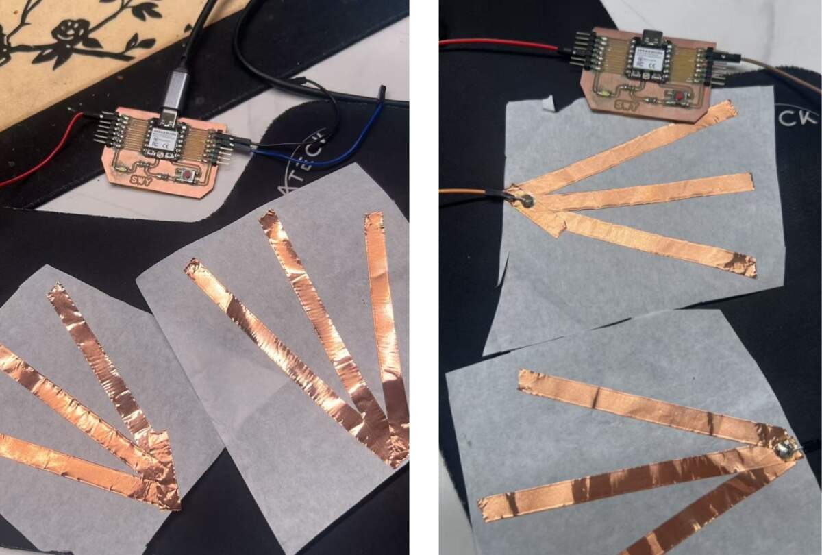
Fabrication Process
Sandwich Structure
I cut two pieces of copper foil and used paper/tape to create a simple layered structure:
- Top Layer: Copper foil connected to D4.
- Middle Layer: Paper spacer with an air gap.
- Bottom Layer: Copper foil connected to GND.
Testing the Contact
Initially, I tried using a sponge to press the layers, but it failed to trigger. I realized that since the sponge is non-conductive, it only works if the force is strong enough to make the two copper surfaces physically touch.
Signal Observation
The copper foil sensor showed a very clear signal change when the two conductive surfaces touched.
In the idle state, the two copper foil layers were separated. The input pin was pulled HIGH by the internal pull-up resistor, so the Serial Monitor showed:
pressed:0, value:0, holdTime:0
When the two copper foil layers touched, the signal pin was connected to GND. The input changed to LOW, and the code interpreted this as a pressed state:
pressed:1, value:100, holdTime:[ms]
The result was stable for detecting contact. This means the copper foil structure works well as a simple digital switch.
However, this test does not measure pressure intensity. It only detects whether the circuit is open or closed. Therefore, it can clearly answer:
Is there contact? → Yes / No
But it cannot answer:
How much pressure is applied? → Not yet
Code Implementation
// Ambient Nodes V1
// Copper foil contact switch with debounce and hold time
// Board: XIAO ESP32-C3

const int PRESS_PIN = D4;

bool stablePressed = false;
bool lastReading = false;

unsigned long lastDebounceTime = 0;
unsigned long pressStartTime = 0;

const unsigned long debounceDelay = 30; // 30ms debounce

void setup() {
  Serial.begin(115200);
  delay(1000);

  pinMode(PRESS_PIN, INPUT_PULLUP); // Use internal pull-up
}

void loop() {
  // Read the raw state (LOW means pressed due to PULLUP)
  bool readingPressed = digitalRead(PRESS_PIN) == LOW;

  // Debounce logic
  if (readingPressed != lastReading) {
    lastDebounceTime = millis();
    lastReading = readingPressed;
  }

  if ((millis() - lastDebounceTime) > debounceDelay) {
    if (readingPressed != stablePressed) {
      stablePressed = readingPressed;

      if (stablePressed) {
        pressStartTime = millis(); // Record start time
      }
    }
  }

  // Output values
  int value = stablePressed ? 100 : 0;
  unsigned long holdTime = stablePressed ? millis() - pressStartTime : 0;

  Serial.print("pressed:");
  Serial.print(stablePressed ? 1 : 0);
  Serial.print(", value:");
  Serial.print(value);
  Serial.print(", holdTime:");
  Serial.println(holdTime);

  delay(50);
}
Code Explanation
The code reads the copper foil contact sensor as a digital input.
Pin Definition
const int PRESS_PIN = D4;
This line defines which pin is connected to the copper foil sensor. In this test, the signal layer of the copper foil is connected to D4.
State Variables
bool stablePressed = false;
bool lastReading = false;
These variables store the sensor state. lastReading stores the raw reading from the previous loop. stablePressed stores the confirmed state after debounce.
Timing Variables
unsigned long lastDebounceTime = 0;
unsigned long pressStartTime = 0;
const unsigned long debounceDelay = 30;
These variables are used for timing. lastDebounceTime records when the sensor reading last changed. pressStartTime records when the press started. debounceDelay is set to 30 ms to avoid false triggering caused by unstable contact.
Setup
Serial.begin(115200);
pinMode(PRESS_PIN, INPUT_PULLUP);
Serial.begin(115200) starts serial communication so I can see the sensor data in the Serial Monitor.
INPUT_PULLUP turns on the internal pull-up resistor. This means the pin stays HIGH when the copper layers are not touching. When the copper layers touch, the pin connects to GND and reads LOW.
Reading the Sensor
bool readingPressed = digitalRead(PRESS_PIN) == LOW;
Because I used INPUT_PULLUP, the logic is inverted. LOW means the sensor is pressed, and HIGH means the sensor is not pressed.
Debounce Logic
if (readingPressed != lastReading) {
  lastDebounceTime = millis();
  lastReading = readingPressed;
}
When the reading changes, the code records the time of the change. This helps filter out unstable contact noise.
if ((millis() - lastDebounceTime) > debounceDelay) {
  if (readingPressed != stablePressed) {
    stablePressed = readingPressed;

    if (stablePressed) {
      pressStartTime = millis();
    }
  }
}
Only when the reading stays stable for more than 30 ms does the code accept it as the real sensor state. If the sensor becomes pressed, the code records the start time.
Output Values
int value = stablePressed ? 100 : 0;
unsigned long holdTime = stablePressed ? millis() - pressStartTime : 0;
The code converts the digital state into a simple value:
Not pressed → value:0
Pressed → value:100
It also calculates holdTime, which shows how long the sensor has been pressed.
Serial Monitor Output
Serial.print("pressed:");
Serial.print(stablePressed ? 1 : 0);
Serial.print(", value:");
Serial.print(value);
Serial.print(", holdTime:");
Serial.println(holdTime);
The Serial Monitor prints three values:
pressed → whether the copper foil is touching
value → simple 0 / 100 output
holdTime → how long the contact has lasted
This output is useful for my final project because sitting is not only a pressure event. The duration of sitting can also become part of the interaction logic.
Problem & Solution
Problem: Non-conductive Trigger Failure
Pressing the surface with non-conductive materials, like a sponge, did not change the Serial Monitor values.
Solution: Physical Contact Verification
The current version is a digital contact switch, not an analog pressure sensor. It requires the two copper surfaces to physically touch to close the circuit.
- ✅ Working: Copper surface touches copper surface ➡
pressed:1. - ❌ Not working: Sponge presses the surface but copper layers remain separated ➡
pressed:0.
Results & Limitations
Test Results
The test was successful. The Serial Monitor correctly identified the binary states:
- Idle:
pressed:0, value:0, holdTime:0 - Pressed:
pressed:1, value:100, holdTime:[ms]
Limitations
- ✅ Binary only (0 or 100).
- ❌ No pressure intensity measurement.
- ⚠️ Sensitivity depends entirely on the mechanical contact and spacer thickness.
Why This Test Does Not Give Pressure Values
The current copper foil sensor is a digital contact switch. It only has two states:
0 → not touching
1 → touching
There is no gradual resistance change in this version, so it cannot produce a continuous pressure value.
This is different from a pressure sensor such as an FSR. An FSR changes resistance when pressure changes. To read that kind of changing resistance, I need to use a voltage divider circuit.
A voltage divider usually includes:
FSR + fixed resistor
The microcontroller then reads the changing voltage from the middle point of the circuit.
Pressure changes
→ FSR resistance changes
→ voltage changes
→ analog value changes
This is why my next commercial pressure sensor tests need an external resistor or a resistor module. Without the voltage divider, the microcontroller cannot reliably convert the sensor’s changing resistance into a useful analog voltage.
Difference Between Contact Switch and Pressure Sensor
Through this test, I understood the difference between a contact switch and a pressure sensor.
| Type | How it works | Output | Useful for |
|---|---|---|---|
| Copper foil contact switch | Detects whether two conductive surfaces touch | Digital: 0 / 1 | Sitting / not sitting detection |
| Velostat DIY pressure sensor | Changes resistance when pressure is applied | Analog value, if used with a voltage divider | Material exploration and DIY pressure sensing |
| FSR pressure sensor | Changes resistance under pressure | Analog value | Pressure level detection |
| Step response sensor | Measures charge / discharge timing | Time-based value | Capacitive or material sensing |
The copper foil sensor is simple, cheap, and sensitive. It is useful for detecting whether contact happens. However, it is not enough for measuring pressure intensity.
I also researched Velostat through Fab Academy references as a possible DIY pressure-sensitive material. It could be placed between two conductive layers to make a handmade pressure sensor. I did not develop it into a complete sensor test during this week, but it is a useful future material direction. If I continue with Velostat later, I will need a proper voltage divider circuit, an external resistor, calibration, and a more stable mechanical structure.
For my final project, this test is still useful because the cushion first needs to know whether someone is sitting. Later, I can combine this contact logic with commercial pressure sensors to read more detailed pressure changes.
What I Learned
This test helped me understand the basic relationship between material contact, circuit state, and microcontroller reading.
The copper foil itself does not automatically become a pressure sensor. In this version, it works because two conductive surfaces physically touch and close the circuit. The microcontroller then reads the change as a digital signal.
I also learned that a stable input needs a defined default state. INPUT_PULLUP gives the input pin a stable HIGH state when the sensor is not touched. When the copper foil touches GND, the signal changes clearly to LOW. However, the internal pull-up is only suitable for a simple short-wire prototype. For a larger or more reliable copper foil sensor, I should use an external resistor to make the input state more stable.
This is a useful foundation for my next pressure sensor tests. For commercial pressure sensors such as FSRs, I will need to use a resistor or voltage divider circuit to convert resistance change into voltage change. I also researched Velostat through Fab Academy references as a DIY pressure-sensitive material and kept it as a future material direction. If I continue with Velostat later, I will need a proper voltage divider, external resistor, calibration, and a more stable sensor structure. For the final project, I later chose to use commercial pressure sensors because they are more predictable and easier to calibrate.
Commercial FSR Pressure Sensor Tests
After finishing the copper foil contact switch test, I continued testing commercial FSR pressure sensors for my final project.
The copper foil test helped me understand digital contact input. In this part, I focused on analog pressure input, because the final cushion needs to detect not only whether contact happens, but also pressure trends under a soft cushion structure.
The goal of this test was not to measure exact body weight. The goal was to compare:
- sensor shape
- sensing area
- analog reading range
- signal direction
- sensitivity
- saturation behavior
- performance under foam layers
Material Context: Foam Layer Test
The final cushion will use a soft layered structure, not a hard surface. The pressure sensors will be embedded inside the cushion, so the foam structure strongly affects the readings.
My planned cushion structure is:
- Main support layer: thicker 60D high-resilience foam
- Upper soft layer: around 2–3mm thin foam or another soft material
- Sensor layer: placed between foam / support layers
- Bottom structure: later combined with LED groove and electronics packaging
Before testing with the final 60D foam, I used two pieces of 2mm EPE foam as a temporary test layer. I placed the pressure sensor between the EPE foam layers and pressed or sat on the structure.
This test is important because foam spreads pressure. A small round sensor may miss pressure or saturate quickly depending on where the body touches it. A longer strip sensor covers a wider area, so it is more suitable for the cushion’s left, right, and hip sensing zones.
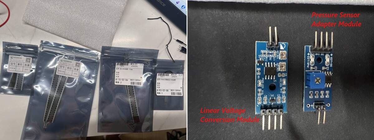
Pressure Sensor Materials Prepared
These parts were prepared for testing and comparison. They are not all final BOM items.
| Part | Model / Spec | Unit Price | Qty | Role |
|---|---|---|---|---|
| Strip FSR | 110mm strip pressure sensor | ¥18.5 / pc | 2 | Main sitting pressure test |
| Strip FSR | SF15-130, 130mm | ¥19.0 / pc | 2 | Wider area pressure comparison |
| Strip FSR | SF15-54, 54mm | ¥13.8 / pc | 2 | Smaller zone comparison |
| Round FSR | FSR402 / RFP602 | ¥10.8 / pc | 1 | Backup / local trigger |
| Pressure Sensor Adapter Module | Module A, one potentiometer, VCC / GND / DO / AO | ¥4.2 / pc | 1+ | Preferred module for strip FSR |
| Linear Voltage Conversion Module | Module B, two adjustment points, VCC / GND / DO / AO | ¥11.88 / pc | 1 | Comparison / backup module |
| XH2.54 Cable | XH2.54 / 3P / 30cm, 5 pcs per set | ¥1.98 / set | 2 sets | More stable connection |
| EPE Foam | 1m × 0.5m × 2mm, white EPE foam | ¥14.83 / sheet | 1 | Temporary pressure diffusion test layer |
I prepared multiple sensor types because the final cushion may need different sensing zones. The strip FSRs are the main candidates for wider area sensing. The FSR402 round sensor and shorter strip sensor are kept for comparison or local trigger testing.
Sensor Interface Module Comparison
I tested two different sensor interface modules. This became important because the same type of FSR sensor can behave differently depending on the module.
| Module | Name | Unit Price | Tested With | Signal Behavior | Current Judgment |
|---|---|---|---|---|---|
| Module A | Pressure Sensor Adapter Module | ¥4.2 / pc | 110mm strip FSR | No-pressure value was high; pressure made raw decrease | More suitable for strip FSR and cushion zone sensing |
| Module B | Linear Voltage Conversion Module | ¥11.88 / pc | FSR402 round sensor | No-pressure value was low; pressure made raw increase | Works, but better for comparison / local trigger |
Module A: Pressure Sensor Adapter Module
This module has one blue potentiometer and provides:
VCC
GND
DO
AO
I mainly used this module with the 110mm strip FSR. In my test, this module gave clearer analog readings through XIAO A0, so it is currently the preferred module for the main cushion sensing route.
Module B: Linear Voltage Conversion Module
This module has two adjustment points and also provides:
VCC
GND
DO
AO
I tested this module with the FSR402 round sensor. It also worked, but the signal direction was different. Without pressure, the raw value was low. When pressure was applied, the raw value increased and could reach saturation quickly.
The sensor and module must be documented together. Different modules can change the signal direction, reading range, and sensitivity.
Wiring
For both modules, I used the analog output pin for the test.
Sensor → sensor input side of the module

Module VCC → XIAO power pin
Module GND → XIAO GND
Module AO  → XIAO A0

Module DO → not used in this analog test
I used AO instead of DO because AO provides continuous analog readings. DO only gives a digital threshold output, which is less useful for pressure trend testing.
For modules that require 5V power, the AO voltage needs to be checked before connecting to XIAO A0. The XIAO ESP32-C3 is a 3.3V logic board, so the analog input should not receive 5V directly.
Reading Logic
In the Serial Monitor, I used several values to understand the sensor behavior.
| Value | Meaning |
|---|---|
raw |
Original ADC value read from XIAO A0 |
filtered |
Smoothed version of the raw value |
signedDiff |
filtered - baseline, used to see whether the signal goes up or down |
pressureAbs |
Absolute difference from baseline |
pressureValue |
Normalized 0–100 pressure trend value |
state |
Text label such as no pressure, light pressure, or strong pressure |
The raw value is not a body weight measurement. It is only an ADC reading. The value depends on the sensor, module, foam thickness, contact area, sensor position, and module sensitivity.
My body weight is around 58kg, but the Serial Monitor value does not mean 58kg. It only shows the pressure response under this specific sensor and foam setup.
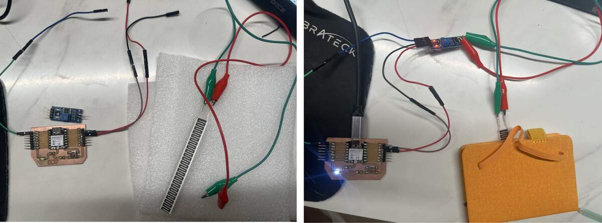
Test 02: 110mm Strip FSR + Pressure Sensor Adapter Module
In this test, I connected the 110mm strip FSR to the pressure sensor adapter module. The module AO pin was connected to XIAO A0.
I placed the strip sensor between two 2mm EPE foam layers and used a notebook / flat board to apply more even pressure. I also tested sitting on the foam structure directly.
This setup was closer to the final cushion structure than direct finger pressing.
Observation
The 110mm strip FSR worked clearly through the foam structure.
In the no-pressure state, the raw value was close to the baseline. When I sat on the foam structure, the raw value changed clearly, and the calculated pressure value increased strongly.
During a relatively still sitting position, the reading stayed in a small fluctuation range. It was also sensitive enough to detect small body movements while I was talking or shifting slightly.
Example Reading
| Condition | Raw / Filtered Behavior | Pressure Trend | State | Meaning |
|---|---|---|---|---|
| No pressure | Baseline / no-load value | Close to 0 | No pressure | Empty cushion |
| Notebook / flat pressure | Clear change from baseline | Strong increase | Strong / saturated | Pressure detected |
| Sitting on EPE foam | Stable high value | Strong sitting pressure | Sitting detected | Useful for sitting detection |
| Sitting still | Small fluctuation | Stable range | Stable sitting | Good for detecting stillness |
| Talking / slight body movement | Visible fluctuation | Sensitive movement response | Movement tendency | Useful later for motion logic |
Interpretation
The 110mm strip FSR is suitable for the final cushion because it covers a wider area than a round sensor. It is better for left / right / hip pressure zones and sitting-state detection.
However, the final system will need smoothing, threshold tuning, and calibration so the light does not react too much to small movement noise.
Test 03: FSR402 Round Sensor + Linear Voltage Conversion Module
In this test, I connected the FSR402 round thin-film pressure sensor to the linear voltage conversion module.
This setup also worked, but its signal behavior was different from the strip FSR test.
Without pressure, the raw value stayed around a low value, around 100–150. When pressure was applied, the raw value increased and could reach 4095.
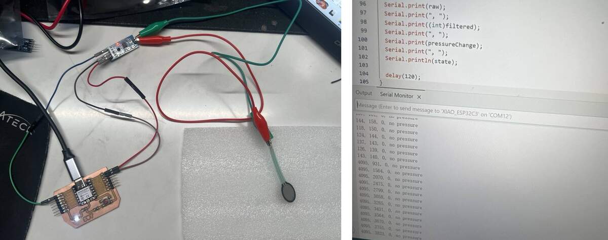
Observation
| Condition | Reading Behavior | Interpretation |
|---|---|---|
| No pressure | Raw around 100–150 | Stable no-pressure baseline |
| Pressed through foam | Raw increased quickly | Pressure detected |
| Strong local pressure | Raw could reach 4095 | Sensor / module saturated |
| Old mapping code | pressureChange stayed at 0 |
Code direction did not match this module |
Interpretation
The FSR402 round sensor is useful for local pressure detection. However, because it is a small single-point sensor, the pressure can be too concentrated and the signal can saturate quickly.
For my final cushion, this sensor is less suitable as the main pressure sensing method. It can be kept as a backup or local trigger sensor.
Test 04: 130mm and 54mm Strip FSR Preparation
I also prepared 130mm and 54mm strip pressure sensors.
The 130mm strip sensor may be useful for wider pressure zones because it covers a larger area than the 110mm sensor. It can be tested for the left / right / hip zones if I need more sensing coverage.
The 54mm strip sensor is smaller and may be useful for local zone testing or backup sensing, but it is less suitable for large-area sitting pressure detection.
The final choice between 110mm and 130mm will depend on the cushion size, sensor placement, and how much area I want each sensor zone to cover.
FSR Test Code
This code was used to compare different FSR sensors and interface modules. It reads the analog value from A0, calibrates a baseline, smooths the raw value, and maps the pressure change into a normalized value.
// Universal FSR module test for XIAO ESP32-C3
// Board: My designed XIAO ESP32-C3 board
// Module AO  -> XIAO A0
// Module GND -> XIAO GND
// Module DO is not used.
//
// Serial Monitor: 115200 baud
// Send "r" to recalibrate baseline when there is NO pressure.

const int SENSOR_PIN = A0;

int baseline = 0;
float filtered = 0;

int maxChange = 3800;
int noiseLimit = 10;

int lightLimit = 8;
int mediumLimit = 30;
int strongLimit = 70;

void calibrateBaseline() {
  Serial.println();
  Serial.println("=== Calibrating baseline ===");
  Serial.println("Remove all pressure from the sensor.");

  delay(1000);

  long sum = 0;
  for (int i = 0; i < 120; i++) {
    sum += analogRead(SENSOR_PIN);
    delay(10);
  }

  baseline = sum / 120;
  filtered = baseline;

  Serial.print("baseline = ");
  Serial.println(baseline);
  Serial.println("raw,filtered,signedDiff,pressureAbs,pressureValue,direction,state");
}

void setup() {
  Serial.begin(115200);
  delay(1200);

  analogReadResolution(12);
  calibrateBaseline();
}

void loop() {
  if (Serial.available()) {
    char c = Serial.read();
    if (c == 'r' || c == 'R') {
      calibrateBaseline();
    }
  }

  int raw = analogRead(SENSOR_PIN);

  filtered = filtered * 0.82 + raw * 0.18;

  int signedDiff = (int)filtered - baseline;
  int pressureAbs = abs(signedDiff);

  if (pressureAbs < noiseLimit) {
    pressureAbs = 0;
  }

  pressureAbs = constrain(pressureAbs, 0, maxChange);

  int pressureValue = map(pressureAbs, 0, maxChange, 0, 100);
  pressureValue = constrain(pressureValue, 0, 100);

  String direction;
  if (pressureAbs == 0) {
    direction = "none";
  } else if (signedDiff > 0) {
    direction = "positive";
  } else {
    direction = "reverse";
  }

  String state;
  if (pressureValue < lightLimit) {
    state = "no pressure";
  } else if (pressureValue < mediumLimit) {
    state = "light pressure";
  } else if (pressureValue < strongLimit) {
    state = "medium pressure";
  } else {
    state = "strong pressure";
  }

  Serial.print(raw);
  Serial.print(",");
  Serial.print((int)filtered);
  Serial.print(",");
  Serial.print(signedDiff);
  Serial.print(",");
  Serial.print(pressureAbs);
  Serial.print(",");
  Serial.print(pressureValue);
  Serial.print(",");
  Serial.print(direction);
  Serial.print(",");
  Serial.println(state);

  delay(100);
}
FSR Code Explanation
Baseline Calibration
The code first reads the sensor many times when there is no pressure and calculates a baseline.
baseline = sum / 120;
This is necessary because different sensors and modules start from different no-pressure values.
Software Smoothing
filtered = filtered * 0.82 + raw * 0.18;
This reduces small jumps in the raw analog reading.
Signal Direction
int signedDiff = (int)filtered - baseline;
This value shows whether the raw value goes up or down under pressure.
Unified Pressure Value
int pressureAbs = abs(signedDiff);
int pressureValue = map(pressureAbs, 0, maxChange, 0, 100);
Because different modules have different signal directions, I used the absolute difference from the baseline. This makes the final pressure value easier to compare.
Sensor and Module Comparison
| Test | Sensor | Module | Setup | Result | Meaning for Final |
|---|---|---|---|---|---|
| Test 01 | Copper foil contact sensor | Direct contact circuit | Conductive layers touched under pressure | Sensitive digital contact detection | Low-cost backup / reference |
| Test 02 | 110mm strip FSR | Pressure Sensor Adapter Module | Sensor placed between 2mm EPE foam layers | Clear sitting pressure response | Best current direction for main input |
| Test 03 | FSR402 round FSR | Linear Voltage Conversion Module | Round sensor tested under foam layer | Very sensitive, but easy to saturate | Useful as local trigger / backup |
| Test 04 | 130mm strip FSR | To be compared with adapter module | Longer strip for wider sensing area | Works as larger sensing option | Candidate for left / right / hip zone |
| Test 05 | 54mm strip FSR | To be compared | Shorter strip for smaller area | Backup comparison | Useful for small local zone |
Problems and Findings
1. Foam Changes the Reading
The pressure sensor does not behave the same when it is directly pressed by hand and when it is placed inside foam. Foam spreads the pressure and changes the contact area.
2. Single-Point Sensors Are Too Local
The FSR402 round sensor is sensitive, but its sensing area is small. In a cushion, body pressure is distributed over a larger area. A single-point sensor can miss pressure or saturate quickly depending on placement.
3. Long Strip Sensors Are More Suitable for the Cushion
The 110mm and 130mm strip FSR sensors cover a wider area. They are more suitable for detecting pressure trends across left, right, and hip zones.
4. Signal Direction Depends on the Module
Different modules produced different signal directions. One setup could output a high value without pressure and decrease under pressure, while another setup could output a low value without pressure and increase under pressure.
Because of this, the code should calibrate a baseline first and then calculate the change from that baseline, instead of assuming one fixed direction.
5. The Sensors Are Sensitive
The sensors were sensitive enough to detect pressure through foam layers. They could also detect small body movements while sitting. This is useful, but the final system will need smoothing, thresholds, and calibration so the light does not react too much to small noise.
Final Input Decision
After testing different pressure sensors and modules, I confirmed that all tested sensors can detect pressure changes.
For the final cushion, I will prioritize strip FSR sensors, especially the 110mm or 130mm type, for the main sensing zones. They are more suitable for area-based pressure detection because they cover more surface area.
The FSR402 round sensor is sensitive and useful, but it saturates easily under concentrated pressure. It is better as a local trigger or backup sensor.
The copper foil contact sensor will remain as a low-cost backup or reference contact detector.
The final input direction is:
- Main sensing: 110mm / 130mm strip FSR sensors
- Sensor zones: left side, right side, hip / center area
- Backup sensor: FSR402 round sensor or copper foil contact sensor
- Reading method: analog input through XIAO A0
- Physical structure: sensor layer tested first with 2mm EPE foam; final structure will use 60D high-resilience foam and a thin upper layer
- Future improvement: smoothing, threshold tuning, calibration, and web-based sensitivity adjustment
Updated Input Reflection
The copper foil test helped me understand digital contact input. It is simple and useful for detecting whether contact happens, but it cannot measure pressure intensity.
The commercial FSR tests helped me understand analog pressure input. FSR readings are more useful for my final cushion because they can show pressure trends, but they are also more sensitive to sensor shape, module type, foam structure, and calibration.
This means the final input system should not react directly to every raw value. It needs baseline calibration, smoothing, threshold tuning, and later web-based adjustment.
Next Steps
- Test the selected strip FSR under the final 60D high-resilience foam and thin upper foam layer.
- Decide the final position of the left, right, and hip sensing zones.
- Replace crocodile clips with more stable connectors or soldered wires.
- Connect the pressure input logic to the LED output system.
- Later connect the pressure input values to the web interface for sensitivity and threshold adjustment.