This week's directive is to add sensors to a microcontroller board that I have designed and read them. I decided to tackle two different types of inputs for my custom XIAO RP2350 board: a Sharp GP2Y0A41SK0F Infrared Distance Sensor and a custom-made piezoresistive fabric sensor using Velostat.
01. GROUP ASSIGNMENT
For the group assignment, we probed the analog levels and digital signals of an input device using an oscilloscope and a multimeter.
Since the Seeed Studio XIAO RP2350 is a very new microcontroller, the Arduino IDE does not recognize it by default. Before writing any code, I had to install the specific Board Manager Core. Here are the 7 steps I followed:
1 / 7
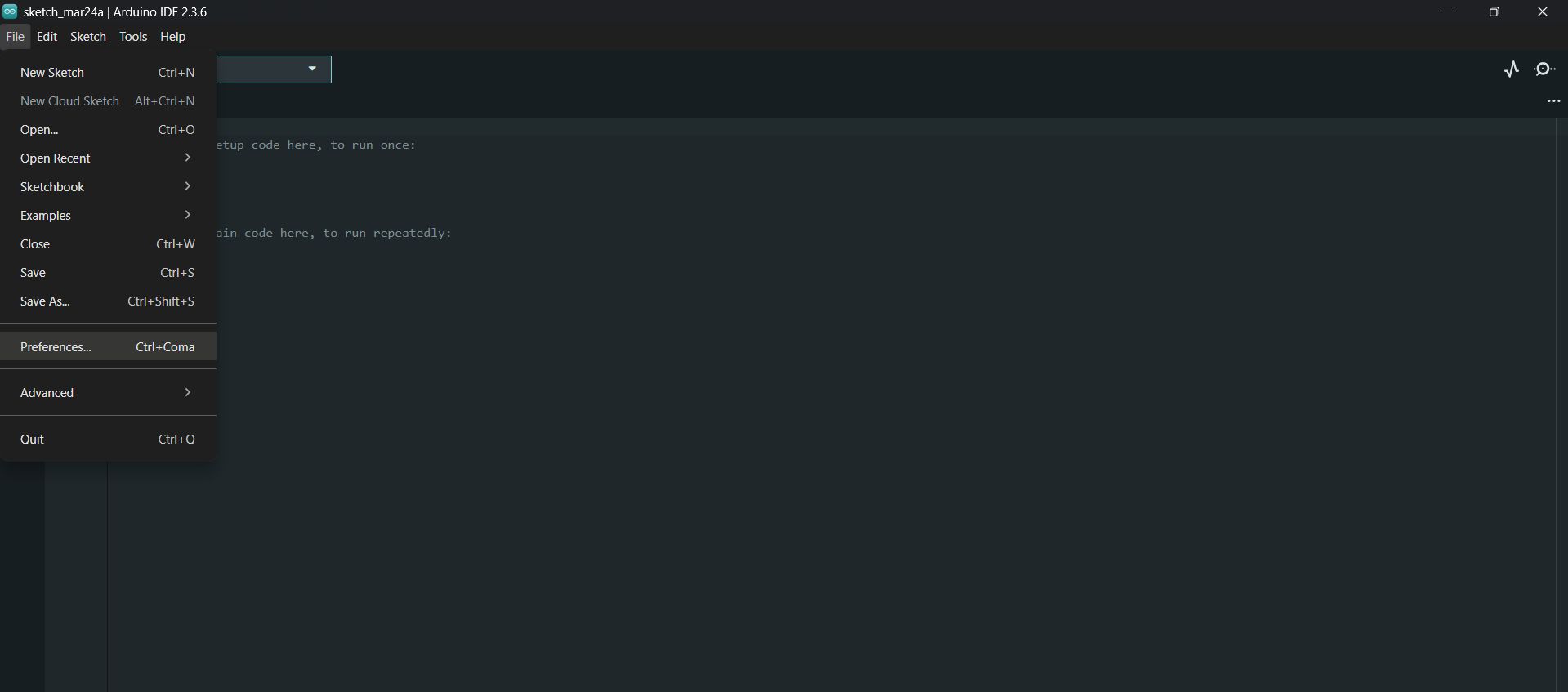
01. Opening File > Preferences to add the custom board URLs.
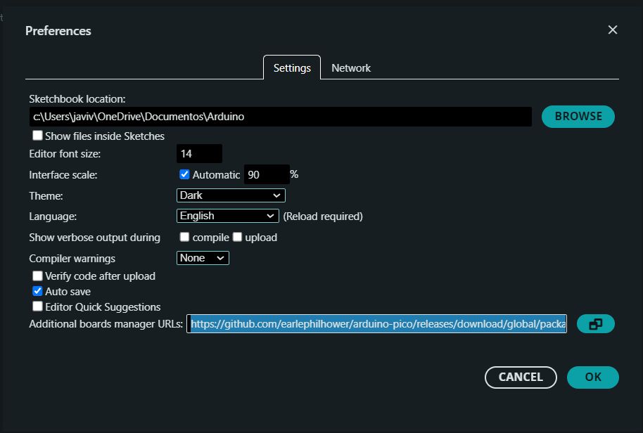
02. Pasting the Seeed Studio JSON URL into the Additional Boards Manager URLs. This is the link for the XIAO RP2350 core: https://github.com/Seeed-Studio/Arduino_Boards/raw/master/avr/package_seeed_index.json
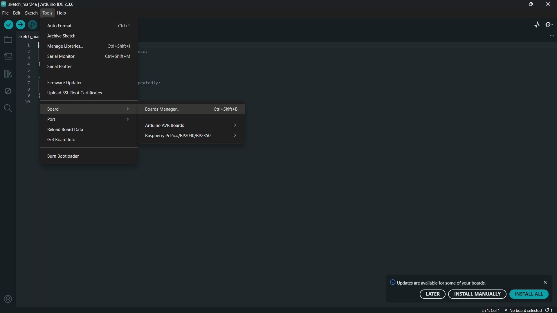
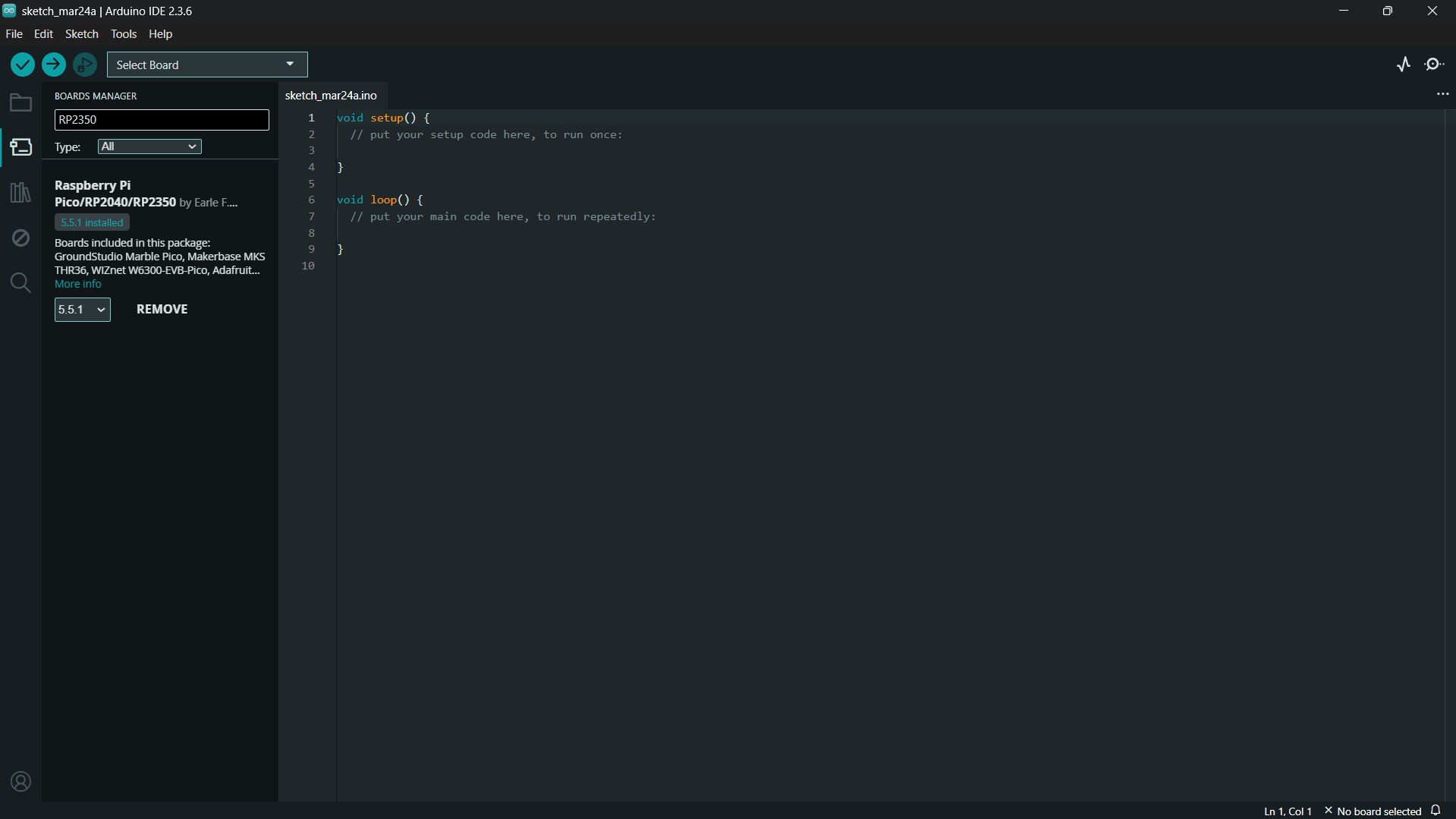
03. Opening the Boards Manager from the Tools menu.
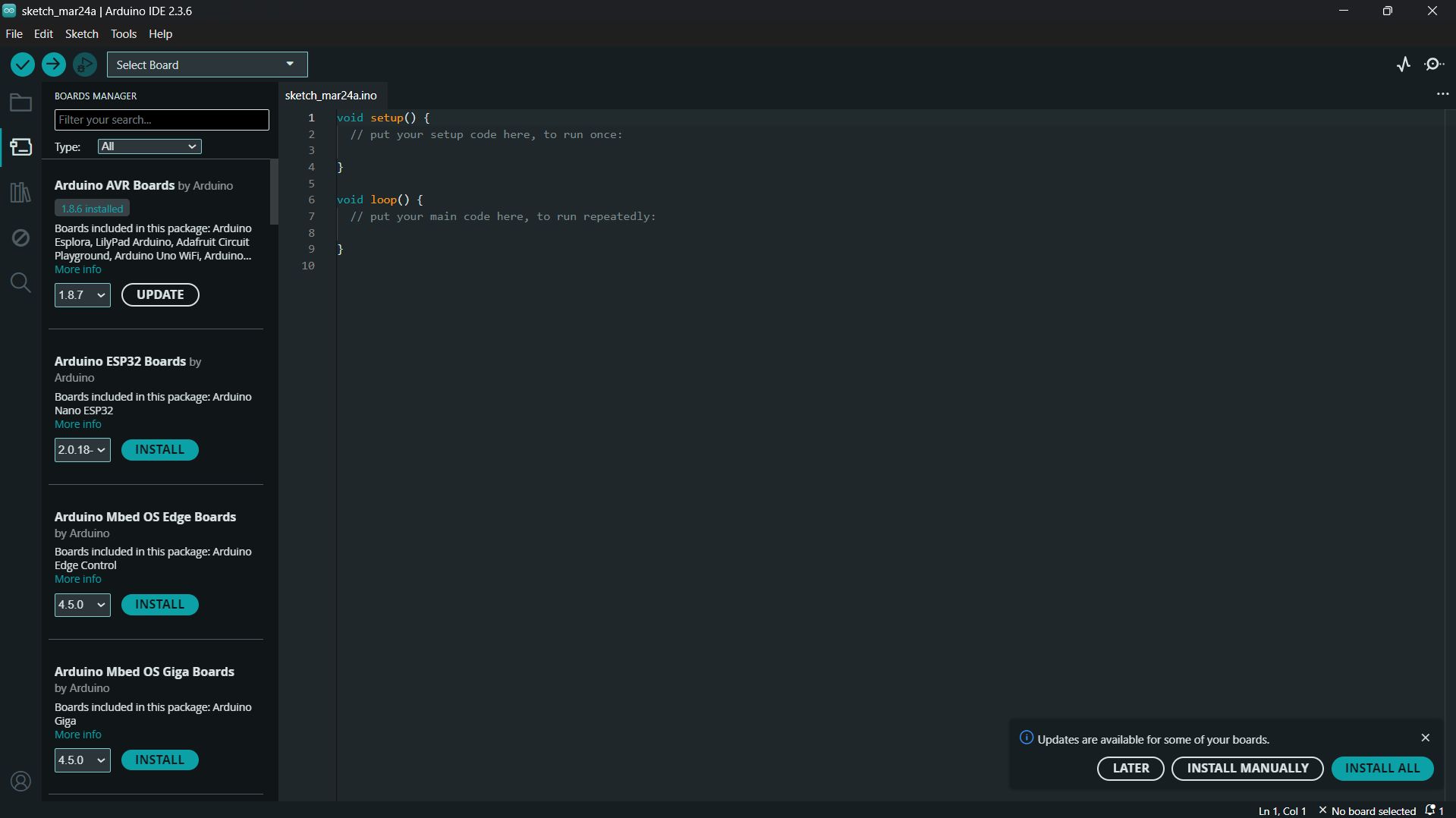
04. Searching for the "Raspberry Pi Pico/RP2040/RP2350" package.
05. Hitting the install button and letting the IDE download the core tools.
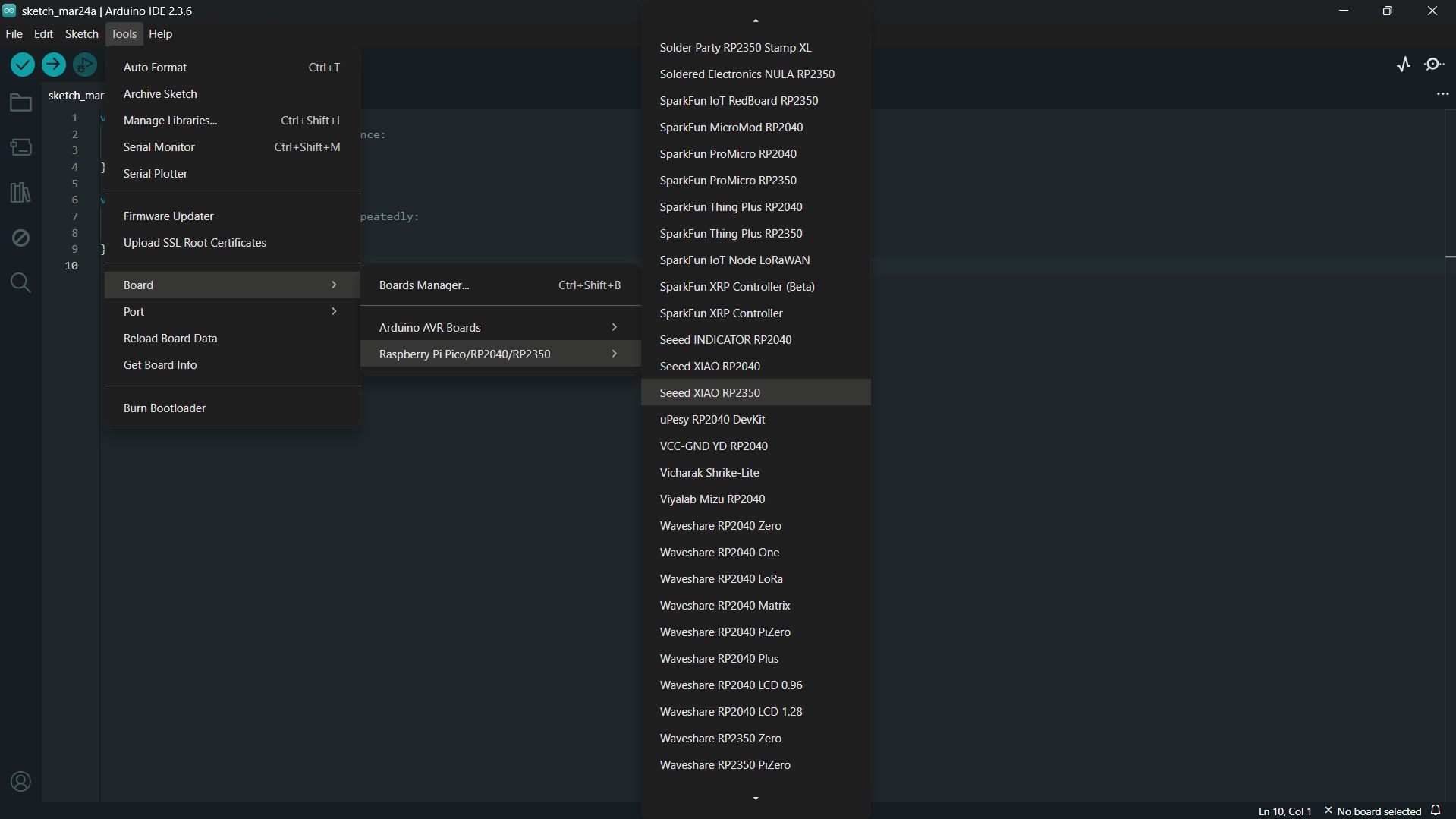
06. Finally, selecting the "Seeed Studio XIAO RP2350" board from the Tools menu to start programming!.
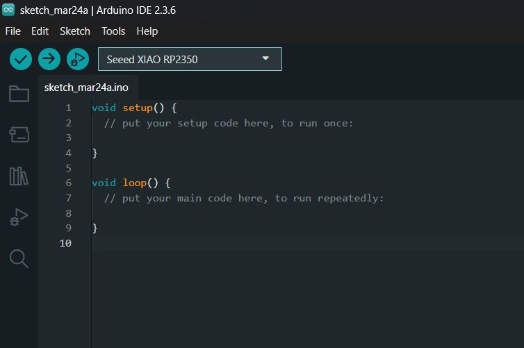
07. The board is now selected and ready for programming.
03. THE HARDWARE BASE (PCB V2.0)
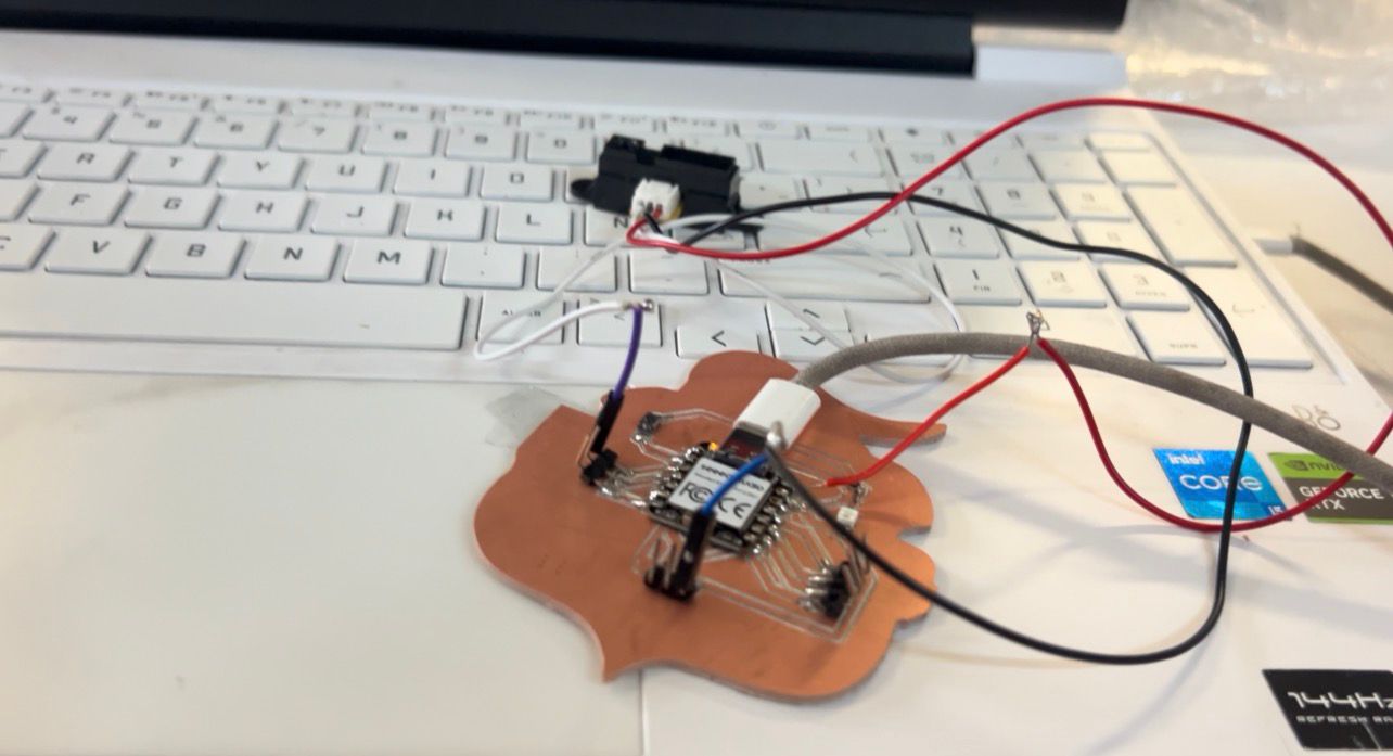
For this assignment, I am required to read a sensor using a board I designed myself. I am using the custom PCB I milled and soldered during Electronics Production week. At its core is the Seeed Studio XIAO RP2350. Since my design exposed 7 additional free pins via male headers, I had plenty of options. For these analog sensors, I decided to use the analog pin D2 (A2) to read the data, tapping into the available 5V and GND pads to power the modules.
My custom V2.0 board. Ready to receive analog signals.
04. TROUBLESHOOTING THE COM PORT
Before I could upload any code to read the sensors, I ran into a major roadblock: the Arduino IDE was not detecting the COM port of my XIAO RP2350. The board was powered on, but the computer couldn't communicate with it to upload the sketch. After some research, I found out this is a common issue with new RP2040/RP2350 chips.
⚙️ HOW TO ENTER BOOTLOADER MODE (XIAO RP2350)
To solve this, we need to force the XIAO into "Bootloader" mode. This bypasses the COM port issue and makes the microcontroller appear as a standard USB flash drive on your computer. Here is the exact physical button sequence required:
Press and HOLD the 'B' (Boot) button on the board.
While keeping 'B' held down, press the 'R' (Reset) button once.
Release the 'R' button.
Finally, release the 'B' button.
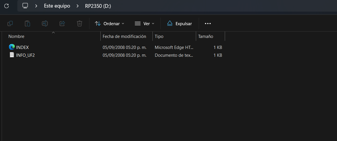
*Result: A new folder will pop up on your computer screen. Your board is now ready to receive the compiled `.uf2` file manually!
The solution involved manually compiling the code and flashing a binary file to upload the code to the Xiao without Arduino. Here is the step-by-step fix:
1 / 7
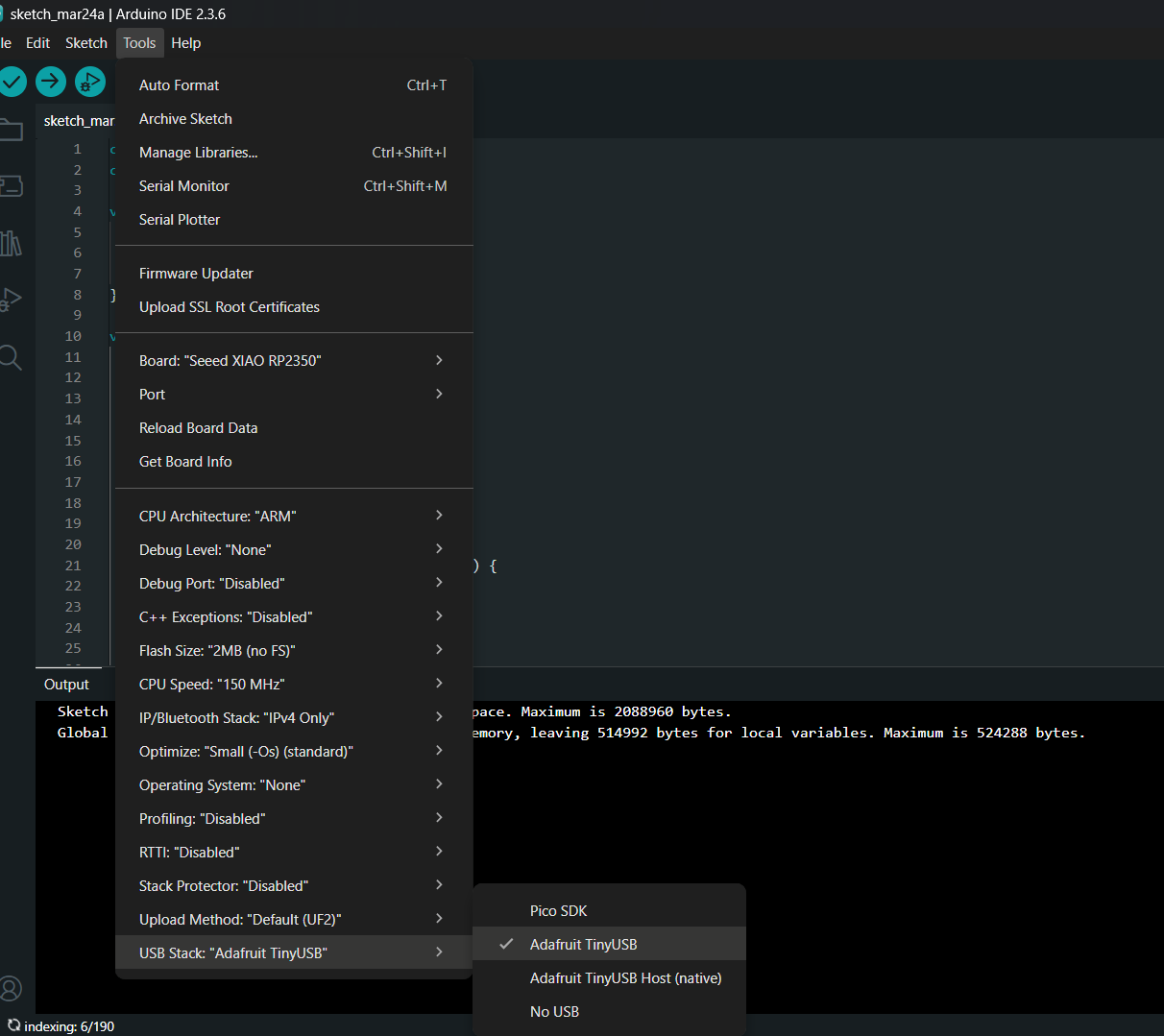
01. First, in the Tools menu, I changed the 'USB Stack' setting to 'Adafruit TinyUSB'. This is crucial for the USB communication to initialize properly on this chip.
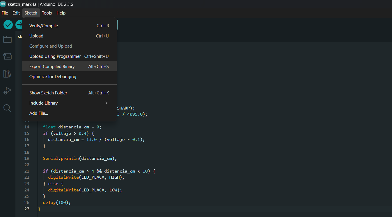
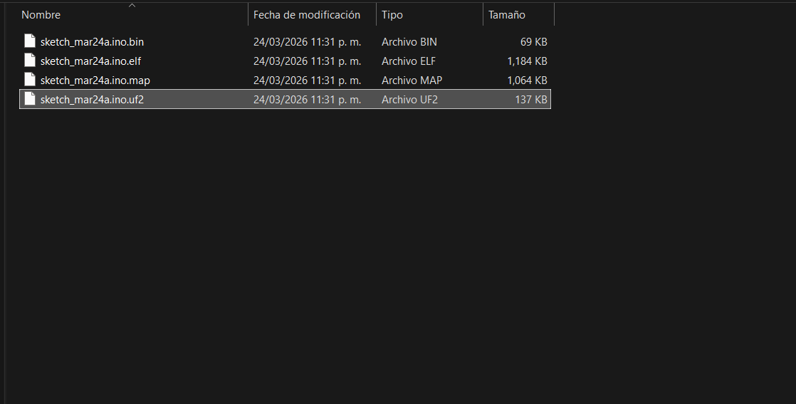
02. Next, instead of using the normal upload button, I went to Sketch > Export compiled Binary. This generates a .uf2 file inside the sketch folder.
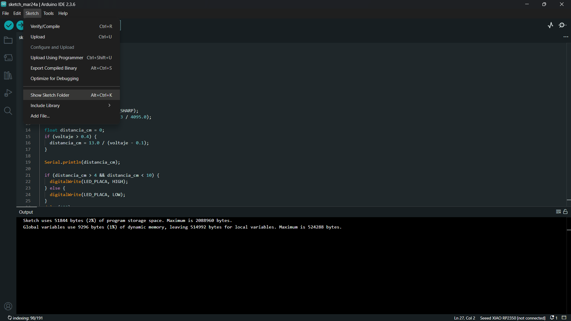
03. We need to look for the folder containing the .uf2 file. This is optional but if you don´t find it, you can get it clicking in "Show sketch folder"
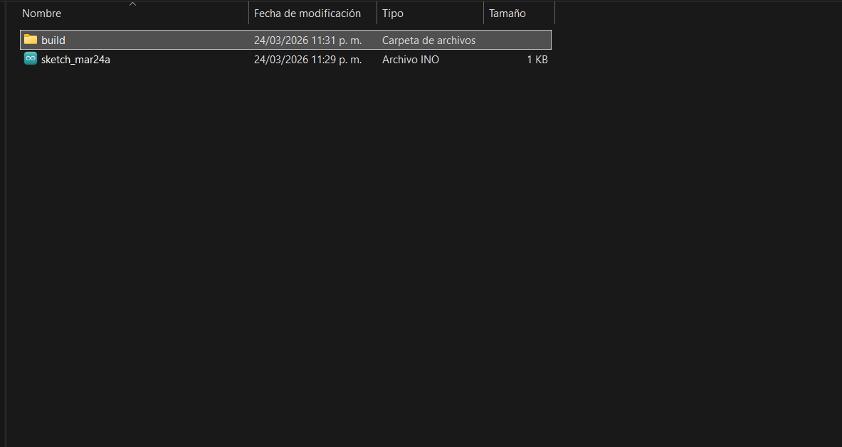
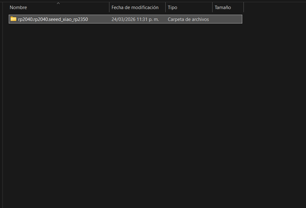
04. Inside the sketch folder, theres a folder named "built".
05. Inside the "built" folder, I found the file of the Xiao.
06. Finally I found the generated .uf2 file.
07. With the board in Bootloader mode (acting as a flash drive), I copied and dropped the generated .uf2 file into the XIAO drive. The board automatically rebooted, and the Xiao is now ready to use!
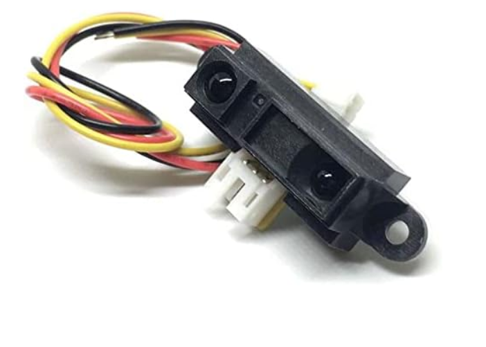
05. SENSOR 1: SHARP IR DISTANCE
I tested the Sharp GP2Y0A41SK0F. The sensor needs 5V to power on, but its output signal peaks at ~3.1V, which connects directly to the XIAO's 3.3V logic perfectly!
HOW IT WORKS: OPTICAL TRIANGULATION
Unlike ultrasonic sensors that measure the time it takes for a sound wave to bounce back, the Sharp IR sensor uses Optical Triangulation. It shoots a pulse of infrared light and measures the angle at which the light reflects back into its Position Sensitive Detector (PSD). Because it measures the angle rather than the strength of the light, it is not easily tricked by the color or reflectivity of the object!
Hero Test: The Serial Monitor displaying accurate distance in centimeters!
05. THE PIEZORESISTIVE FORCE (HOW IT WORKS)
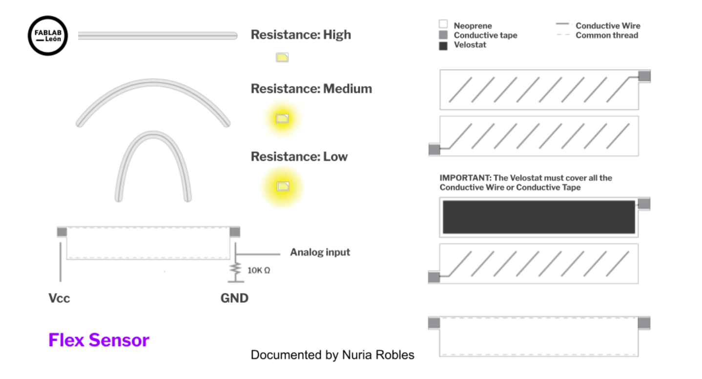
Before diving into programming, the mission required understanding the secret energy behind Velostat. The diagram below (from the excellent Fab Lab León documentation) decrypts the data.
1 / 2
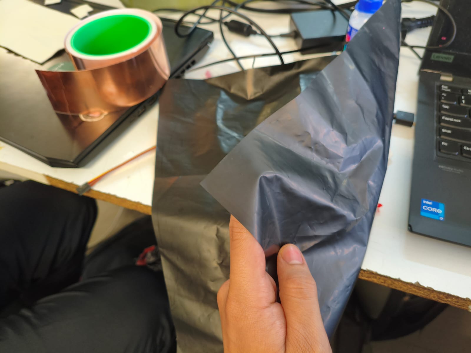
01. THE MATERIAL: This is Velostat—a pressure-sensitive conductive sheet (carbon-impregnated polyolefin). It's essentially a magical piezoresistive foil that acts as a super resistance variable.
02. THE LOGIC: The diagram reveals the logic. By placing Velostat between two conductive layers with a 10K ohm resistor connecting the 'Analog Input' to ground (creating a voltage divider), the machine reads pressure. High resistance (no touch) = low voltage drop. Low resistance (hard press) = high voltage drop, approaching Vcc.
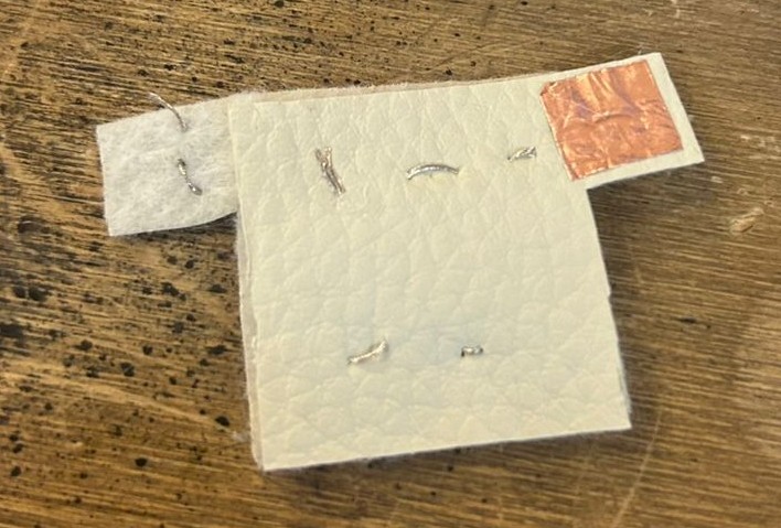
Our sewn t-shirt sensor operates on this exact principle. When pressure is applied to the Velostat layer between the conductive threads, the resistance between the conductors drops, allowing more voltage to pass to our analog input pin D2 (A2), which the machine converts into data.
06. SENSOR 2: VELOSTAT FABRIC SENSOR
For my second input, I designed an e-textile sensor using faux leather and Velostat. Velostat is a piezoresistive material whose electrical resistance decreases when compressed. I built a "shirt" structure with sewn contacts to create a complete circuit loop.
To connect this soft sensor to my rigid PCB, I used a modular approach: alligator clips paired with jumper wires. I clamped one alligator clip to the copper contact pad on the sensor and plugged its jumper end into the analog pin D2 (A2) on my board. The second alligator clip was attached to the conductive thread on the opposite side of the sensor, with its jumper connected to a GND pin.
By utilizing the XIAO's internal pull-up resistor (INPUT_PULLUP) in my code, I created a voltage divider without needing to solder any external resistors to my PCB. As pressure increases on the fabric, the resistance drops, and the analog value read by the ADC goes down.
Hero Test: Plotter visualizing pressure waves!
07. THE CODE VAULT
// CODE 1: SHARP IR
Understanding the Math: The Sharp IR sensor does NOT output a linear signal. To convert the raw voltage into actual centimeters, we must use an approximation formula derived from its datasheet curve. The formula distancia_cm = 13.0 / (voltaje - 0.1); is a standard algebraic fit used for the GP2Y0A41SK0F model to translate the non-linear voltage drop into a reliable distance reading (valid between 4cm and 30cm).
Week 9 is officially closed! Integrating both an infrared distance sensor and a custom analog e-textile sensor into a self-designed PCB proves that the hardware is fully operational.