◄ PAGE 09 PAGE 11 ►
WEEK #10

OUTPUT DEVICES

Giving movement to the goal and data to the screen: Servos, Motors, and OLEDs.

ALL ACCESS MISSION FILES (GITLAB REPO)

MISSION BRIEFING

This week's objective: Add an output device to a microcontroller board and program it to do something. I created a Universal Output Shield in the shape of the Red Hood logo to control my final project's mechanics, and additionally tackled the challenge of programming an OLED screen from scratch.

THE TARGET ACTUATOR

This is the Servo that I used for testing. It is an SG90, a common micro servo that can rotate approximately 180 degrees. It receives PWM signals from the microcontroller to control the angle of the servo horn.

00. GROUP ASSIGNMENT

For the group assignment, we probed the analog levels and digital signals of an output device using an oscilloscope and a multimeter.

📂 OPEN GROUP ASSIGNMENT

01. THE ACTUATORS

  • Servomotor SG90: For moving the precision targets in the goal.
  • DC Motor & TB67H451FNG Driver: For high-speed mechanical movement.
  • OLED Display 1.3" (SH1106): For visual feedback and score display.
  • LiPo Battery 7.4V: The main energy source.

02. MY WORKFLOW

I used Inkscape to design the PCB outline in the shape of the Red Hood logo. Then I exported the design to KiCad for layout and routing, and finally sent it to be manufactured.

03. THE PLOT TWIST: BODGE WIRE

During the mission, I discovered a missing trace between VCC and VREF. Every hero needs a backup plan, so I performed a surgical repair by soldering a Bodge Wire to restore power to the driver.

04. OUTPUT 1: SERVOMOTOR TEST

I used the Serial Monitor to control the SG90 servomotor. The code reads the angles that I type from the computer and moves the servo accordingly, demonstrating successful hardware-software integration.

Hero Test: Controlling the servo target via Serial Monitor!

05. OUTPUT 2: OLED DISPLAY

For my second output device, I decided to drive an SH1106 1.3" OLED display. Instead of taking the easy route and using a pre-built Arduino library (like Adafruit_GFX), I challenged myself to write a native C driver using the Raspberry Pi Pico SDK. It was a massive challenge, but writing my own ASCII font matrix and seeing the custom text appear on the screen pixel by pixel made it totally worth it!

Hero Test: The OLED display successfully running the native C code!

06. THE NATIVE I2C PROTOCOL

To make the OLED work without external libraries, I had to deeply understand the I2C Protocol and the SH1106 datasheet. Here is how the magic happens under the hood:

  • The I2C Bus: I initialized `i2c1` on the Pico at 400kHz, using GPIO 6 for SDA (Data) and GPIO 7 for SCL (Clock). The display listens at address 0x3C.
  • Control Bytes: Before sending data, the Pico must tell the screen what that data means. I learned to send a `0x00` byte before initialization commands (like turning the screen on), and a `0x40` byte before sending the actual pixel data to be drawn.
  • The Display Offset Hack: The SH1106 controller has enough RAM for a 132x64 screen, but the physical glass is only 128x64. This means the image gets shifted! I had to program a manual patch in C (col += 2;) to shift the cursor 2 pixels to the right, perfectly centering the image on the screen.

07. THE CODE VAULT

// 1. SERVOMOTOR CODE (ARDUINO IDE)
#include <Servo.h>

Servo miServo;  

const int pinSenal = D9; 

void setup() {
  Serial.begin(9600);
  miServo.attach(pinSenal);
  miServo.write(0);
  delay(2000); 
  
  Serial.println("========================================");
  Serial.println("READY TO WORK  ");
  Serial.println("========================================");
  Serial.println("Write a number from 0 to 180");
}

void loop() {
  if (Serial.available() > 0) {
    int angulo = Serial.parseInt();
    
    while (Serial.available() > 0) {
      Serial.read();
    }

    if (angulo >= 0 && angulo <= 180) {
      Serial.print("-> MOVING THE SERVO TO: ");
      Serial.print(angulo);
      Serial.println(" .");
      
      // Ejecutamos el movimiento
      miServo.write(angulo);
      
    } else {
      Serial.println("-> ¡Error! THE MECHANISM ONLY ACCEPTS NUMERS FROM 0 TO 180");
    }
  }
}
// 2. NATIVE OLED DRIVER (PICO C/C++ SDK)

This is the raw C code used to initialize the I2C bus, set up the display registers, load a custom ASCII font, and print my name pixel by pixel.

#include <stdio.h>
#include <string.h>
#include "pico/stdlib.h"
#include "hardware/i2c.h"
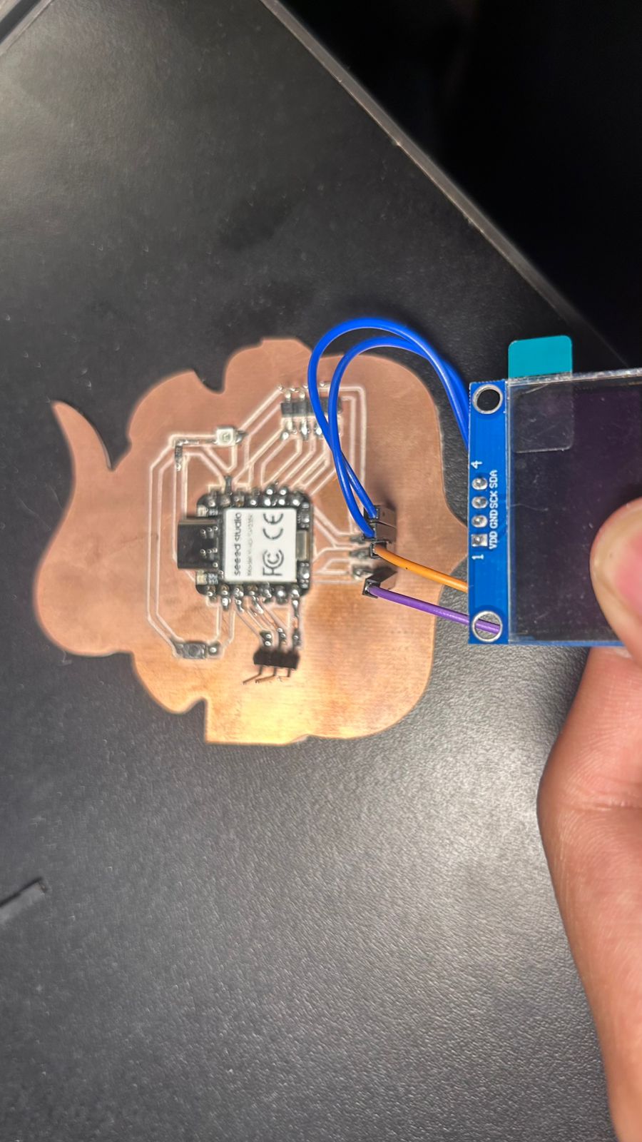
// Hardware Config
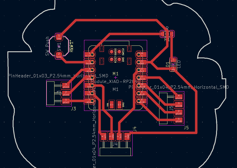
#define I2C_PORT i2c1
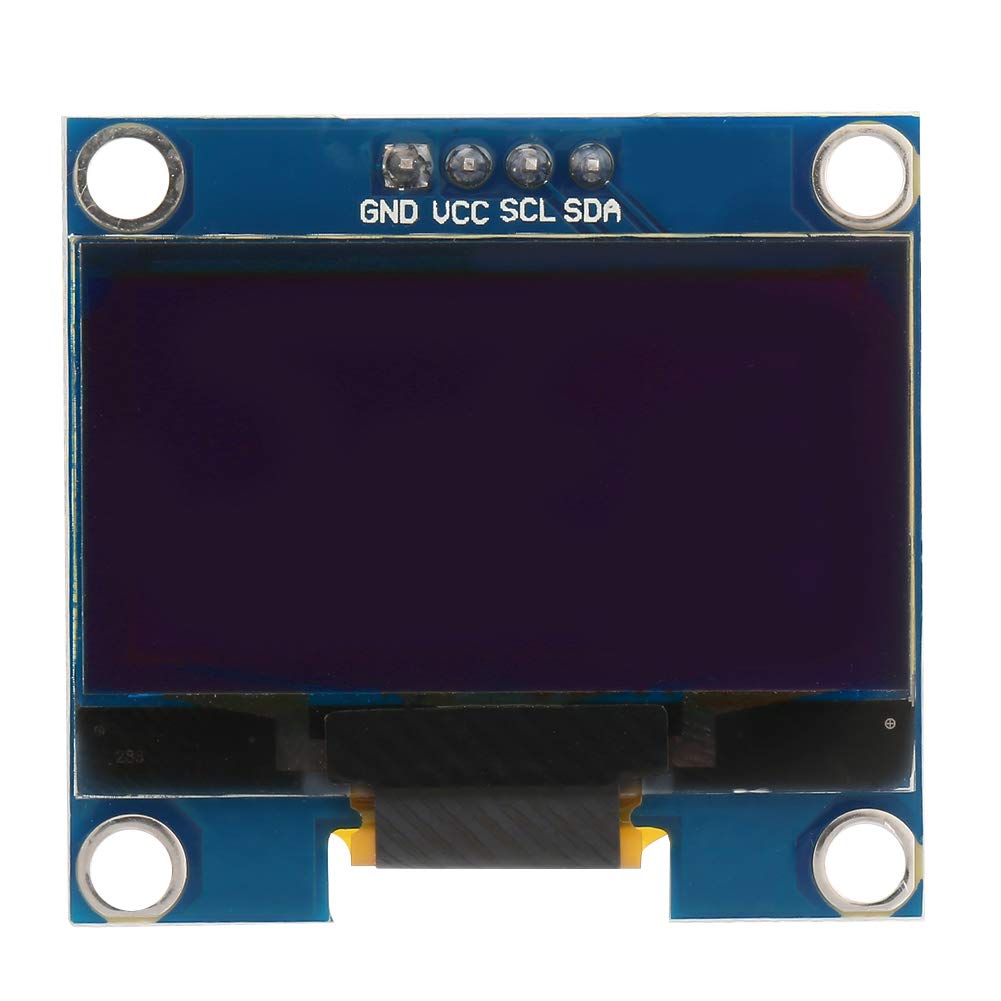
#define I2C_SDA 6
#define I2C_SCL 7
#define OLED_ADDR 0x3C

// ==========================================
// SH1106 NATIVE CONTROLLER
// ==========================================
void oled_cmd(uint8_t cmd) {
    uint8_t buf[2] = {0x00, cmd}; // 0x00 indicates Command
    i2c_write_blocking(I2C_PORT, OLED_ADDR, buf, 2, false);
}

void oled_init() {
    uint8_t cmds[] = {
        0xAE, 0xD5, 0x80, 0xA8, 0x3F, 0xD3, 0x00, 0x40,
        0x8D, 0x14, 0x20, 0x00, 0xA1, 0xC8, 0xDA, 0x12,
        0x81, 0xCF, 0xD9, 0xF1, 0xDB, 0x40, 0xA4, 0xA6, 0xAF
    };
    for (int i = 0; i < sizeof(cmds); i++) oled_cmd(cmds[i]);
}

void oled_set_cursor(uint8_t page, uint8_t col) {
    col += 2; // SH1106 Patch (Offset of 2 pixels)
    oled_cmd(0xB0 + page);
    oled_cmd(0x00 | (col & 0x0F));
    oled_cmd(0x10 | ((col >> 4) & 0x0F));
}

void oled_clear() {
    uint8_t vacio[128];
    memset(vacio, 0, 128);
    for (uint8_t page = 0; page < 8; page++) {
        oled_set_cursor(page, 0);
        uint8_t buf[129];
        buf[0] = 0x40; // 0x40 indicates Data
        memcpy(&buf[1], vacio, 128);
        i2c_write_blocking(I2C_PORT, OLED_ADDR, buf, 129, false);
    }
}

// ==========================================
// MICRO ASCII FONT 5x7 (Snippet)
// ==========================================
const uint8_t font_5x7[] = {
    0x00, 0x00, 0x00, 0x00, 0x00, // (Space, ASCII 32)
    0x00, 0x00, 0x5F, 0x00, 0x00, // !
    // ... [Font array omitted for brevity] ...
    0x00, 0x44, 0x7D, 0x40, 0x00, // i
    0x20, 0x40, 0x44, 0x3D, 0x00, // j
    0x38, 0x44, 0x44, 0x44, 0x38, // o
    0x1C, 0x20, 0x40, 0x20, 0x1C  // v
};

// ==========================================
// TEXT FUNCTIONS
// ==========================================
void oled_write_char(char c, uint8_t page, uint8_t col) {
    if (page > 7 || col > 122) return;
    int font_idx = (c - 32) * 5;
    if (font_idx < 0) font_idx = 0; 

    uint8_t buf[7]; 
    buf[0] = 0x40;  
    
    for (int i=0; i<5; i++) {
        buf[i+1] = font_5x7[font_idx + i];
    }
    buf[6] = 0x00; 

    oled_set_cursor(page, col);
    i2c_write_blocking(I2C_PORT, OLED_ADDR, buf, 7, false);
}

void oled_write_string(const char *str, uint8_t page, uint8_t col) {
    while (*str) {
        oled_write_char(*str, page, col);
        col += 6;
        str++;
        if (col > 122) {
            col = 0;
            page++;
            if (page > 7) break;
        }
    }
}

// ==========================================
// MAIN ROUTINE
// ==========================================
int main() {
    stdio_init_all();
    
    // Init I2C1 at 400kHz
    i2c_init(I2C_PORT, 400 * 1000);
    gpio_set_function(I2C_SDA, GPIO_FUNC_I2C);
    gpio_set_function(I2C_SCL, GPIO_FUNC_I2C);
    gpio_pull_up(I2C_SDA);
    gpio_pull_up(I2C_SCL);

    sleep_ms(500); 
    
    oled_init();    
    oled_clear();   
    
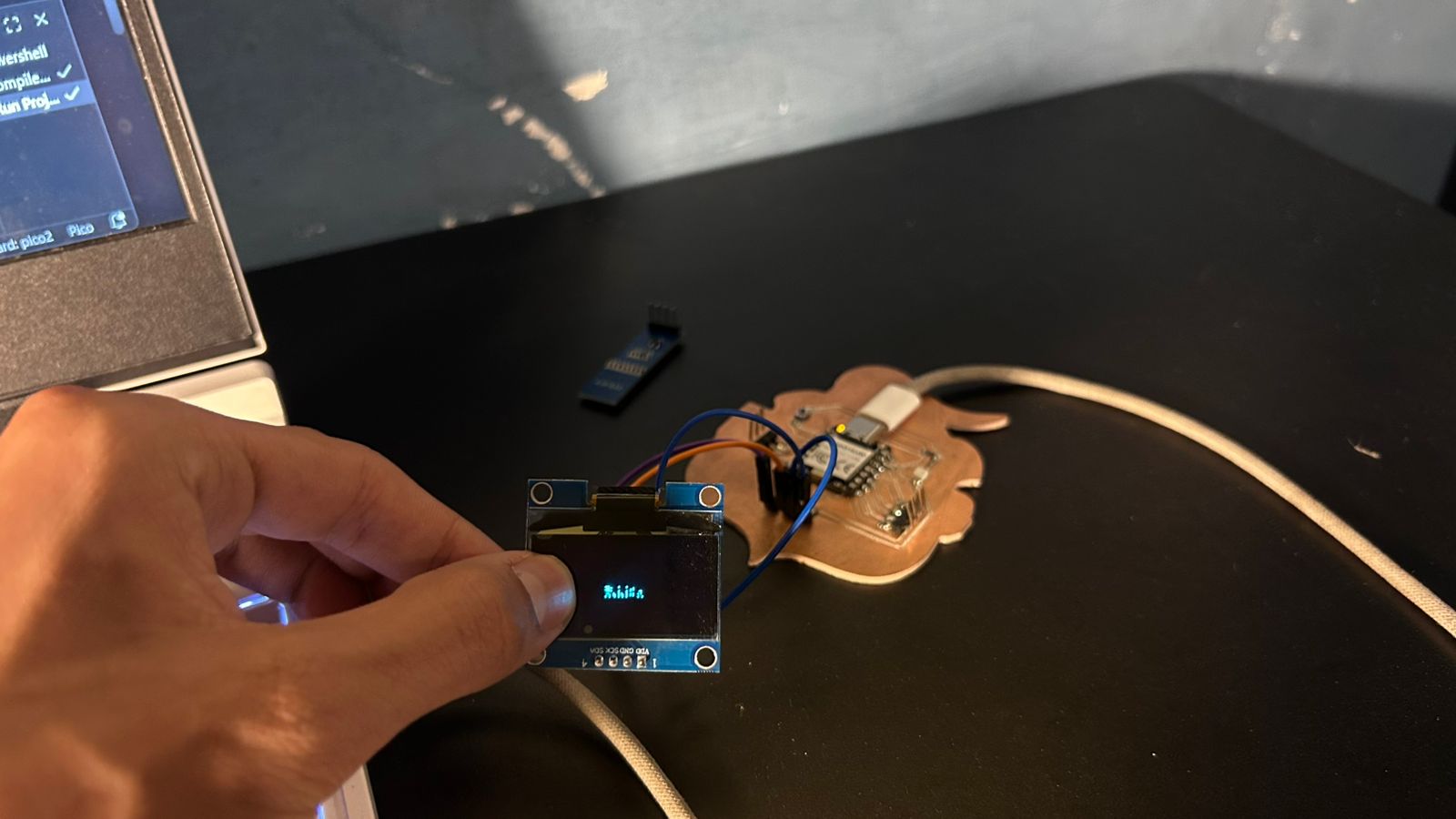
    // Tactical Mission: Write the message!
    oled_write_string("hello, i'm javi", 3, 19);

    while (true) {
        sleep_ms(1000); 
    }
    return 0;
}

MISSION ACCOMPLISHED

The targets are moving and the displays are rendering. Hardware and software fully integrated.