S.C.O.R.E.
MISSION IDENTITY
WHAT IT IS
S.C.O.R.E. (Smart Calculated Operations & Radar Engine) is a portable device that turns any regular soccer goal into a smart training system. You attach it to the goalposts, and it's ready. It automatically detects your shots, calculates kinetic speed through an invisible time-of-flight laser gate, and sends the data instantly to a custom Web App on your phone, mapping exactly where the ball entered.
Professional football tools are usually too expensive and hard to use for amateur players. Most people cannot measure their shot power or improve their accuracy with hard data. This project solves that problem by creating an accessible, industrial-grade tracking device that lets anyone track their progress just like the pros.
THE MOTIVATION
I have been passionate about football since I was a kid. Training alone can be frustrating without feedback. I often wonder: "How fast was that shot?" or "Did I hit the corner precisely?" By combining my passion for the sport with the digital fabrication skills learned in Fab Academy, I built a system to answer those questions.
TECHNICAL BLUEPRINT
To achieve portability and sub-millisecond precision, S.C.O.R.E. integrates the following components:
A. ELECTRONICS & IOT
- 2x XIAO ESP32C6: Powerful microcontrollers managing local edge-computing, ESP-NOW telemetry, and a Web Server.
- Custom PCBs: Fabricated in KiCad to route sensors and hardware logic protection.
- 8x Diffuse IR Sensors (3m): Industrial sensors creating the time-of-flight trap.
- 0.91" OLED I2C Display: Integrated directly on the master post for physical readouts.
B. POWER & MECHANICS
- 5V External Powerbanks: Portable autonomy for high-drain active sensors.
- 3D Printed Body (PLA): Impact-resistant cases designed in SolidWorks.
- Velcro Mounting System: Allows rapid deployment on any goalpost.
BILL OF MATERIALS (BOM)
One of the main goals of S.C.O.R.E. was to keep it accessible. By using standard components and digital fabrication, the total cost is drastically lower than commercial professional radars.
| Component | Qty | Approx. Cost (USD) |
|---|---|---|
| Seeed Studio XIAO ESP32C6 | 2 | $10.00 |
| E18 D80NK | 8 | $32.00 |
| SMD Components (SS14 Diodes) | 2 | $5.00 |
| 0.91" OLED Display I2C | 1 | $3.00 |
| 5V Portable Powerbanks | 2 | $20.00 |
| Velcro Straps & Fasteners | 1 Pack | $5.00 |
| TOTAL ESTIMATE: | $75.00 | |
R&D: SENSOR EVALUATION & PLOT TWIST
CRITICAL RESEARCH: BALL DETECTION
To catch a football traveling at 80+ km/h, optical hardware needs an insanely fast response time. Standard sensors lacked the range, but I discovered a breakthrough.
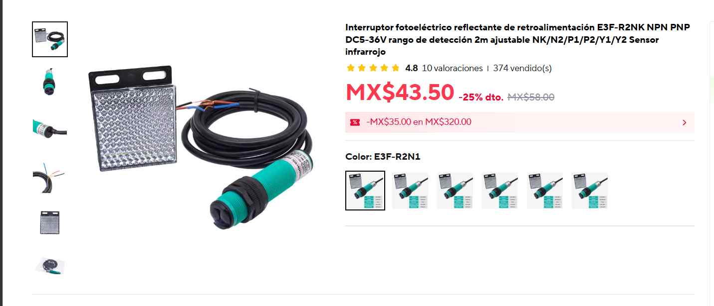
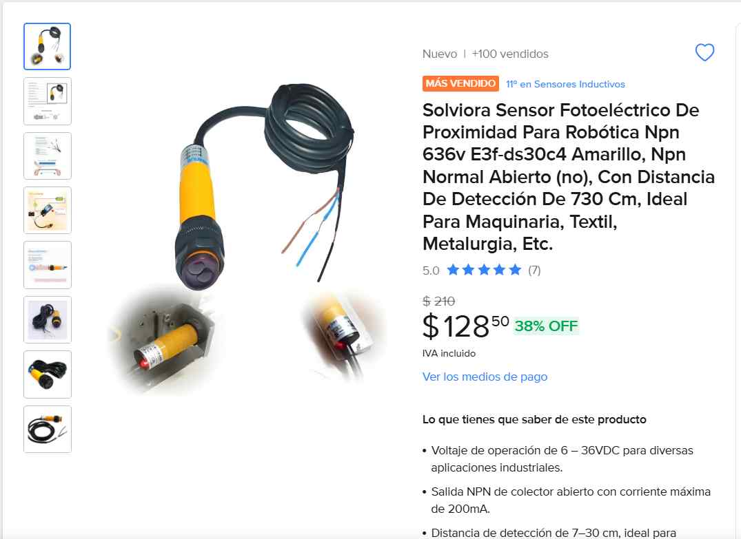
1. Solviora E3F-DS30C4 (Standard)
- Response Time: 1 ms (Excellent)
- Range: 3 - 80 cm
- Verdict: REJECTED
Analysis: While the 1ms response time was perfect for high-speed tracking, its maximum range of 30 cm is a critical failure point. A football passing through the center of the net would go undetected.
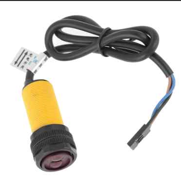
2. E3F 3-Meter Diffuse Variant
- Response Time: 1 ms (Instant Reaction)
- Range: Up to 3 Meters (300 cm)
- Verdict: SELECTED
Analysis: THE PLOT TWIST. I discovered an upgraded industrial variant of the sensor that extends the diffuse range to a massive 3 meters. This eliminates the need to align complex reflector plates across the goal, while keeping the crucial 1ms reaction time to prevent blind spots.
INPUTS & OUTPUTS
INPUT DEVICES: THE SENSORY NERVES
The system uses eight E18-D80NK Infrared Distance Sensors acting as the primary inputs. These sensors work on the "Beam Breaking" principle. They continuously emit an IR light beam. When a physical object (the football) enters their line of sight, the light reflects back into the receiver. This triggers an immediate hardware interrupt, sending a digital LOW signal directly to the XIAO ESP32-C6.
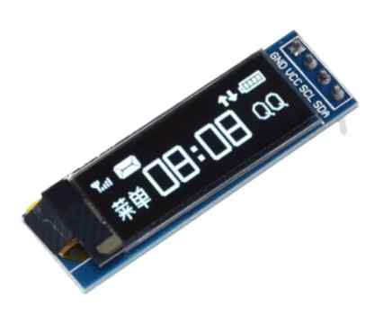
OUTPUT DEVICES: THE VISUAL FEEDBACK
While the main output is the mobile Web Dashboard, the system also features local hardware feedback. A 0.91" I2C OLED Display acts as the primary physical output. Connected to the Master Board, this screen provides instant on-the-field metrics, displaying the calculated speed of the ball immediately after an impact is registered without needing to look at a phone.
SYSTEM ARCHITECTURE & COMMS
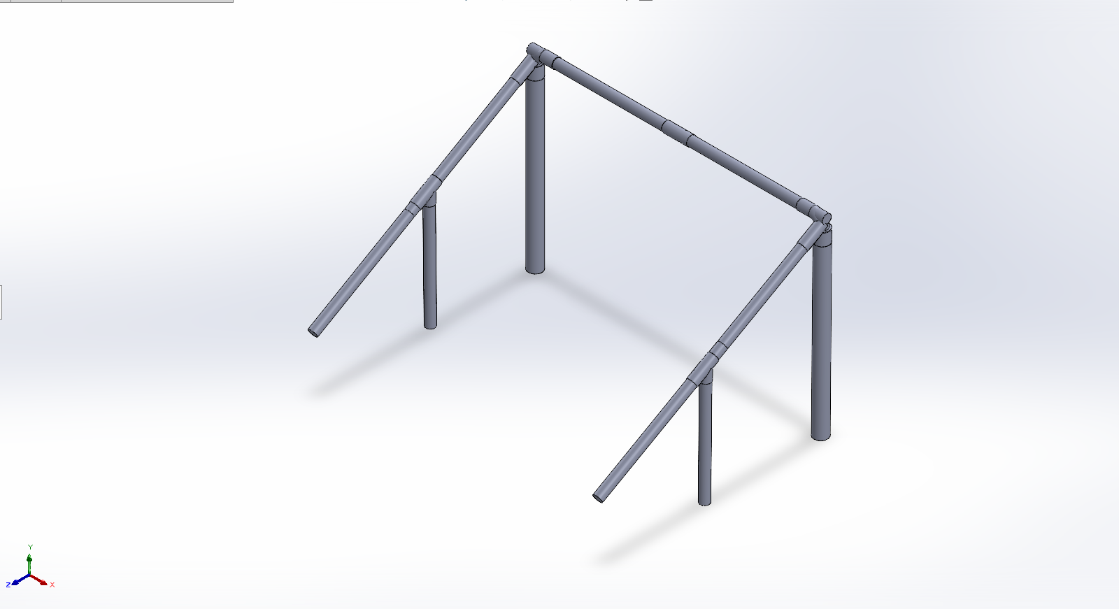
To track the entire goal without running wires across the 1.6-meter crossbar (which would inevitably break from ball impacts), the system relies on a Wireless Dual-Node Topology. Each post is entirely independent in terms of power, utilizing its own dedicated 5V Powerbank to drive the high-drain active sensors.
PHYSICAL DISTRIBUTION
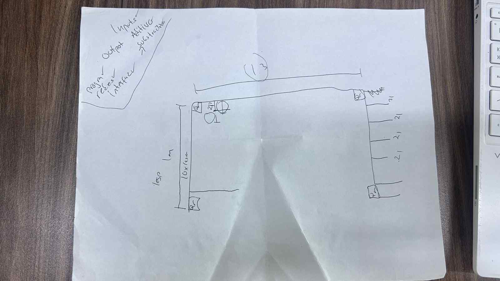
Fig 2. Sensor distribution along both vertical posts to detect ball crossing position and speed.
PROGRAMMING LOGIC
1. THE SPEED TRAP MATH
The core logic relies on classical physics kinematics. The goal structure holds a front sensor and a back sensor perfectly parallel. The physical depth separating them is exactly 30 cm (0.3 meters).
- When the ball breaks the front sensor's beam, a hardware interrupt is triggered, and the code starts a high-precision `micros()` timer.
- When the ball travels and breaks the back sensor's beam, the code stops the timer and calculates the total elapsed time.
- Using the fixed 30 cm distance, the MCU derives the velocity using the formula: $v = \frac{d}{t}$. Finally, the output is converted to km/h to be displayed to the user.
2. HARDWARE LOGIC: ACTIVE-LOW
A major learning curve involved understanding industrial NPN logic. The sensors operate as Normally Closed (NC). The MCU pin reads HIGH when idle. When the infrared beam is reflected back by a passing ball, the circuit connects to Ground, pulling the logic pin to LOW. The C++ logic had to be inverted to register `LOW` as a positive hit.
3. DEFEATING THE "DISCO EFFECT"
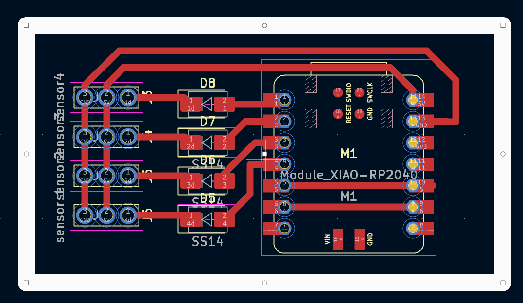
PCB FABRICATION
DESIGNING & MILLING THE BOARDS
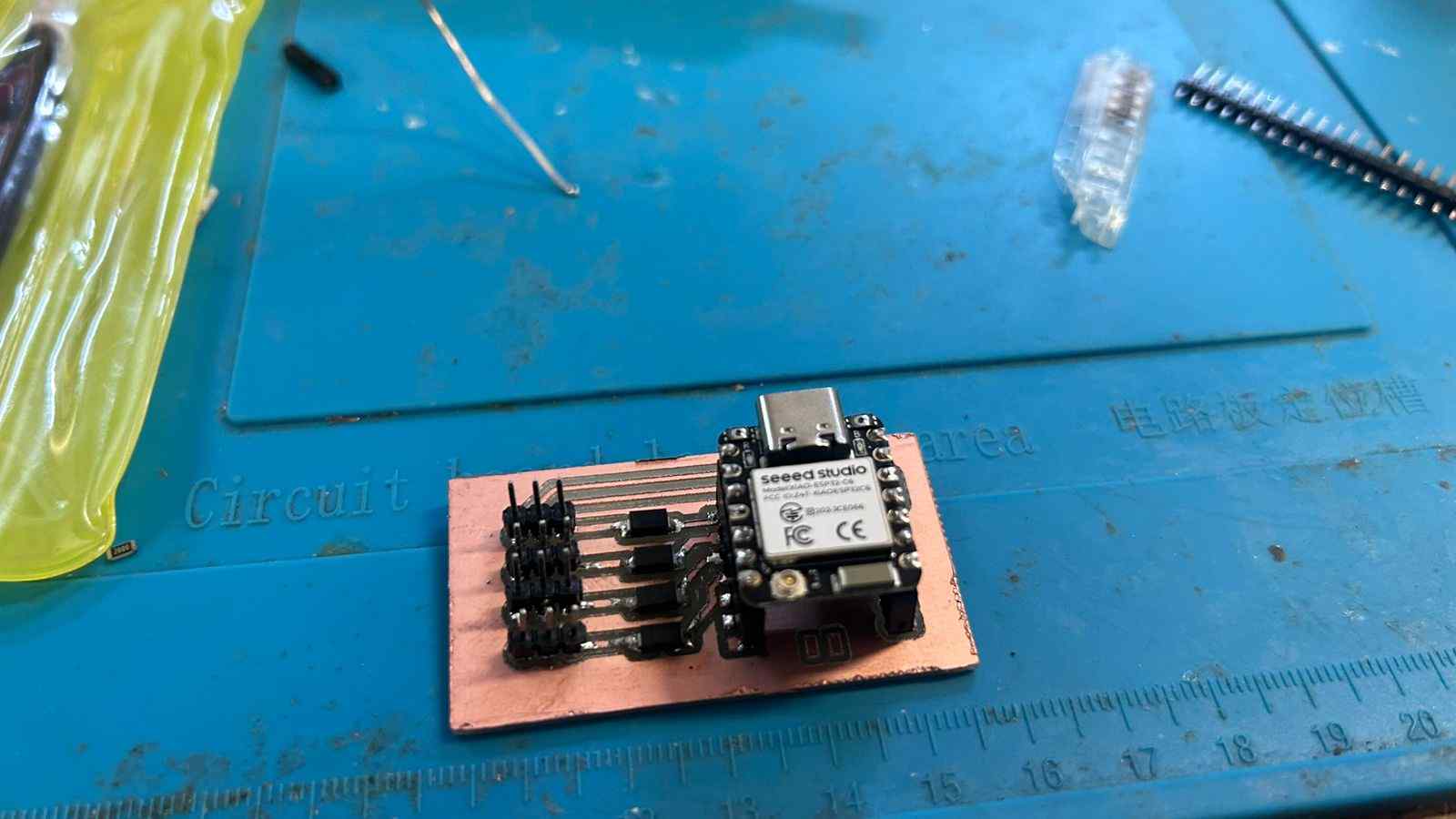
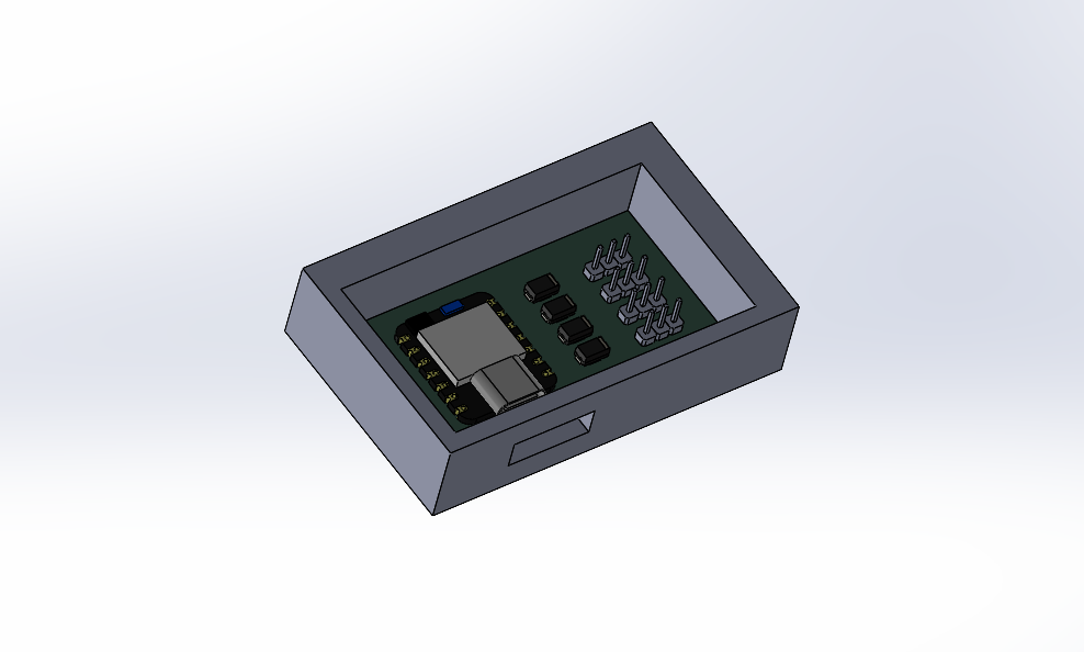
The electronic heart of S.C.O.R.E. consists of two custom PCBs (Master and Slave) designed in KiCad. These boards serve to break out the pins of the XIAO ESP32-C6, manage power distribution, and house the SS14 hardware protection diodes.
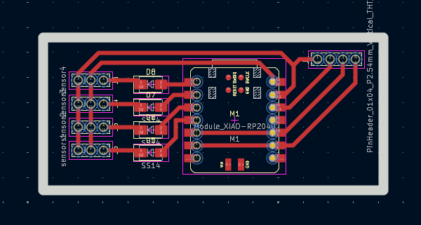
After the CNC milling was complete, the SMD components and pin headers were hand-soldered to ensure robust connections capable of withstanding the vibrations of a soccer ball impact on the frame.
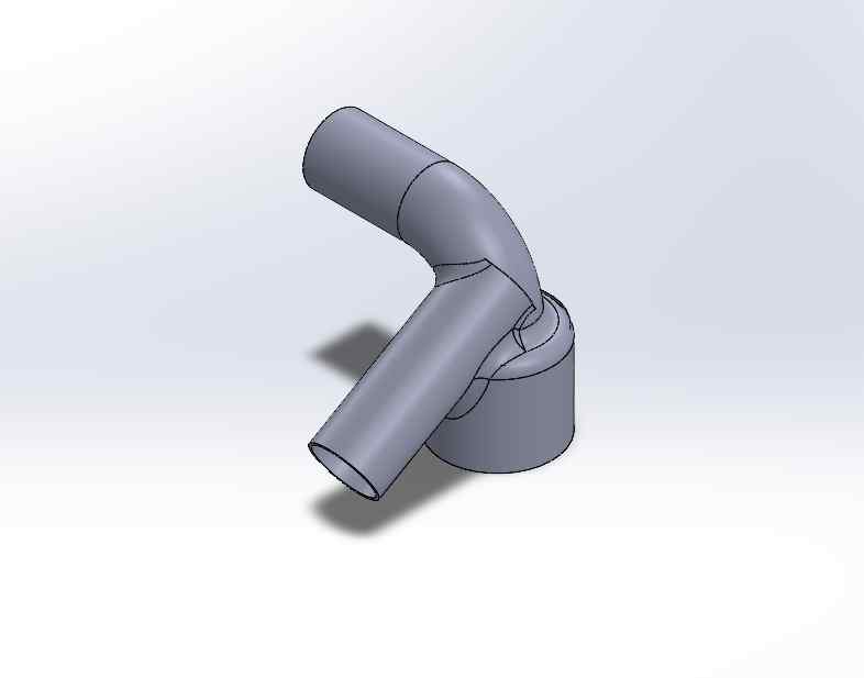
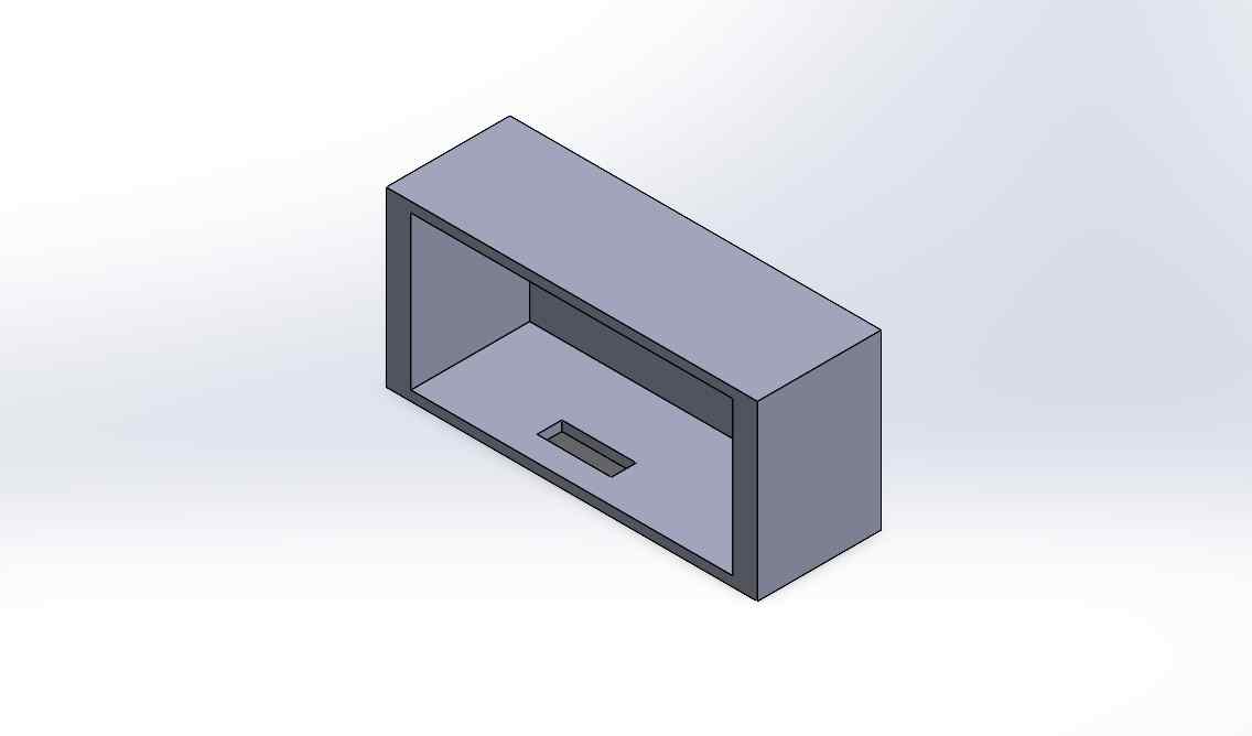
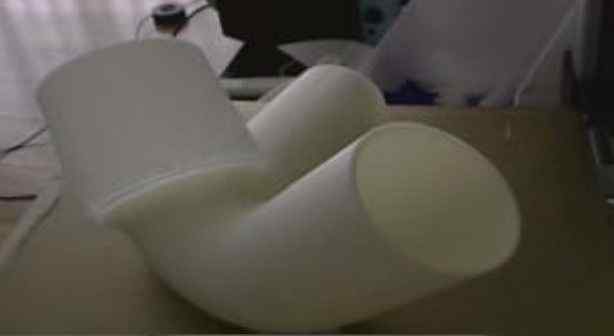
ADDITIVE MFG (3D PRINTING)
To achieve a perfect fit and protect the electronics, all enclosures and frame joints were modeled in SolidWorks and produced using Additive Manufacturing (3D Printing). The casings hold the sensors perfectly parallel to ensure the Time-of-Flight distance remains exactly 30 cm.
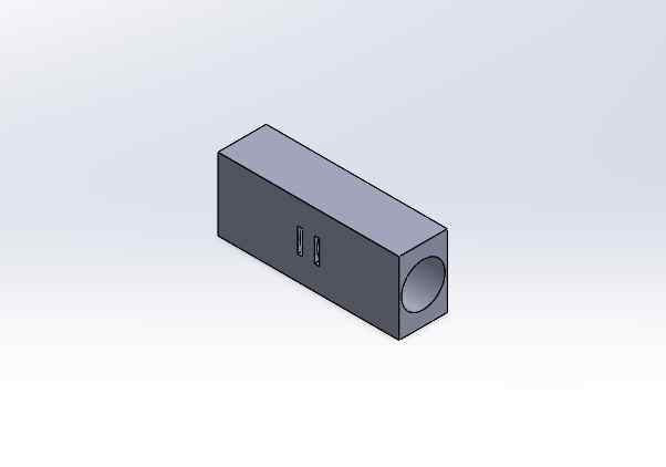

THE PRINTING PROCESS
All enclosures were printed using standard PLA filament. Parameters were optimized for strength: thick walls (1.2mm minimum) and high infill (30% cubic) to withstand stray ball impacts.
SUBTRACTIVE MFG (DECORATION)
BRANDING & AESTHETICS
To give the prototype a finished, commercial look, I utilized subtractive manufacturing (Vinyl Cutting) to create custom decals for the goalposts. A silhouette of CR7 was vectorized and cut on the plotter to decorate the PVC structure.
INTERFACE PROGRAMMING
THE MOBILE DASHBOARD
The data generated by S.C.O.R.E. is useless if the player can't see it. The Master board is programmed to create its own Wi-Fi Access Point (Local Server). By connecting a smartphone to this network, the player accesses a custom HTML/JS interface completely hosted on the microcontroller.
THE HARDWARE SHIELD: LOGIC DIODES
Using industrial NPN sensors created an electrical hazard. The sensors can output higher voltages, but the XIAO ESP32C6 operates strictly at 3.3V. High voltage on the data pins would fry the board instantly.
- The diode is placed with its cathode (grey line) pointing toward the sensor's signal wire.
- Idle (No Ball): The diode blocks higher voltages from returning to the board. The XIAO pin remains safely HIGH via its internal 3.3V pull-up.
- Triggered (Ball Detected): The NPN sensor connects the line to Ground (0V). The diode "opens", pulling the XIAO pin to LOW, registering a hit without voltage exposure.
FULL DEMONSTRATION
The culmination of the S.C.O.R.E. project. Below are the key video logs documenting the physical assembly on the goal, the raw sensor calibration tests, and the final working prototype.
FUTURE UPGRADES
The S.C.O.R.E. prototype fulfills the initial requirements of providing accessible, local telemetry for football training. However, the architecture is designed to be scalable. Future developments include:
- Integrated LiPo Battery Management: Replacing the external powerbanks with internally managed 18650 batteries and TP4056 charging circuits.
- Cloud Database Logging: Adding an MQTT bridge to allow players to save their historical data and track their speed improvements over months of training.
- Advanced Gamification: Programming "Target Practice" modes where the OLED screen tells the player which zone to hit, scoring them based on accuracy and speed.
STRATEGIC TIMELINE
Roadmap aligned with the Fab Academy 2026 Official Schedule. Click on any phase to view the full weekly documentation.
-
WEEK 1 (JAN 21)
Project Management
Defining the concept, sketching the initial idea, and setting up the documentation website (Git & HTML).
-
WEEK 2 (JAN 28)
Computer-Aided Design
Creating the first 2D and 3D representations of the goal structure using SolidWorks.
-
WEEKS 6-8 (FEB-MAR)
Electronics Design & Production
Designing the custom PCB in KiCad (Week 6) and fabricating it (Week 8) to house the ESP32 and power management.
-
WEEK 11 (APR 01)
Networking & Communications
Programming the ESP32s to communicate wirelessly via ESP-NOW and Wi-Fi Access Point.
-
WEEK 14 (APR 29)
Interface Programming
Developing the visual Asynchronous Web Dashboard where the player sees their speed and accuracy stats.
-
WEEKS 15-17 (MAY)
System Integration & Development
Final assembly, 3D printing enclosure, cable management, field testing, and recording the presentation video.