Making devices talk: Architecture, Nodes, I2C, and Wireless Protocols.
00. GROUP ASSIGNMENT
What I learned from the group assignment: We probed the analog levels and digital signals of an output device using an oscilloscope and a multimeter. My main takeaway was visualizing the difference between a constant voltage reading on a multimeter versus seeing the actual PWM square waves and voltage spikes on the oscilloscope when a motor is running. This taught me why calculating power limits is so critical before connecting outputs.
This week's objective is to establish communication between at least two processors or devices. I tackled both wired and wireless protocols using the powerful ESP32-C6 microcontroller. The mission involves mapping the network architecture, wiring an I2C bus to extract data from a sensor and display it on an OLED, and setting up an ESP-NOW peer-to-peer connection for my Final Project.
01. NETWORK ARCHITECTURE & NODES
To understand how the communication works, we must define the Network Topology. A valid critique during my evaluation was: "It seems you only have one node PCB, and your computer... add at least another node."
To solve this, I expanded my network to include distinct microcontrollers and devices talking to each other.
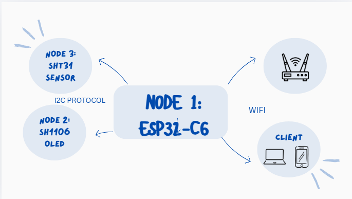
Node 1 (The Master MCU): My custom ESP32-C6 board. It acts as the brain, polling data and hosting the wireless server.
Node 2 (Wired Slave MCU): The built-in controller inside the SH1106 OLED Display. It receives rendering commands via I2C.
Node 3 (Wired Sensor Node): The SHT31 IC. It calculates temperature and humidity and sends the raw bytes via I2C.
Node 4 (Wireless Client): A Smartphone connecting to the ESP32-C6's local IP address to read the live data stream.
Architecture Diagram: The flow of data across multiple nodes in the local and wireless network.
02. PROTOCOL ANALYSIS: WHY MQTT?
During the development of the wireless communication, I evaluated different protocols. While I ultimately used an HTTP Web Server for quick visualization in this specific documentation, MQTT (Message Queuing Telemetry Transport) is the superior protocol for remote sensor networks. Here is the technical justification:
1. Packets & Overhead
HTTP is a "heavy" protocol. Every time my ESP32 requests or sends data via HTTP, it must send massive textual headers (Cookies, User-Agent, Accept, etc.), often exceeding 500 bytes just to send a 2-byte sensor reading. MQTT, on the other hand, has a fixed, ultra-lightweight header of only 2 Bytes.
2. Speed & Latency
Because MQTT packets are tiny, the transmission speed is significantly faster, and it requires far less bandwidth. For a project where I need real-time target detection, the latency of opening and closing TCP connections for every HTTP request is unacceptable. MQTT keeps a persistent connection open to a Broker.
3. Publish / Subscribe Architecture
HTTP uses a strict Request/Response model (the client must ask for data). MQTT uses a Pub/Sub model. My ESP32 simply "Publishes" data to a topic, and any node "Subscribed" to that topic receives the data instantly.
03. WIRING DIAGRAMS
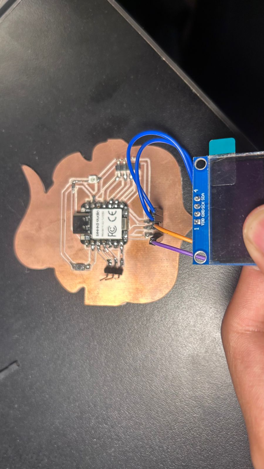
Before jumping into the code, here is the exact wiring diagram mapping the physical connections between the nodes. Both the OLED and the SHT31 sensor share the exact same I2C bus (SDA and SCL pins) without interfering with each other because they have different hardware addresses.
Wiring Diagram: Routing the 3.3V, GND, SDA, and SCL lines across the nodes.
04. LOCAL NETWORK: I2C BUS (WIRED)
The I2C (Inter-Integrated Circuit) protocol is perfect for connecting multiple devices using just a few pins. The ESP32 acts as the "Master" and calls out to different "Slave" nodes using unique hexadecimal addresses.
I routed 4 wires in parallel (VCC, GND, SDA, SCL) to hook up the SH1106G OLED (Address: 0x3C) and the SHT31 Sensor (Address: 0x44). The ESP32 asks the SHT31 for data, translates the bytes, and routes them to the OLED.
I2C IN ACTION: ESP32 fetching data from Node 3 (SHT31) and routing it to Node 2 (OLED).
05. WIRELESS NETWORK: HTTP SERVER
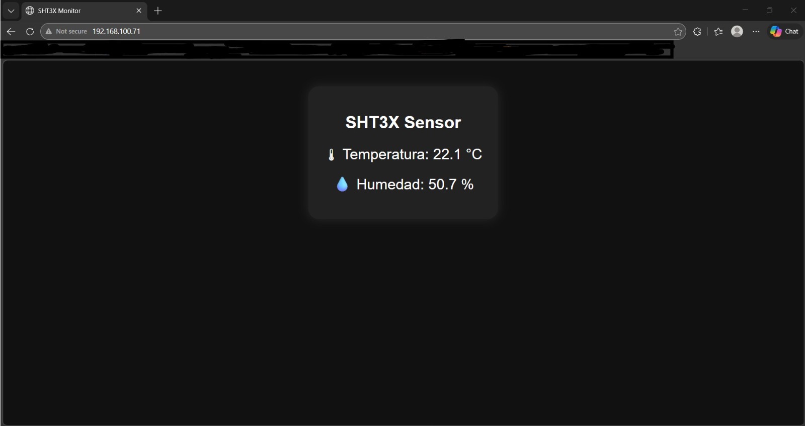
Moving from wires to invisible waves, I used the ESP32-C6's built-in Wi-Fi to create a local HTTP server on port 80. This allowed me to add my Smartphone and Laptop as new wireless nodes.
The ESP32 connects to my router and gets a local IP. I copied that IP into my browser. Using a C++ rawliteral string, I injected custom HTML and CSS directly from the microcontroller, including a <meta http-equiv="refresh" content="2"> tag so the client node auto-refreshes every 2 seconds to fetch live data!
WIRELESS ACCESS: Entering the local IP to load the live-refreshing Web Server.
SERVER INTERFACE
The HTML interface rendered directly from the ESP32 memory.
06. WIRELESS: ESP-NOW PROTOCOL
For my final project, I needed two completely separate PCBs to communicate across a soccer goal without running a fragile wire across the crossbar. Standard Wi-Fi is too slow and requires a router. My solution was ESP-NOW.
ESP-NOW is a connectionless communication protocol developed by Espressif that allows multiple ESP32 boards to talk to each other directly (Peer-to-Peer) with ultra-low latency.
THE MASTER / SLAVE TOPOLOGY
The Slave Board: Reads data from its local sensors. The moment an impact is detected, it packages the data into a C++ `struct` and fires it wirelessly into the air targeting the MAC address of the Master.
The Master Board: Constantly listens. When it receives the ESP-NOW payload from the Slave, it triggers a callback function to process the incoming data and update the OLED screen or Web UI.
ESP-NOW IN ACTION: Two custom ESP32-C6 boards communicating data wirelessly with zero latency.
07. THE CODE VAULT (DEEP DIVE EXPLANATION)
To ensure my work is fully replicable, here is a detailed breakdown of how the code operates for all tested protocols.
PART 1: THE ESP-NOW MASTER/SLAVE LOGIC
How to establish an ESP-NOW Connection:
Step 1: Get the MAC Address. Every ESP32 has a unique physical address (like `48:27:E2:XX:XX:XX`). The Slave board needs to know the Master's MAC address to know where to shoot the data.
Step 2: Initialize Protocol. We set the WiFi mode to WIFI_STA (Station mode) and call esp_now_init().
Step 3: Register Peer. Using the esp_now_peer_info_t structure, we tell the board about the existence of the other node and pair them on the same Wi-Fi channel.
Step 4: Callbacks. We create the OnDataSent function to verify if our message was delivered successfully, and the OnDataRecv function which automatically triggers the moment fresh data arrives.
#include <esp_now.h>
#include <WiFi.h>

// MAC Address of the Master Board (Receiver)
uint8_t masterAddress[] = {0x48, 0x27, 0xE2, 0x11, 0x22, 0x33};

// Structure to package the data
typedef struct struct_message {
  float impact_speed;
  int zone;
} struct_message;

struct_message myData;
esp_now_peer_info_t peerInfo;

// Callback: When data is sent
void OnDataSent(const uint8_t *mac_addr, esp_now_send_status_t status) {
  Serial.print("Last Packet Send Status: ");
  Serial.println(status == ESP_NOW_SEND_SUCCESS ? "Delivery Success" : "Delivery Fail");
}

// Callback: When data is received (On Master)
void OnDataRecv(const uint8_t * mac, const uint8_t *incomingData, int len) {
  memcpy(&myData, incomingData, sizeof(myData));
  Serial.print("Bytes received: ");
  Serial.println(len);
  Serial.print("Speed: "); Serial.println(myData.impact_speed);
}

void setup() {
  Serial.begin(115200);

  // Set ESP32 as a Wi-Fi Station
  WiFi.mode(WIFI_STA);

  // Initialize ESP-NOW
  if (esp_now_init() != ESP_OK) {
    Serial.println("Error initializing ESP-NOW");
    return;
  }

  // Register the peer
  memcpy(peerInfo.peer_addr, masterAddress, 6);
  peerInfo.channel = 0;
  peerInfo.encrypt = false;

  // Add peer
  if (esp_now_add_peer(&peerInfo) != ESP_OK){
    Serial.println("Failed to add peer");
    return;
  }
}

void loop() {
  // Send data from Slave to Master
  myData.impact_speed = 85.5;
  myData.zone = 2;

  esp_err_t result = esp_now_send(masterAddress, (uint8_t *) &myData, sizeof(myData));
  delay(2000);
}
PART 2: THE I2C MULTI-DEVICE LOGIC
How the I2C Code Works:
Line 7-10: Defines the I2C Addresses. 0x3C is standard for SH1106 displays. 0x44 is the factory address for the SHT31 sensor.
setup(): Calls Wire.begin() to initialize the hardware I2C pins. It then pings the OLED to verify it's connected.
Wire.beginTransmission(0x44): The ESP32 opens a connection to the sensor node.
Wire.write(0x24) & Wire.write(0x00): These are specific HEX commands from the SHT31 datasheet that tell the sensor to take a measurement.
Wire.requestFrom(0x44, 6): The ESP32 demands 6 bytes back (2 for Temp, 1 CRC, 2 for Hum, 1 CRC).
Bit Shifting:(data[0] << 8) | data[1] merges two 8-bit bytes into a single 16-bit integer so we can do the math to convert it to Celsius based on the datasheet's formula.