Week 10 Group Assignment - Output Devices
This week's group assignment is to measure the power consumption of an output device. We tested several types of output devices available in our lab:
- A DC motor
- A servo motor
- A stepper motor
- A passive buzzer
- A Neopixel ring
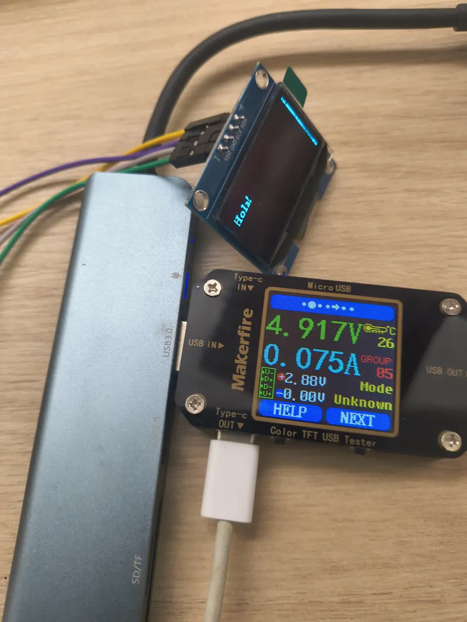
- An OLED display
For each device we measured the voltage and current to calculate power consumption. We tested some of the devices using a potentiometer, to see how power usage changes by adjusting parameters (such as motor speed or LED brightness). In here we documented the measured results from different instruments, set up diagrams showing how everything as connected, and the code used to control the devices for each test.
What are Output Devices?
An output device is a component that takes an electrical signal from the microcontroller and converts it into a physical effect. It can produce movement (motor), light (LED), sound (buzzer), or an image on a screen (display). They work along with input devices to create interactive systems: the microcontroller reads data from sensors (inputs), processes it and transform it into a effect in the real world (outputs).
Understanding how much power each device consumes is critical for designing safe circuits: it determines the power supply you need, it prevents system failures or safety hazards like overheating and it helps you optimize the components efficiency in our projects.
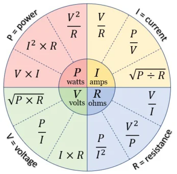
This image represents the Ohm's Law and Joule's Law Wheel. It shows the mathematical relationships between the four primary electrical quantities.
The Four Core Variables
The inner circle identifies the four variables and the units they are measured in:
- P (Power): Measured in Watts (W) This represents the rate at which electrical energy is consumed or produced meaning how fast electricity or work is done.
- I (Current): Measured in Amps (A). The flow of electric charge through a conductor.
- V (Voltage): Measured in Volts (V). Known as electrical potential difference, it represents the electrical pressure that pushes the current.
- R (Resistance): Measured in Ohms (Ω). This is the opposition to the flow of current.
Why use this formula? Voltage and current are the easiest electrical quantities to measure directly with common instruments like multimeters and USB testers. Rather than trying to measure power or resistance directly, we simply measure volts and amps, then multiply them together to get power instantly.
Example
A servo motor running at 6 V draws 0.3 A while moving. Meaning it consumes 1.8 W
P = 6 V × 0.3 A = 1.8 W
Power Consumption Tests
What is a DC Motor?
A DC (Direct Current) motor converts electrical energy into rotational mechanical energy. When a DC voltage is applied across its terminals, the motor shaft spins. The direction of rotation depends on the polarity, and the speed depends on the voltage level. To control a DC motor with a microcontroller, an H-bridge driver IC is needed: it allows the microcontroller's low-current signals to safely switch the higher motor current, and also enables forward/reverse direction control.
Motor used: MOT-050 rated at 6V, controlled via L298N H-bridge with a potentiometer for speed control. It is powered through a 9V battery connected to a breadboard power supply module that converts it to 5V.
What is a Neopixel Ring?
A Neopixel ring is a circular, rigid printed circuit board (PCB) featuring a chain of individually addressable, super-bright RGB or RGBW LEDs. They utilize WS2812B or similar driver chips integrated directly into the LEDs, allowing all pixels to be controlled via a single digital input pin.
LED ring used: WS2812B NeoPixel ring, connected to the custom PCB via 5 V, GND and Data (GPIO).
Summary
The table below compares the power consumption of all devices tested. This is useful to understand which devices are power-hungry and which can be safely powered directly from a USB source or a microcontroller pin.
Power Consumption Comparison
| Device | Voltage (V) | Current (A) | Power (W) | Notes |
|---|---|---|---|---|
| DC Motor | 5.0 | 0.065 – 0.399 | 0.33 – 2.00 W | Low to full speed, no load |
| Servo Motor | 5.0 | 0.350 | 1.75 W | Average while sweeping |
| Stepper Motor (slow) | 12.0 | 0.550 | 6.60 W | More current at low speed (back-EMF) |
| Stepper Motor (fast) | 12.0 | 0.250 | 3.00 W | Less current at high speed |
| Passive Buzzer | 4.995 | 0.026 | 0.130 W | Average while playing tone |
| Neopixel Ring (max) | 4.937 | 0.247 | 1.219 W | All LEDs full white brightness |
| Neopixel Ring (avg color) | 4.950 | 0.270 | 1.300 W | Average across all color tests |
| OLED Display (text) | 4.920 | 0.075 | 0.369 W | Includes PCB system overhead |
Conclusions
Measuring power consumption directly gave us a much more concrete understanding of what each device actually demands from a circuit. Some key takeaways:
- Motors require external power: All three motor types drew significantly more current than a microcontroller GPIO pin can supply. Always use a driver IC and an external power supply for motors.
- Stepper motors draw current even at rest: Unlike DC or servo motors that idle at very low current, a stepper motor in holding mode continuously energizes its coils, which causes heating and wastes power. Consider disabling the driver when holding is not required.
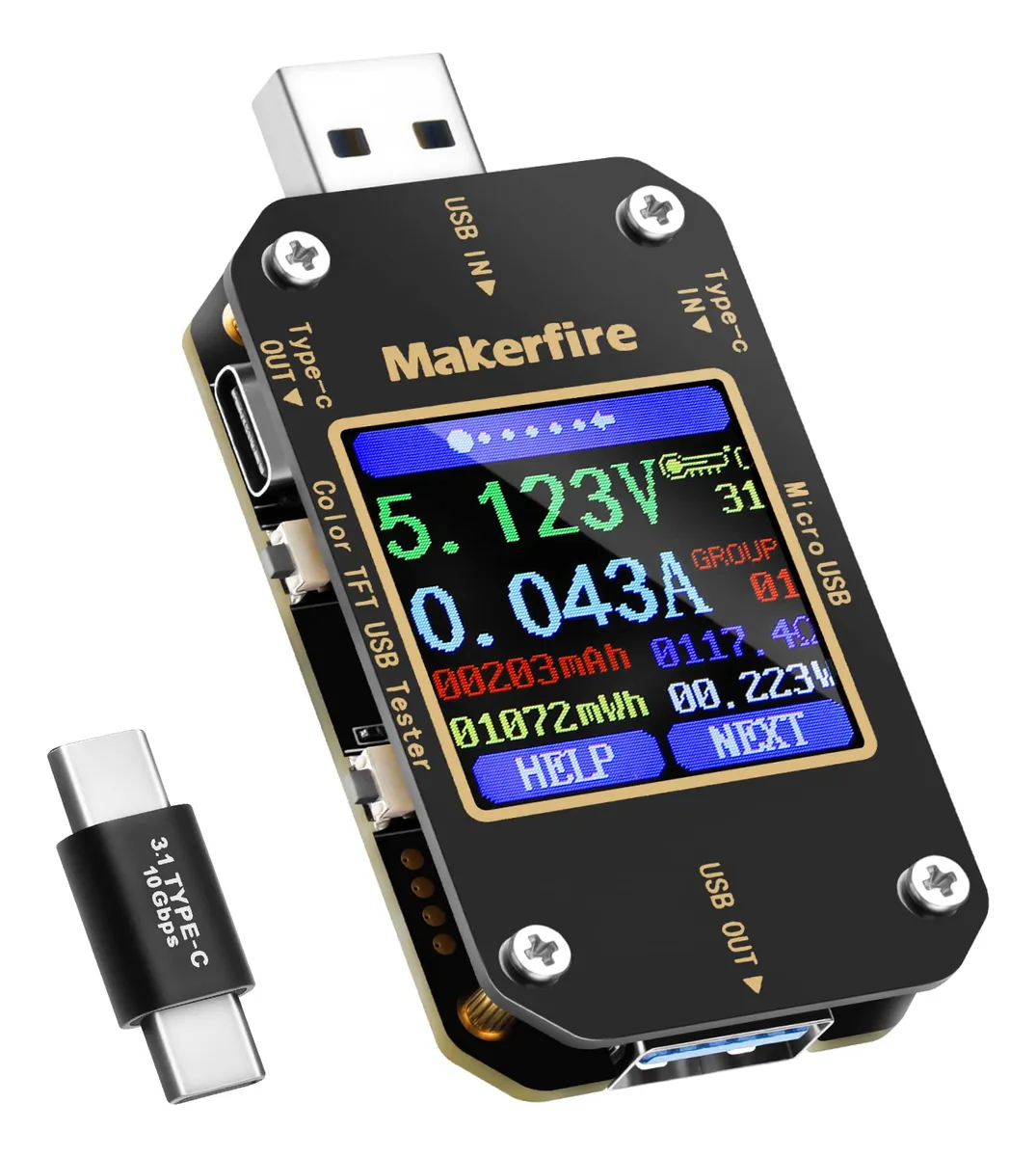
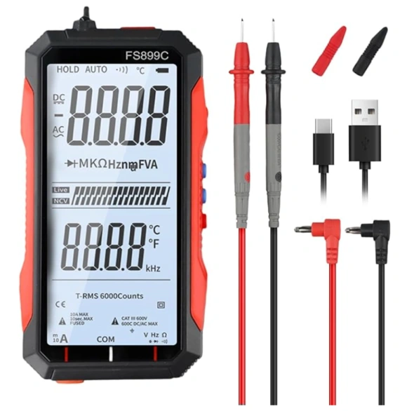
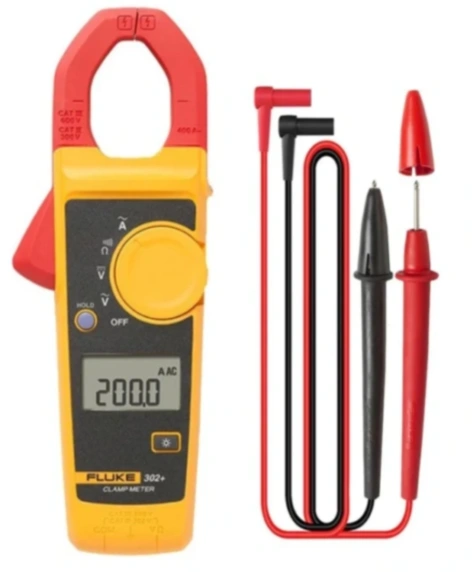
- The USB tester is ideal for 5 V devices: Its in-line convenience makes it perfect for quick tests on USB-powered boards. The multimeter in series is better for non-USB circuits, and the clamp meter is best reserved for high-current or AC applications.