At Fab Lab Puebla, our in-house PCB production workflow is supported by two specialized machines: the Roland MonoFab SRM-20, a high-precision compact milling machine, and the xTool F1 Ultra, a dual-source fiber and diode laser system. We utilize these tools to characterize and compare mechanical milling versus laser ablation, allowing us to establish the specific design rules and tolerances required for reliable circuit fabrication.
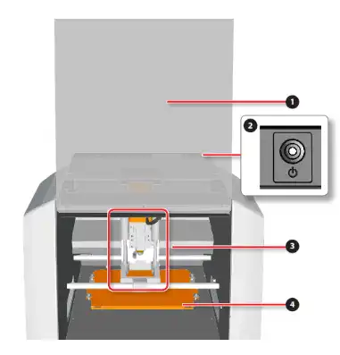
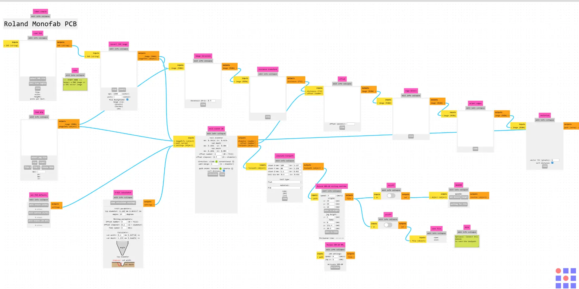
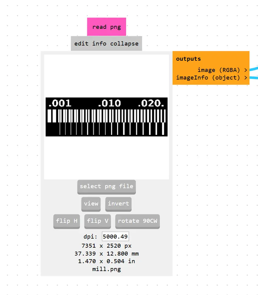
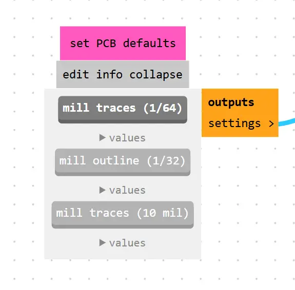
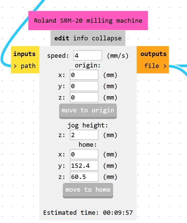
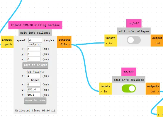
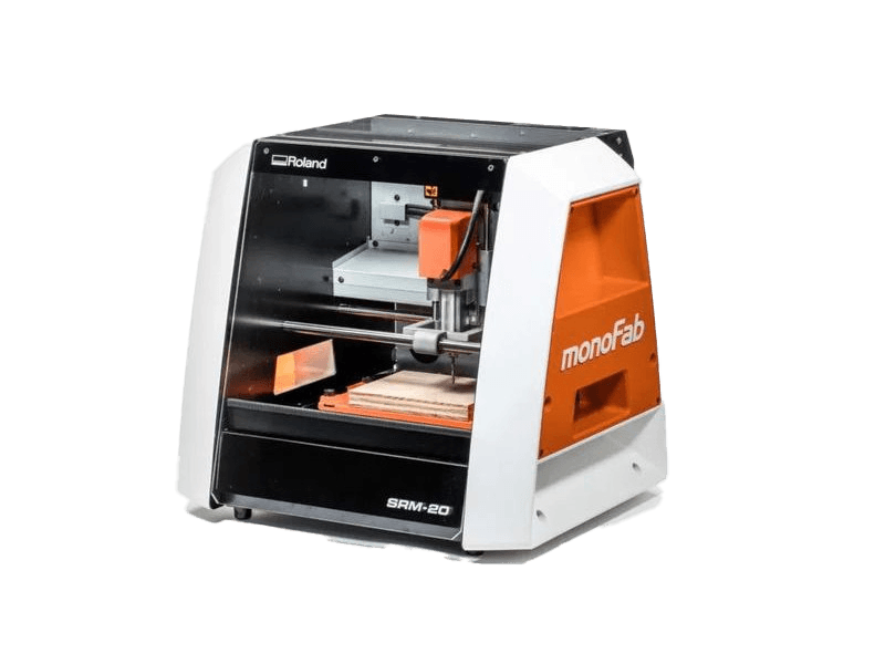
The Roland SRM-20 is a compact CNC desktop milling machine used for prototyping, PCB milling, and small mechanical parts. It removes material using rotating cutting tools.
| Material | Description | Common Uses |
|---|---|---|
| Modeling Wax | Soft machinable wax | Jewelry molds, casting models |
| Chemical Wood | Dense resin-based board | Functional prototypes |
| Acrylic (PMMA) | Transparent thermoplastic | Enclosures, panels |
| PCB copper boards | Copper-clad laminates | Electronic circuit boards |
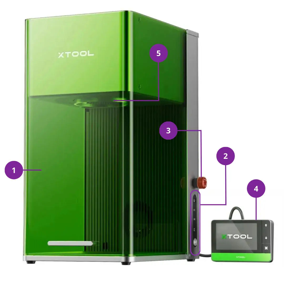
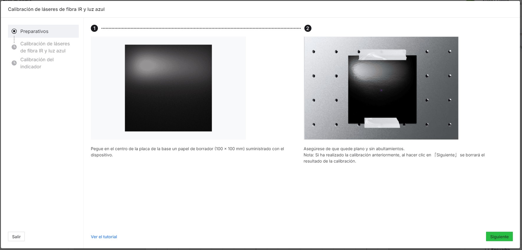
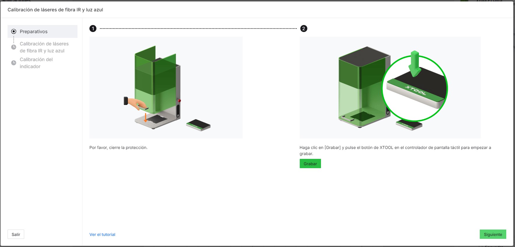
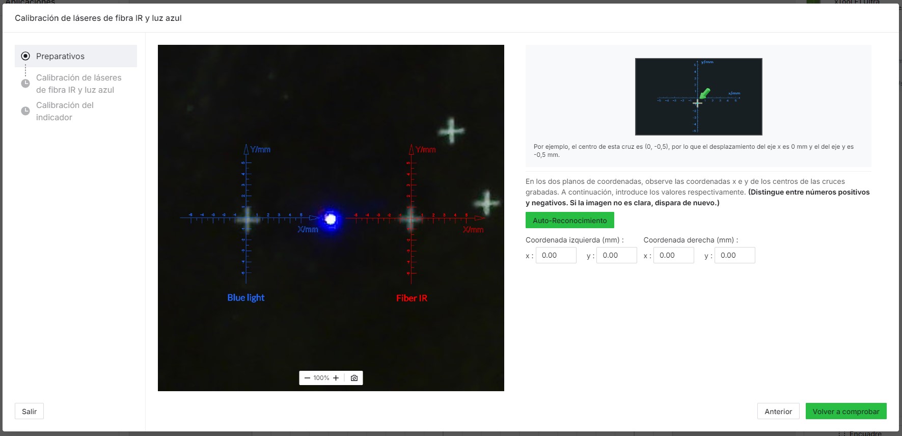
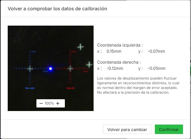
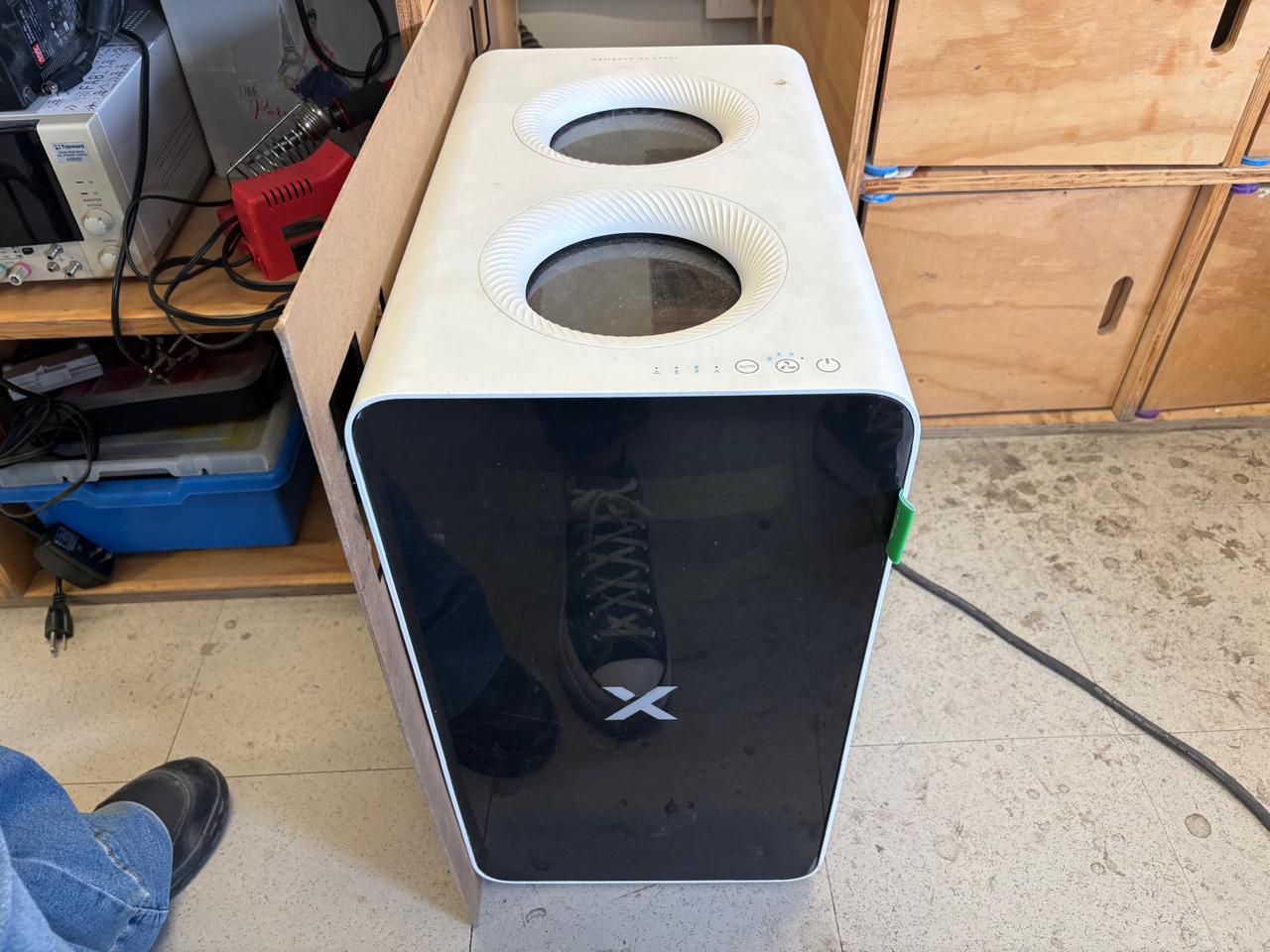
The xTool F1 Ultra is a dual-laser engraving and cutting system combining a 20 W fiber laser and a 20 W diode laser for processing both metals and non-metals.
| Material | Description | Common Uses |
|---|---|---|
| Stainless Steel | Corrosion-resistant metal | Tags, industrial marking |
| Aluminum | Lightweight metal | Electronics housings |
| Wood / Leather | Organic / Natural material | Crafts, accessories |
| Ceramics / Stone | Hard brittle material | Decorative engraving |
Both machines incorporate specific safety systems to protect the operator from mechanical and radiation hazards.
| Roland SRM-20 (Mechanical Safety) | xTool F1 Ultra (Laser Safety) |
|---|---|
|
|
Standard settings for common operations on both machines:
| Machine | Parameter | Typical Value/Range |
|---|---|---|
| Roland SRM-20 (PCB Milling) |
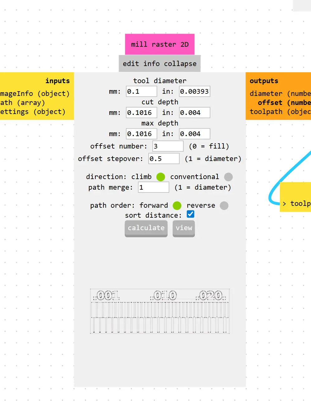
Tool diameter | 0.1 – 0.4 mm |
| Feed rate | 100 – 250 mm/min | |
| Cut depth | 0.05 – 0.15 mm | |
| xTool F1 Ultra (Laser Engraving) |
Laser power | 10 – 100% |
| Engraving speed | 100 – 10,000 mm/s | |
| Passes | 1 – 10 (material dependent) |
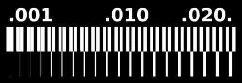
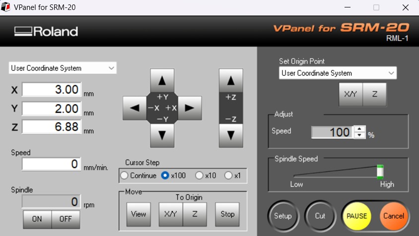
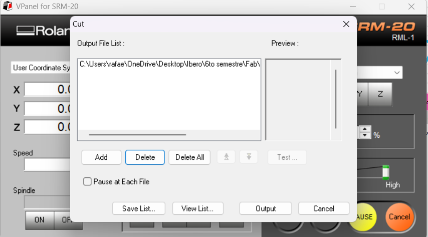
After running the clearance and width test files, these are the results obtained on the SRM-20. This test is crucial to determine the machine's resolution and the limits of the tool being used.
Applied Parameters:
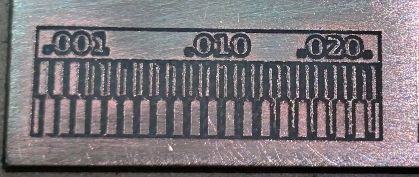 Fig 1. Minimum Clearance and Width - Results
Here is the result for the Engrave Test.
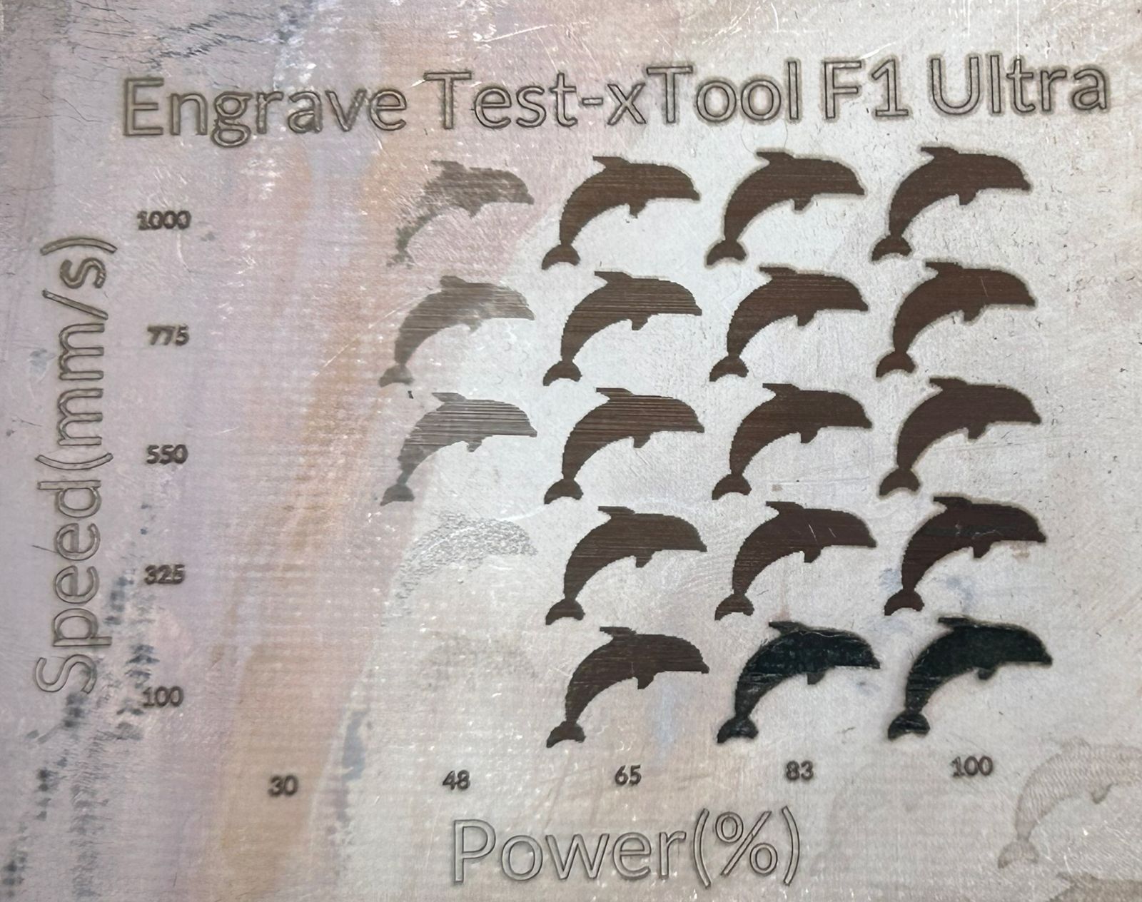 Fig 2. Engrave Test
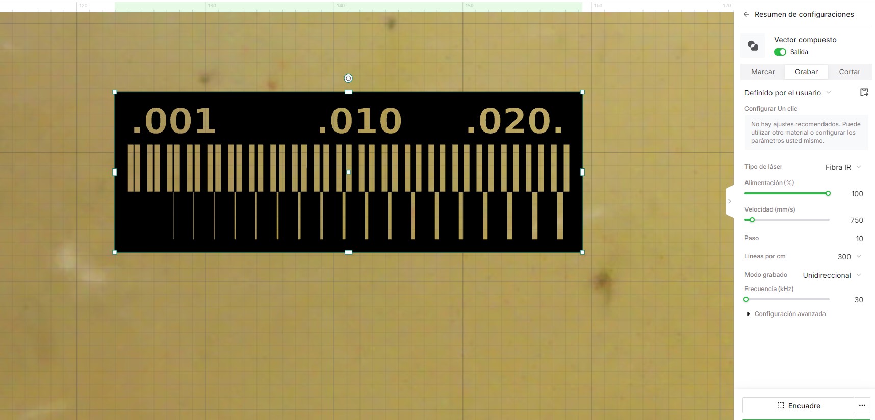
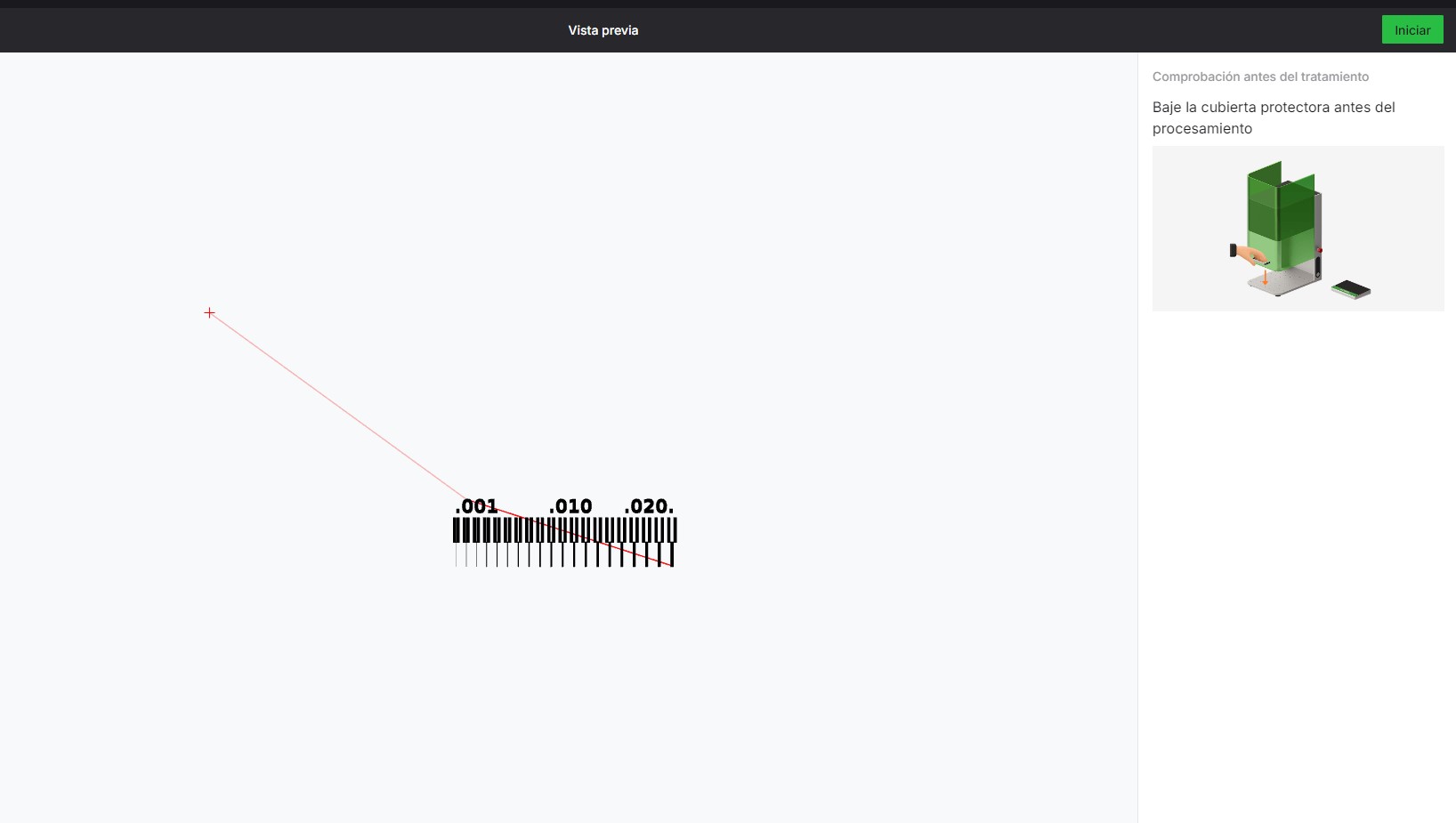
After running the clearance and width test files, these are the results obtained on the XTool.
Applied Parameters:
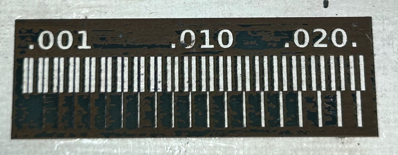 Fig 3. Minimum Clearance and Width - Results
| Feature | Roland SRM-20 | xTool F1 Ultra |
|---|---|---|
| Fabrication method | CNC milling | Laser engraving/cutting |
| PCB capability | Yes (PCB milling) | Not ideal for PCB milling |
| Metal processing | Not supported | Yes |
| Waste produced | Chips and dust | Smoke and fumes |
| Typical use | PCB prototyping, small parts | Engraving, marking, laser cutting |
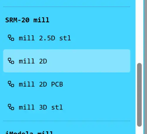
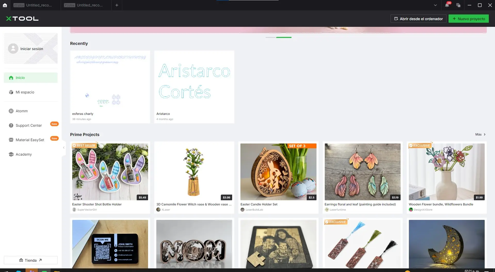
One assignment this week is to upload a PCB design to a board house, for which we use JLCPCB. For this step, remember that you must have a ZIP folder ready containing the Gerber files from your board design.
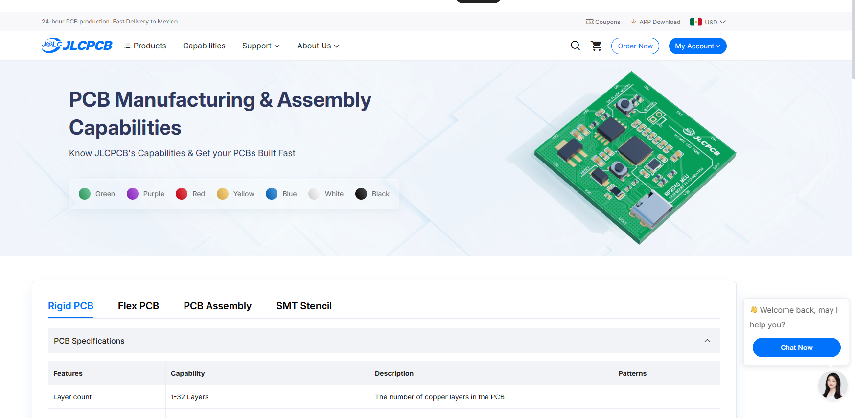
Select Order Now, and the menu will appear where you can upload your folder.
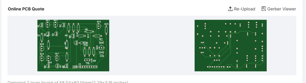
After you have uploaded your folder, you will see a preview of your board so you can confirm that everything is correct. It is important that the folder includes all the layers you want to appear on the PCB.
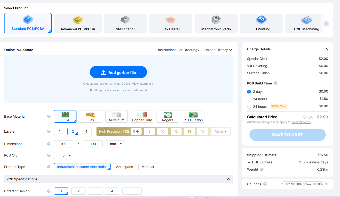
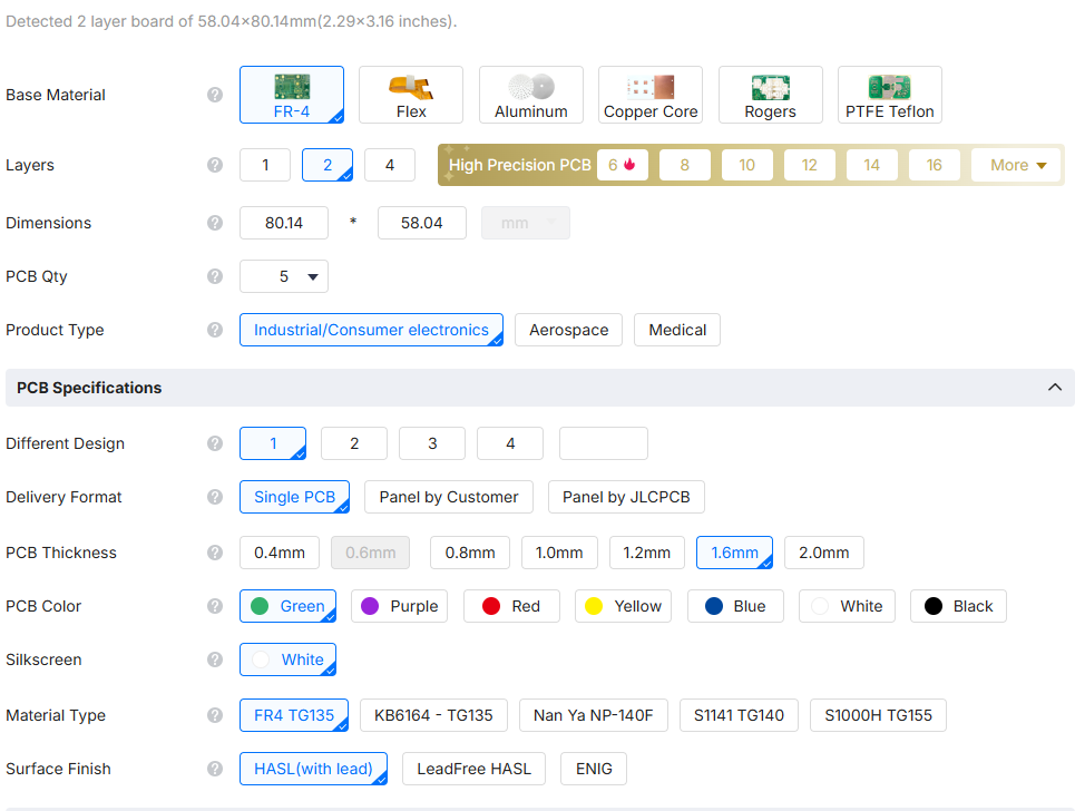
In this menu, we can customize our PCB by changing the base material, the thickness, the color, and many other parameters. We can also select the quantity of PCBs we want, with a minimum order of 5. For this project, I left the default parameters as they were appropriate for the design.
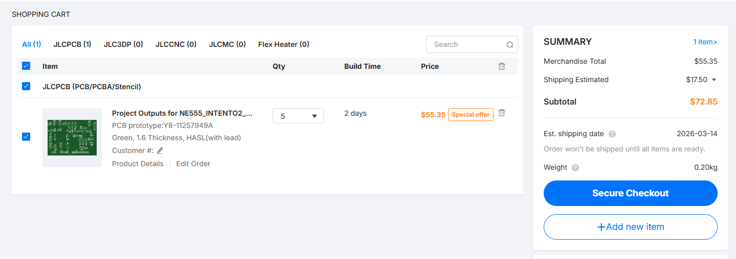
We add our order to the cart. Here, we can see the estimated cost and also modify the lead time, depending on whether we have minimum or maximum urgency for the boards to be ready.
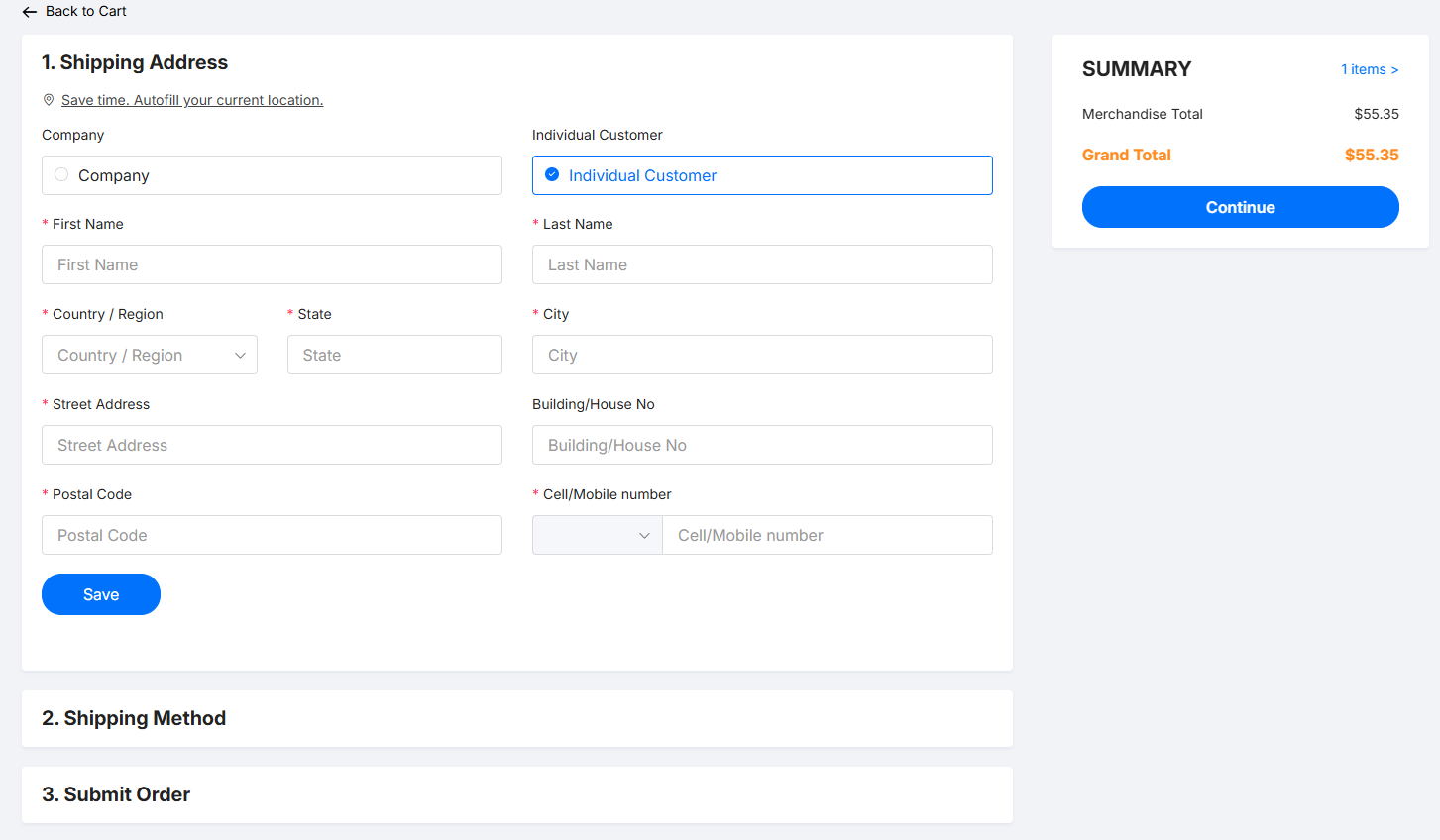
Here you can select the shipping address, the shipping method, and finally submit the order.
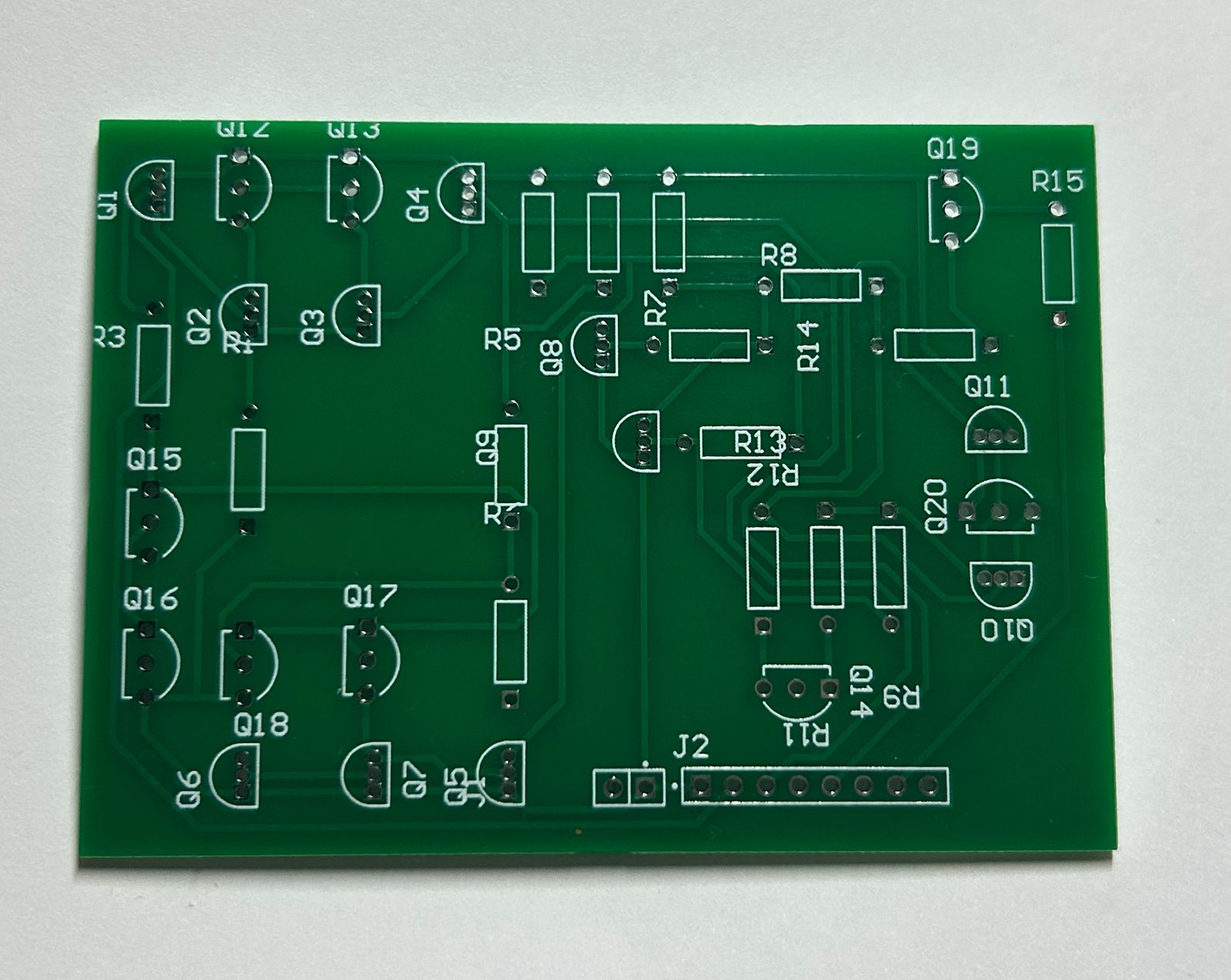
After you have placed your order, you can log in to the website to track the manufacturing progress of your board. Once the PCB is finished, delivery typically takes between 5 to 7 business days, depending on the shipping company you chose and your delivery address. Finally, here is the result of the manufactured board.