The inspiration for this project comes from my personal experience. I was diagnosed with hearing loss at the age of seven, and since then, one of my biggest challenges has been identifying the source of sounds—especially while walking or moving around. Often, I found it so difficult to determine when someone is speaking to me and from which direction.
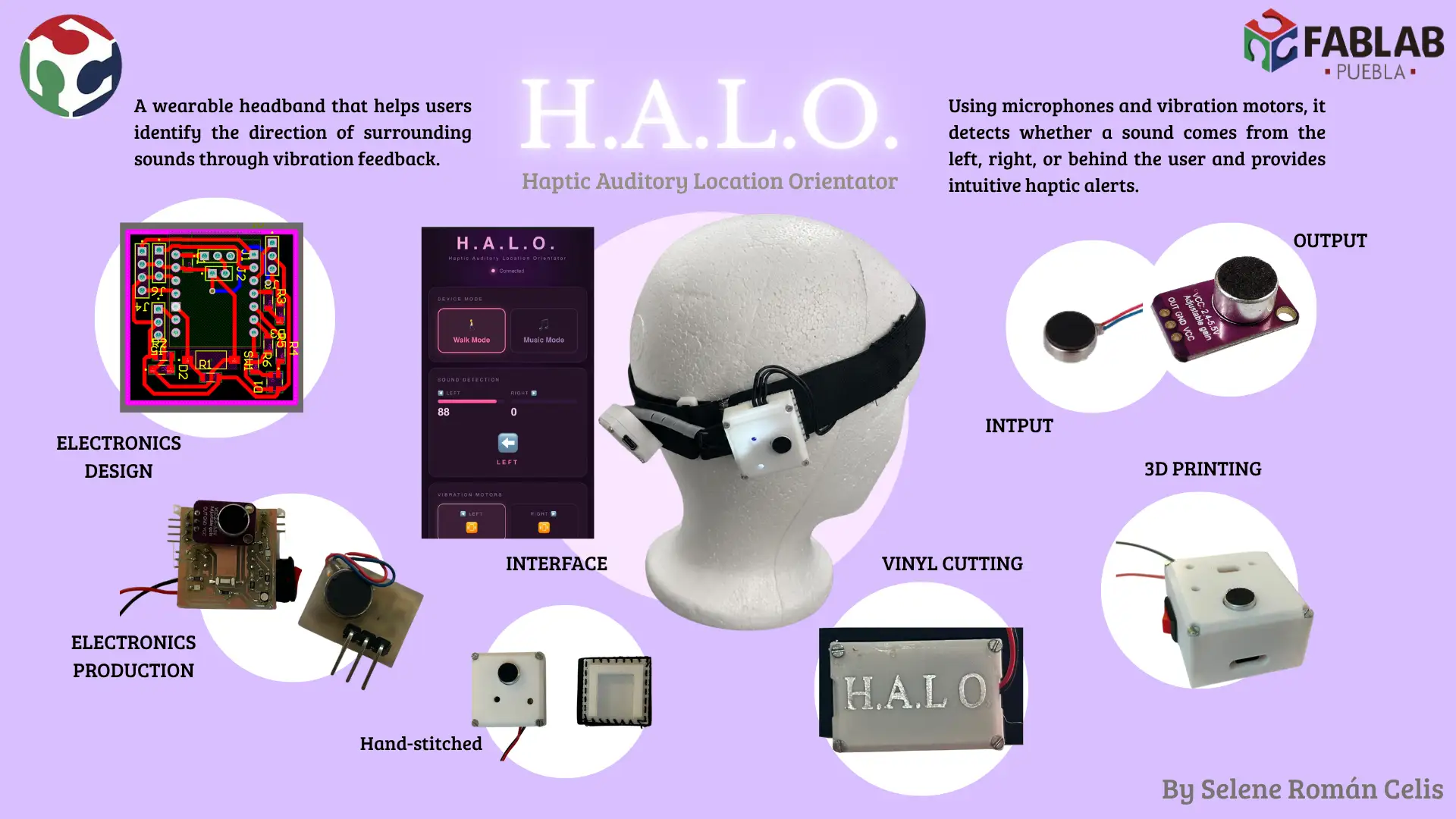
Driven by this need, I am developing a wearable device designed to restore the user's sense of auditory orientation. The system detects the source of loud sounds and uses strategic haptic feedback (vibration patterns) to indicate exactly where they are coming from.
Furthermore, this project aims to go beyond safety and assistance; it integrates a feature that transforms music into vibrations. This enriches the sensory experience, allowing people with profound hearing loss or deafness to 'feel' the music and reconnect with their environment in a new way.
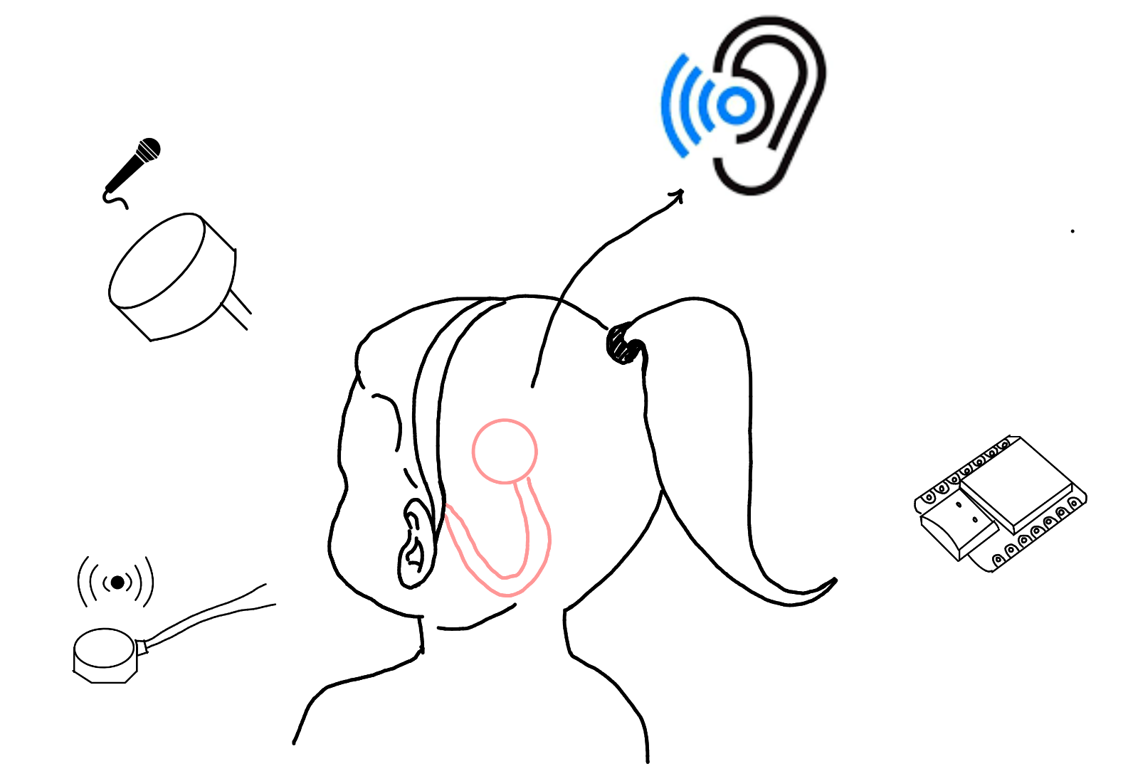 Fig 1. Project sketch
The project will use basic microphones placed on different sides of the wearable to detect surrounding sounds. By comparing the signals, the system will estimate from which side the sound is coming.
A small microcontroller, such as a XIAO series board, will be used to read the microphone data and make simple decisions based on sound intensity and direction.
Small vibration motors will provide feedback to the user. Each vibration pattern will represent a direction, helping the user understand where the sound is coming from through touch.
The device will be powered by a compact battery, allowing it to be wearable and portable. Basic voltage regulation will be included to safely power the electronics.
The structure will be designed as a wearable object (like a clip or band) and fabricated using 3D printing or flexible materials to comfortably hold the electronic components.
To achieve the final result, I have mapped the development of the device to the weekly assignments:
| Product | Quantity | Price (USD) | Source |
|---|---|---|---|
| Male Pin | 28 | 6 | Mercado Libre |
| 10k Resistor | 1 | - | - |
| 303 Resistor | 7 | - | - |
| 10uF Capacitor | 1 | - | - |
| XIAO ESP32-C6 | 1 | 7 | Unit Electronics |
| LED | 4 | - | - |
| Push Button | 1 | - | - |
| Switch | 1 | - | - |
| RGB LED | 1 | - | - |
| MAX4466 Microphone Module | 2 | 4 | Mercado Libre |
| Battery LiPo 3.7V | 1 | 2 | Steren |
| Vibration Motor | 2 | 1 | AliExpress |
| Elastic Band | 1 m | 1 | Parisina |
| PLA Filament | - | 20 | Inova Market |
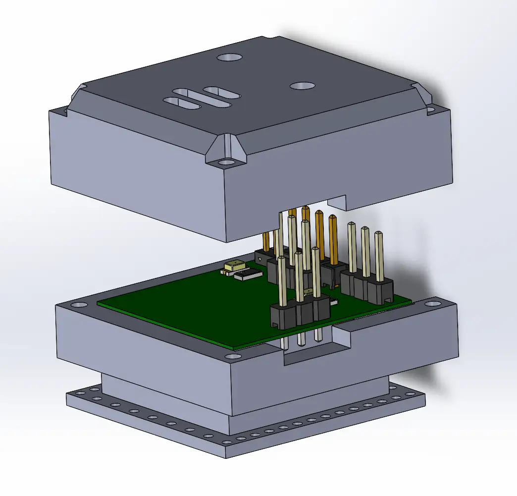
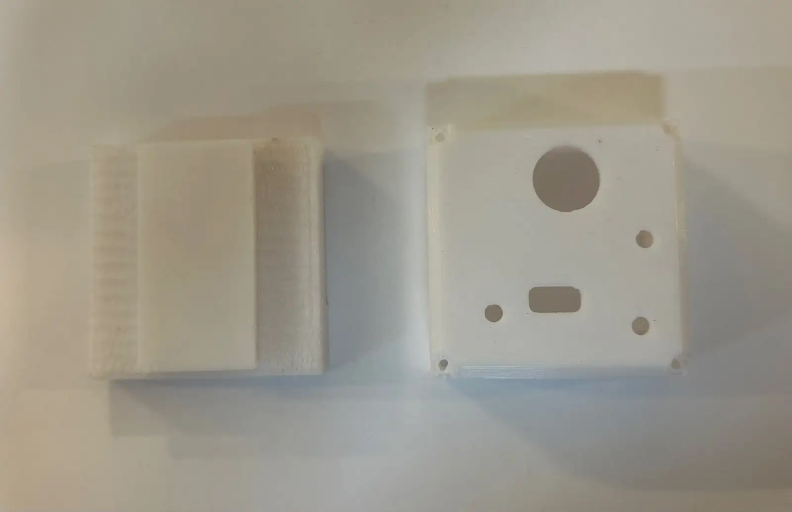
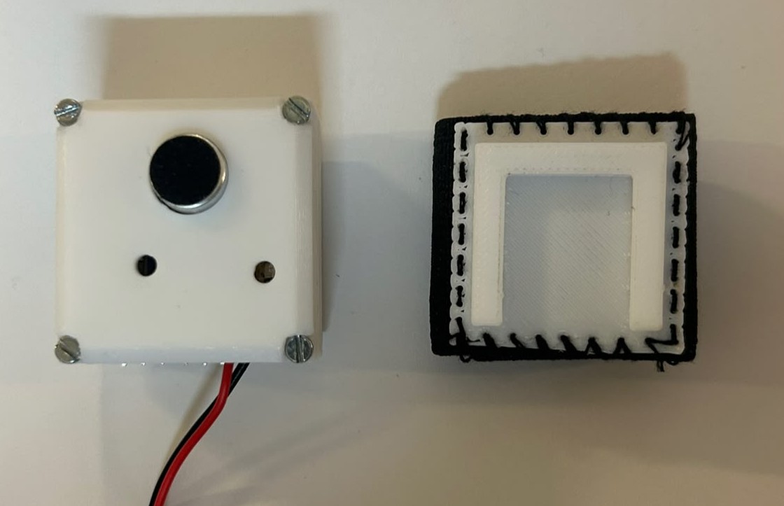
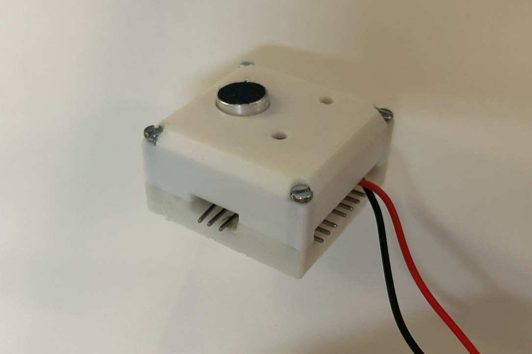
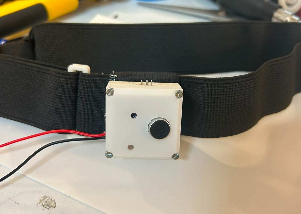
For the mechanical design, I created two custom enclosures, one for each side of the headband. Each enclosure consists of two pieces that protect the electronics while providing a cleaner and more finished appearance.
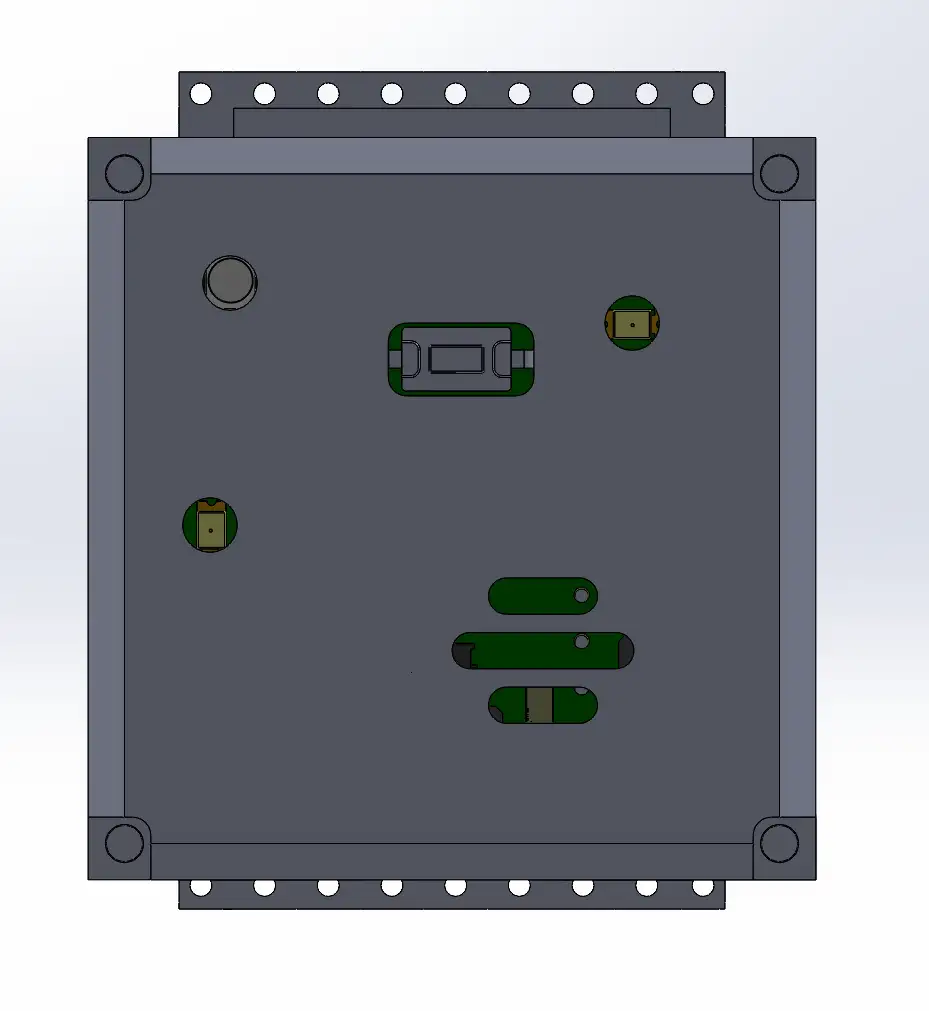
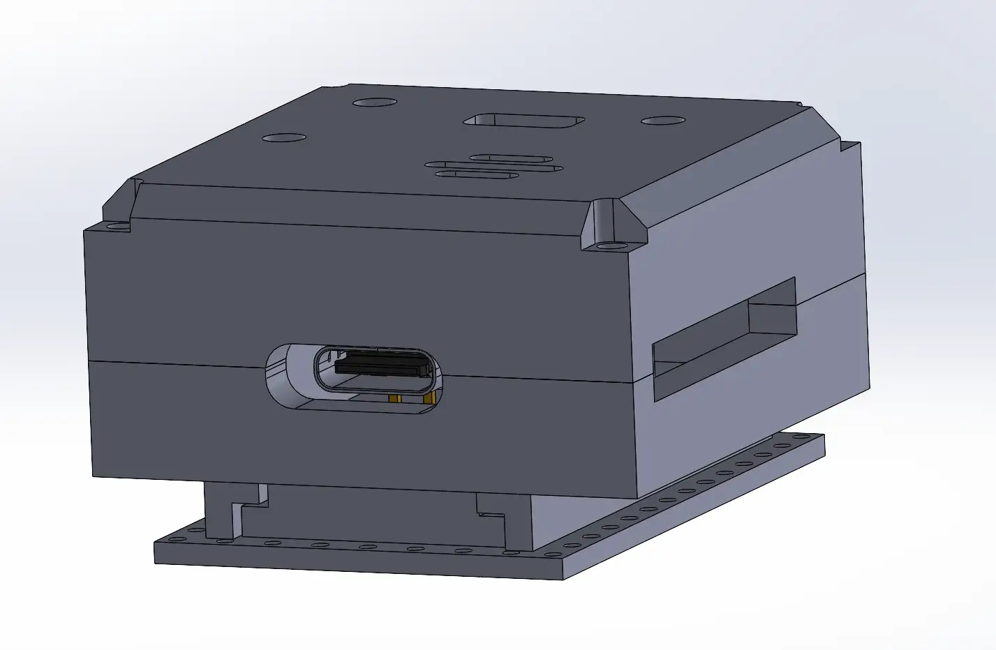
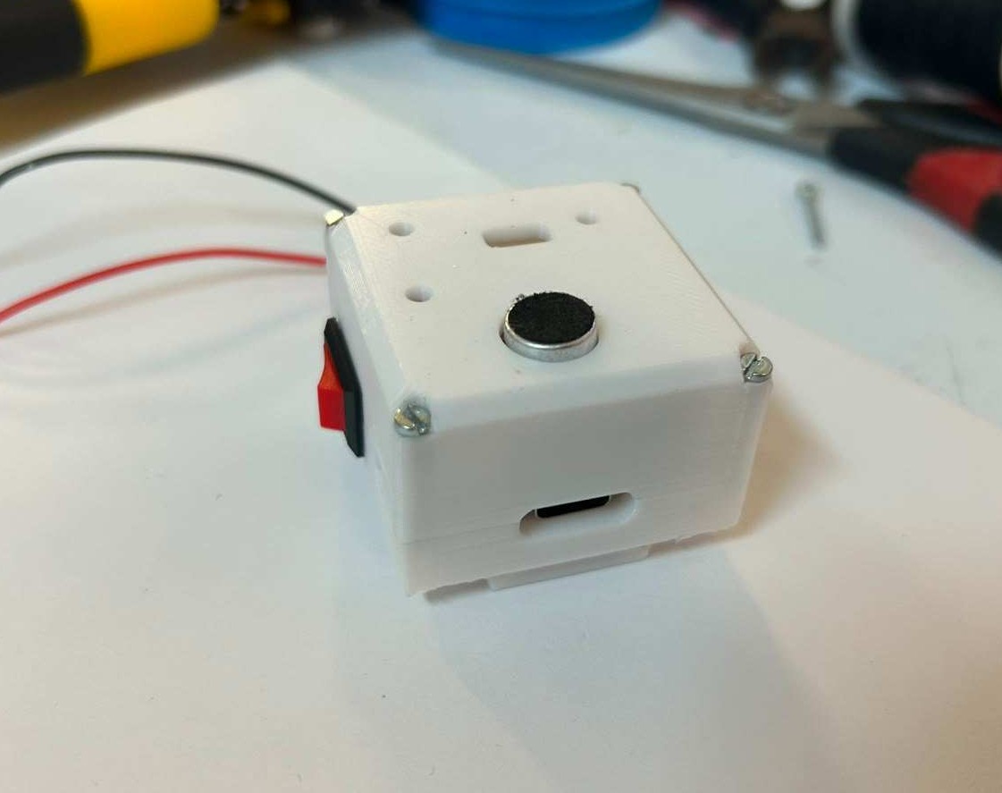
This is the enclosure for the main PCB. It includes an opening for the USB-C port so the XIAO ESP32-C6 can be programmed, as well as an opening for the power switch used to turn the entire system on and off.
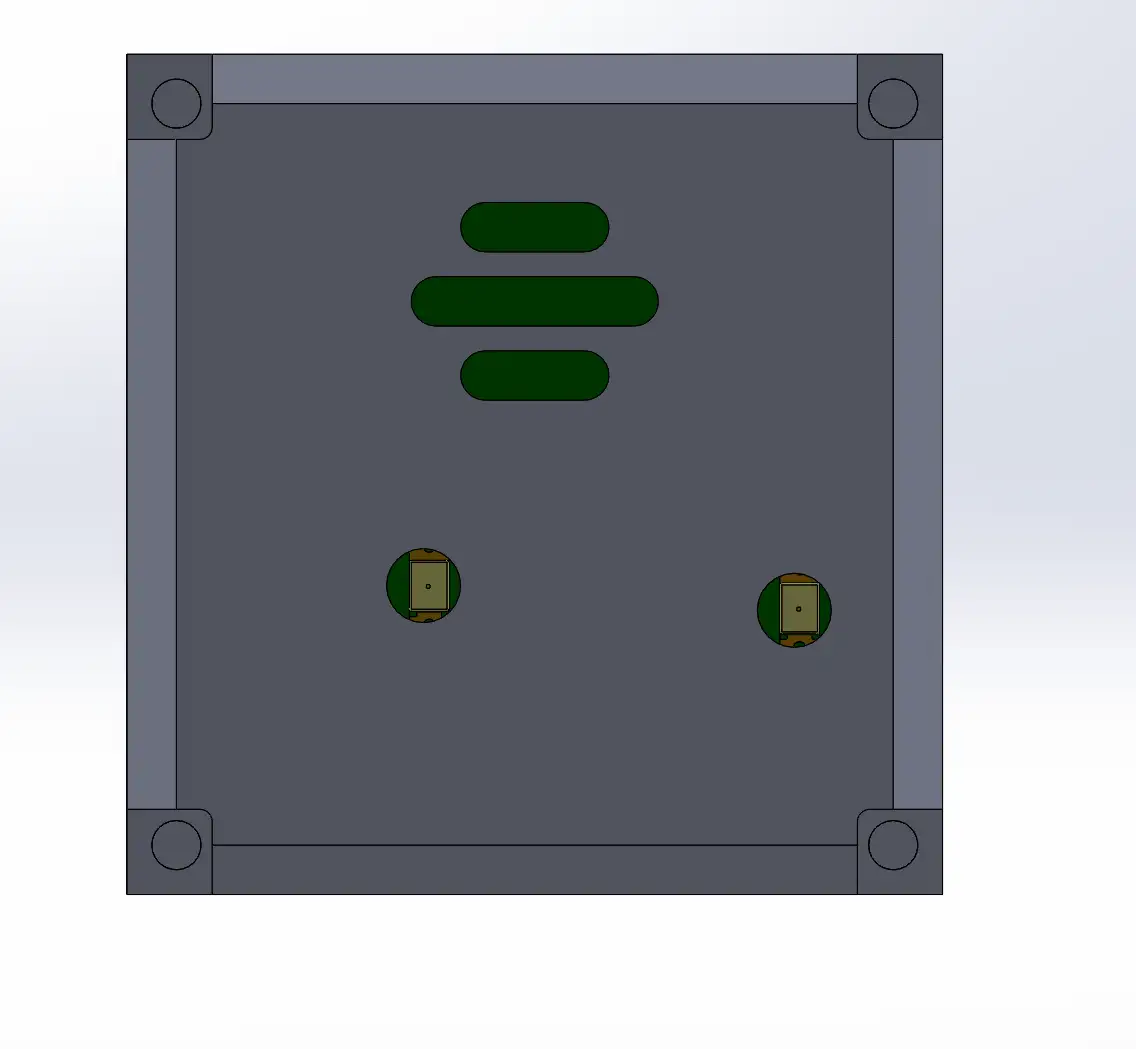
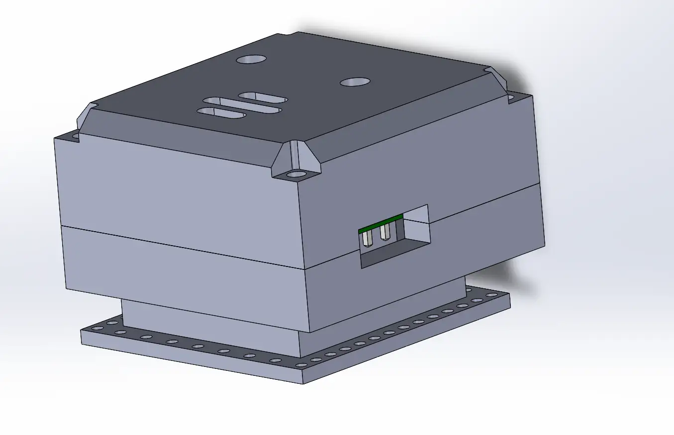
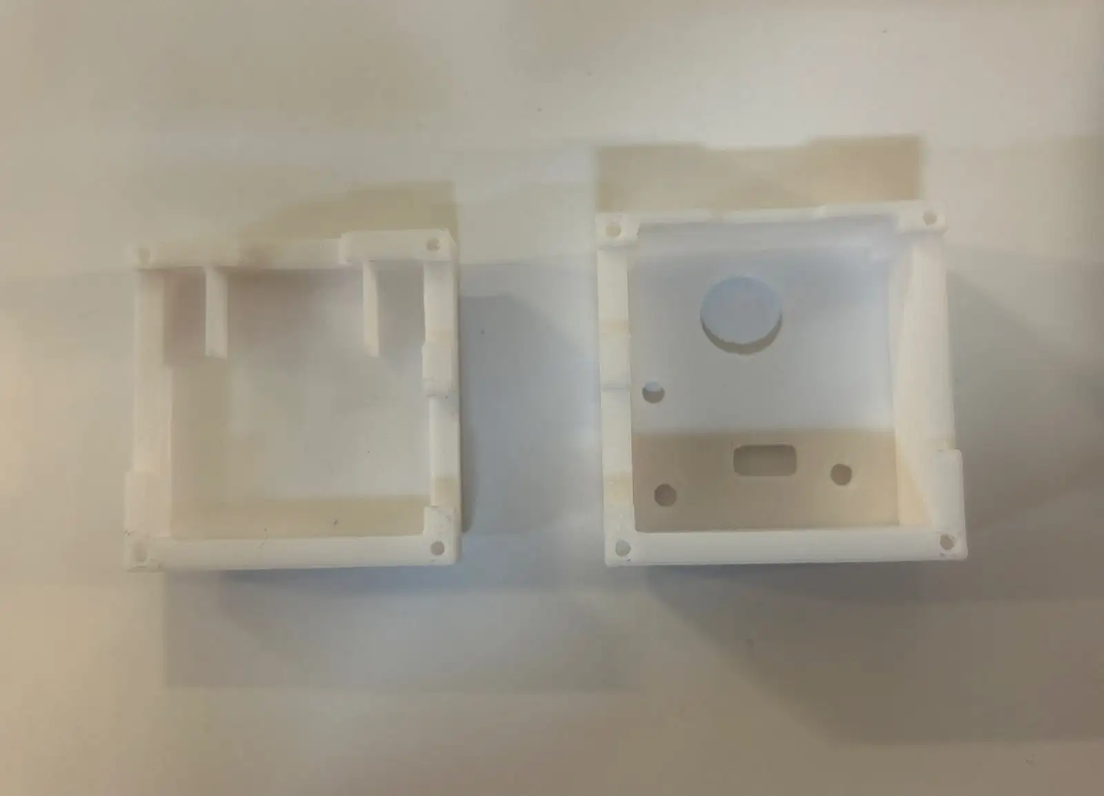
This is the enclosure for the secondary PCB. To better verify that the enclosure dimensions were correct, I exported the PCB designed in Altium into SolidWorks and added it to an assembly.
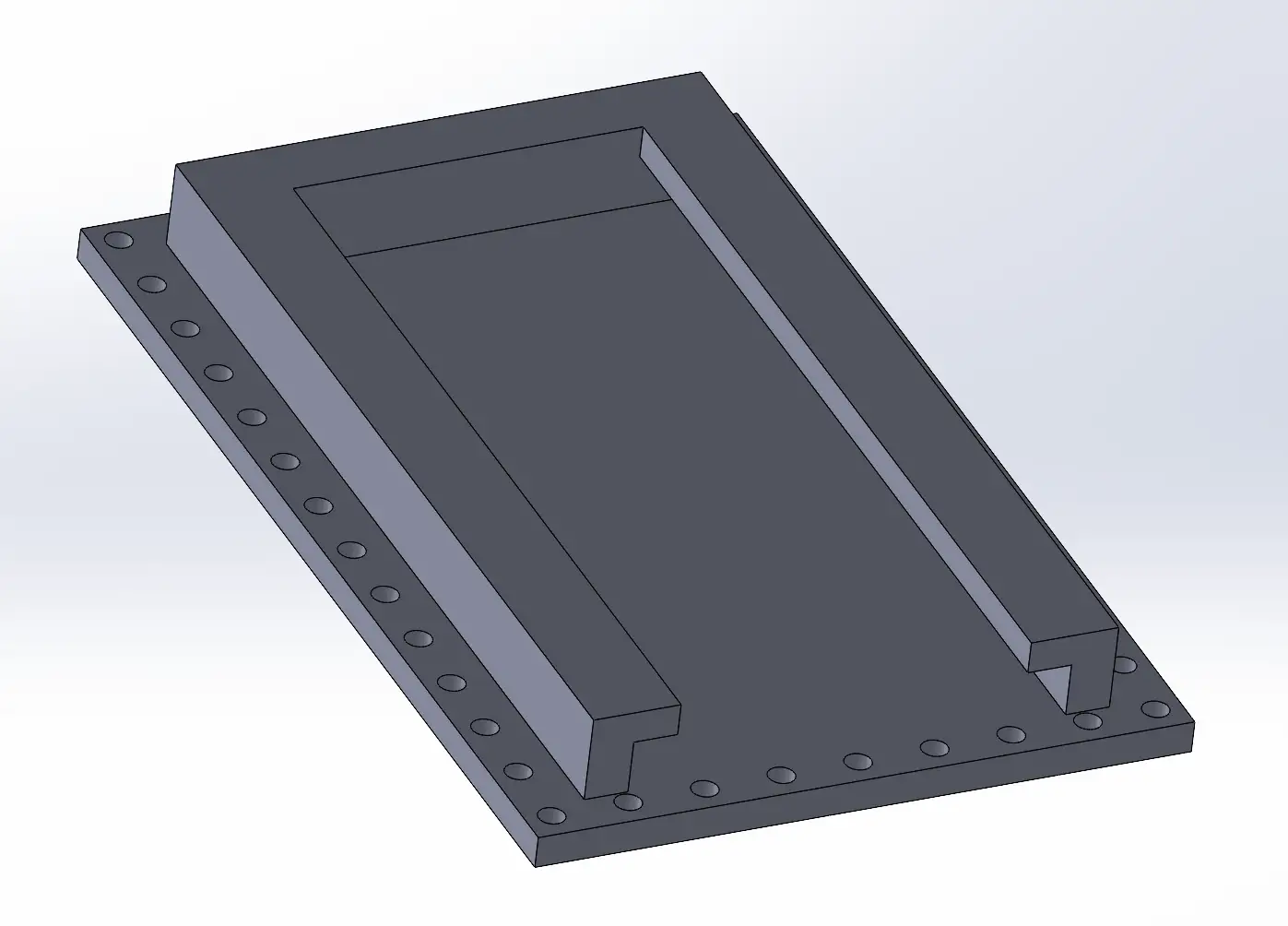
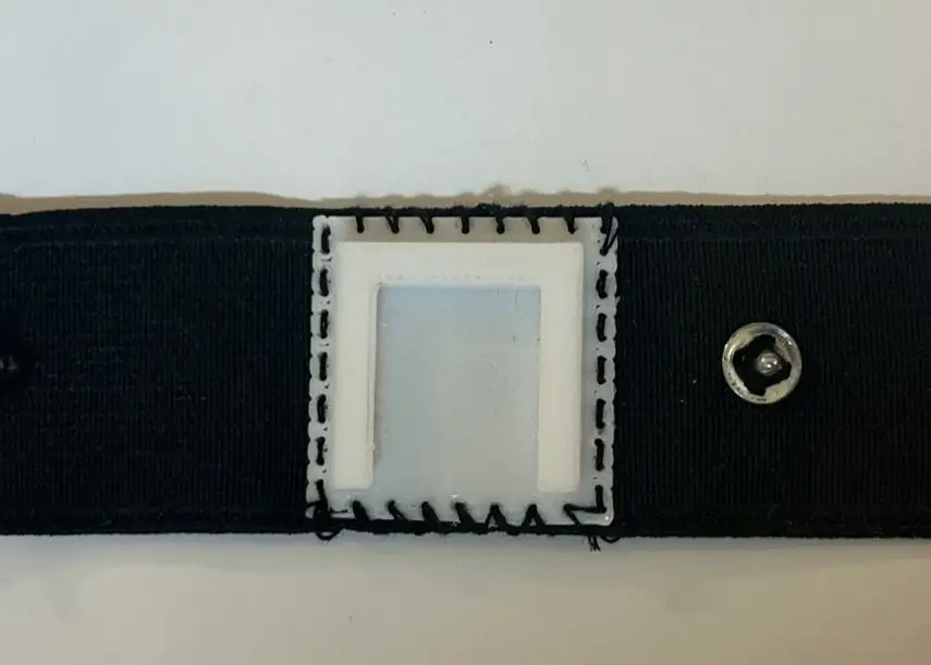
I also designed a bottom mounting piece that allows the enclosure to be attached to the fabric headband. This piece will be sewn directly onto the fabric using a needle and thread.
I saved all the designed parts as STL files and opened them in PrusaSlicer. To generate the files required for 3D printing on this machine, I followed the same process described in Week 5, where the slicing workflow and printer setup are explained in detail.
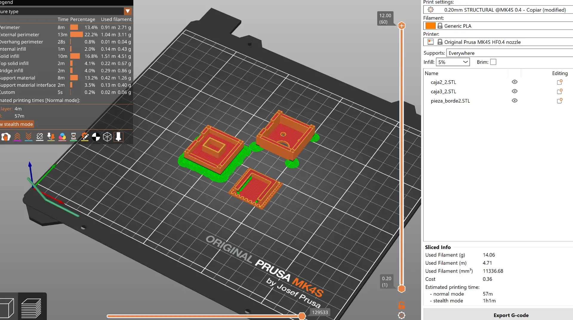
These are the final 3D printing results of the designed enclosures.
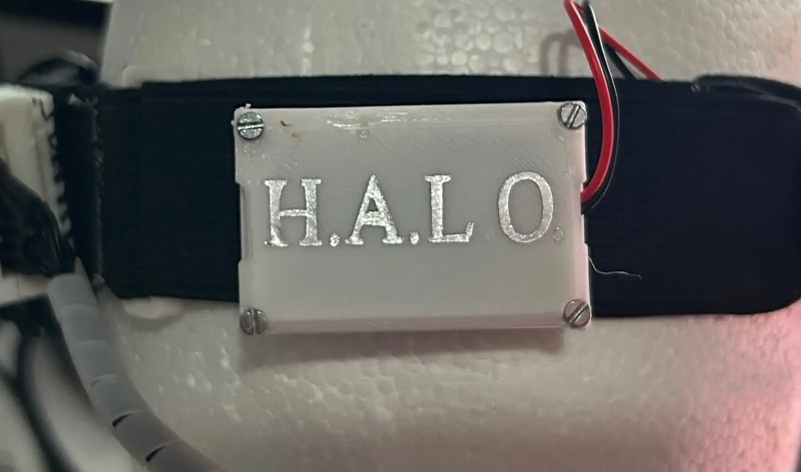
For the Subtractive Fabrication Processes assignment, I created a vinyl cut of my project's name to place on the 3D-printed part attached to the headband. For more information about the vinyl cutter and the cutting process, refer to the documentation from Week 3.
After the testing performed during the Week 10 assignment, I designed and fabricated the final PCBs for my project.
The system consists of three different boards:
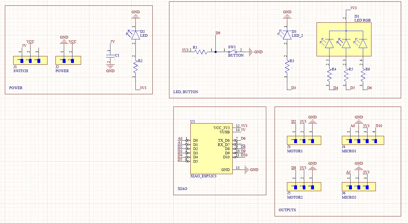
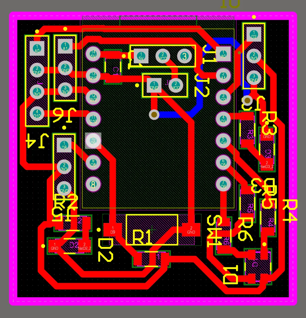
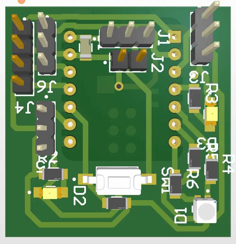
The main PCB contains the XIAO ESP32-C6, the microphone and vibration motor connections for the left side of the headband, and an RGB LED used to indicate the different operating modes. This board also includes the connections that link it to the secondary PCB.
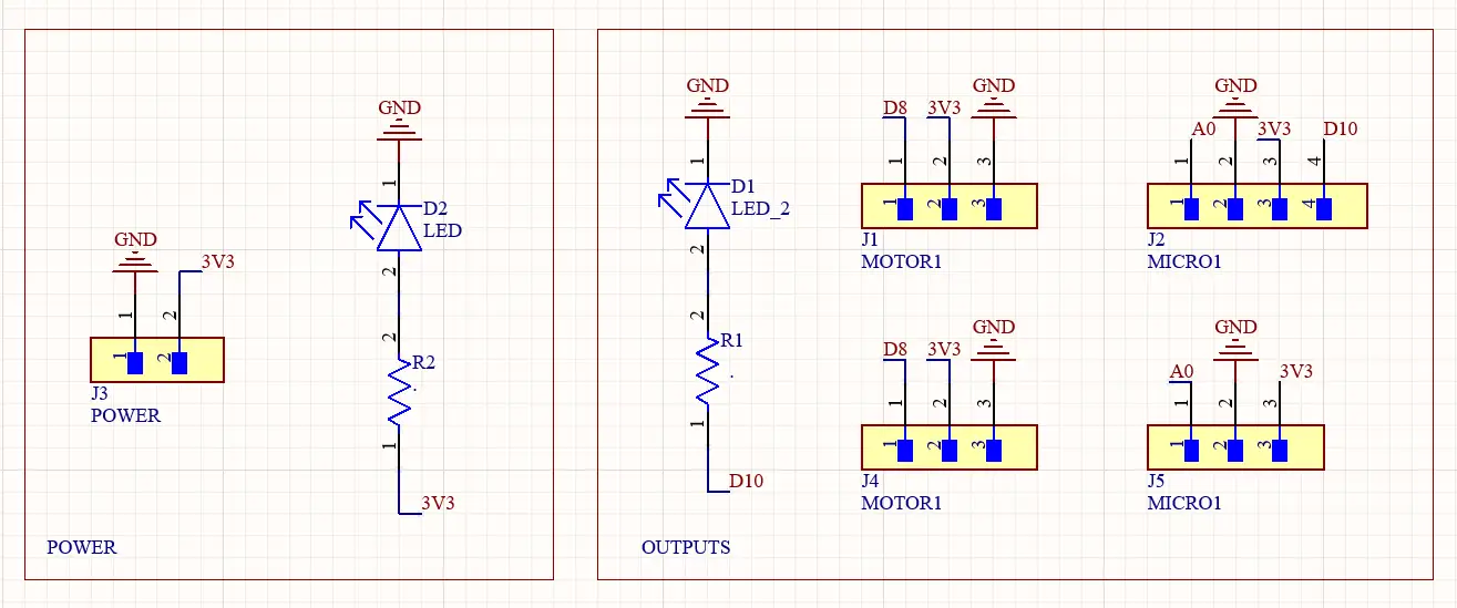
The secondary PCB receives power and signals from the main board and provides the connections for the microphone and vibration motor located on the right side of the headband.
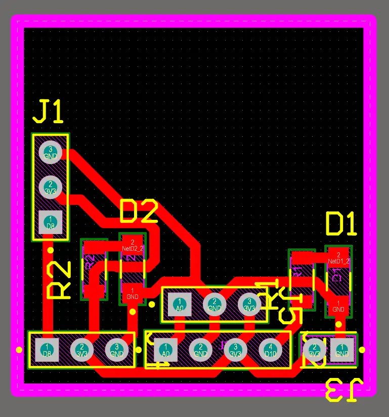
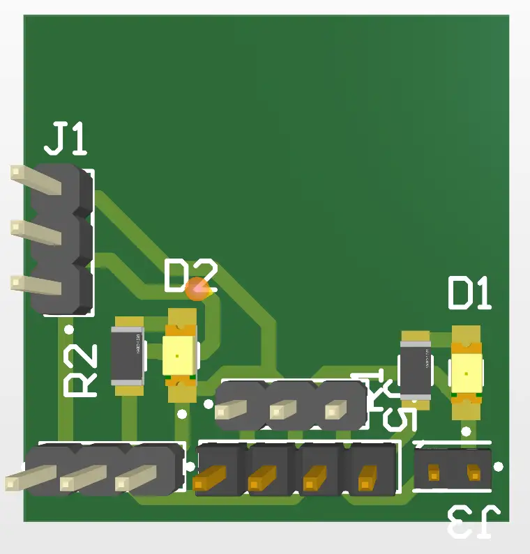
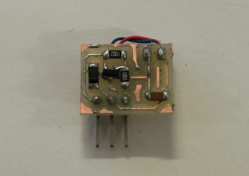
The third PCB is the motor driver board. It is based on the board developed during the Week 10 assignment, but it was redesigned and reduced in size to better fit the final product.
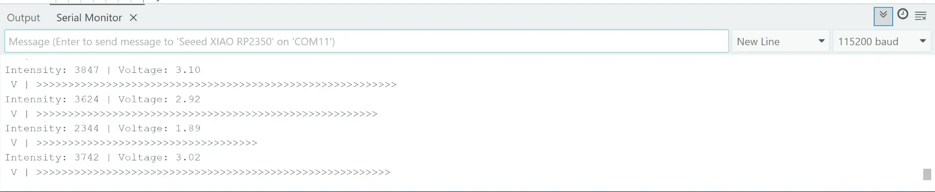
For the input device, I used a microphone module based on the MAX4466. I performed some tests to measure and detect the sound level received by the microphone. For more information about this input device, its operation, and the testing process, refer to my Week 9 documentation.
                    const int micPin = D0;  // Pin of the microphone
                    const float volt = 3.3; // Voltage power of the XIAO

                    void setup() {
                    analogReadResolution(12);      // Reading precision
                    Serial.begin(115200);          // Serial communication
                    while(!Serial);
                    }

                    void loop() {
                    unsigned int sampleWindow = 50; // Use 50 milliseconds to listen for sound
                    unsigned int signalMax = 0;     // Variable to store the highest sound level
                    unsigned int signalMin = 4095;  // Variable to store the lowest sound level

                    unsigned long startMillis = millis(); // Record the exact time we start listening

                    // Collect sound data for 50 milliseconds
                    while (millis() - startMillis < sampleWindow) {
                        int sample = analogRead(micPin);  // Read the current value from the microphone
                        if (sample > signalMax) {         // If current value is higher than our max
                        signalMax = sample;             // Update signalMax
                        }
                        if (sample < signalMin) {         // If current value is lower than our min
                        signalMin = sample;             // Update signalMin
                        }
                    }

                    // Calculate the difference between the loudest and quietest moments
                    int peakToPeak = signalMax - signalMin;

                    // Convert the digital intensity into real Voltage
                    float volts = (peakToPeak * volt) / 4095.0;


                    Serial.print("Intensity: ");       // Intensity
                    Serial.print(peakToPeak);          // Digital value
                    Serial.print(" | Voltage: ");      // Voltage
                    Serial.println(volts);             // Print the voltage
                    Serial.print(" V | ");

                    int numR = map(peakToPeak, 0, 2000, 0, 30);
                    for (int i = 0; i < numR; i++) {
                        Serial.print(">");
                    }

                    Serial.println();

                    delay(50);
                    }
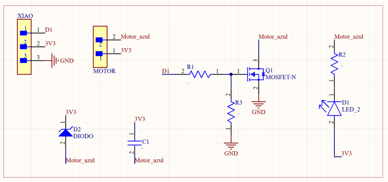
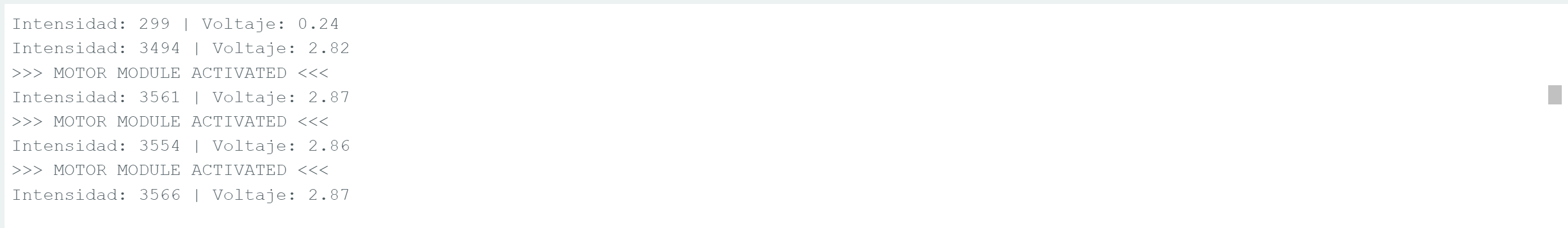
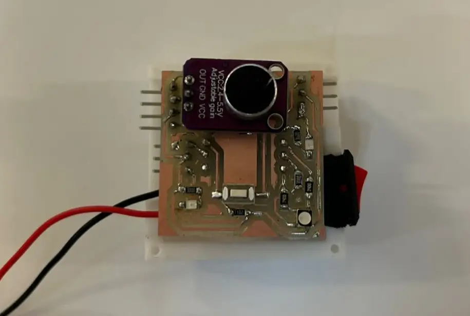
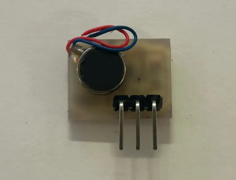
For the output device, I used a vibration motor module. I tested it by activating the motor whenever the microphone detected a sound level above a defined threshold. This allowed the system to convert audio information into haptic feedback. For more information about the development, testing, and fabrication of this board, refer to my Week 10 documentation.
                    // Pin definitions
                    const int micPin = D0;           // Microphone OUT connected to A0
                    const int modulePin = D5;        // Motor Module connected to D5

                    // Settings
                    const float threshold = 2.5;     // Noise limit (Voltage) to trigger the motor
                    const float voltiosReferencia = 3.3;

                    void setup() {
                    analogReadResolution(12);      // 12-bit resolution for RP2350
                    pinMode(modulePin, OUTPUT);    // Set module pin as output

                    digitalWrite(modulePin, LOW);  // Start with motor OFF

                    Serial.begin(115200);
                    while(!Serial);
                    }

                    void loop() {
                    unsigned int sampleWindow = 50; // 50ms window to catch sound waves
                    unsigned int signalMax = 0;
                    unsigned int signalMin = 4095;

                    unsigned long startMillis = millis();

                    // Step 1: Record sound to find Peak-to-Peak amplitude
                    while (millis() - startMillis < sampleWindow) {
                        int sample = analogRead(micPin);
                        if (sample > signalMax) signalMax = sample;
                        if (sample < signalMin) signalMin = sample;
                    }

                    // Step 2: Calculate intensity and real voltage
                    int peakToPeak = signalMax - signalMin;
                    float volts = (peakToPeak * voltiosReferencia) / 4095.0;

                    Serial.print("Intensity: ");
                    Serial.print(peakToPeak);
                    Serial.print(" | Voltage: ");
                    Serial.println(volts);

                    // Step 3: Logic to activate the External Module
                    if (volts >= threshold) {
                        // If sound is LOUD: Turn ON the module
                        digitalWrite(ledPin, HIGH);
                        digitalWrite(modulePin, HIGH);

                        Serial.println(">>> MOTOR MODULE ACTIVATED <<<");
                        delay(400); // Keep vibrating for 400ms
                    }
                    else {
                        // If sound is QUIET: Turn OFF everything
                        digitalWrite(ledPin, LOW);
                        digitalWrite(modulePin, LOW);
                    }

                    delay(10);
                    }
Once the designs for my final PCBs were completed, I milled and soldered them to begin the integration of the entire system. This allowed me to connect all the electronic components and start testing the wearable as a complete device. If you would like to learn more about the PCB fabrication process, refer to my Week 8 documentation. Here are some examples of the final assembled boards.
| Component | Pin Label | GPIO | Type | Description |
|---|---|---|---|---|
| Microphone Left (MAX4466) | A1 | GPIO1 | INPUT | Analog audio signal – left ear |
| Microphone Right (MAX4466) | A0 | GPIO0 | INPUT | Analog audio signal – right ear |
| Vibration Motor Left | D2 | GPIO4 | OUTPUT | Haptic motor – left side |
| Vibration Motor Right | D8 | GPIO19 | OUTPUT | Haptic motor – right side |
| LED 1 | D3 | GPIO5 | OUTPUT | Visual indicator – left channel |
| LED 2 | D10 | GPIO21 | OUTPUT | Visual indicator – right channel |
| RGB LED – Red | D6 | GPIO16 | OUTPUT | Walk Mode indicator (red) |
| RGB LED – Green | D4 | GPIO6 | OUTPUT | Not used in current version |
| RGB LED – Blue | D5 | GPIO23 | OUTPUT | Music Mode indicator (blue) |
This sketch was used to verify that both MAX4466 microphones were working correctly and that the direction logic (LEFT / RIGHT / CENTER / SILENCE) responded accurately to real sounds. It reads both analog microphones, calculates an RMS level calibrated in dB, and activates the corresponding vibration motor with a 2-second sustained timer so that short sounds are felt clearly even if the vibration motor has a slow response.
                    #define MIC_LEFT    A1          // left microphone analog pin
                    #define MIC_RIGHT   A0          // right microphone analog pin
                    #define MOTOR_LEFT  D2          // left vibration motor digital pin
                    #define MOTOR_RIGHT D8          // right vibration motor digital pin

                    #define SAMPLES      100         // number of ADC samples per reading for stability
                    #define DB_SILENCIO  45          // dB floor — ambient noise level in silence
                    #define DB_MAXIMO    80          // dB ceiling — maximum expected loud sound
                    #define THRESHOLD    50          // 0–100 level required to activate a motor
                    #define DIFF_UMBRAL  12          // minimum level difference to decide LEFT vs RIGHT
                    #define VIB_DURACION 2000        // vibration sustain time in milliseconds after detection

                    int readMic(int pin) {           // reads one microphone and returns a 0–100 level
                    long suma = 0;
                    for (int i = 0; i < SAMPLES; i++) {
                        suma += analogRead(pin);     // accumulate raw ADC values (0–4095)
                        delayMicroseconds(200);      // small delay between samples for stability
                    }
                    int dc = suma / SAMPLES;       // calculate DC offset (average resting value)

                    double sumSq = 0;
                    for (int i = 0; i < SAMPLES; i++) {
                        float c = analogRead(pin) - dc;  // center sample around zero (remove DC)
                        sumSq += c * c;               // accumulate squares for RMS calculation
                        delayMicroseconds(200);
                    }
                    int rms = (int)sqrt(sumSq / SAMPLES);  // root mean square = signal energy

                    // convert RMS to approximate dB using 12-bit ADC full scale (4096)
                    float dB = (rms > 0) ? 20.0f * log10f((float)rms / 4096.0f) + 94.0f : DB_SILENCIO;
                    dB = constrain(dB, 0, 120);

                    // map calibrated dB range to 0–100 scale for easy threshold comparison
                    return constrain(map((int)dB, DB_SILENCIO, DB_MAXIMO, 0, 100), 0, 100);
                    }

                    // independent timers per motor — allows each side to sustain separately
                    unsigned long timerIzq = 0;
                    unsigned long timerDer = 0;

                    void setup() {
                    Serial.begin(115200);
                    analogReadResolution(12);         // set ADC to 12-bit resolution (0–4095)
                    analogSetAttenuation(ADC_11db);    // full 0–3.3V input range
                    pinMode(MOTOR_LEFT,  OUTPUT);
                    pinMode(MOTOR_RIGHT, OUTPUT);
                    digitalWrite(MOTOR_LEFT,  LOW);    // ensure motors start off
                    digitalWrite(MOTOR_RIGHT, LOW);
                    }

                    void loop() {
                    int left  = readMic(MIC_LEFT);    // read calibrated level from left mic
                    int right = readMic(MIC_RIGHT);   // read calibrated level from right mic

                    bool leftLoud  = left  >= THRESHOLD;   // true if left side exceeds threshold
                    bool rightLoud = right >= THRESHOLD;   // true if right side exceeds threshold
                    int  diff      = abs(left - right);    // absolute difference between channels
                    unsigned long ahora = millis();       // current timestamp in milliseconds

                    String dir = "SILENCIO";             // default direction state

                    if (leftLoud || rightLoud) {
                        if (!leftLoud && rightLoud) {
                        dir = "DERECHA";
                        timerDer = ahora;                  // restart right motor timer
                        } else if (leftLoud && !rightLoud) {
                        dir = "IZQUIERDA";
                        timerIzq = ahora;                  // restart left motor timer
                        } else if (diff <= DIFF_UMBRAL) {
                        dir = "CENTRO";
                        timerIzq = timerDer = ahora;       // restart both timers — sound is centered
                        } else if (left > right) {
                        dir = "IZQUIERDA";
                        timerIzq = ahora;
                        } else {
                        dir = "DERECHA";
                        timerDer = ahora;
                        }
                    }

                    // motor stays ON as long as timer has not expired (2 seconds)
                    bool encenderIzq = (ahora - timerIzq) < VIB_DURACION;
                    bool encenderDer = (ahora - timerDer) < VIB_DURACION;

                    digitalWrite(MOTOR_LEFT,  encenderIzq ? HIGH : LOW);
                    digitalWrite(MOTOR_RIGHT, encenderDer ? HIGH : LOW);

                    // print live serial monitor output with visual bars and remaining timer
                    int restIzq = max(0, (int)(VIB_DURACION - (ahora - timerIzq)));
                    int restDer = max(0, (int)(VIB_DURACION - (ahora - timerDer)));
                    Serial.printf("IZQ %3d [%-20s]  DER %3d [%-20s]  → %-10s  MOT:[%s %dms][%s %dms]\n",
                        left,  String("#").substring(0, map(left,  0, 100, 0, 20)).c_str(),
                        right, String("#").substring(0, map(right, 0, 100, 0, 20)).c_str(),
                        dir.c_str(),
                        encenderIzq ? "ON " : "OFF", restIzq,
                        encenderDer ? "ON " : "OFF", restDer);
                    }
This sketch tests the Music Mode behavior. Both motors and both LEDs follow the rhythm of music in real time. Instead of direction logic, it uses the maximum value between both microphones so that neither side can silence the other. An exponential smoothing filter makes the vibration feel fluid rather than choppy, mimicking a natural bass response.
                        #define MIC_LEFT     A1         // left microphone analog pin
                        #define MIC_RIGHT    A0         // right microphone analog pin
                        #define MOTOR_LEFT   D2         // left vibration motor
                        #define MOTOR_RIGHT  D8         // right vibration motor
                        #define LED_1        D3         // first LED indicator
                        #define LED_2        D10        // second LED indicator

                        #define SAMPLES      60         // fewer samples = faster response = better rhythm tracking
                        #define DB_SILENCIO  45         // dB floor for calibration (ambient noise level)
                        #define DB_MAXIMO    80         // dB ceiling for calibration (loud sound reference)
                        #define THRESHOLD    25         // lower than Walk Mode — catches softer musical beats
                        #define SMOOTH       0.4f       // smoothing coefficient: 0 = very smooth, 1 = instant

                        int readMic(int pin) {          // returns calibrated 0–100 level from one microphone
                        long suma = 0;
                        for (int i = 0; i < SAMPLES; i++) {
                            suma += analogRead(pin);
                            delayMicroseconds(100);     // shorter delay for faster sampling in music mode
                        }
                        int dc = suma / SAMPLES;      // average = DC offset of the microphone signal

                        double sumSq = 0;
                        for (int i = 0; i < SAMPLES; i++) {
                            float c = analogRead(pin) - dc;  // remove DC component, center at zero
                            sumSq += c * c;
                            delayMicroseconds(100);
                        }
                        int rms = (int)sqrt(sumSq / SAMPLES);   // RMS value represents signal energy
                        float dB = (rms > 0) ? 20.0f * log10f((float)rms / 4096.0f) + 94.0f : DB_SILENCIO;
                        dB = constrain(dB, 0, 120);
                        return constrain(map((int)dB, DB_SILENCIO, DB_MAXIMO, 0, 100), 0, 100);
                        }

                        float smoothVal = 0;           // persistent smoothed value across loop iterations

                        void setup() {
                        Serial.begin(115200);
                        analogReadResolution(12);
                        analogSetAttenuation(ADC_11db);
                        pinMode(MOTOR_LEFT,  OUTPUT);
                        pinMode(MOTOR_RIGHT, OUTPUT);
                        pinMode(LED_1,       OUTPUT);
                        pinMode(LED_2,       OUTPUT);
                        digitalWrite(MOTOR_LEFT,  LOW);
                        digitalWrite(MOTOR_RIGHT, LOW);
                        digitalWrite(LED_1,       LOW);
                        digitalWrite(LED_2,       LOW);
                        }

                        void loop() {
                        int rawLeft  = readMic(MIC_LEFT);   // left channel current level
                        int rawRight = readMic(MIC_RIGHT);  // right channel current level

                        // use the louder channel — prevents one quiet mic from blocking the beat
                        int rawMax = max(rawLeft, rawRight);

                        // exponential smoothing: blends new reading with previous value
                        // formula: smooth = (alpha * new) + ((1 - alpha) * previous)
                        smoothVal = (SMOOTH * rawMax) + ((1.0f - SMOOTH) * smoothVal);
                        int nivel = (int)smoothVal;          // integer smoothed level for threshold comparison

                        bool activo = nivel >= THRESHOLD;   // true when beat is detected above threshold

                        // activate or deactivate both motors and LEDs simultaneously
                        digitalWrite(MOTOR_LEFT,  activo ? HIGH : LOW);
                        digitalWrite(MOTOR_RIGHT, activo ? HIGH : LOW);
                        digitalWrite(LED_1,       activo ? HIGH : LOW);
                        digitalWrite(LED_2,       activo ? HIGH : LOW);

                        // serial monitor: show both raw levels, smoothed level, and activation bar
                        int bar = map(nivel, 0, 100, 0, 30);
                        Serial.printf("IZQ:%3d  DER:%3d  MAX:%3d  [", rawLeft, rawRight, nivel);
                        for (int i = 0; i < 30; i++) {
                            if      (i < bar && nivel > 70) Serial.print('!');  // loud beat
                            else if (i < bar)               Serial.print('#');  // normal beat
                            else                            Serial.print(' ');  // silence
                        }
                        Serial.printf("]  %s\n", activo ? "ON " : "---");
                        }
For the main structure of the headband, I designed an adjustable fabric band to improve user comfort. The band was assembled using a sewing machine, allowing it to fit different head sizes.
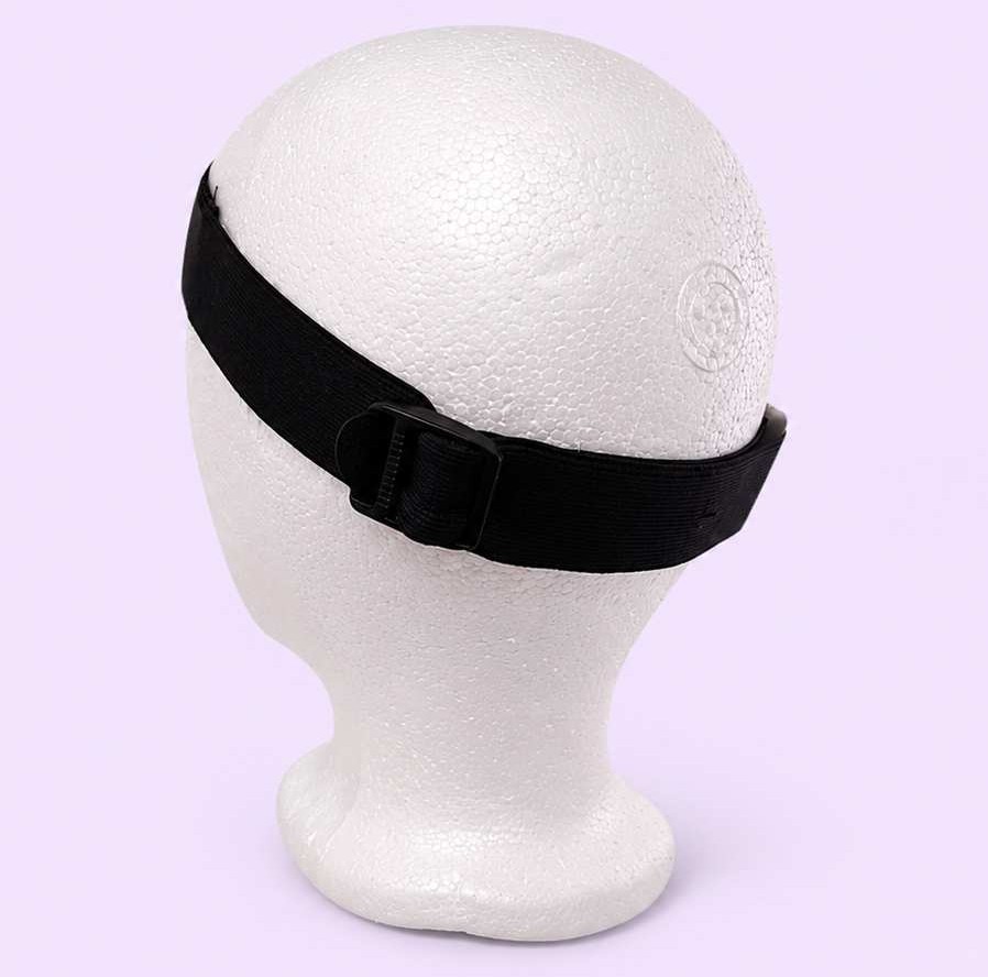
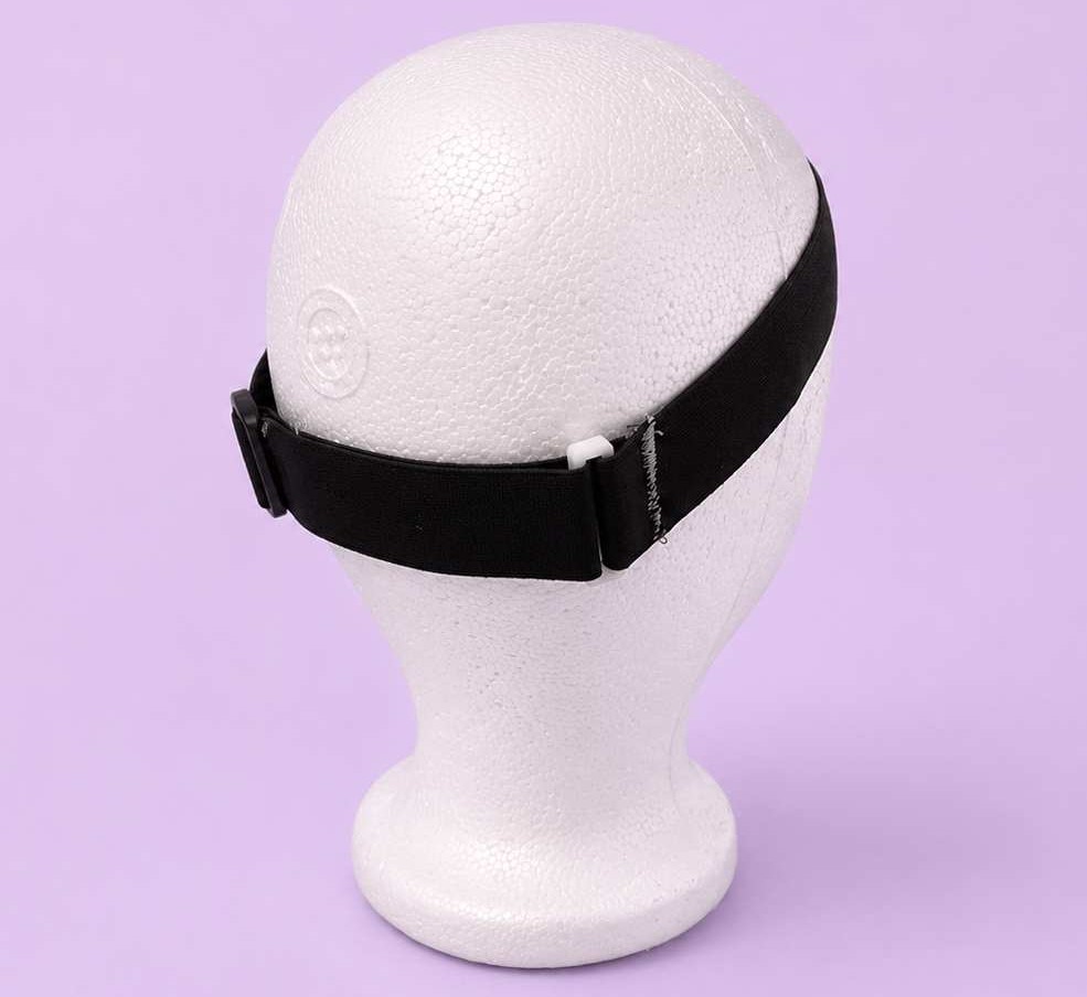
To attach the 3D-printed enclosures, I also designed a custom mounting piece, which was hand-sewn onto the fabric band to create a secure connection between the textile structure and the electronic components.
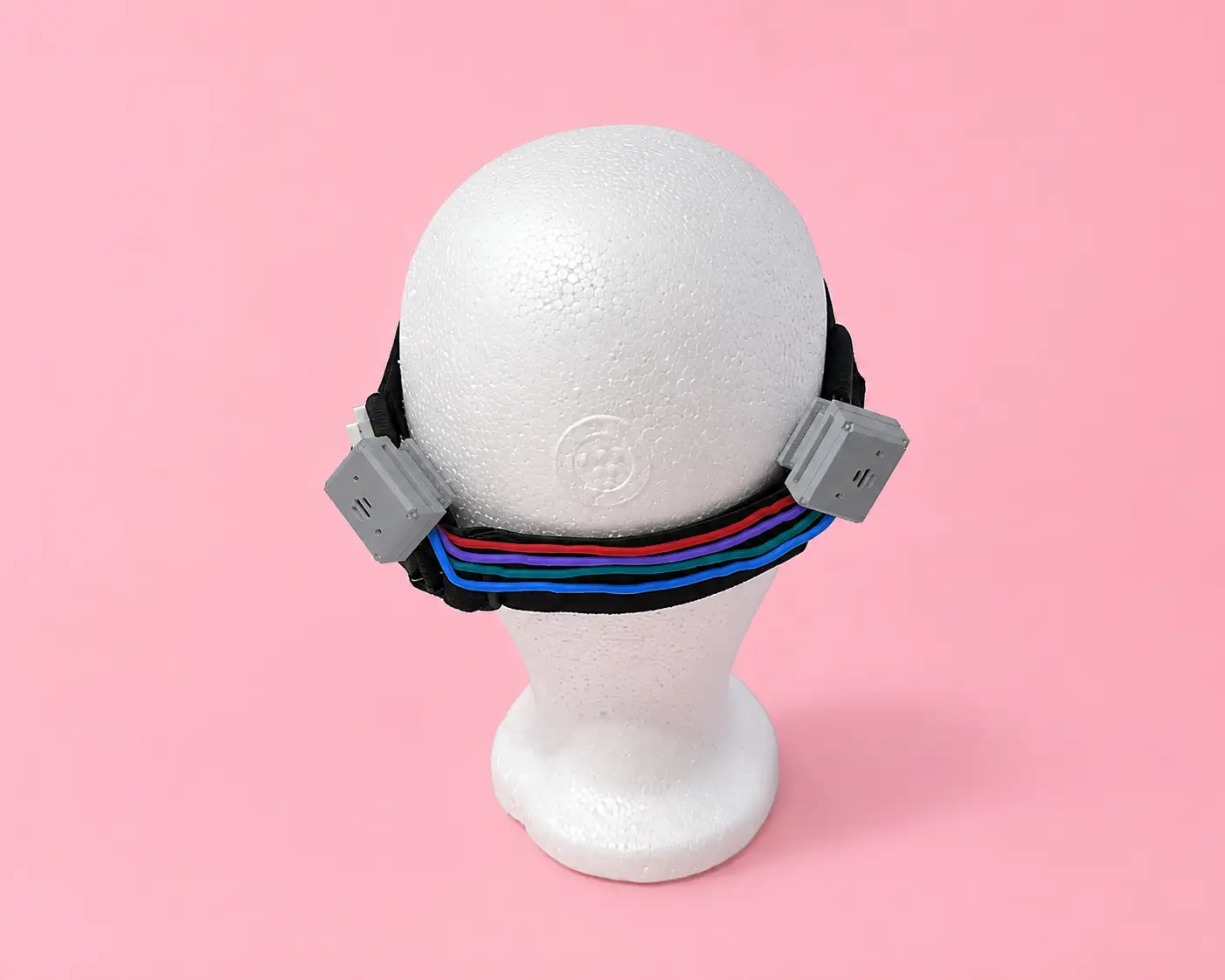
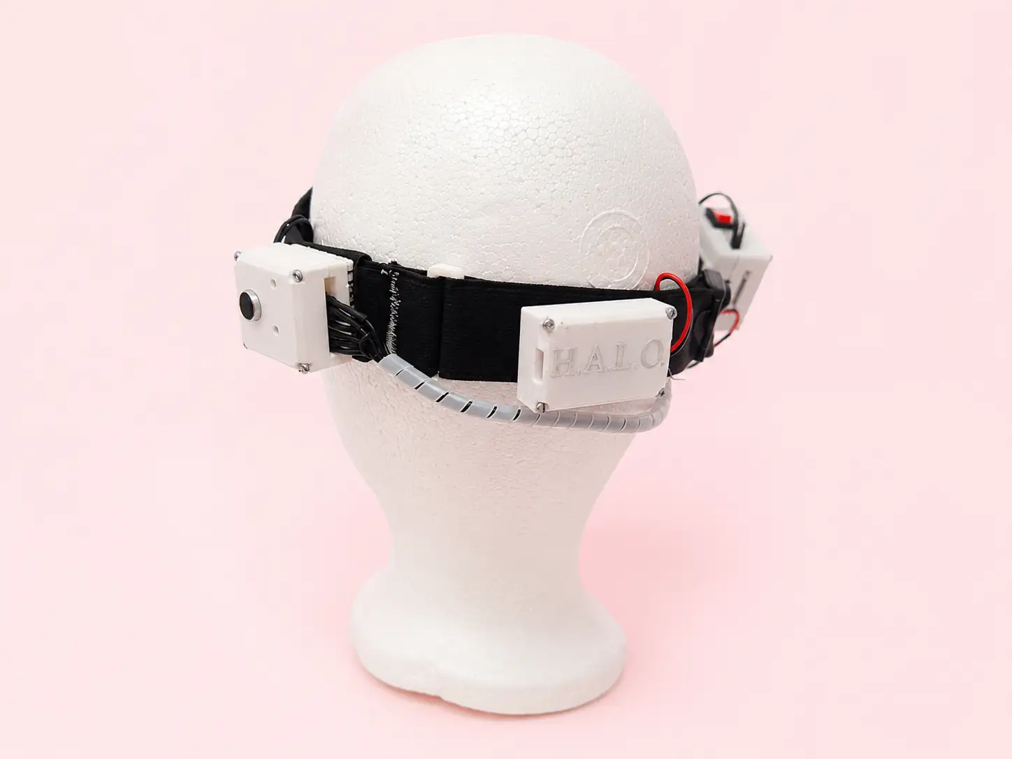
The electronic enclosures are mounted on both sides of the headband, while the connecting wires are routed behind the head. This arrangement helps distribute the components more comfortably and reduces interference during normal use.
The following images show the proposed arrangement of the electronic components and cable routing within the wearable system. The connecting wires will be covered with a braided cable sleeve to keep them organized and prevent tangling.
This is the final arrangement of the headband with all the integrated components.
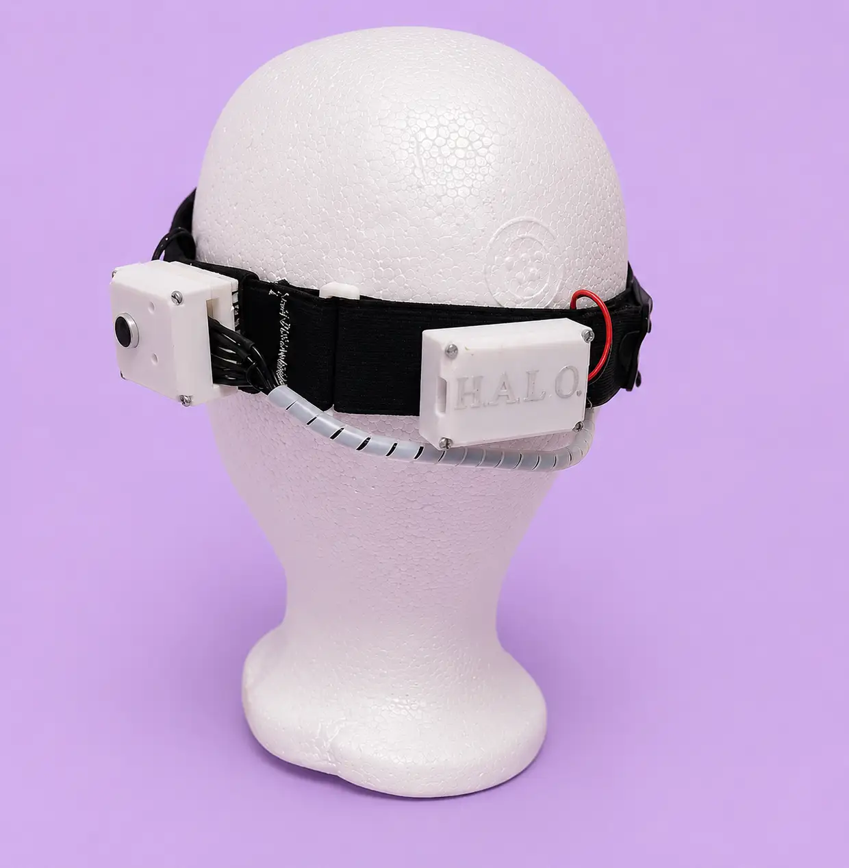
For the assembly process, I enclosed the PCBs inside their respective 3D-printed enclosures, leaving the microphone and cable connections accessible through the designated openings. Once assembled, I tested how the enclosures fit onto the headband and verified that all components could be securely mounted while maintaining the intended wearable design.
I will mainly focus on an open-source hardware approach. All technical documentation, 3D models, PCB design and fabrication files, and source code will be available in my Fab Academy repository so that anyone can replicate, learn from, or modify their own version of the Haptic Auditory Location Orientator. Sharing the project openly will allow others to improve the design and adapt it to their own needs.
This is the license I selected for my project. After reviewing the available Creative Commons options, I chose the one that best matches how I want HALO to be shared and used.
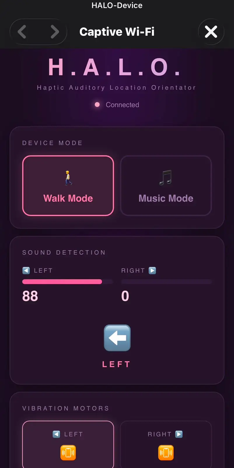
The ESP32-C6 creates its own WiFi network (HALO-Device) and serves an HTML interface through a Captive Portal. When a phone connects to the network, the browser automatically opens the control page without requiring the user to type an IP address or URL. This makes the device easier and more intuitive to use.
The interface communicates with the ESP32-C6 in real time using WebSocket communication on port 81, allowing instant updates between the wearable and the user interface. Through the interface, the user can switch between Walk Mode and Music Mode, monitor the current status of the system, and adjust settings without directly interacting with the hardware. The RGB LED provides visual feedback by changing color according to the selected mode, making it easy to identify the active operating state. This interface serves as the main point of interaction between the user and HALO, simplifying control, configuration, and future calibration features.
#include <WiFi.h> // WiFi Access Point functionality
#include <WebServer.h> // HTTP server to serve the HTML page
#include <WebSocketsServer.h> // WebSocket server for real-time communication
#include <ArduinoJson.h> // JSON serialization/deserialization
#include <DNSServer.h> // DNS server for captive portal redirect
#include <math.h> // sqrt(), log10f() for RMS and dB calculation
// ── Pin definitions ──────────────────────────────────────────────
#define MIC_LEFT A1 // left MAX4466 microphone analog output
#define MIC_RIGHT A0 // right MAX4466 microphone analog output
#define MOTOR_LEFT D2 // left coin vibration motor
#define MOTOR_RIGHT D8 // right coin vibration motor
#define LED_1 D3 // LED indicator — left channel activity
#define LED_2 D10 // LED indicator — right channel activity
#define LED_R D6 // RGB LED red channel (Walk Mode color)
#define LED_G D4 // RGB LED green channel (unused in current modes)
#define LED_B D5 // RGB LED blue channel (Music Mode color)
// ── Microphone calibration ───────────────────────────────────────
#define DB_SILENCIO 55 // raised from 45 to ignore vibration motor noise
#define DB_MAXIMO 80 // dB level of a loud voice close to the microphone
#define DIFF_UMBRAL 12 // max level difference to classify as CENTER
#define SAMPLES 80 // more samples = more stable reading, fewer false triggers
// ── Access Point credentials ─────────────────────────────────────
const char* AP_SSID = "HALO-Device"; // WiFi network name broadcast by the device
const char* AP_PASS = "halo1234"; // WiFi password (minimum 8 characters)
// ── Server instances ─────────────────────────────────────────────
WebServer server(80); // HTTP server on port 80 — serves the HTML page
WebSocketsServer ws(81); // WebSocket server on port 81 — real-time data
DNSServer dns; // DNS server — redirects all domains to 192.168.4.1
// ── Runtime state ────────────────────────────────────────────────
String currentMode = "walk"; // active mode: "walk" or "music"
int threshold = 60; // 0–100 activation level (raised for voice-only detection)
String pattern = "long";// vibration pattern: "long" or "continuous"
float smoothVal = 0; // persistent smoothed value for music mode
unsigned long lastVib = 0; // timestamp of last vibration trigger
// ── readMic() ────────────────────────────────────────────────────
// Reads one MAX4466 microphone and returns a 0–100 calibrated level.
// Uses RMS calculation over multiple samples to estimate dB level,
// then maps the calibrated dB range to a 0–100 scale.
int readMic(int pin) {
long suma = 0;
for (int i = 0; i < SAMPLES; i++) {
suma += analogRead(pin);
delayMicroseconds(150); // pacing between reads for stable ADC
}
int dc = suma / SAMPLES; // DC offset: midpoint of the microphone signal
double sumSq = 0;
for (int i = 0; i < SAMPLES; i++) {
float c = analogRead(pin) - dc; // AC component only (actual sound energy)
sumSq += c * c;
delayMicroseconds(150);
}
int rms = (int)sqrt(sumSq / SAMPLES);
float dB = (rms > 0) ? 20.0f * log10f((float)rms / 4096.0f) + 94.0f : DB_SILENCIO;
dB = constrain(dB, 0, 120);
return constrain(map((int)dB, DB_SILENCIO, DB_MAXIMO, 0, 100), 0, 100);
}
// ── setRGB() ─────────────────────────────────────────────────────
// Controls the RGB LED. Common cathode: LOW = ON, HIGH = OFF.
// Called whenever the mode changes to reflect it visually.
void setRGB(bool r, bool g, bool b) {
digitalWrite(LED_R, r ? LOW : HIGH); // red on when r = true
digitalWrite(LED_G, g ? LOW : HIGH); // green on when g = true
digitalWrite(LED_B, b ? LOW : HIGH); // blue on when b = true
}
void updateLED() {
if (currentMode == "walk") setRGB(true, false, false); // red = walk
else if (currentMode == "music") setRGB(false, false, true); // blue = music
}
// ── vibrateMotor() ───────────────────────────────────────────────
// Triggers a motor with the selected pattern.
// "long" = single 400ms pulse then off
// "continuous" = pin stays HIGH (managed by loop)
void vibrateMotor(int pin, String pat) {
if (pat == "long") {
digitalWrite(pin, HIGH); delay(400); // 400ms sustained pulse
digitalWrite(pin, LOW); // turn off after pulse
} else {
digitalWrite(pin, HIGH); // continuous: stays on until loop turns it off
}
}
// ── onWSEvent() ──────────────────────────────────────────────────
// Called by WebSocketsServer when a client sends a message.
// Parses JSON config from the web interface and updates global state.
void onWSEvent(uint8_t num, WStype_t type, uint8_t* payload, size_t length) {
if (type == WStype_TEXT) {
StaticJsonDocument<128> doc;
if (deserializeJson(doc, payload) == DeserializationError::Ok) {
if (doc.containsKey("mode")) currentMode = doc["mode"].as<String>(); // update mode
if (doc.containsKey("threshold")) threshold = doc["threshold"]; // update threshold
if (doc.containsKey("pattern")) pattern = doc["pattern"].as<String>(); // update pattern
updateLED(); // reflect mode on RGB
}
}
}
// ── setup() ──────────────────────────────────────────────────────
// Initializes all hardware, starts the WiFi Access Point,
// DNS server (captive portal), HTTP server, and WebSocket server.
void setup() {
Serial.begin(115200);
// configure all output pins
pinMode(MOTOR_LEFT, OUTPUT);
pinMode(MOTOR_RIGHT, OUTPUT);
pinMode(LED_1, OUTPUT);
pinMode(LED_2, OUTPUT);
pinMode(LED_R, OUTPUT);
pinMode(LED_G, OUTPUT);
pinMode(LED_B, OUTPUT);
digitalWrite(MOTOR_LEFT, LOW); // motors off at boot
digitalWrite(MOTOR_RIGHT, LOW);
digitalWrite(LED_1, LOW); // LEDs off at boot
digitalWrite(LED_2, LOW);
updateLED(); // set RGB to Walk Mode red
analogReadResolution(12); // 12-bit ADC: values 0–4095
analogSetAttenuation(ADC_11db); // full 0–3.3V ADC input range
WiFi.softAP(AP_SSID, AP_PASS); // create WiFi Access Point
dns.start(53, "*", WiFi.softAPIP()); // DNS on port 53, catch all domains → captive portal
// serve the HTML page at root path
server.on("/", []() { server.send_P(200, "text/html", HTML); });
// redirect all other URLs to root (captive portal behavior)
server.onNotFound([]() {
server.sendHeader("Location", "http://192.168.4.1", true);
server.send(302, "text/plain", "");
});
server.begin(); // start HTTP server
ws.begin(); // start WebSocket server
ws.onEvent(onWSEvent); // register WebSocket event handler
}
// ── loop() ───────────────────────────────────────────────────────
// Main execution loop. Handles network requests, reads microphones
// every 120ms, applies Walk or Music logic, controls motors/LEDs,
// and broadcasts live data to the web interface via WebSocket.
unsigned long lastRead = 0;
void loop() {
dns.processNextRequest(); // process DNS requests for captive portal
server.handleClient(); // process pending HTTP requests
ws.loop(); // process WebSocket messages and keep connections alive
if (millis() - lastRead >= 120) { // read microphones every 120ms (~8 times/sec)
lastRead = millis();
int left = readMic(MIC_LEFT); // calibrated 0–100 level from left mic
int right = readMic(MIC_RIGHT); // calibrated 0–100 level from right mic
bool motorIzq = false; // will left motor activate this cycle?
bool motorDer = false; // will right motor activate this cycle?
bool led1on = false; // will LED 1 turn on this cycle?
bool led2on = false; // will LED 2 turn on this cycle?
String direction = "SILENCE"; // detected direction label for the interface
if (currentMode == "walk") {
// WALK MODE: determine which side the sound comes from
bool leftLoud = left >= threshold; // left mic above threshold?
bool rightLoud = right >= threshold; // right mic above threshold?
int diff = abs(left - right); // difference between channels
if (leftLoud || rightLoud) {
if (!leftLoud && rightLoud) { direction="RIGHT"; motorDer=led2on=true; }
else if (leftLoud && !rightLoud) { direction="LEFT"; motorIzq=led1on=true; }
else if (diff <= DIFF_UMBRAL) { direction="CENTER"; motorIzq=motorDer=led1on=led2on=true; }
else if (left > right) { direction="LEFT"; motorIzq=led1on=true; }
else { direction="RIGHT"; motorDer=led2on=true; }
}
// sustain vibration for 2 seconds after detection
if (motorIzq || motorDer) lastVib = millis();
bool timerActivo = (millis() - lastVib) < 2000; // within 2-second window?
if (!timerActivo) {
digitalWrite(MOTOR_LEFT, LOW); // timer expired — silence motors
digitalWrite(MOTOR_RIGHT, LOW);
digitalWrite(LED_1, LOW); // turn off LEDs
digitalWrite(LED_2, LOW);
} else {
if (pattern == "continuous") {
digitalWrite(MOTOR_LEFT, motorIzq ? HIGH : LOW); // continuous: direct on/off
digitalWrite(MOTOR_RIGHT, motorDer ? HIGH : LOW);
} else {
// long pattern: trigger pulse only at detection moment
if (millis() - lastVib < 100) {
if (motorIzq) vibrateMotor(MOTOR_LEFT, pattern);
if (motorDer) vibrateMotor(MOTOR_RIGHT, pattern);
}
}
digitalWrite(LED_1, led1on ? HIGH : LOW); // light LED matching active side
digitalWrite(LED_2, led2on ? HIGH : LOW);
}
}
else {
// MUSIC MODE: both motors and LEDs follow the beat
int rawMax = max(left, right); // use louder channel to not miss any beat
smoothVal = (0.4f * rawMax) + (0.6f * smoothVal); // exponential smoothing
bool beat = (int)smoothVal >= 25; // activate when smoothed level exceeds 25
digitalWrite(MOTOR_LEFT, beat ? HIGH : LOW); // both motors respond to same beat
digitalWrite(MOTOR_RIGHT, beat ? HIGH : LOW);
digitalWrite(LED_1, beat ? HIGH : LOW); // both LEDs flash with the beat
digitalWrite(LED_2, beat ? HIGH : LOW);
motorIzq = motorDer = led1on = led2on = beat;
}
// broadcast live data to all connected WebSocket clients
StaticJsonDocument<192> doc;
doc["left"] = left; // left mic level 0–100
doc["right"] = right; // right mic level 0–100
doc["direction"] = direction; // "LEFT", "RIGHT", "CENTER", or "SILENCE"
doc["motorLeft"] = motorIzq; // left motor active state
doc["motorRight"] = motorDer; // right motor active state
doc["led1"] = led1on; // LED 1 active state
doc["led2"] = led2on; // LED 2 active state
String out;
serializeJson(doc, out); // convert to JSON string
ws.broadcastTXT(out); // send to all connected browser clients
}
}
You can download the files created and used during this week here:
📄 Files.zip