Computer Controlled Cutting
Group assignments
- Do your lab’s safety training.
- Characterize your lasercutter’s focus, power, speed, rate, kerf, joint clearance and types.
- Document your work to the group work page and reflect on your individual page what you learned.
What is the laser cut technology?
Laser cutting technology uses a concentrated beam of light to cut or engrave materials with high precision. It is suitable for working with metals, plastics, wood, and acrylic, achieving clean, fast, and detailed cuts without physical contact with the workpiece. It is primarily used in manufacturing, design, prototyping, and industrial production.
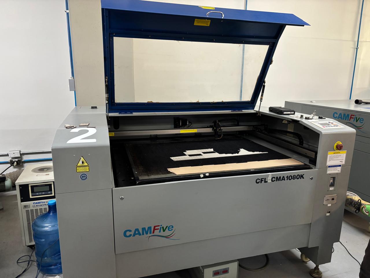
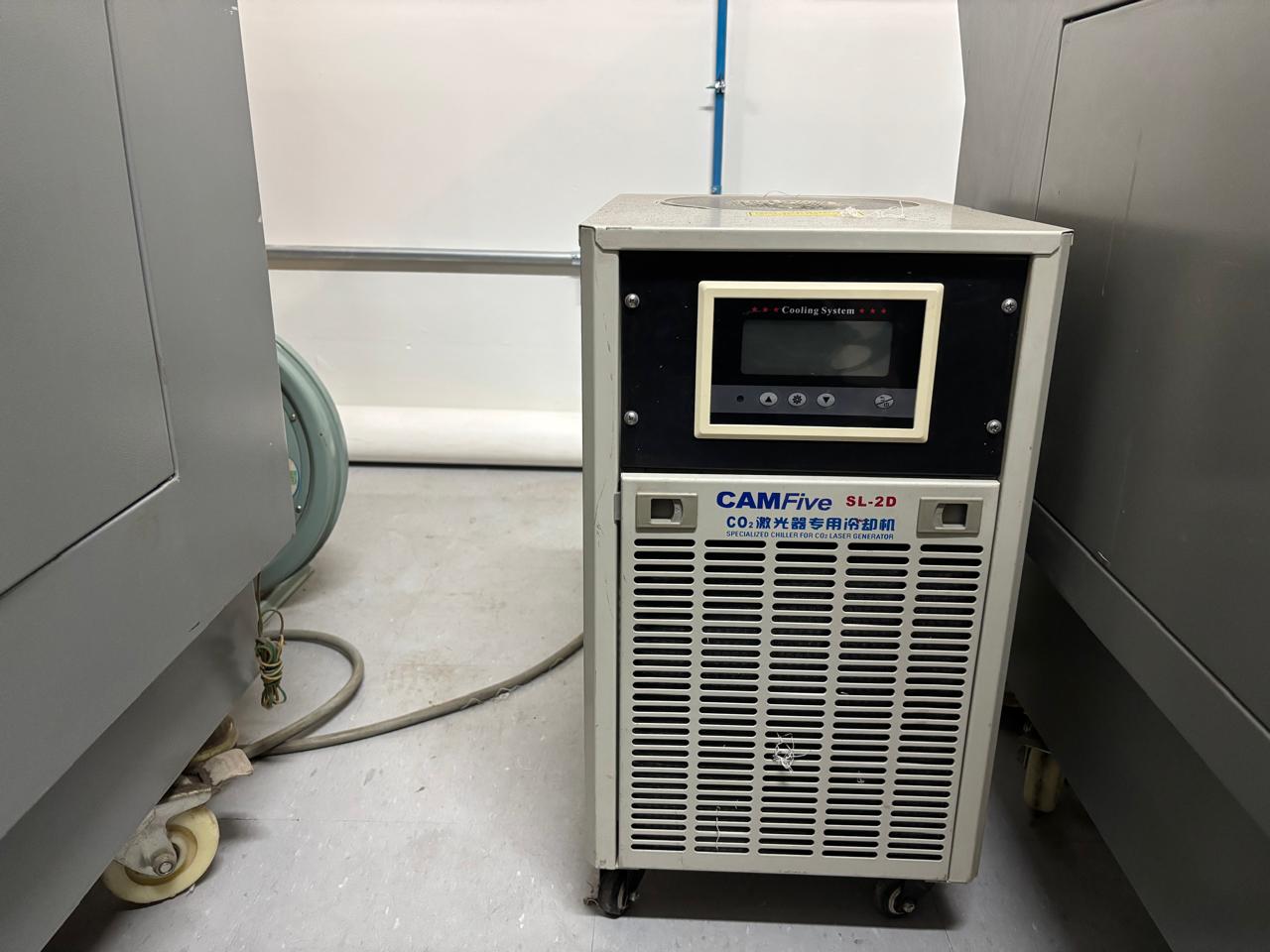
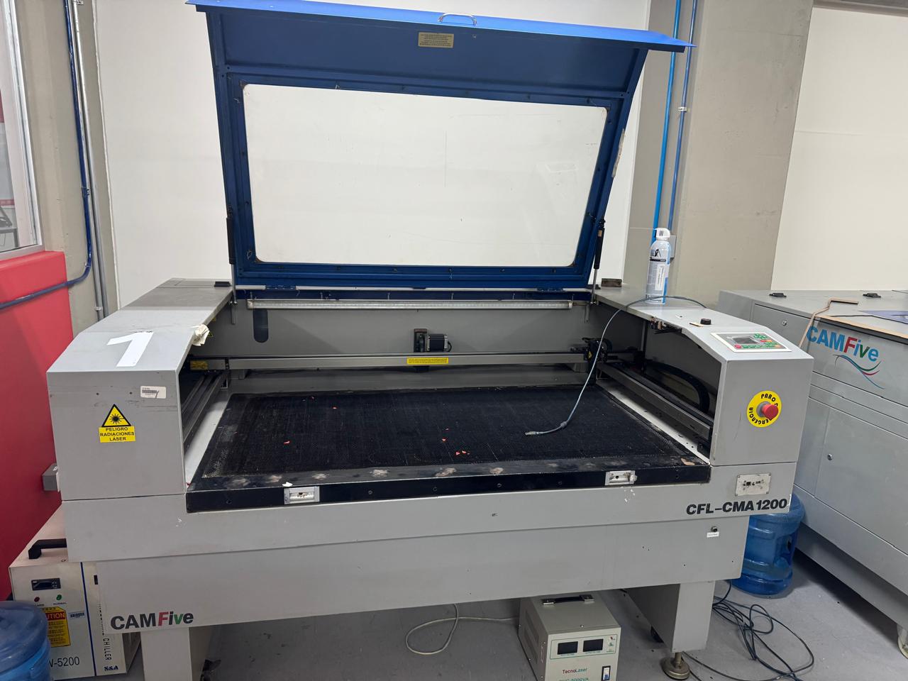
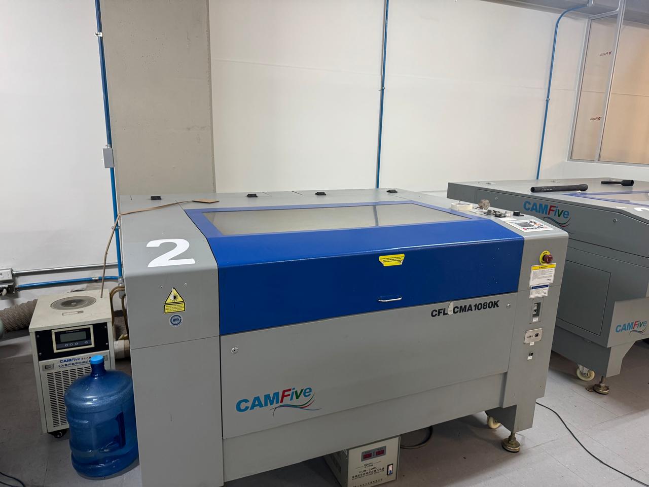
The laser cutters that we have here at Ibero Puebla are 3, this machones were made by CAMFive that utilize cutting-edge CO2 tube technology, this allows the laser for precise and efficient cutting of numerous materials in industry. The CO2 laser operates using a mixture of carbon dioxide gas and is one of the most powerful lasers.
Safety training
- Do not look directly at the laser.
- Do not insert your hand all the way in because the laser is there.
- Do not cut with the door open.
- Ideally, do not cut unfamiliar plastics due to the toxic fumes/gases.
- Lots of smoke mean no cutting; no smoke means cutting.
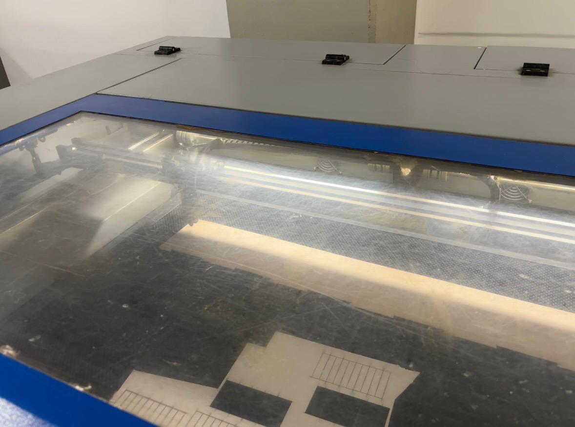
Characterize lasercutter's
CFL-CMA1200
- Work area: 1.20 x 0.60 meters
- Work table: Honeycomb
- Accessory: None
- Cutting speed: 0–36,000 (min/mm)
- Engraving speed: 0-64000 (min/mm)
- Power: 100 Watts
- Cutting thickness: 0–25 mm
- Resolution: Up to 4000 DPI (typically between 600 DPI and 2000 DPI)
- Motion accuracy: None
CFL-CMA1080K
- Work area: 1.00 x 0.80 meters
- Work table: Honeycomb or rod
- Accessory: Double Tube
- Cutting speed: 0–36,000 (min/mm)
- Engraving speed: 0-64000 (min/mm)
- Power: 100 Watts
- Cutting thickness: 0–25 mm
- Resolution: Up to 4000 DPI (typically between 600 DPI and 2000 DPI)
- Motion accuracy: 0.01 mm
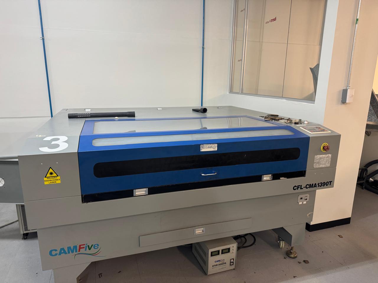
CFL-CMA 1309T
- Work area: 1.30 x 0.90 meters
- Work table: Honeycomb
- Accessory: Double Tube
- Cutting speed: 0–36,000 (min/mm)
- Engraving speed: 0-64000 (min/mm)
- Power: 100 Watts
- Cutting thickness: 0–25 mm
- Resolution: Up to 4000 DPI (typically between 600 DPI and 2000 DPI)
- Motion accuracy: 0.01 mm
Materials compatible with the laser cutters
Cutting
| Natural wood | Edges may burn; sanding is usually needed. |
| MDF | Produces a lot of smoke and odor; good ventilation is required. |
| Plywood | Internal glue layers may affect cut quality. |
| Acrylic (PMMA) | Produces glossy edges; ideal for signs and display parts. |
| Natural leather | May shrink if power is too high. |
| Synthetic leather (PVC-free) | Make sure it does not contain chlorine. |
| Fabric / Textiles | Burns easily; use low power and high speed. |
| Paper | Fire risk; never leave the machine unattended. |
| Cardboard | Can warp due to heat; test first. |
| Cork | Tends to char; use multiple light passes. |
| Soft rubber (chlorine-free) | Can melt with high power. |
| EVA foam | Works well for crafts; avoid overheating. |
| PET (some types) | May melt; not all PET is laser-safe. |
| Polypropylene (PP)/td> | Hard to cut cleanly; testing is required. |
Engraving
| Glass | Using wet paper or spray improves contrast. |
| Ceramic | Only surface marking; no deep engraving. |
| Tile | Works best on glazed surfaces. |
| Stone (granite, marble) | Produces light-colored surface engraving. |
| Marble | Creates clear, decorative markings. |
| Granite | May require multiple passes for good contrast. |
| Stainless steel (uncoated) | Only very light marking; cannot be cut. |
| Aluminum (untreated) | Needs marking spray for good results. |
| Anodized aluminum | Laser removes anodizing and leaves visible marks. |
| Brass | Weak engraving; best with special coatings. |
| Fiberglass | Produces hazardous dust; use protection. |
Focus
Focus refers to the distance between the laser lens and the surface of the material where the smallest focal point converges. This distance is important because laser cutting operates based on energy density. By ensuring an appropriate focus distance, a minimum beam diameter is achieved, resulting in a cleaner, straighter, and more precise cut. A focus distance of 5 mm is recommended.
Proper focusing is essential, as a focus that is too low can cause excessive burning of the material, while a focus that is too high may prevent the material from being cut correctly.
Rate
Rate refers to the number of times per second that the laser emits energy in pulses rather than as a continuous beam. Its units are Hz or PPI. This parameter operates by rapidly turning the laser on and off while it is moving. A high-frequency rate produces closely spaced pulses, whereas a low-frequency rate results in pulses that are more widely spaced.
High-frequency rates are commonly used to achieve smoother and more continuous cuts with polished edges. In contrast, low-frequency rates are used for more aggressive or perforating cuts, typically applied to thick materials such as wood or dense substrates.
Speed
What is it?
It is the intensity of the energy emitted by the laser tube, which must raise the material's temperature above its boiling point almost instantaneously.
There are two parameters to set power: minimum and maximum. Both help us determine the thickness of the piece that can be cut through. With appropriate values, Heat Affected Zones (HAZ) should not be visible; these are avoided by using high power with fast speeds. Additionally, there should be a difference of between 10% and 20% between the two.
It is what decides the time the beam interacts with the surface of the material. It indicates how fast the laser head moves over the workspace, which directly affects:
- Aesthetics: A very low (slow) speed over-carbonizes the edge or melts it (as in the case of acrylic). If it were optimal, it should leave a cinnamon color or a nearly transparent finish (in the case of acrylic).
- Kerf (width of the cut):At a slow speed, the kerf is wider; while at a fast speed, the kerf is finer and more precise.
| To evaluate | Maximum Power | Minimum Power |
| What is it | It is the upper output limit of the laser tube (CO2) or diode/fiber. It determines the maximum thickness you can cut through. | It is the lower output limit of the laser tube (CO2) or diode/fiber. |
| When is it used | Straight sections and high-speed movement. | It mainly controls how the laser behaves in curves and corners, as it must slow down almost to zero to change direction and then accelerate again. This prevents the "node burning" effect, where too much energy would be deposited at that point. |
| Objective | To cut through the thickness of the material. | To maintain cutting uniformity. |
| If it is too high | It burns the material or causes fires. | It melts the corners and loses detail. |
| If it is too low. | The laser fails to cut through the material. | The laser turns off in curves, and the cut remains incomplete. |
General Summary
| Power (in %) | Speed | |
| The higher | The laser can cut through thicker materials. | A more superficial cut or a fainter engraving is obtained. |
| The lower | Superficial engravings or work on very thin materials can be achieved; otherwise, they could melt or catch fire. Superficial engravings or work on very thin materials can be achieved; otherwise, they could melt or catch fire. | The depth of penetration increases (necessary for clean cuts in thick materials). |
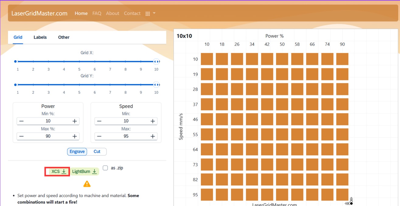
Speed vs Power (comparative examples)
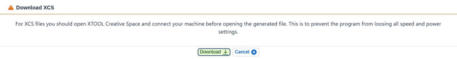
A test was conducted to determine the machine's parameters. To do this, a template from the LaserGridMaster website was used, which provides a comparison between 'Power' and 'Speed'. Subsequently, to save the file and ensure the laser parameters are preserved, the green 'XCS' button is clicked.
To save the document in XCS, click on the 'Download' option.
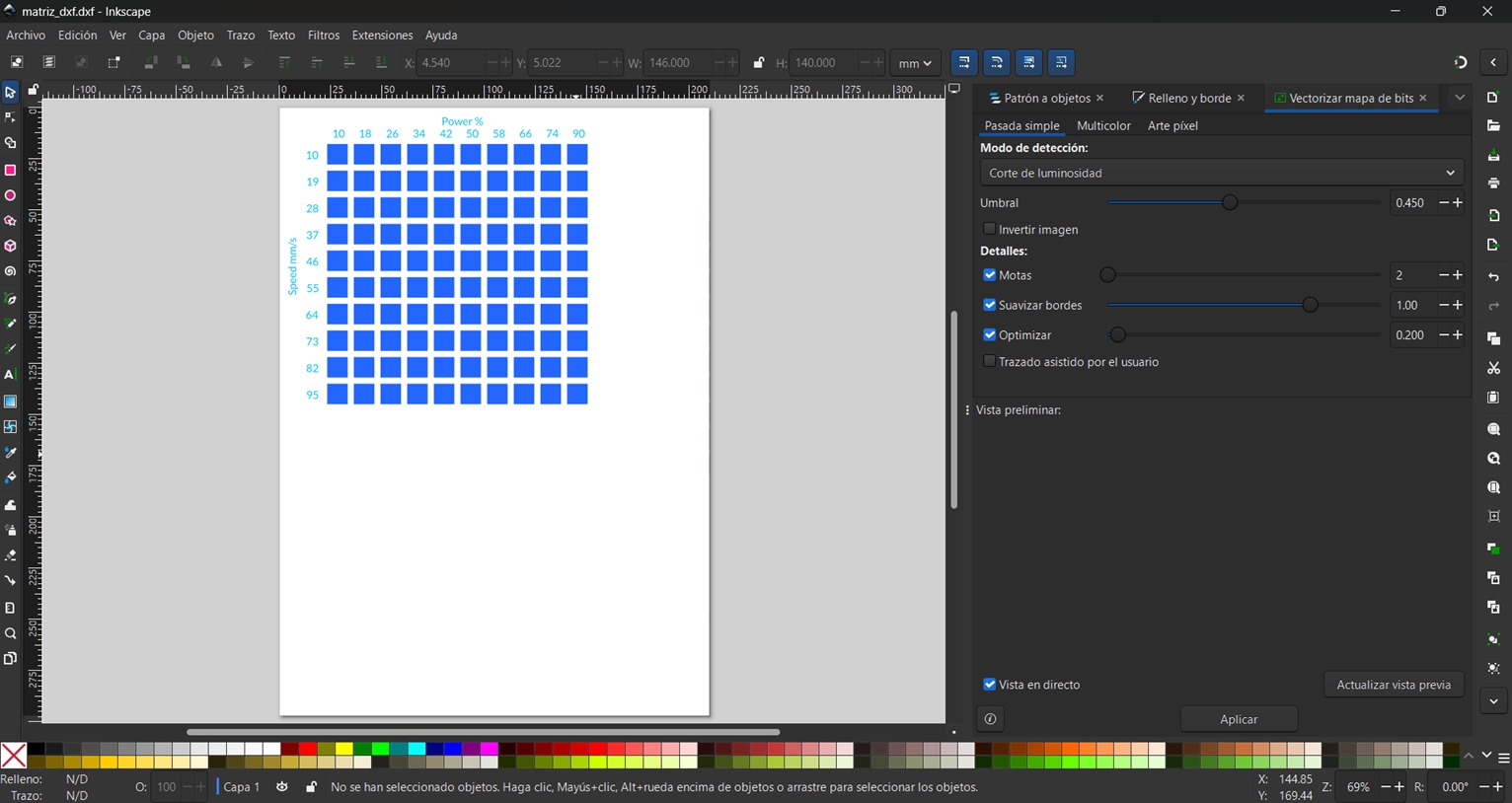
Then, I imported it into the xTool program xTool Studio to save it as an SVG.
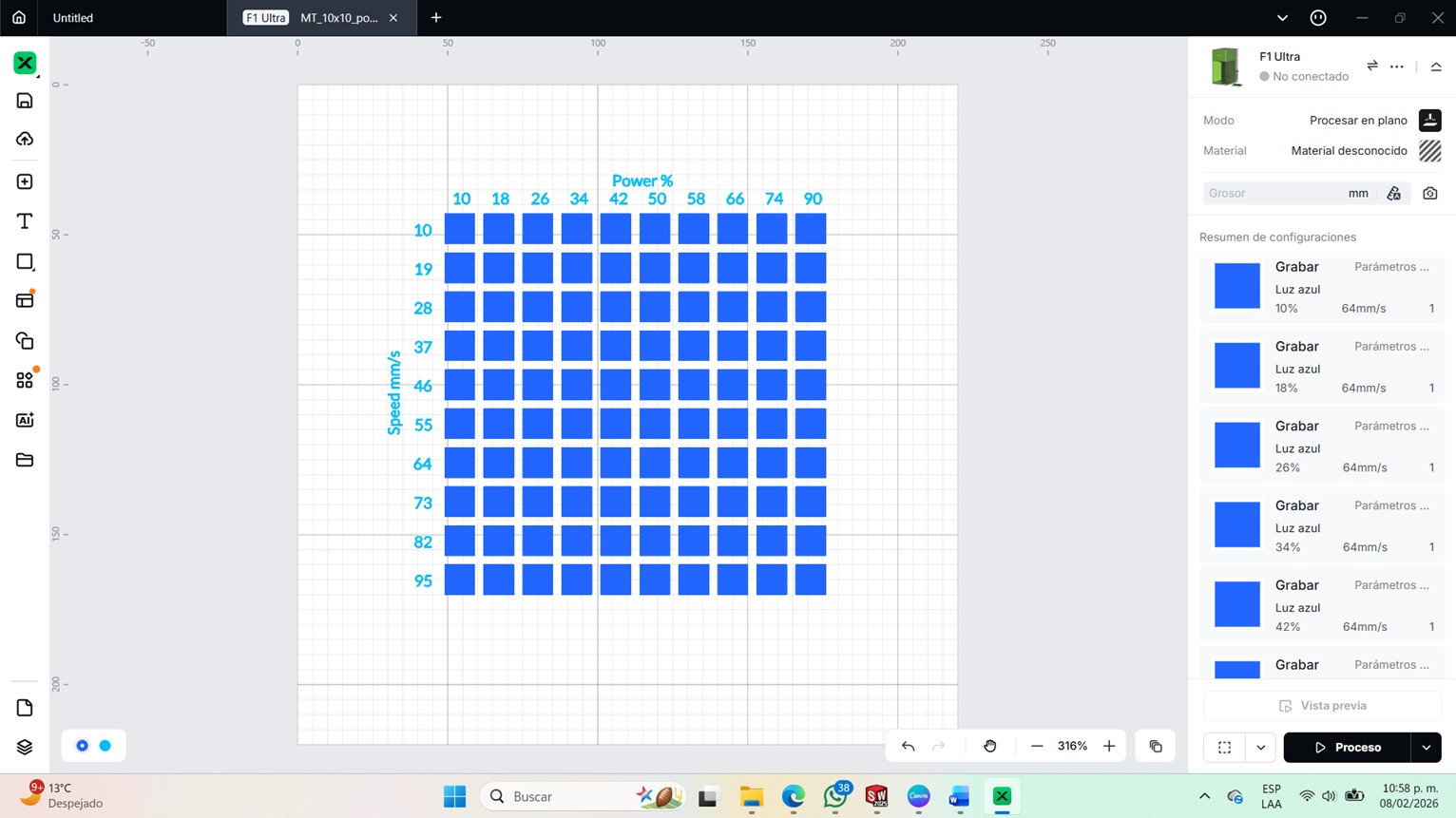
Then, it was moved to Inkscape download link in order to save the document as a DXF.
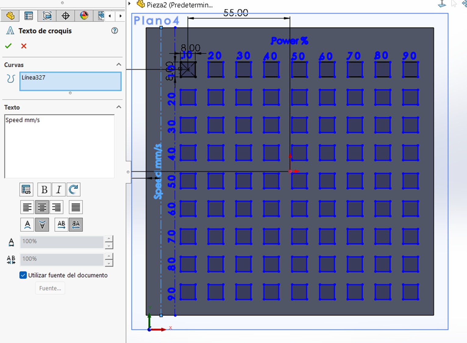
Manual method for creating the pattern
Using SolidWorks, a sketch was created on top of the extruded base, where a pattern of rectangles was made and text was added. For the side text, these parameters from the left panel were used.
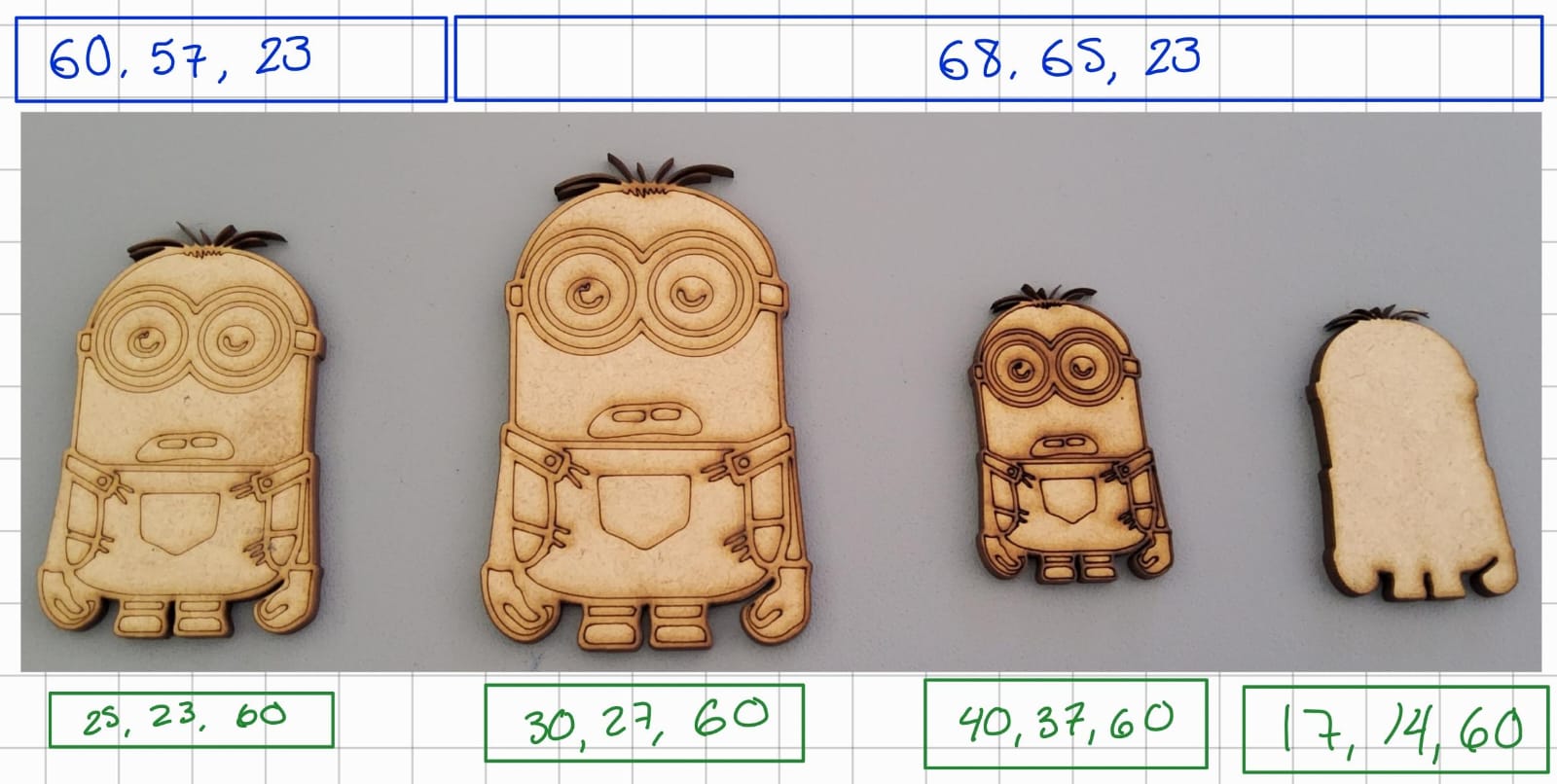
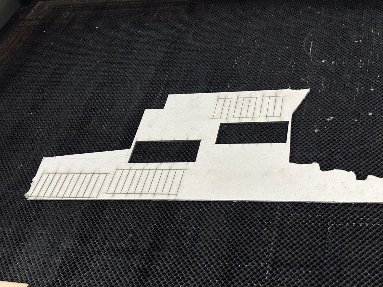
Another good comparative example is the following image, in which the parameters above (blue color) were used to cut completely through the surface, and those below (green color) are for engraving. The material used was 5mm MDF.
The settings within the program (SmartCarve) were:
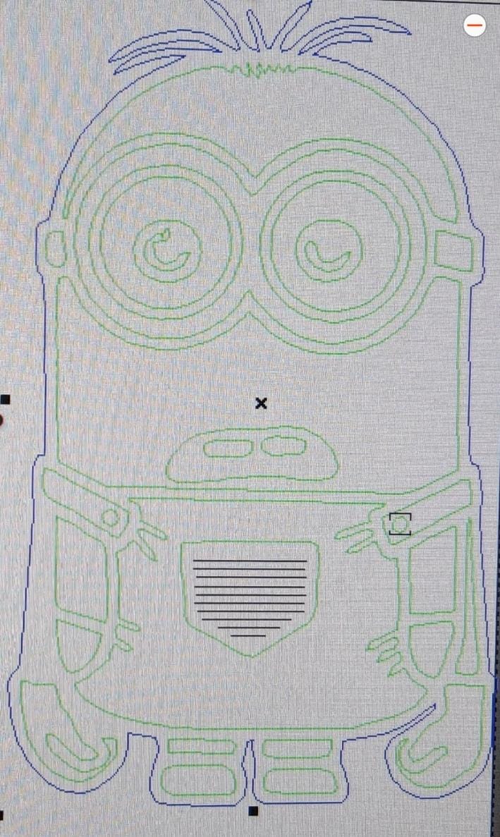
The parameters represent:
- First: Maximum Power
- SecondMinimum Power
- ThirdSpeed
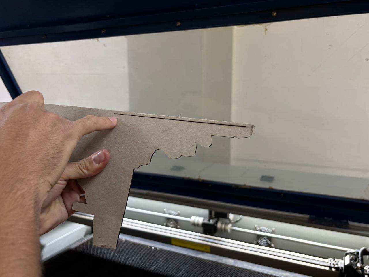
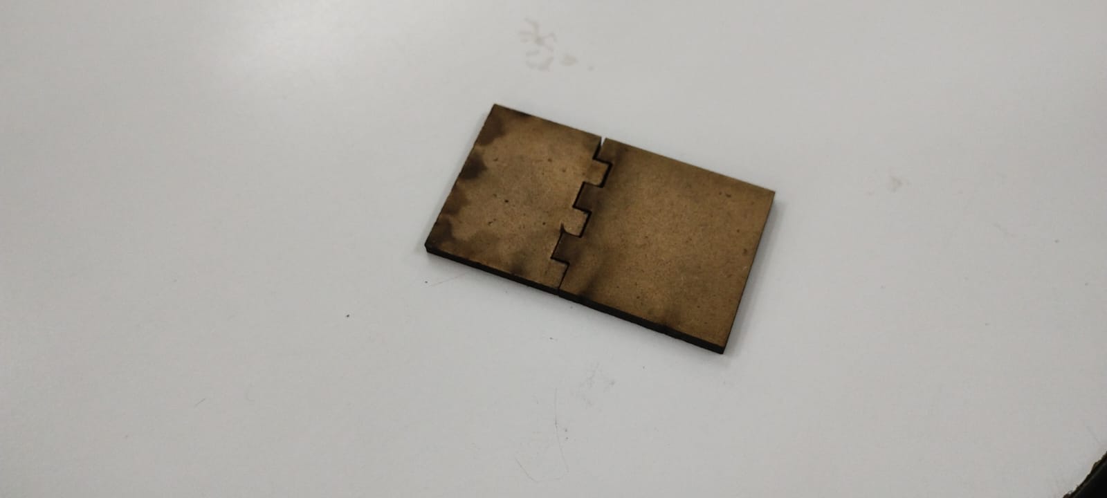
Kerf
The kerf is the width of material removed during laser cutting. It corresponds to the thickness of the beam plus the heat-affected zone, resulting in pieces that are slightly smaller than the original design.
To figure out the kerf of our machine we make 10 rectangles together for the machine to cut it off in 2.5 mm wide MDF, in that way by trying by putting the rectangles back together and measuring with a caliper the distance between the joined rectangles and the cutting edge, we were able to determine the kerf, by dividing the gap by the number of cuts.
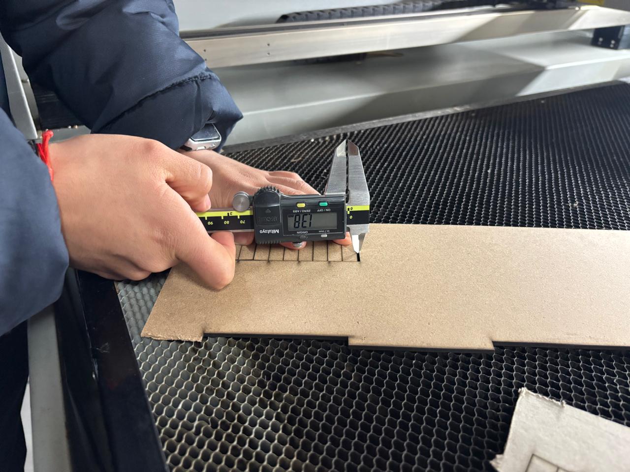
MDF 2.5mm 10 cuts Speed 40 mm/s Power 60%
2.5 mm/10 = 0.25 mm kerf
Tests Performed
Regarding the kerf tests, the corresponding files can be accessed to visualize the models that were created. Here you can download the files made.
- Kerf test: This test measures the amount of material removed by the router or the laser, which represents the cutting tolerance. To perform this test, a rectangle with 10 equally spaced lines is created, cut, and the resulting distances are measured (the smallest distance corresponds to twice the kerf, while the largest corresponds to the kerf).
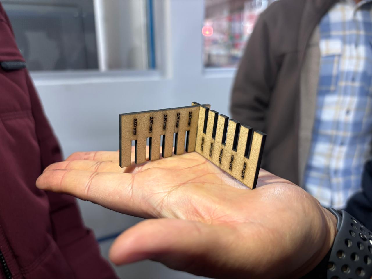
Joint clearance and types
In the case of joint types, the following models were developed. Here you can access to the files made. These will be explained in greater detail in the sections below.
Types of Joints
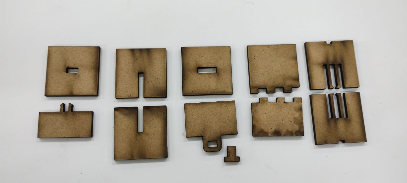
Snap Fit Joints:These use the elasticity of the material to lock parts together. A flexible "hook" or tab deflects during assembly and snaps into a hole or undercut, creating a secure connection without glue.
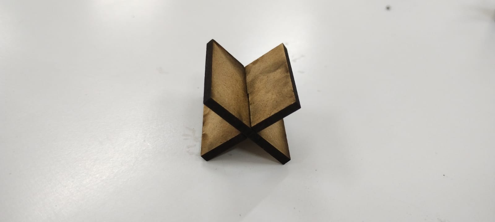
Finger Joints (Box Joints): One of the most common laser-cutting joints, consisting of interlocking "fingers" on the edges of two plates. They provide a large surface area for glue and are excellent for creating sturdy 90-degree corners in boxes.
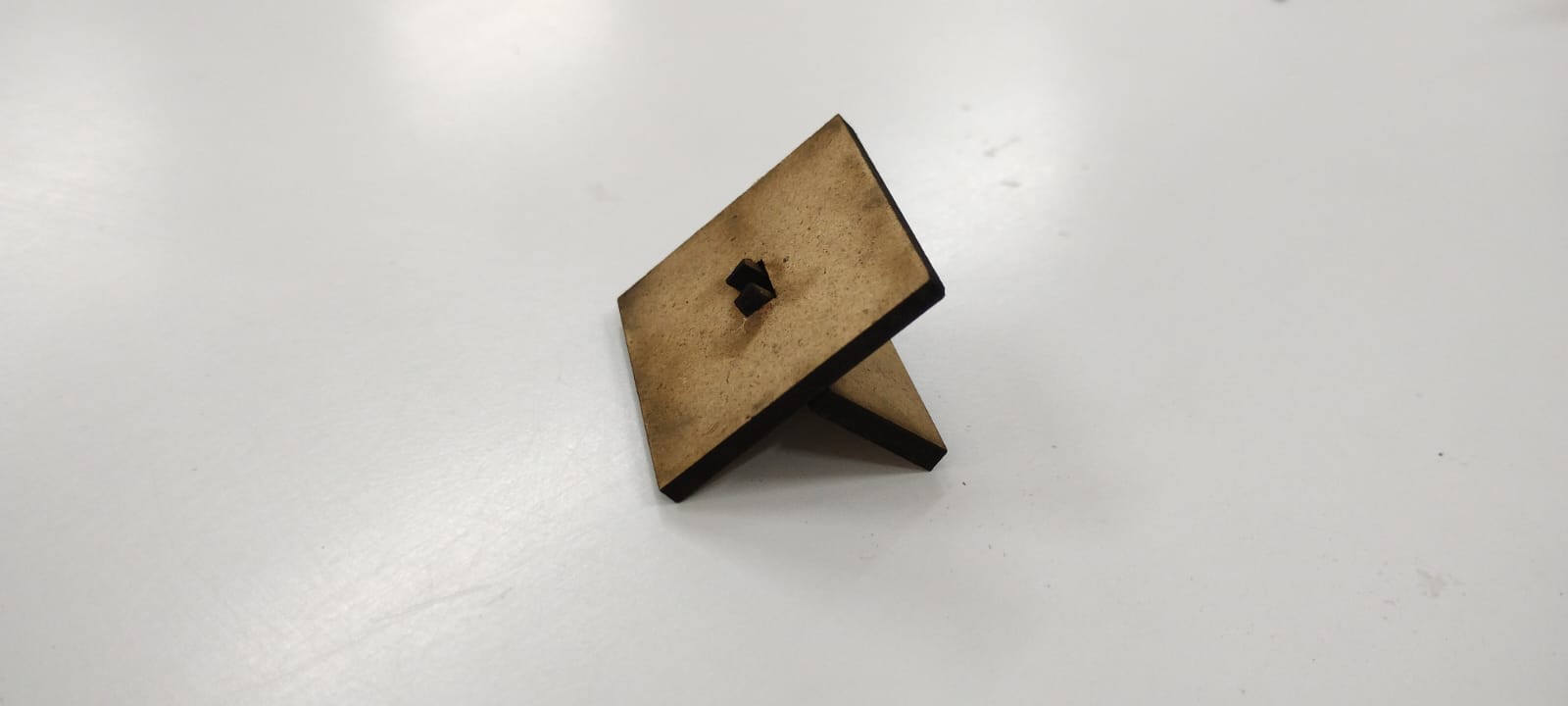
Wedge Joints:These involve a tab that passes through a slot, which is then secured by a small wedge or "key" driven into a hole in the tab. This creates a very strong mechanical lock that can be disassembled easily.
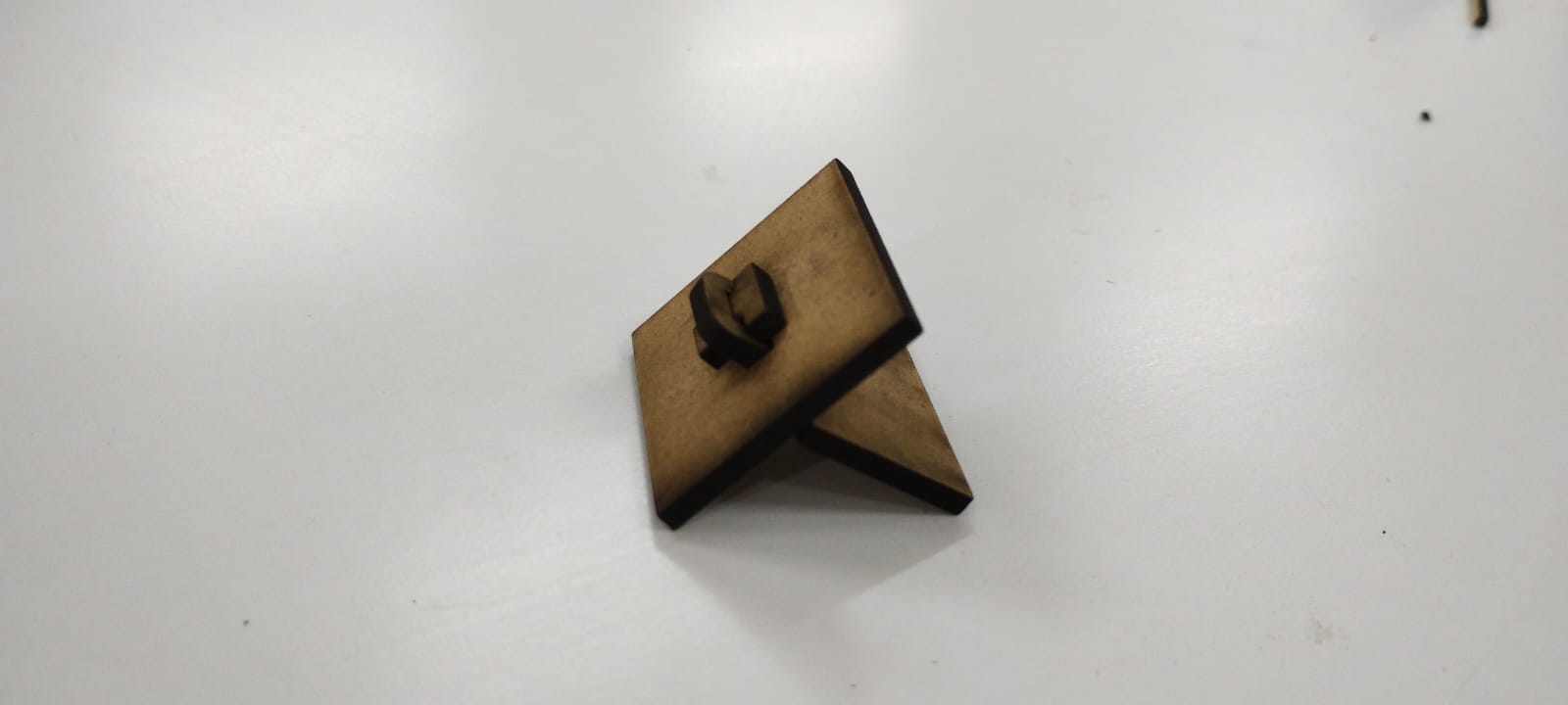
Pinned Joint:Similar to a hinge, these use a dowel, bolt, or a small laser-cut pin as an axis. This allows for rotation between two parts, making it ideal for moving mechanisms or linkage systems.
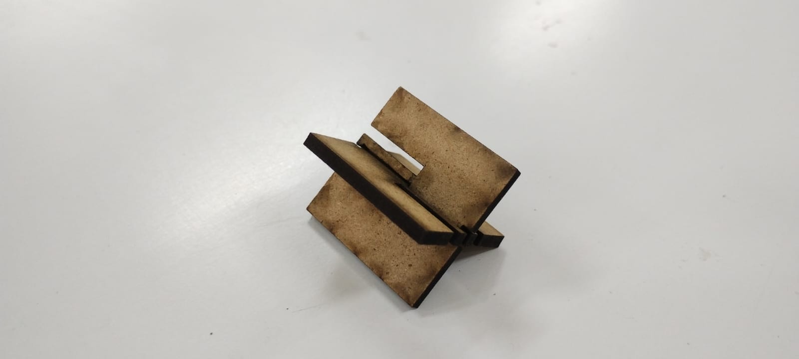
Press Fit Joint:These rely on high-precision friction (interference fit). The tab is designed to be slightly larger than the slot (accounting for the laser's kerf), forcing the fibers of the material to compress and hold the parts together tightly.
Flexure Joint:These use a specific pattern of laser cuts (like the ones in your Living Hinge project) to make rigid material like MDF or acrylic bendable. They act as a physical hinge without needing separate moving parts.
Programs
- Smart Curve
- Lightburn
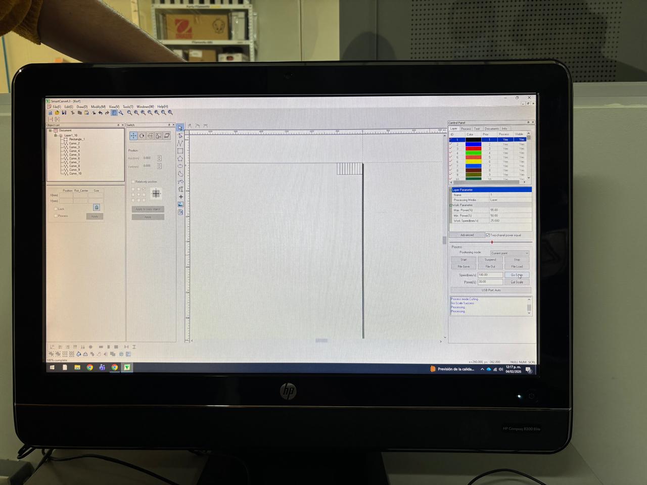
Setting parameters in the program
The program used by the laser cutters is called: SmartCarve 4.3. The program interface is shown in the image below:
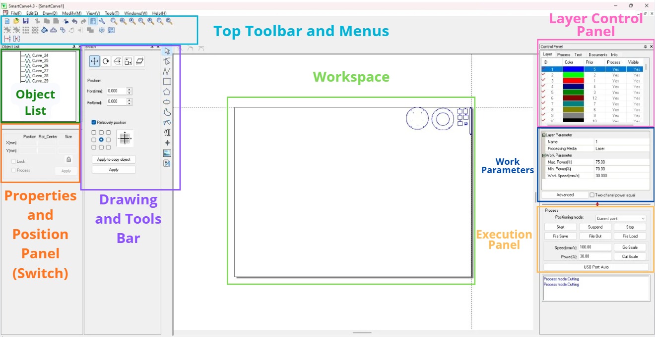
Function of each section
- Top Toolbar and Menus:It contains quick access menus (File, Edit, Draw, View) and icons for standard functions such as opening files, saving, copy/paste, and zoom tools for design visualization.
- Drawing and Tool Bar (Left Side):you select what to do in the workspace: Selection (the arrow used to move objects, geometric drawing (tools to create lines, rectangles, circles, and polygons directly in the program) and node Editing (to modify specific points of a vector).
- Object List:shows all elements present in the design (as seen in the image: Curve_24, Curve_25, etc.). It is useful for selecting specific overlapping pieces or organizing the order of curves.
- Properties and Position Panel (Switch):this panel allows you to: Modify coordinates (adjust the exact horizontal and vertical position in millimeters) and transformations (apply array copies (repetitions) or adjust the size of the selected object).
- Workspace (Canvas):The central white space where vectors are displayed.
- Layer Control Panel:This is vital for organizing work by color: ID and Color (defines which parts of the design will have certain parameters), priority (determines the cutting order, for example, cutting internal holes first and the outer contour last) and process/Visible (allows you to hide layers or decide if they should be sent to the laser).
- Work Parameters: This section allows you to change this parameters:
- Max. Power (%): Set to 75.00. This is the maximum strength on straight paths.
- Min. Power (%):Set to 70.00. This is the strength in curves and corners.
- Work Speed (mm/s):Set to 30.000. The travel speed of the laser head.
- Process Execution Panel:this is the command center for the machine: Start / Stop / Suspend the job, Go Scale / Cut Scale (used to have the laser trace the perimeter of the design to verify the material is correctly placed and last but not least, Speed / Power (Quick adjustments for manual head movement).
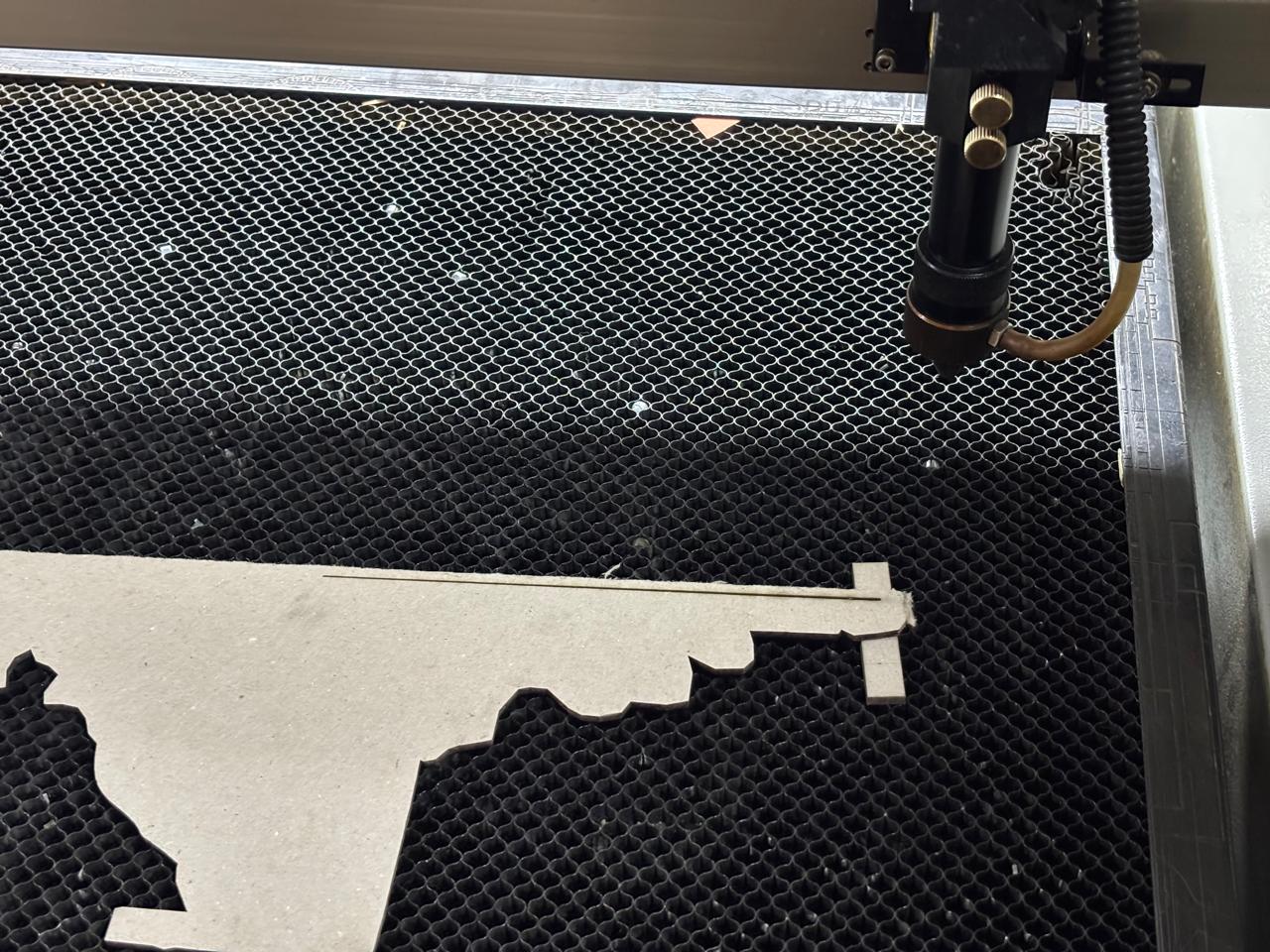
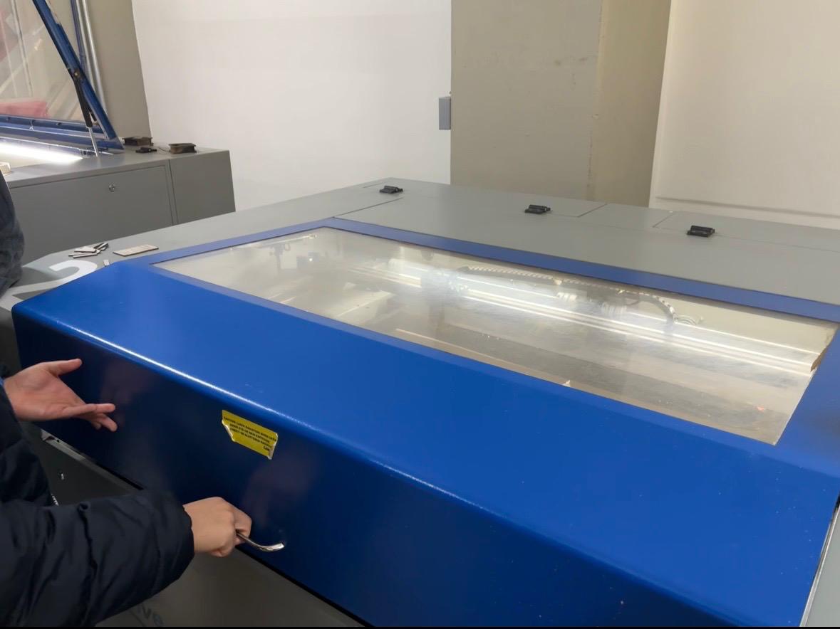
Operation of Laser Cutting Machines
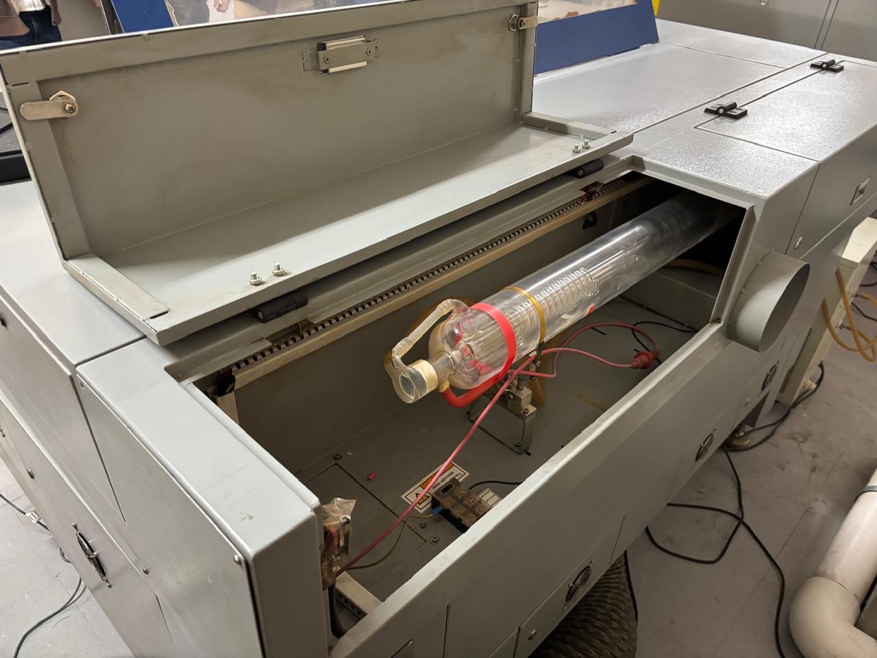
Laser cutting machines allow the creation of patterns by cutting materials using a high-energy light beam that burns the material. Laser machines are composed of different parts:
- Laser resonator: This is a sealed glass tube with two mirrors positioned facing each other. It contains CO₂ or other gases such as helium, hydrogen, among others. Through an electrical discharge, the gases are transformed into light, generating the laser beam.
- Cutting head: When the light beam reaches the cutting head, it passes through a lens that curves and focuses it into a single point.
- Cutting distance:A constant distance is maintained between the material and the laser nozzle.
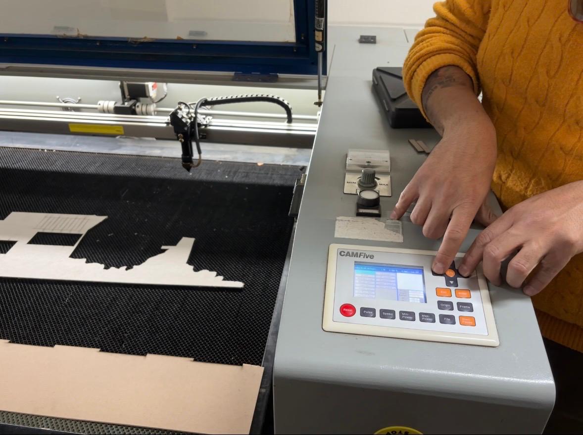
Steps to Use the Laser Cutting Machine
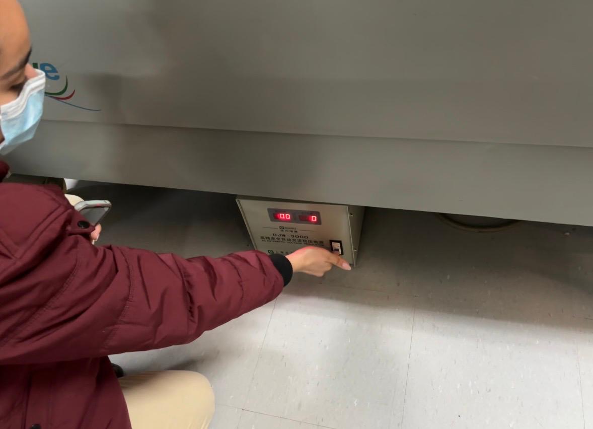
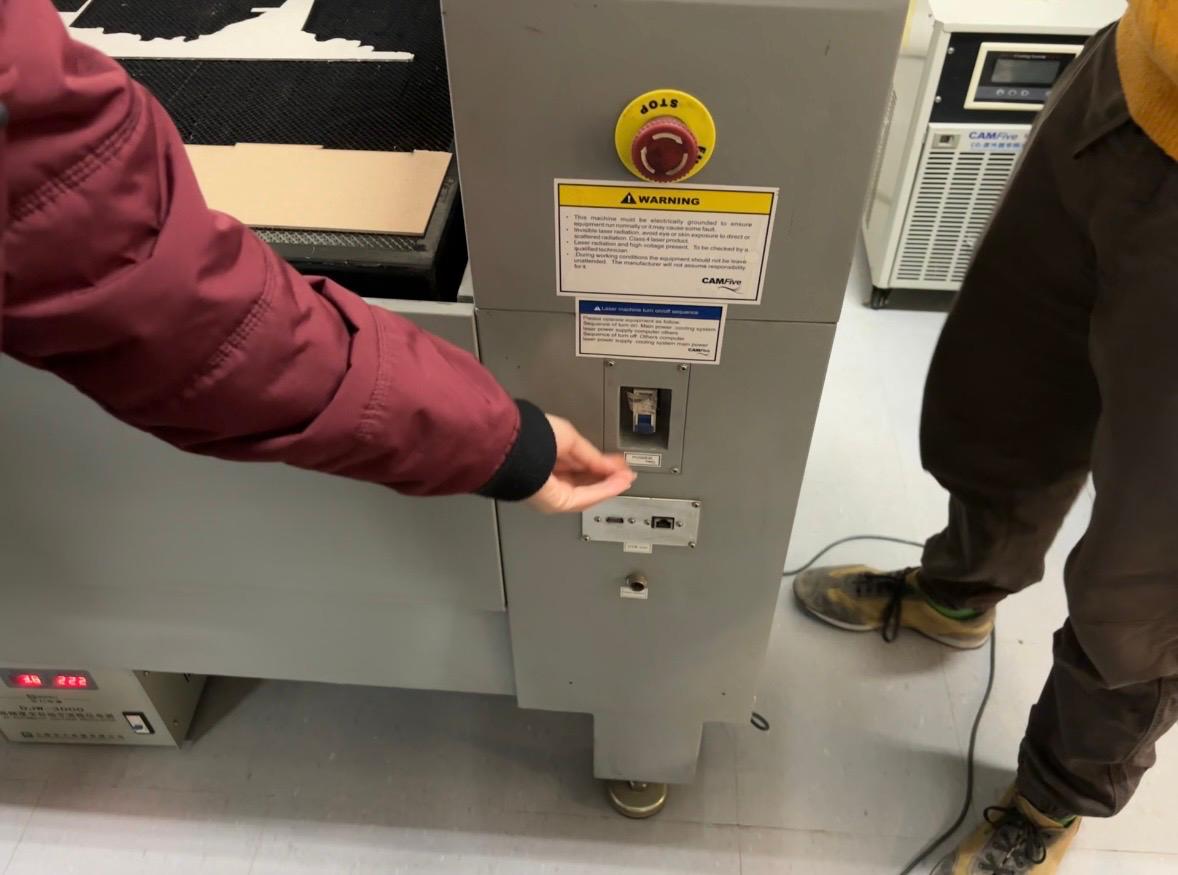
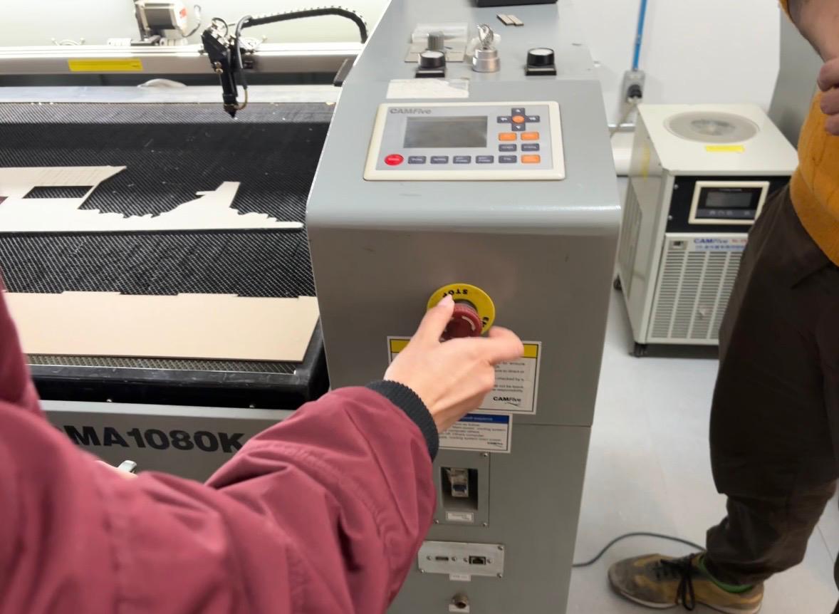
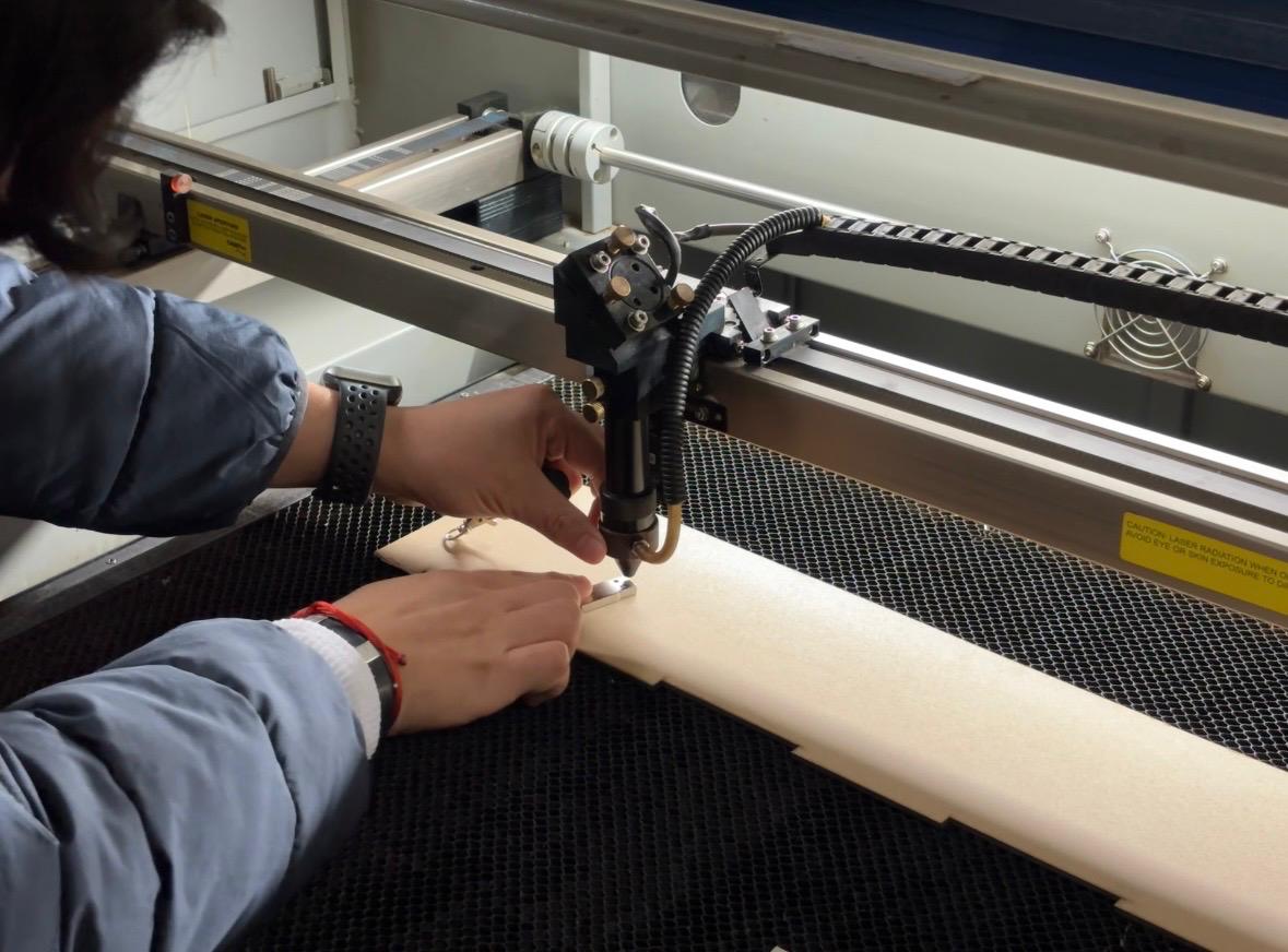
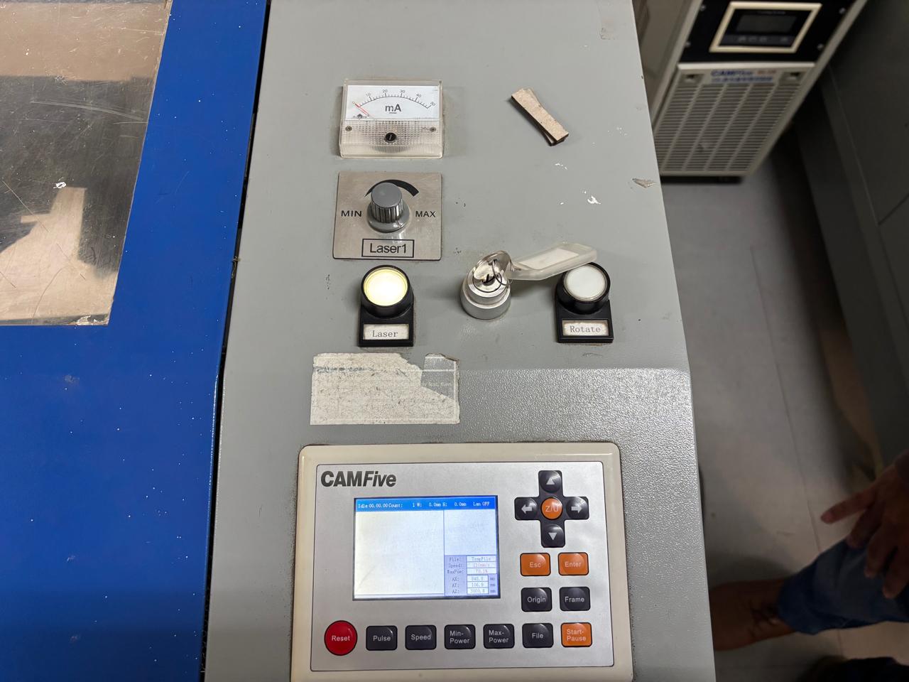
- First, the machine is connected to a power outlet. Then, the main switch located at the bottom of the machine is turned on, followed by the safety switch. The emergency stop is released, and the machine is activated using the key.
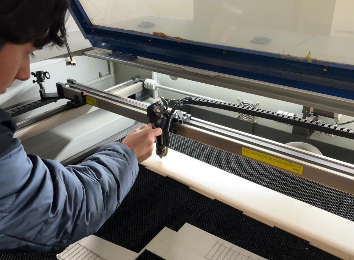
- Next, the laser beam is adjusted to maintain a distance of 5 mm from the material along the y axis. To do this, the nuts are loosened, a spacer with the indicated measurement is placed, and the nuts are tightened again.
- Once this step is completed, the laser power is adjusted.
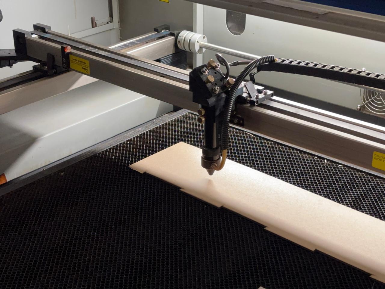
- The material to be cut is placed inside the laser machine. The origin point is then set directly on the machine by moving the laser using the directional arrows and pressing the origin button. To verify that the origin has been correctly set, the piece can be moved and the Esc button pressed to return the laser to the marked origin point. It is important to make sure your origin is in the upper right corner as the system’s default setting.
- On the computer, the USB drive containing the control program is inserted. Within this program, the files (which must be in DXF format) can be opened and adjusted according to the desired size or position.
- To identify the cutting area, the Go Scale option is selected. The computer will instruct the laser cutter to trace the area where the parts will be cut.
- The program includes a control panel divided into ID, color, priority, process, and visibility. Priority numbers indicate, from smaller to larger, the order in which the paths will be executed. Color allows the identification of paths within the design. These can be modified by selecting the desired elements, right-clicking on the color, and choosing Apply to picked object. This defines the layer order, placing engravings first and cuts last.
- Once all settings are completed, close the laser machine door, turn on the laser beam by pressing the corresponding machine button, and press Start in the program.
- After the process is finished, turn off the laser beam. Check that the parts were cut correctly, then remove the material and clean the machine to eliminate any remaining debris.
- To turn off the machine, reduce the laser power (ensuring the laser is off) and remove the safety key. Finally, return the emergency stop button to its original position, turn off the switch located at the bottom, and then turn off the main switch.
Note:Save the file using File → Save in .oud format to load it directly from the USB drive into the machine.
Conclusion
Learning how to use laser cutting tools is essential, as they are highly valuable for the prototyping of engineering projects. For proper training, it is not only necessary to understand their practical operation, but also their theoretical principles. This combined approach allows the integration of both aspects, strengthening essential knowledge in engineering, prototyping, and material modeling. Additionally, it is fundamental to operate this machinery with caution, as correct and responsible use is required to ensure safe and accurate results.