Group Assignment: Computer Controlled Machine
Before operating the CNC machine, it is mandatory to undergo a safety induction. Because the machinery operates with high-speed rotating tools that can project chips at high velocities, we established a set of mandatory rules to ensure a safe working environment.
Personal Protective Equipment
The following equipment must be worn at all times while inside the CNC area:
| Requirement | Safety Standard & Specification |
|---|---|
| Eye Protection | Impact-proof safety goggles; mandatory as chips can be projected during operations. |
| Hearing Protection | Noise protection headset; levels can reach up to 70dBA near the machine. |
| Body Protection | 100% cotton Lab coat/overalls. NO shorts or hanging garments allowed. |
| Footwear | Safety boots/shoes with toe protection from falling heavy objects. |
| Accessories | Zero jewelry policy. No hanging accessories or loose items that could cause entanglement. |
Operational Rules
When the machine is operational, these protocols are strictly enforced to prevent accidents:
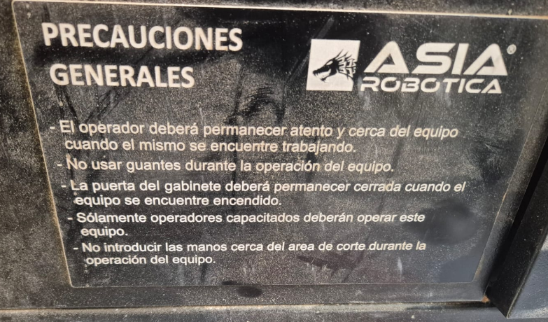
- Active Supervision: The operator must remain attentive and close to the machine when it is working.
- No Gloves: Do not wear gloves during the operation of the machine to avoid snagging risks.
- Enclosure Safety: The closet door must remain closed while the machine is on.
- Authorized Personnel: The machine must be operated exclusively by trained staff.
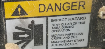
- Safe Distance: Do not put your hands near the cutting area while the machine is working.
Operational Rules
Operational Rules
Operational Rules
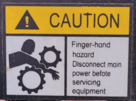
Operational Hazards & Waste Management
Dust and Static Safety
To prevent respiratory hazards, the integrated dust collector must be active during operation. Post-process, a secondary vacuum extractor is used to clear residual chips. Caution: The friction of fine particles moving through the hose generates significant electrostatic discharge (ESD). To avoid shocks, do not touch any grounded surfaces or the machine frame while vacuuming.
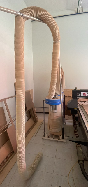
Dust Extraction
Control Panel Caution
The control interface houses a specific green circular button located next to the main switch. This button reconfigures the X-axis for the rotary add-on. Do not engage this button during standard 3-axis milling, as it will disable the primary axis and lead to job failure or mechanical errors.
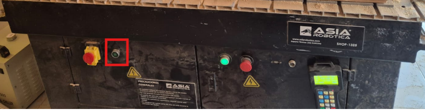
Button for reconfigures the X-axis
Pre-Operation Checklist
| Category | Verification Point |
|---|---|
| Environment | Floor must be clear of chips and debris to prevent slips. Maintain a safe perimeter; the gantry moves at high speeds. |
| Electrical | Be aware of high-voltage components. Treat the machine as "live" unless the E-Stop is engaged, as automated movements can trigger suddenly. |
| Tooling | Ensure the cutting tool is centered, sharp, and secured tightly within the collet. |
| Workpiece | Verify the material is flat and securely fixed. Inspect the toolpath for obstacles like clamps, screws, or dense knots in the wood. |
Machine Anatomy & Technical Specifications
The CNC Router used in our lab is a heavy-duty industrial machine designed for high-precision manufacturing and continuous production.
Main Components
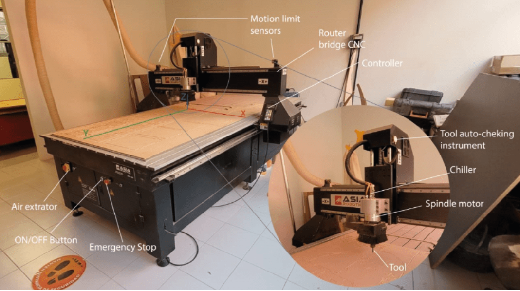
Diagram of the CNC machine components.
Technical Data Sheet
| Feature | Specification |
|---|---|
| Spindle Motor | 6 HP High-power water-cooled spindle (up to 24,000 RPM). |
| Workholding System | Vacuum hold-down system with a 10 HP turbine pump (Optional). |
| Suction Zones | 4 independent vacuum areas for versatile material sizing. |
| Duty Cycle | Designed for industrial 24/7 operation. |
| Construction | High-rigidity assembly to eliminate vibration and surface imperfections. |
| Design | Space-saving structure with an integrated control cabinet. |
The another CNC router used for this assignment is a machine custom-built by the university.
Component Identification
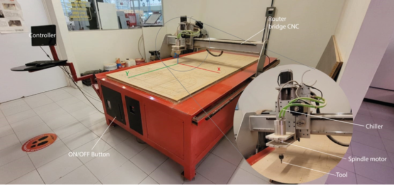
Identification of components
Technical Attributes
| Attribute | Details |
|---|---|
| Machine Type | Generic / Custom-made by University |
| Footprint / Dimensions | 3 x 1.8 x 1.7 meters |
| Motor Power | 4 HP @ 24,000 RPM |
| Power Supply | 220v / 2-Phase / 3.5 KW |
| Material Fixtures | Nails (Sacrificial board fixing) |
| Cooling System | External Chiller (Water-cooled spindle) |
Supported Materials
The CNC router is capable of processing a wide range of materials, from soft polymers to non-ferrous metals. Selecting the material is crucial for determining the appropriate feeds, speeds, and tooling.
| Material Category | Specific Materials | Description & Use Cases |
|---|---|---|
| Woods & Boards | Solid Wood (Soft/Hard), MDF, OSB, Plywood (Triplay) | Standard materials for furniture and structural prototypes. Includes veneered and laminated variants. |
| Polymers & Plastics | ABS, Acrylic, Styrene, Nylon, Polycarbonate, Polyethylene, PVC | Versatile engineering plastics ranging from high-transparency acrylics to impact-resistant polycarbonates. |
| Non-Ferrous Metals | Aluminum, Copper, Brass, Alucobond / Dibond ® | Soft metals and composites used for mechanical parts, signage, and decorative elements. |
| Specialized & Composites | Machinable Wax, Phenolic Resin (Bakelite), Solid Surface, Resins | High-density materials for mold making, high-heat applications, and premium countertops (e.g., Corian). |
Detailed Material Breakdown
| Material | Technical Description |
|---|---|
| ABS / Styrene | Impact-resistant thermoplastics for durable prototypes. |
| Acrylic | High-clarity polymer; requires precise speeds to prevent melting. |
| Alucobond / Dibond ® | Aluminum composite panel ideal for lightweight structural signage. |
| Aluminum / Copper / Brass | Soft metals that require specific chip loads and potentially lubrication. |
| Machinable Wax | Self-lubricating material for high-detail mold prototyping. |
| MDF (Standard/Laminated) | Engineered wood with uniform density; excellent for general milling. |
| Melamine | MDF or Particle board with a decorative coating; prone to chipping without down-cut bits. |
| Nylon (Nylamid) | Tough, low-friction engineering plastic for mechanical components. |
| Phenolic Resin (Bakelite) | Extremely hard, heat-resistant composite for electrical and industrial use. |
| Solid Surface | Mineral-filled acrylic/polyester resin used for high-end furniture. |
Machine Characterization: Feeds and Speeds
To establish the base parameters for our milling operations, we consulted the Shopbot Feeds and Speeds chart. This data serves as a reference for calculating the Chip Load, ensuring efficient material removal without overheating the tool or damaging the spindle.
Reference: Tooling Parameters Table
| Tool Name | SB# | Onsrud Series | Pass Depth | Chip Load | Flutes | Feed Rate (IPS) | Feed Rate (IPM) | RPM |
|---|---|---|---|---|---|---|---|---|
| V-Carbide Bit 1" (60°) | 13648 | 37-82 | 1 x D | .004 - .006 | 2 | 2.4 - 3.6 | 90 - 126 | 18,000 |
| V-Carbide End Mill 1/4" | 13642 | 48-005 | 1 x D | .005 - .007 | 1 | 1.5 - 2.1 | 90 - 126 | 18,000 |
| V-Carbide End Mill 1/2" | 13564 | 48-072 | 1 x D | .005 - .007 | 2 | 3.0 - 4.2 | 180 - 252 | 18,000 |
| Upcut Carbide End Mill 1/4" | 13528 | 52-910 | 1 x D | .005 - .008 | 2 | 3.6 - 4.8 | 180 - 252 | 18,000 |
| Downcut Carbide End Mill 1/4" | 13507 | 57-910 | 1 x D | .005 - .008 | 2 | 3.6 - 4.8 | 180 - 252 | 18,000 |
| Upcut Carbide End Mill 1/4" (O-Flute) | 1108 | 65-025 | 1 x D | .004 - .006 | 1 | 1.2 - 1.8 | - | 18,000 |
| Tapered Ball Nose 1/8" (Upcut) | 13636 | 77-102 | 1 x D | .003 - .005 | 2 | 1.8 - 3.0 | - | 18,000 |
| Surfacing Bit 1-1/4" | 13555 | 91-000 | 1/2 - 3/4 x D | - | 2 | - | 200 - 600 | 12,000 - 16,000 |
Mechanical Fixture Systems
Method 1: T-Slot Clamps
The machine bed features aluminum T-slot canals. These tracks allow us to slide adjustable metal clamps that exert downward pressure on the material. This system is highly reliable for heavy-duty milling where lateral forces are high.
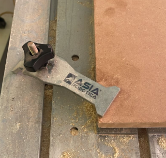
Securing the MDF board using the T-slot track and manual tightening clamps.
Method 2: Threaded Hole Grid
For increased versatility, the lab uses a fixture plate with a grid of threaded holes. This "spoilerboard" approach allows for custom clamping configurations and the use of sacrificial layers, ensuring the machine's aluminum bed remains undamaged during through-cuts.
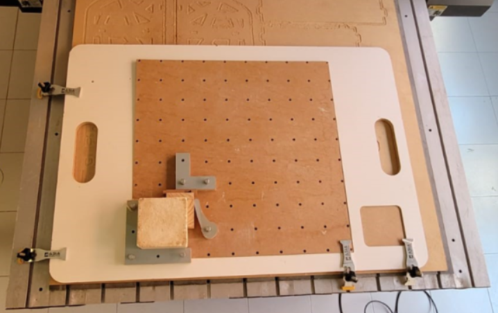
The grid system provides multiple anchor points for complex or irregularly shaped workpieces.
Clearance and Joints
A fundamental constraint in CNC milling is that the cutting tool is cylindrical. As the end mill rotates and moves along a path, it naturally leaves a radius equal to its own radius at any internal 90-degree corner.
The Problem: Internal Corner Radii
When designing press-fit joints, an unmodified square internal corner will prevent a sharp-edged mating piece from seating fully. This results in poor structural integrity and gaps in the assembly. To solve this without manual filing, we must modify the design geometry to allow the tool to "over-cut" the corners.
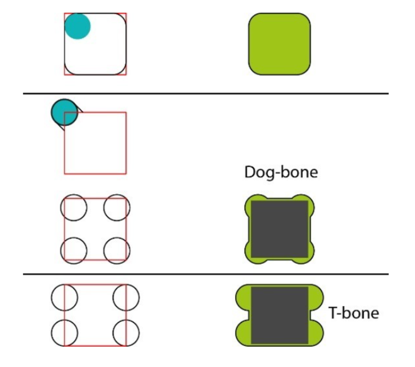
Dog-Bone & T-Bone visualization.
The Solutions: Dog-bones and T-bones
These design techniques involve adding small circular reliefs at the corners of a pocket or profile. This ensures that the square edge of the mating part can reach the very corner of the joint.
| Technique | Description | Best Use Case |
|---|---|---|
| Dog-bone Fillet | The tool path extends diagonally into the corner, creating a circular relief that resembles a bone shape. | Standard structural joints where the relief will be hidden by the thickness of the mating part. |
| T-bone Fillet | The relief is cut perpendicular to one of the joint's edges. This is often more aesthetically pleasing. | Visible joints where you want to minimize the visual impact of the relief cut on one side. |
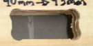
Test Piece Design
To guarantee precise assemblies, we designed a "tolerance comb" in SolidWorks. This piece allows us to measure the kerf (material removed by the bit) and find the exact tolerance required for press-fit joints to seat securely without damaging the material.
CAD: Modeling the Tolerance Comb
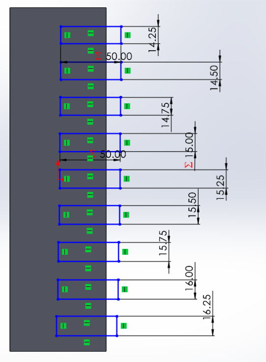
SolidWorks sketch of the test comb
CAM Preparation: VCarve Pro
Once the design was exported in DXF format, we used VCarve Pro o generate the toolpaths. At this stage, we defined the tool parameters based on our previously established Feeds & Speeds chart.
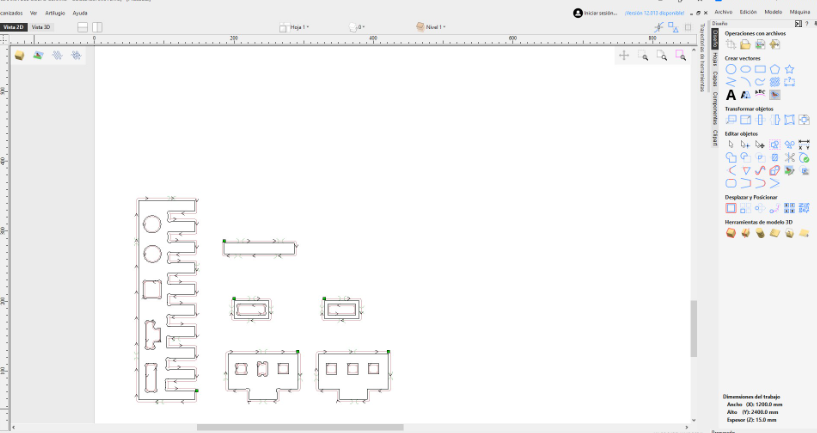
Configuring the cutting strategy and selecting the appropriate tooling.
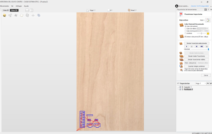
3D simulation of toolpaths .
Final Results & Physical Testing
Dog- Bone of the test piece
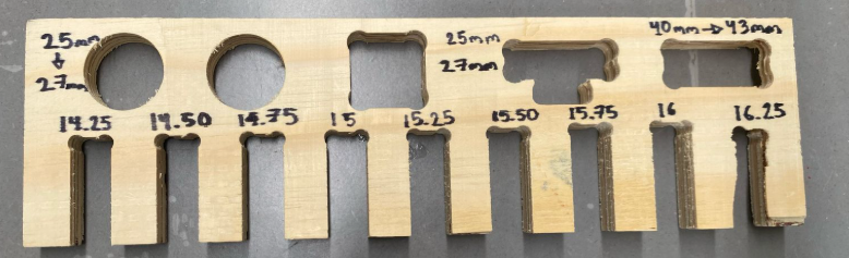
View of the comb
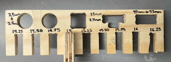
Test demonstrating the mechanical fit .