Final Project:
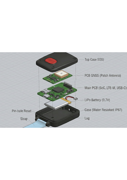
In many families, caring for an elderly relative with dementia is a constant, deeply emotional challenge. The reality is that 24/7 supervision is almost impossible, leading to a permanent state of worry. A loved one can leave the house unnoticed, become disoriented, and forget how to return in just a matter of seconds.
Every minute that passes without knowing where they are turns into anguish, fear, and uncertainty. This isn't just about safety—it's about the emotional toll on a family living with the constant dread of "what if." SafePath-RM was born from the need to bridge that gap between independence and security.
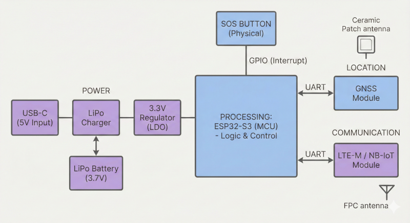
System Architecture & Block Diagram
The following diagram describes the interaction between the three main stages of my tracker: Power, Processing, and Output.
Power Stage
Located on the left, this stage manages the device’s power. The USB‑C provides 5V to the LiPo charger, which in turn maintains the 3.7V battery. The LDO regulator is crucial to stabilize the voltage at 3.3V, the level required by the microcontroller.
Processing Stage
At the center of the system is the ESP32‑S3 (MCU). This chip receives an interrupt signal from the SOS Button. When activated, the processor wakes from its low‑power mode to coordinate data capture and subsequent transmission.
Output Modules (Location and Communication)
On the right, the system splits into two output functions via UART communication:
- GNSS Module: “Listens” to satellites through the Ceramic Patch Antenna to obtain precise location.
- LTE‑M / NB‑IoT Module: “Speaks” to the cellular network via the FPC Antenna to transmit the obtained coordinates to the cloud.