• Probe an input device(s)'s analog levels and digital signals (As a minimum, you should demonstrate the use of a multimeter and an oscilloscope.)
The objective of this assignment was to explore and analyze different input devices by measuring their analog and digital signals. We used a multimeter and an oscilloscope to understand how each sensor behaves.
What is an Input Device?
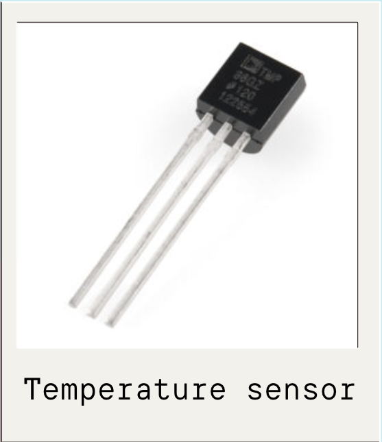
An input device is a component that detects changes in the environment such as: temperature, light, motion or pressure. It converts them into electrical signals that a microcontroller can read and process. Also, an input device allows a user to interact with and control it.
Analog Signal:
An analog signal is a continuous signal that can change in strength and frequency. Besides, analog signals can take any value within a range (0V to 3.3V). Some examples are: sound waves, voltage fluctuations and radio waves; the value changes gradually.
Digital Signal:
A digital signal is a discontinuous signal that represents data as a sequence of discrete values, typically binary digits (0s and 1s). Unlike analog signals, digital signals switch between two fixed voltage levels or states: LOW (0V), HIGH (3.3 or 5V). Basically, it works like a switch: On or OFF.
I2C Communication:
I2C (Inter-Integrated Circuit) is a digital communication protocol that allows multiple devices (sensors, displays, etc.) to communicate with a microcontroller using only two wires. Unlike simple digital signals, I2C allows the transmission of structured data between devices. I2C has 2 wires:
What is an Osciloscope?
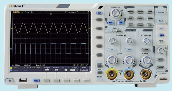
An oscilloscope is an instrument that graphically displays the variation of electrical signals over time. To measure our signals, we used an MDO322 Mixed Domain Oscilloscope. You can find how to use in the electronics design Group Assignment.
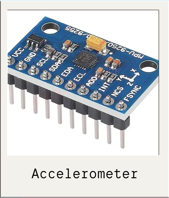
Accelerometer
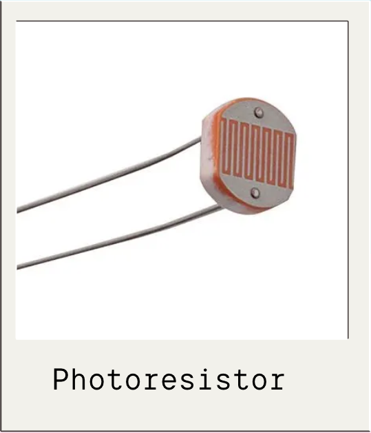
Photoresistor
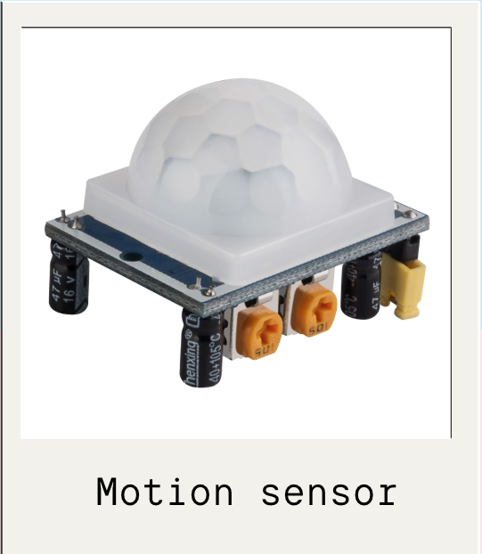
Motion sensor