9. Input Devices
Group Assignment
- Probe an input device’s analog levels and digital signals.
1. Introduction to VICTOR 152S
The VICTOR 152S is a “three-in-one” tool that eliminates the need to carry multiple instruments. It features a built-in oscilloscope, multimeter, and signal generator with easy switching. For more details, refer to the user manual.
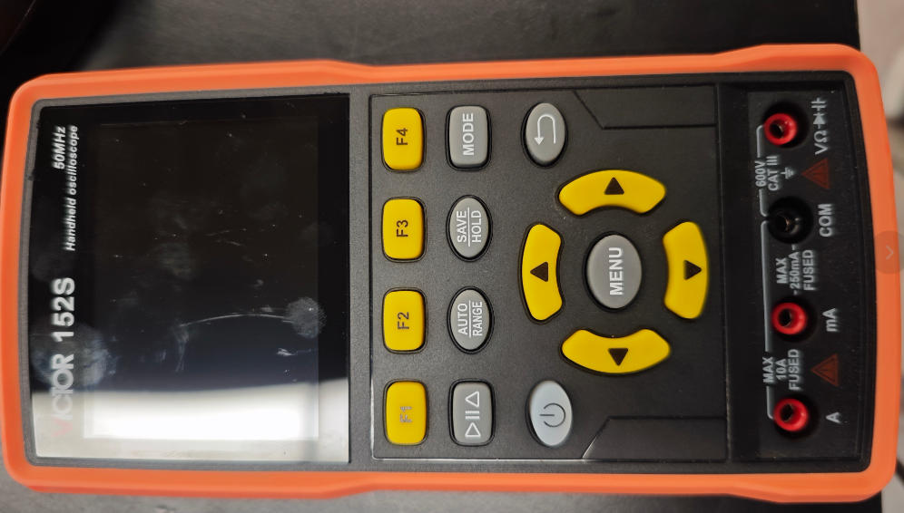
Key Features (Oscilloscope):
- Bandwidth: 50MHz (Dual Channel).
- Sampling Rate: 280MSa/s (Real-time), ensuring precise waveform detail capture.
- Measurement Functions: Supports automatic measurements (Frequency, Period, Peak-to-Peak, Max/Min, Duty Cycle, etc.).
2. Controlling an LED with a Push-Button
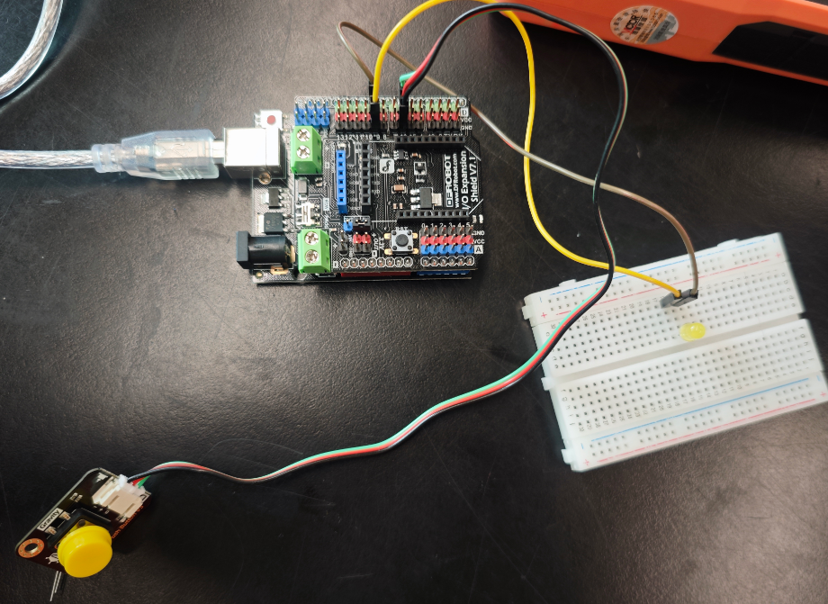
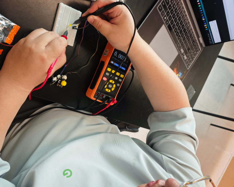
We used the VICTOR 152S in multimeter mode to detect the digital signals of a push-button sensor. The button controls the LED state, and we measured the voltage difference transmitted to the development board in both ON and OFF states.
2.1 Wiring
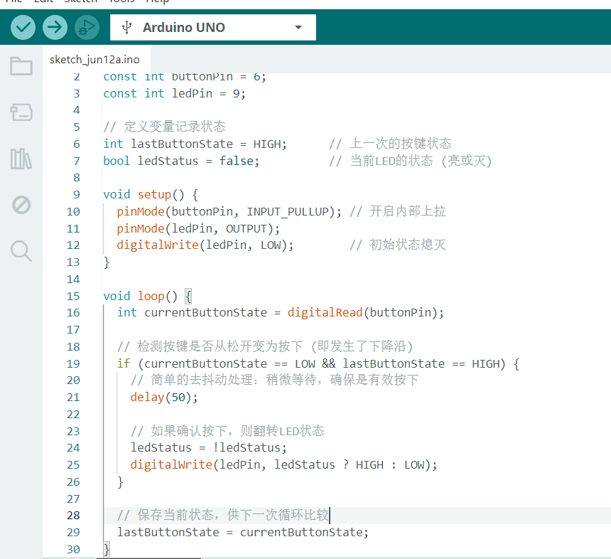
2.2 Code
2.3 Multimeter Setup (DC Voltage Mode)
- Black probe connected to GND.
- Red probe connected to the sensor’s DO (Digital Output) pin.
Voltage Changes:
- Button OFF (LED ON): The module outputs a high level at the DO pin ≈ 2.2813V.
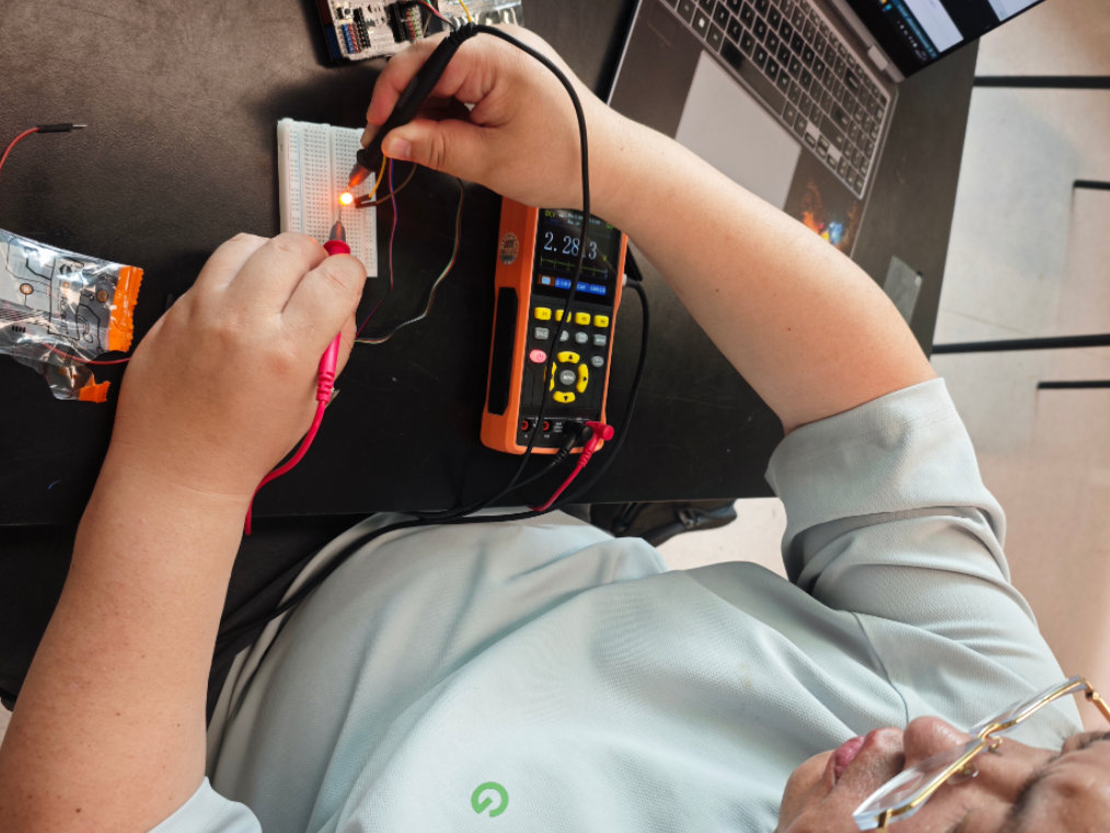
- Button ON (LED OFF): The module outputs a low level ≈ 0.0034V.
3. IR Sensor Control (LED Blinking)
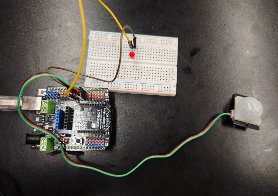
We used the VICTOR 152S handheld oscilloscope to observe the waveform of an LED blinking three times, controlled by an infrared (IR) sensor on an Arduino UNO.
3.1 Wiring
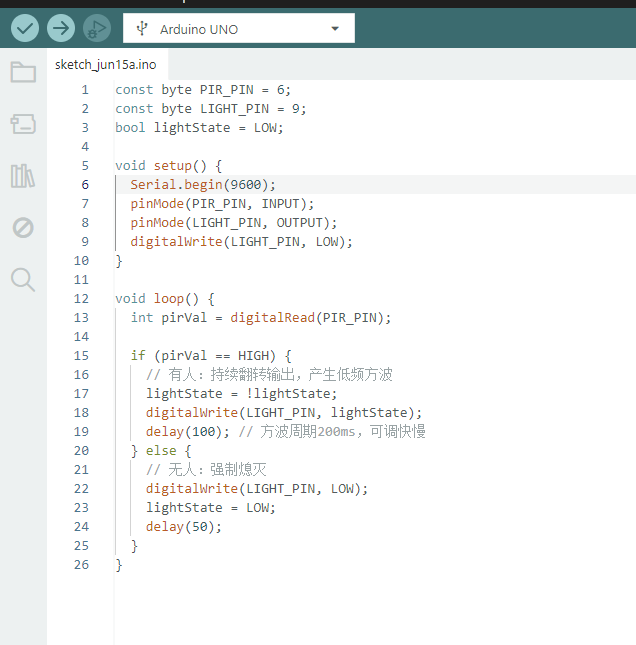
3.2 Code
3.3 Oscilloscope Settings
- Probe: CH1 connected to D9, GND clip connected to Arduino GND.
- Voltage/Div: 3V/div.
- Time/Div: 20ms/div to 100ms/div. Video
9.Input Devices
This week I worked on defining my final project idea and started to getting used to the documentation process.
Group Assignment
Probe an input device’s analog levels and digital signals.
Useful links
Code Example
Use the three backticks to separate code.
// the setup function runs once when you press reset or power the board
void setup() {
  // initialize digital pin LED_BUILTIN as an output.
  pinMode(LED_BUILTIN, OUTPUT);
}

// the loop function runs over and over again forever
void loop() {
  digitalWrite(LED_BUILTIN, HIGH);   // turn the LED on (HIGH is the voltage level)
  delay(1000);                       // wait for a second
  digitalWrite(LED_BUILTIN, LOW);    // turn the LED off by making the voltage LOW
  delay(1000);                       // wait for a second
}
Gallery

Video
From Vimeo
Sound Waves from George Gally (Radarboy) on Vimeo.