Week11 - Networking and Communications
Group Assignment
The link to our group work: https://fabacademy.org/2026/labs/chaihuo/docs/week11/msc/week11_group_assignment
For our group assignment at Chaihuo Makerspace, we went way beyond just sending a simple high/low signal between two boards. We built a multi-hop IoT network using our populated custom PCBs, integrating MQTT, Wi-Fi, and LoRa protocols. We set up an ESP32-C3 to act as a Wi-Fi/MQTT subscriber, which then forwarded the received text strings via UART to a Grove LoRa module. A remote RP2040 board then caught that LoRa signal and displayed the message on an I2C OLED screen.
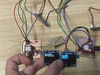
Participating in this integration taught me several critical lessons about how hardware actually communicates:
"Wireless" still relies on strict physical hardware: During our earlier BLE experiments, I saw firsthand that an ESP32-C3’s wireless capability is practically useless (dropping at 10cm) without a proper IPEX antenna attached. Furthermore, the wireless LoRa modules still depend on strict physical wiring on the PCB—if you accidentally swap the TX and RX UART lines between the MCU and the radio, the entire chain goes dead silently.
The power of a Broker (Decoupling): I learned that devices don't need to be hard-paired directly to each other. By using a Mosquitto MQTT broker on a PC, we decoupled the network. The remote RP2040 didn't even need internet access; it just passively listened to the LoRa radio, proving how you can mix offline and online nodes in one system.
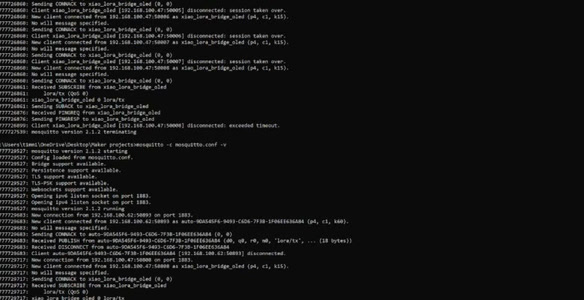
The Microcontroller as a Translator: Watching the ESP32-C3 grab a payload from the internet (MQTT/Wi-Fi) and instantly translate it into a local serial signal (UART) for the LoRa module was a huge "Aha!" moment. It perfectly demonstrated how a microcontroller acts as a bridge between totally different communication protocols.
Connection to my Final Project**:**
This group exercise was the exact stepping stone I needed. Seeing how comfortably the ESP32-C3 managed Wi-Fi connections and routed incoming data gave me a solid mental model for network programming. When it came time to build the communication prototype for my electro-acoustic Morin Khuur, I felt incredibly confident programming the ESP32 to broadcast live FFT audio data over Wi-Fi.
Because audio visualization needs to be extremely fast and responsive, I decided to try UDP as initial step. I programmed the ESP32 to continuously fire data packets over the local network to a Processing sketch on my laptop. Understanding how to cleanly format and structure these data payloads—a direct lesson from our MQTT group work—made getting the PC and the Morin Khuur to "talk" seamlessly much easier.
Individual Assignment
Wireless Audio-Visual System: ESP32C3 and Processing via UDP
The Architecture & Protocol Choice
For my Morin Khuur interactive final project, I needed to transmit real-time audio analysis data from the ESP32C3 microcontroller to a computer screen through Wifi.
Sender (Arduino):
-Mainboard: XIAO ESP32C3 & custom PCB
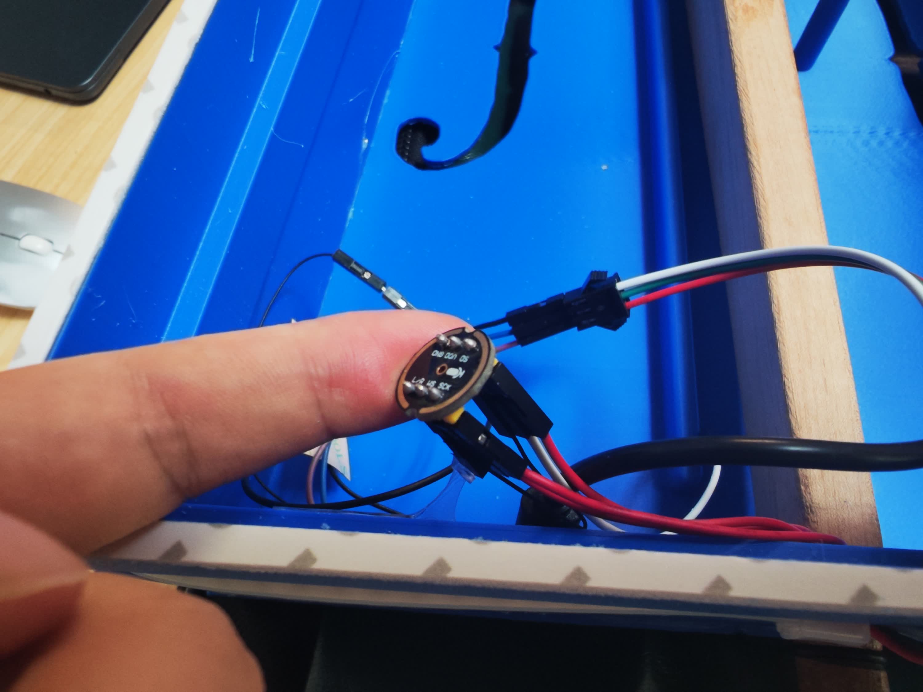
-Input: INMP441 I2S Omnidirectional Digital Microphone
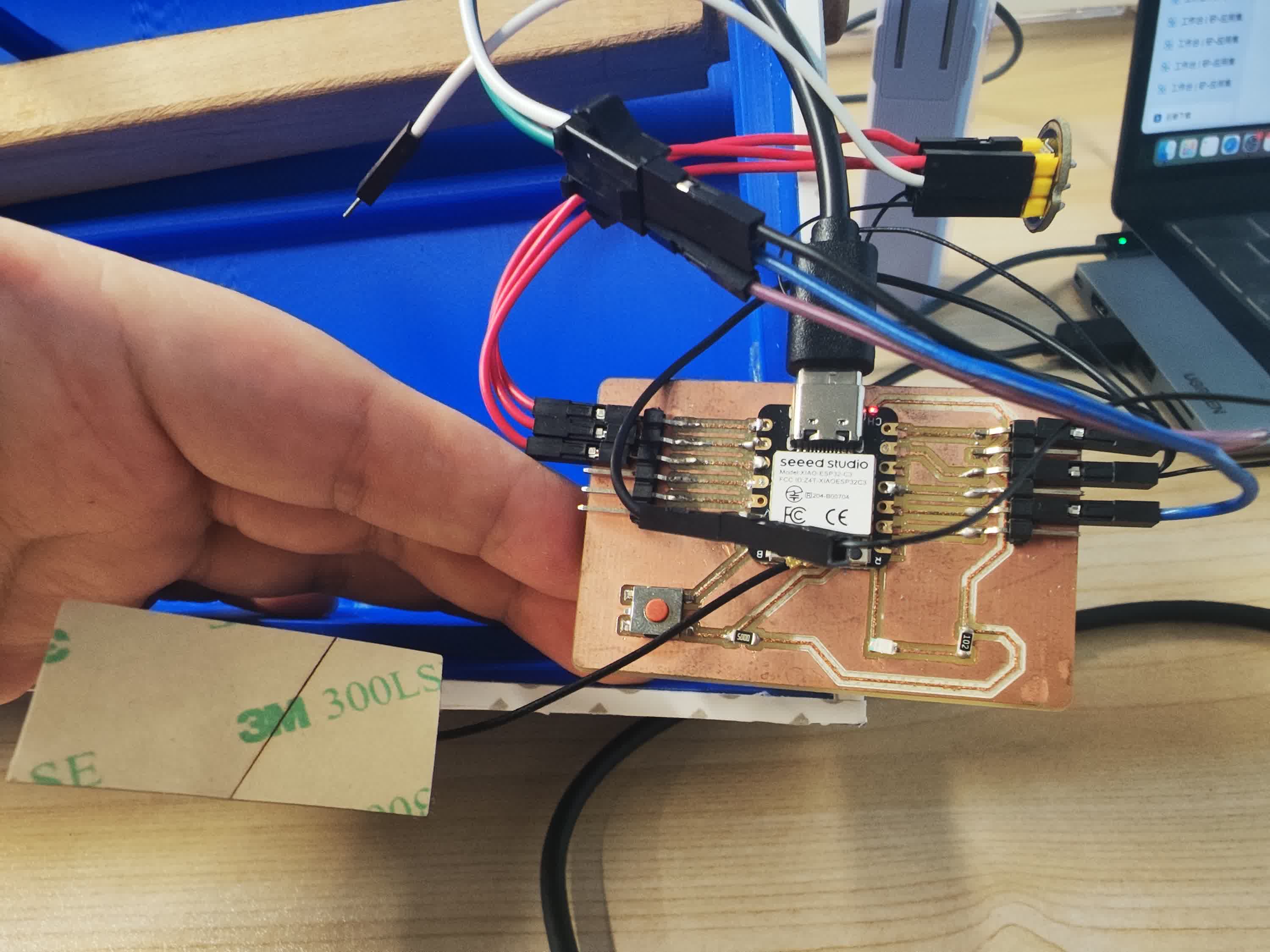
Receiver:** Processing on computer**, to show the music sound visualization
Because the ESP32C3 is a single-core chip heavily loaded with reading the I2S microphone, performing Fast Fourier Transform (FFT), and driving LEDs, I needed a highly efficient, lightweight communication protocol. I chose UDP (User Datagram Protocol) over TCP/WebSockets for the initial phase.
UDP is connectionless and prioritizing speed over guaranteed delivery, making it perfect for real-time visual rendering where dropping a single frame is acceptable. The network was established using a 2.4GHz personal mobile hotspot.
Wired Communication: The I2S Audio Protocol
Before the ESP32 can broadcast any frequency data over Wi-Fi, it first has to actually "hear" the Morin Khuur. For the internal hardware communication between the microphone and the microcontroller, I used the I2S (Inter-IC Sound) protocol.
Instead of dealing with messy analog voltage readings and the ESP32's internal ADC (which can be noisy), I chose a digital I2S microphone. It processes the analog sound waves internally and sends a pure, high-quality digital stream directly to the ESP32.
Setting up this chip-to-chip communication required wiring three specific data lines:
-
BCLK (Bit Clock): This acts as the heartbeat pulse, keeping the microphone and the ESP32 perfectly synchronized so no data bits are lost.
-
WS / LRCK (Word Select): A slower clock signal that toggles high and low to tell the ESP32 whether the incoming audio bits belong to the Left or Right audio channel.
-
SD / DIN (Serial Data): The actual pipeline where the raw binary audio waveform travels into the ESP32.
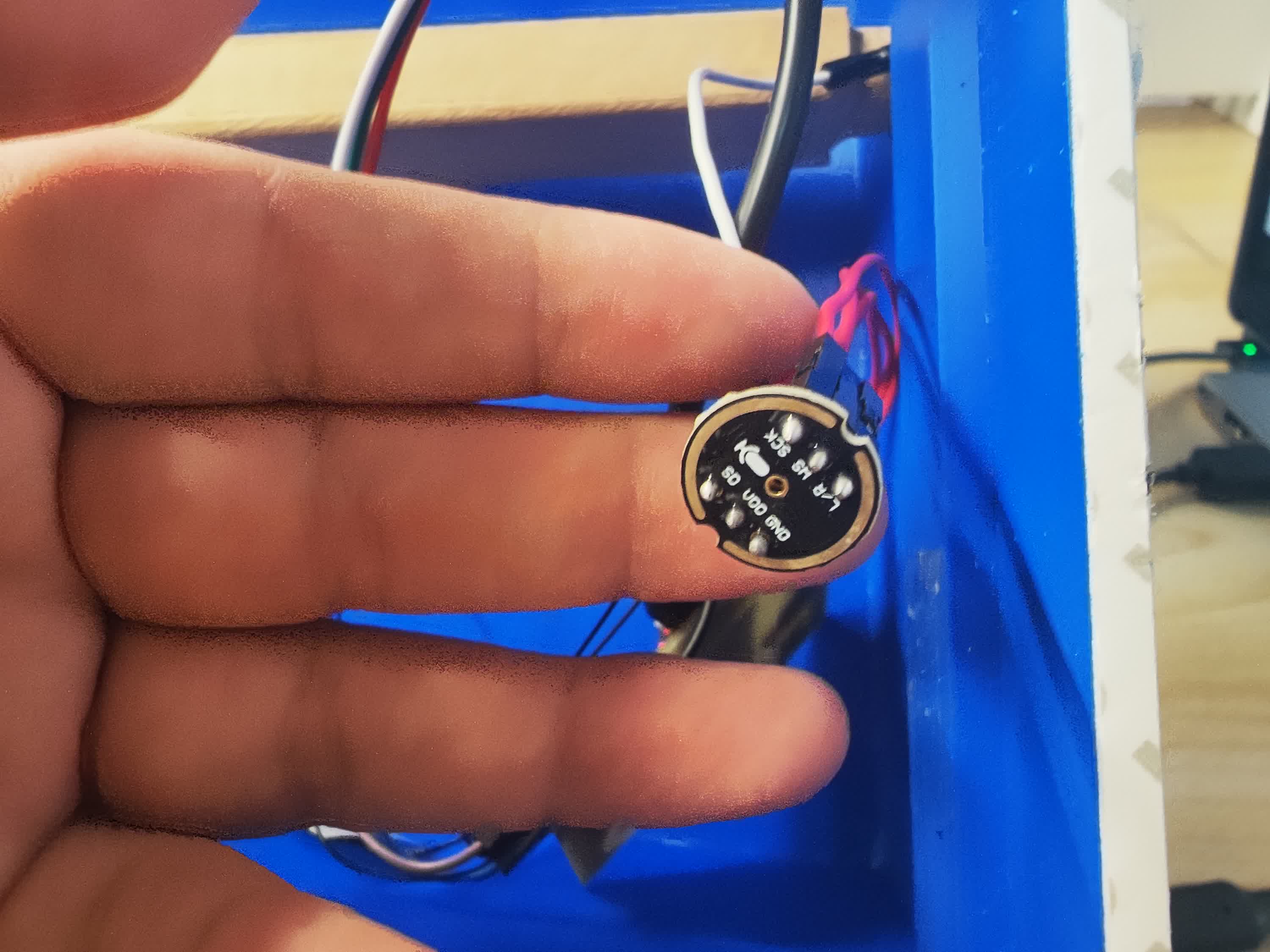
By successfully establishing this wired I2S link, the ESP32 receives a continuous, clean audio stream to feed into the FFT algorithm. Once the audio is mathematically sliced into Bass, Mid, and Treble data, it is then handed over to the wireless UDP protocol to be broadcast to my laptop.
**Network Prototyping (The "Hello World" of UDP) **
Before integrating the complex microphone and FFT code, I followed the golden rule of engineering: Test the communication link first using dummy data.
The Sender (Arduino):
Since the ESP32C3 only supports 2.4GHz Wi-Fi, I set up a 2.4GHz personal hotspot on my phone and connected my Mac to it. I wrote a simple Arduino sketch that generates random numbers for Bass, Mid, and Treble, packages them into a comma-separated string (e.g., "150,80,210"), and broadcasts them via UDP to my Mac's IP address on port 8888.
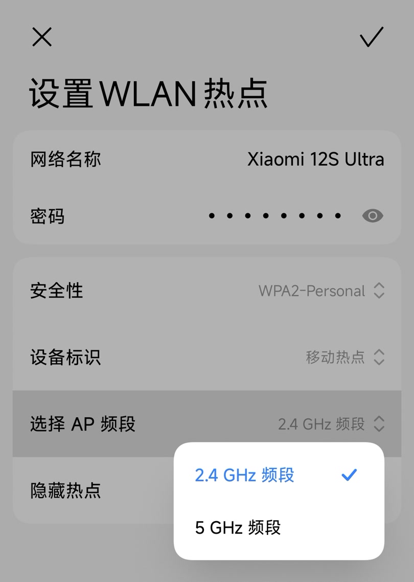
Check the IP address:
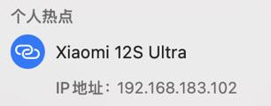
Wifi (2.4G) testing code on Arduino:
#include <WiFi.h>
#include <WiFiUdp.h>

// ========== ⚠️ 你只需要修改这 3 行 ==========
const char* ssid = "Xiaomi 12S Ultra";       // 改成你的手机热点名称 (保留双引号,不要有中文)
const char* password = "HOTSPOT_PASSWORD";   // 改成你的手机热点密码
const char* pc_ip = "192.168.183.102";         // 改成你刚刚抄在纸上的 Mac IP 地址!
// ===========================================

const int udp_port = 8888; // 约定的专属通道门牌号
WiFiUDP udp;

void setup() {
  Serial.begin(115200);

  // 开始连接 Wi-Fi
  Serial.print("Connecting to Wi-Fi...");
  WiFi.begin(ssid, password);

  // 如果没连上,就一直等,并且打印小点点
  while (WiFi.status() != WL_CONNECTED) {
    delay(500);
    Serial.print(".");
  }

  // 连上啦!
  Serial.println("\nWiFi Connected! Ready to send fake data.");
}

void loop() {
  // 伪造三个随机数(假装是马头琴的低、中、高音)
  int bass = random(20, 200);
  int mid = random(20, 200);
  int treble = random(20, 200);

  // 用逗号把它们拼成一句话,比如 "150,80,210"
  String dataString = String(bass) + "," + String(mid) + "," + String(treble);

  // 发送给你的 Mac 电脑
  udp.beginPacket(pc_ip, udp_port);
  udp.print(dataString);
  udp.endPacket();

  // 休息 50 毫秒(相当于一秒钟发送 20 次)
  delay(50);
}
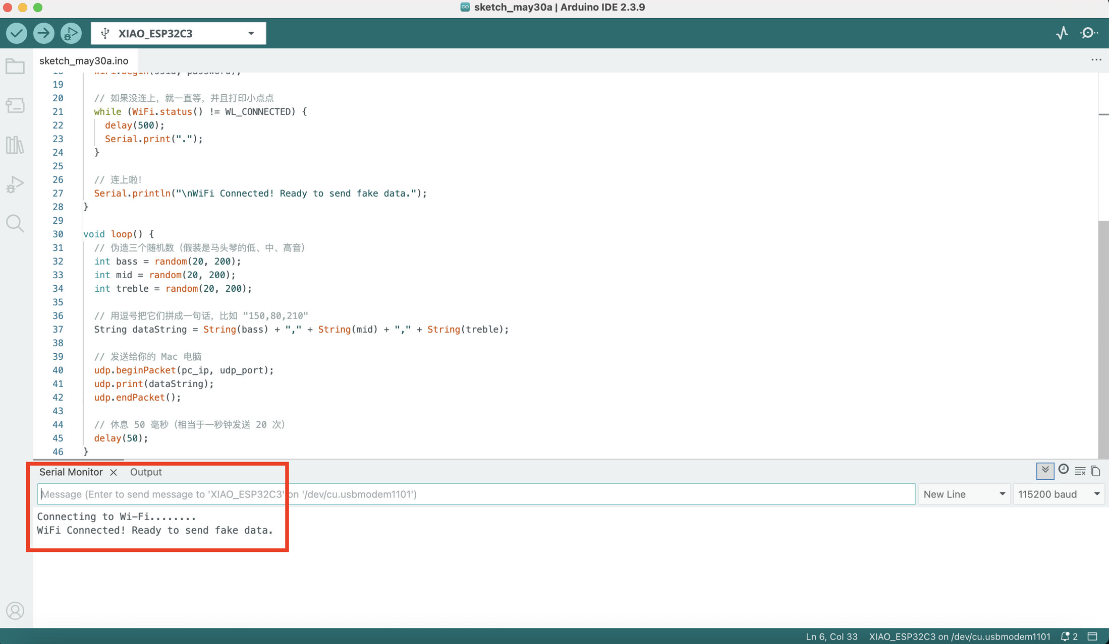
I ran the code and it's successfully connected to Wi-Fi and ready to send fake data.
The Receiver (Processing):
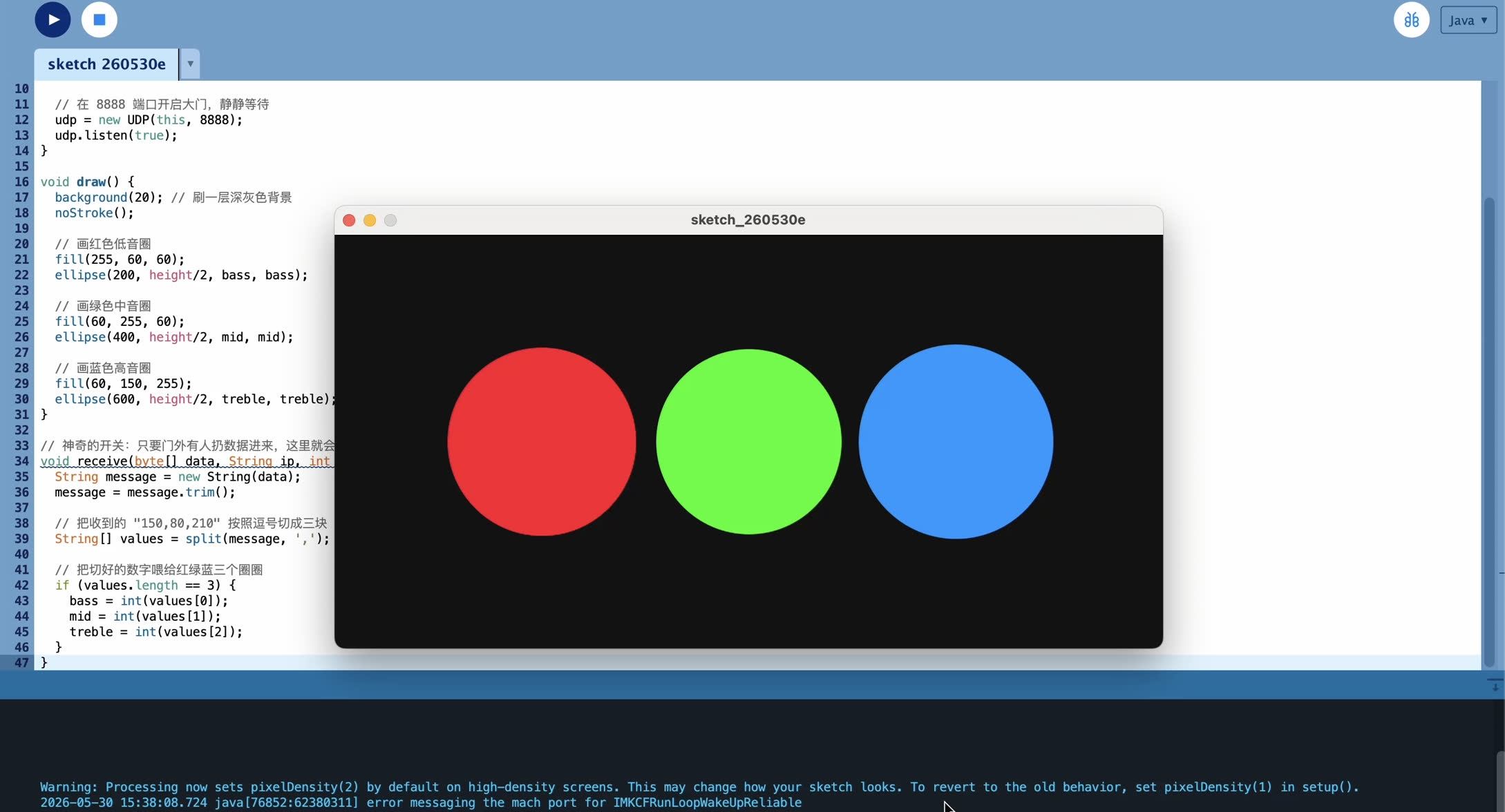
On the computer side, I used Processing with the hypermedia.net``.UDP library to act as the receiver. The initial dashboard was a simple diagnostic tool: three colored circles (Red, Green, Blue) that changed size based on the incoming string. Once I could see circles jumping, the wireless highway was successfully established.
Firstly, download Processing from the official website processing.org.
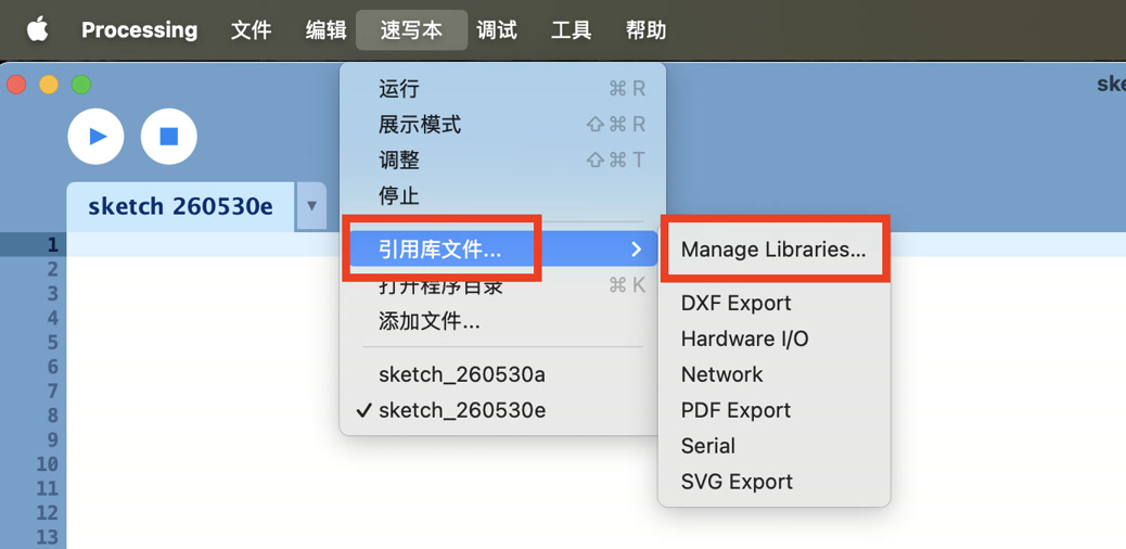
Sketch-->Import Library-->Manage Libraries,
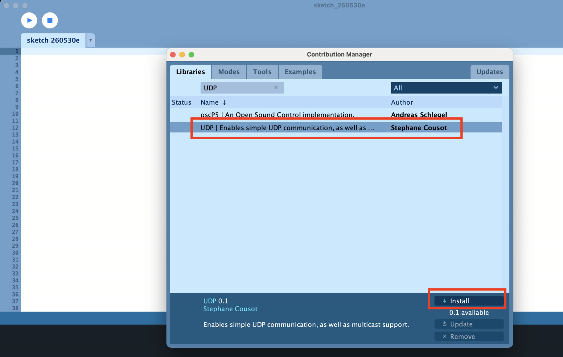
Select UDP by author Stephane Cousot and install it.
The First Visual (RGB Circles simulation): To visually verify the data, I mapped these three integers to the diameters of three simple circles colored Red, Green, and Blue. Then I ran the testing code below on Processing.
import hypermedia.net.*; // 召唤刚才安装的 UDP 插件

UDP udp;
int bass = 0;
int mid = 0;
int treble = 0;

void setup() {
  size(800, 400); // 弹出的黑板大小

  // 在 8888 端口开启大门,静静等待
  udp = new UDP(this, 8888);
  udp.listen(true);
}

void draw() {
  background(20); // 刷一层深灰色背景
  noStroke();

  // 画红色低音圈
  fill(255, 60, 60);
  ellipse(200, height/2, bass, bass);

  // 画绿色中音圈
  fill(60, 255, 60);
  ellipse(400, height/2, mid, mid);

  // 画蓝色高音圈
  fill(60, 150, 255);
  ellipse(600, height/2, treble, treble);
}

// 神奇的开关:只要门外有人扔数据进来,这里就会自动启动!
void receive(byte[] data, String ip, int port) {
  String message = new String(data);
  message = message.trim();

  // 把收到的 "150,80,210" 按照逗号切成三块
  String[] values = split(message, ',');

  // 把切好的数字喂给红绿蓝三个圈圈
  if (values.length == 3) {
    bass = int(values[0]);
    mid = int(values[1]);
    treble = int(values[2]);
  }
}
Once I saw the three circles successfully bouncing and changing sizes on my screen based on the random data, I mathematically proved that my wireless pipeline, IP configuration, and string parsing logic were 100% functional.
**Hardware-in-the-Loop Integration **
With the network verified, I merged the UDP transmitter into my main Morin Khuur program. Now, instead of generating random numbers, the ESP32C3 reads the live I2S audio stream, computes the FFT, categorizes the frequencies into Bass, Mid, and Treble energies, and maps them to a 0-255 scale.
To prevent the network transmission from blocking my local LED animations, I avoided using the delay() function. Instead, I used a millis() timer to ensure the UDP packet is fired exactly every 20 milliseconds (~50 FPS) asynchronously.
Arduino Code (Sender):
#include <Adafruit_NeoPixel.h>
#include <driver/i2s.h>
#include "arduinoFFT.h"
#include <WiFi.h>
#include <WiFiUdp.h>

// ================= Network Configuration (UDP) =================
/* * Connect the ESP32C3 to a 2.4GHz local network.
 * Ensure the computer running Processing is on the same network.
 */
const char* ssid = "Xiaomi 12S Ultra";
const char* password = "13572468";
const char* pc_ip = "192.168.183.102·";
const int udp_port = 8888;
WiFiUDP udp;

unsigned long lastUdpSendTime = 0;
const int udpInterval = 50; // Send packet every 50ms (20Hz)

// ================= Hardware Pin Configuration =================
#define LED_PIN     9
#define NUMPIXELS   160
Adafruit_NeoPixel strip(NUMPIXELS, LED_PIN, NEO_GRB + NEO_KHZ800);

#define I2S_PORT    I2S_NUM_0
#define I2S_SCK     D0
#define I2S_WS      D1
#define I2S_SD      D2

// ================= FFT Audio Processing Parameters =================
const uint16_t samples = 256;
const double samplingFrequency = 16000;
double vReal[samples];
double vImag[samples];

ArduinoFFT<double> FFT = ArduinoFFT<double>(vReal, vImag, samples, samplingFrequency);

void setup() {
  Serial.begin(115200);

  // 1. Initialize Network Connection
  Serial.print("Connecting to Wi-Fi...");
  WiFi.begin(ssid, password);
  while (WiFi.status() != WL_CONNECTED) {
    delay(500);
    Serial.print(".");
  }
  Serial.println("\nWiFi Connected! UDP Ready.");

  // 2. Initialize LED strip
  strip.begin();
  strip.setBrightness(20);
  strip.clear();
  strip.show();

  // 3. Configure I2S Microphone
  i2s_config_t i2s_config = {
    .mode = (i2s_mode_t)(I2S_MODE_MASTER | I2S_MODE_RX),
    .sample_rate = samplingFrequency,
    .bits_per_sample = I2S_BITS_PER_SAMPLE_32BIT,
    .channel_format = I2S_CHANNEL_FMT_ONLY_LEFT,
    .communication_format = I2S_COMM_FORMAT_STAND_I2S,
    .intr_alloc_flags = ESP_INTR_FLAG_LEVEL1,
    .dma_buf_count = 8,
    .dma_buf_len = 64,
    .use_apll = false
  };

  i2s_pin_config_t pin_config = {
    .bck_io_num = I2S_SCK,
    .ws_io_num = I2S_WS,
    .data_out_num = I2S_PIN_NO_CHANGE,
    .data_in_num = I2S_SD
  };

  i2s_driver_install(I2S_PORT, &i2s_config, 0, NULL);
  i2s_set_pin(I2S_PORT, &pin_config);
}

void loop() {
  // 1. Capture Audio Data
  size_t bytesIn = 0;
  int32_t sampleBuffer[samples];
  i2s_read(I2S_PORT, &sampleBuffer, sizeof(sampleBuffer), &bytesIn, portMAX_DELAY);

  int samplesRead = bytesIn / sizeof(int32_t);
  double totalVolume = 0;

  // 2. Data Cleaning
  for (int i = 0; i < samplesRead; i++) {
    int16_t audioValue = sampleBuffer[i] >> 14;
    vReal[i] = audioValue;
    vImag[i] = 0.0;
    totalVolume += abs(audioValue);
  }

  int averageVolume = totalVolume / samplesRead;

  // 3. Execute Fast Fourier Transform (FFT)
  FFT.windowing(FFT_WIN_TYP_HAMMING, FFT_FORWARD);
  FFT.compute(FFT_FORWARD);
  FFT.complexToMagnitude();

  // 4. Analyze Frequency Band Energy
  long bassEnergy = 0, midEnergy = 0, trebleEnergy = 0;
  for (int i = 2; i < (samplesRead / 2); i++) {
    if (i < 10) bassEnergy += vReal[i];
    else if (i < 40) midEnergy += vReal[i];
    else trebleEnergy += vReal[i];
  }

  // Variables for Visualizer and UDP
  int r = 0, g = 0, b = 0;
  strip.clear();

  // 5. Map Data to the LED Strip & Extract RGB Data
  if (averageVolume > 400) {
    int ledsToLight = map(averageVolume, 400, 8000, 1, NUMPIXELS / 2);
    if (ledsToLight > NUMPIXELS / 2) ledsToLight = NUMPIXELS / 2;

    r = map(bassEnergy, 0, 50000, 0, 255);
    g = map(midEnergy, 0, 30000, 0, 255);
    b = map(trebleEnergy, 0, 20000, 0, 255);

    r = constrain(r, 0, 255);
    g = constrain(g, 0, 255);
    b = constrain(b, 0, 255);

    int center = NUMPIXELS / 2;
    for (int i = 0; i < ledsToLight; i++) {
      strip.setPixelColor(center + i, strip.Color(r, g, b));
      strip.setPixelColor(center - 1 - i, strip.Color(r, g, b));
    }
  }
  strip.show();

  // 6. Non-blocking UDP Data Transmission
  unsigned long currentTime = millis();
  if (currentTime - lastUdpSendTime >= udpInterval) {
    lastUdpSendTime = currentTime;

    // Construct data packet format: "Bass,Mid,Treble"
    String dataString = String(r) + "," + String(g) + "," + String(b);

    udp.beginPacket(pc_ip, udp_port);
    udp.print(dataString);
    udp.endPacket();
  }
}
Processing Code (Receiver):
import hypermedia.net.*; // Import the UDP library

UDP udp;
int bass = 0;
int mid = 0;
int treble = 0;

void setup() {
  size(800, 400); // Set dashboard window size

  // Open port 8888 and listen for incoming packets from ESP32C3
  udp = new UDP(this, 8888);
  udp.listen(true);
}

void draw() {
  // Clear the background with a dark gray color each frame
  background(20);
  noStroke();

  // Draw Bass frequency indicator (Red)
  fill(255, 60, 60);
  ellipse(200, height/2, bass, bass);

  // Draw Mid frequency indicator (Green)
  fill(60, 255, 60);
  ellipse(400, height/2, mid, mid);

  // Draw Treble frequency indicator (Blue)
  fill(60, 150, 255);
  ellipse(600, height/2, treble, treble);
}

/**
 * Event Listener: Triggered automatically when a UDP packet arrives
 */
void receive(byte[] data, String ip, int port) {
  // Convert incoming raw bytes to string
  String message = new String(data);
  message = message.trim();

  // Parse the comma-separated values (e.g., "150,80,210")
  String[] values = split(message, ',');

  // Assign mapped RGB/Audio values to circle diameters
  if (values.length == 3) {
    bass = int(values[0]);
    mid = int(values[1]);
    treble = int(values[2]);
  }
}
RGB Circle Visual effect: