Week 9 - Input Devices
Group Assignment
The link to our group work: https://fabacademy.org/2026/labs/chaihuo/docs/week9/chaihuo/week9_group_assignment
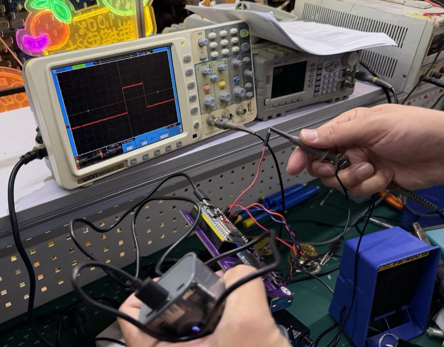
For this week's group assignment, we gathered around the lab's OWON EDS102 CV oscilloscope to actually visualize the electrical signals traveling across the custom ESP32 PCBs we fabricated in earlier weeks.
While I have used a multimeter before to check basic voltages, looking at signals on an oscilloscope was a completely different experience. Here are my biggest personal takeaways from our group probing sessions:
Demystifying PWM (Pulse Width Modulation) We hooked up the scope probe to a servo motor's control line. I always knew conceptually that PWM uses "duty cycles" to dictate position, but watching the physical square waves instantly expand and contract on the screen as we commanded the servo to move from -90° to 90° was a huge "Aha!" moment. We could physically measure the 20ms period (50Hz) and see the pulse width shift between roughly 1.0ms and 2.0ms. It made the abstract code incredibly tangible.
The Golden Rule of Grounding I learned very quickly that an oscilloscope is useless without a shared reference. In one of our early attempts, we forgot to connect the probe's alligator clip to the PCB's ground plane. The screen just showed a messy, floating "garbage" waveform. Tying the grounds together instantly snapped the signal into a clean, readable shape.
Taming the Trigger At first, the waveforms we probed were constantly drifting horizontally across the screen, making them impossible to read. I learned how to adjust the scope's trigger level so it sits directly inside the voltage swing (e.g., around 1.5V for our 3.3V logic). Once the trigger caught the edge, the waveform froze perfectly in place.
The Right Tool for the Job This exercise taught me the fundamental difference in troubleshooting: a multimeter tells you what the voltage level is, but a scope tells you how it gets there. It can reveal hidden hardware issues like contact bounce on a digital button or noisy edges on a sensor line.
How this informed my Individual Project
This hands-on scope training was directly applicable to my final project—the digital Morin Khuur. When I moved on to integrating my digital I2S microphone, I knew that if the ESP32 wasn't receiving audio data, I shouldn't just blindly stare at my C++ code. My first troubleshooting step would be to hook the oscilloscope up to the BCLK (Bit Clock) and WS (Word Select) pins to physically verify if the microphone was generating clean, square clock pulses on the physical PCB traces. Knowing how to verify the hardware layer first gave me massive confidence moving into the software integration.
Individual Assignment
Objective
The objective of this assignment is to design and implement an input device system that can read environmental data using a digital sensor and communicate the data to a microcontroller via the I2C protocol.
The system is required to:
- Detect and communicate with an I2C sensor
- Read real-time temperature and humidity values
- Output data through serial communication
- Demonstrate understanding of embedded communication protocols
System Overview
This project uses the following components:
- ESP32-C3 microcontroller
- SHT40 temperature and humidity sensor
- USB connection for serial output
The communication structure is based on the I2C protocol, where:
- The ESP32-C3 acts as the master device
- The SHT40 sensor acts as an I2C slave device
- Each device is identified using a unique I2C address
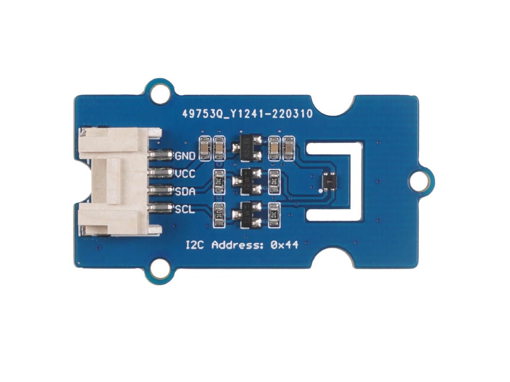
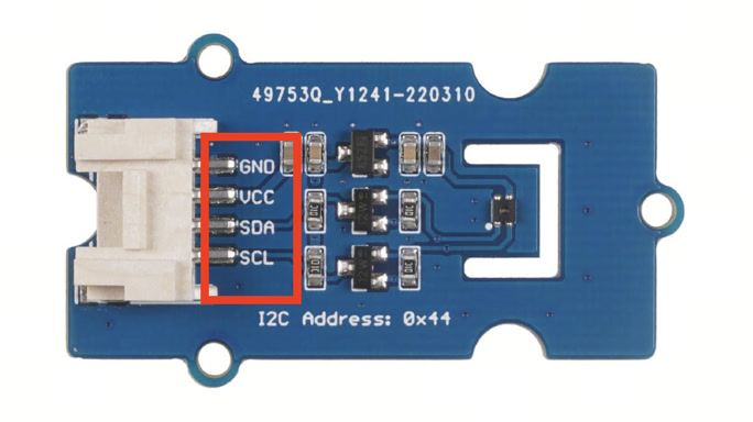
In this system, the SHT40 sensor is detected at address 0x44.
About Grove SHT40 temperature and humidity sensor:
Grove - Temperature & Humidity Sensor (SHT40) is a digital Humidity and Temperature Sensor which has an accuracy rate of up to ±1.8% ~ ±3.5% RH and ±0.2 °C, and an operating range of 0% to 100% RH, -40°C to +125°C. It comes with a SEEED's standard grove I2C interface enabling developers or even beginners to easily communicate with the SHT40 sensor on different hardware platforms, for a wide variety of applications, such as Climate Monitoring, Smart Home, etc.
Specifications:
- Temperature accuracy rate | ±0.2 ℃
- Typical Humidity accuracy rate | ±1.8% RH
- Maximum Relative Humidity Accuracy Rate | ±3.5%
- Operating temperature range | -40°C to 125°C
- Operating Humidity range | 0% to 100% RH
- Grove power supply | 5/3.3 volts
- Serial Protocol | I2C
- Grove's average current supply | 1.2 µA
- Grove idle current | 32µA
- Product Dimension | 20mm x 40mm
Why I2C is used
I2C was selected for this project because:
- It only requires two communication lines (SDA and SCL)
- Multiple devices can share the same bus
- Each device is identified by a unique address
- It is widely supported by sensors and microcontrollers
In this project, the I2C bus simplifies wiring and allows reliable communication between the ESP32-C3 and the SHT40 sensor.
Hardware Setup
Components used
- XIAO ESP32-C3 development board
- Grove SHT40 temperature and humidity sensor
- Jumper wires
- USB cable
Wiring configuration
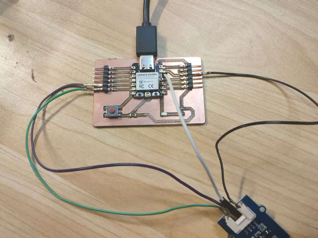
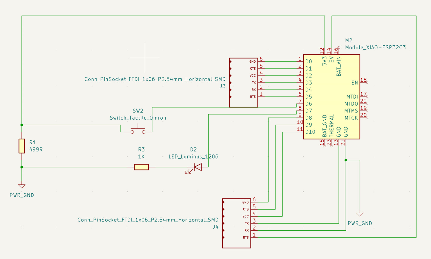
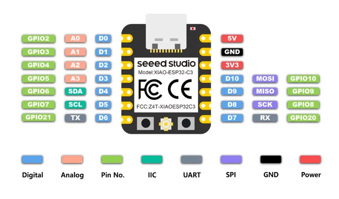
Before Wiring, I reviewed the pin definition of my designed board with XIAO ESP32C3 as well as the Grove SHT40 temperature and humidity sensor.
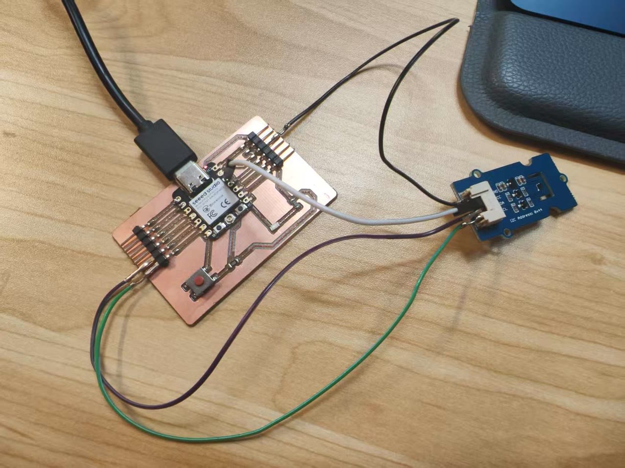
The Grove - SHT40 sensor is connected as follows:
- VCC → 3.3V power supply
- GND → Ground
- SDA → I2C data line (SDA pin on XIAO ESP32-C3)
- SCL → I2C clock line (SCL pin on XIAO ESP32-C3)
I found one problem—from the schematic I designed, there is no extra socket pin for 3.3V on XIAO ESP32C3. So, I used a particular jumper wire to connect the original 3.3V on XIAO then connect to the SHT40 temperature & humidity sensor's VCC pin.
Why these connections are used
- The Grove SHT40 sensor operates at 3.3V logic level, so it must not be connected to 5V
- SDA is used for transmitting data between devices
- SCL provides synchronization for data transmission
- ESP32-C3 supports flexible I2C pin assignment depending on board configuration
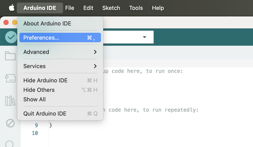
Arduino IDE Setup & Programming
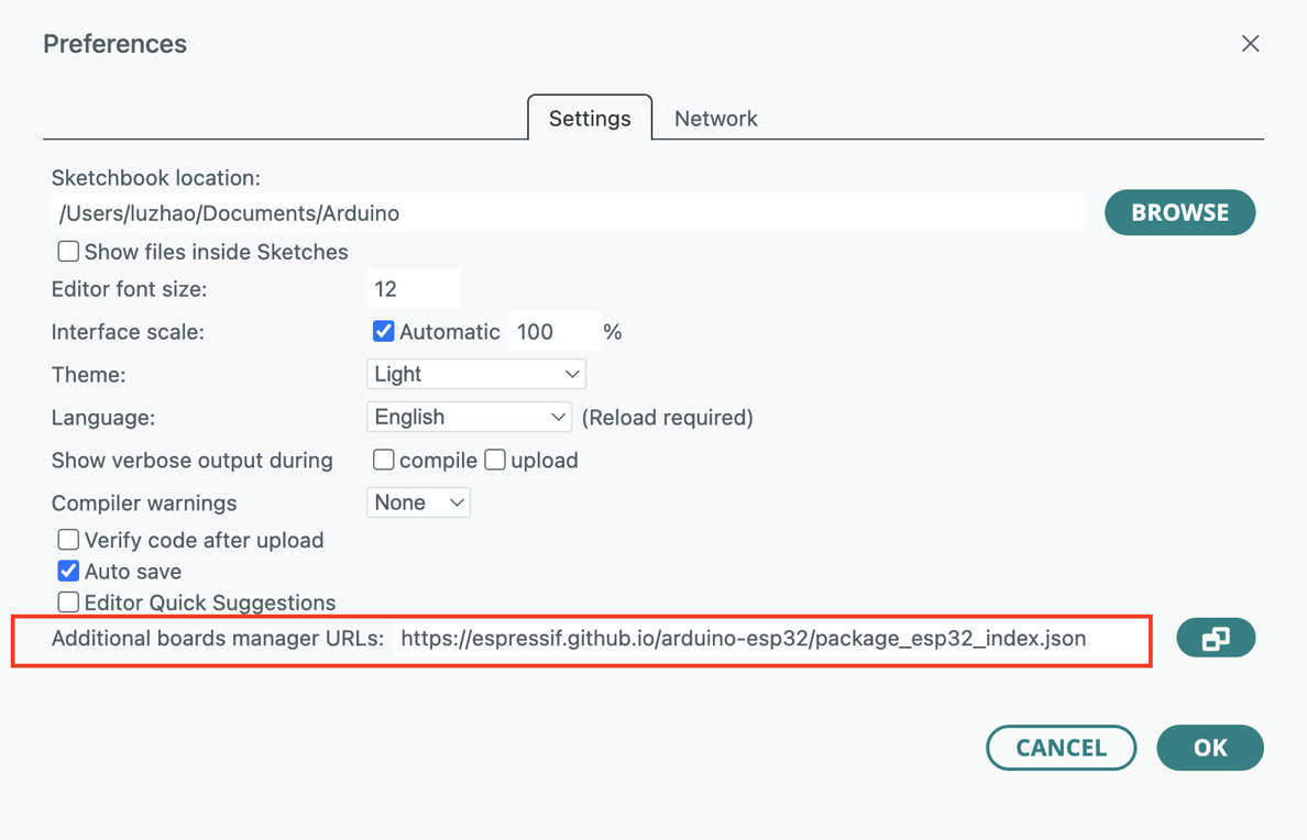
Step 1 – Install ESP32 board package
The ESP32 board package is added to Arduino IDE by inserting the following URL into the additional board manager field: https://espressif.github.io/arduino-esp32/package_esp32_index.json
This allows Arduino IDE to recognize ESP32 boards.
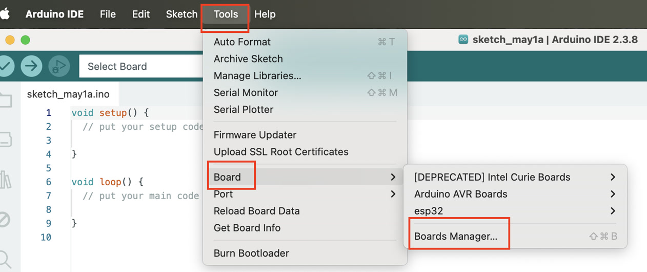
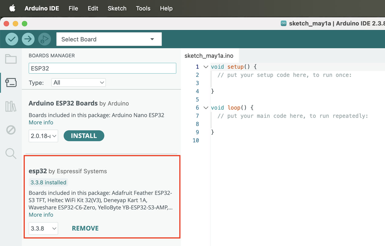
Step 2 – Install board support
After adding the URL, the ESP32 package is installed from the Board Manager by searching for "ESP32 by Espressif Systems". I double checked and found it's already installed before.
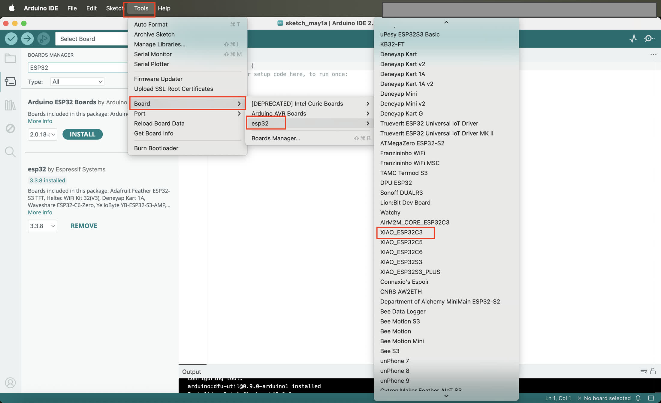
Step 3 – Select board
The correct board selection is: XIAO_ESP32C3
This ensures correct pin mapping and USB behavior for Seeed XIAO hardware.
Step 4: Hardware Connection Test
Before any I2C or sensor testing, basic hardware connectivity is verified.
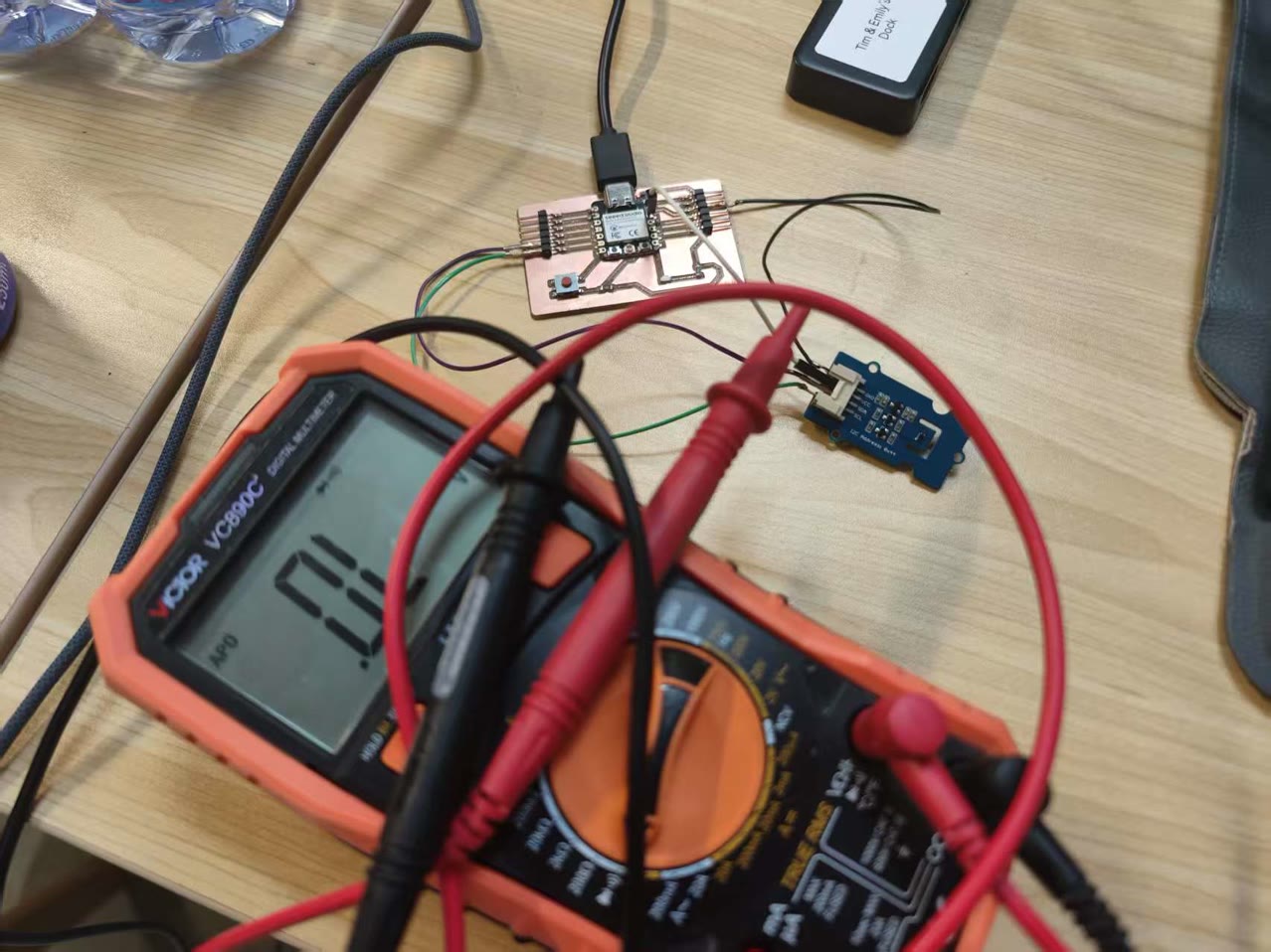
I used the multimeter again to test if all the connections on board is working well.
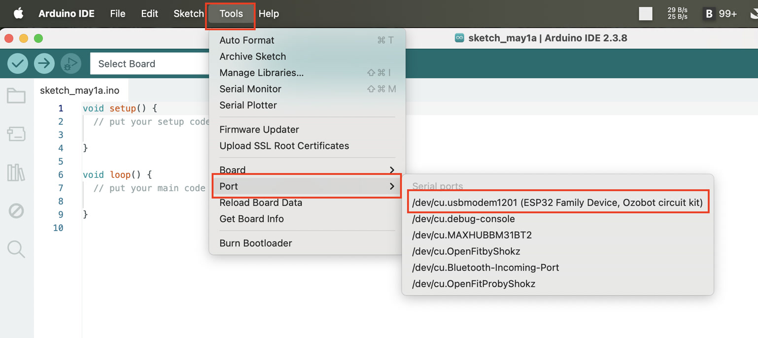
I go to Tools → Port, and confirm device appears as: /dev/cu.usbmodemXXXX
Step 5: Basic Serial Test (Firmware Validation)
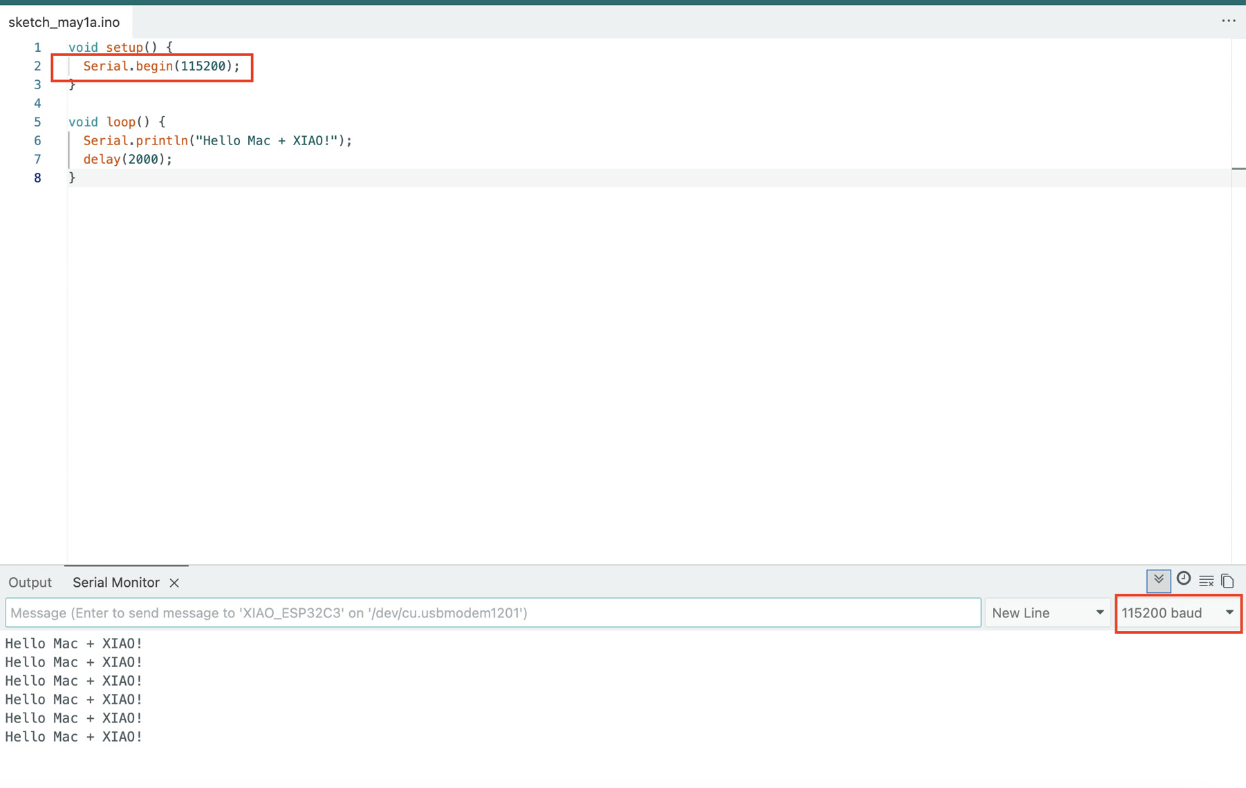
This step ensures the board itself is functioning before using I2C, by confirming firmware upload works and Serial Monitor works. I intended to print simple "Hello" or boot message, and verified stable serial communication at 115200 baud.
void setup() {
  Serial.begin(115200);
}

void loop() {
  Serial.println("Hello Mac + XIAO!");
  delay(2000);
}
Then I can see the "Hello Mac + XIAO" from the Serial Monitor.
STEP 6 – I2C Device Scan
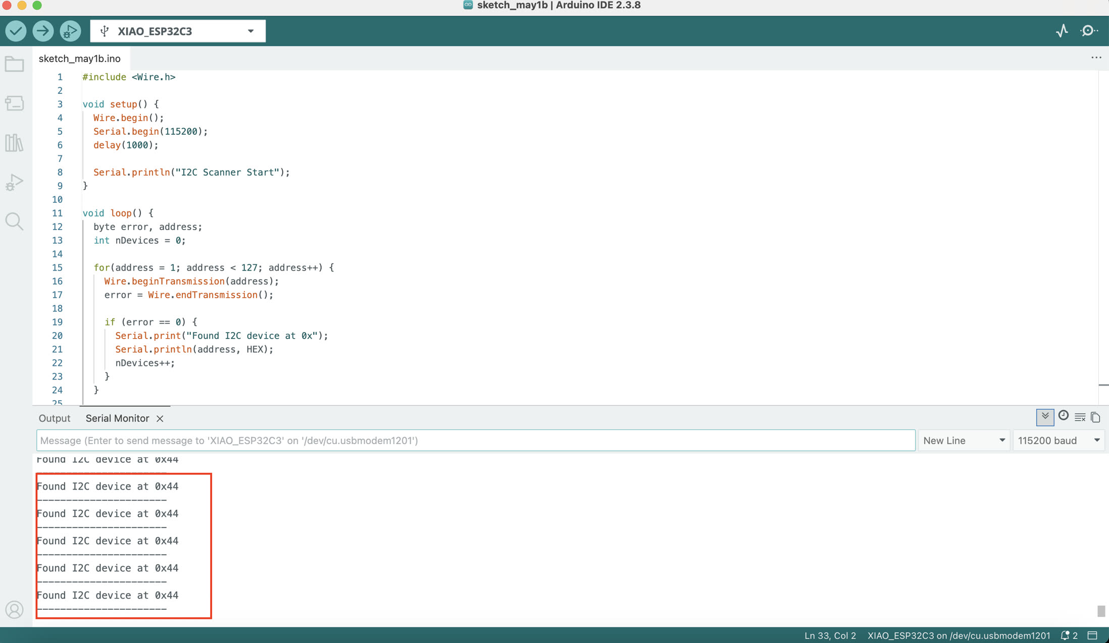
Now I verify that the sensor is visible on the I2C bus. The code is generated by ChatGPT:
#include <Wire.h>

void setup() {
  Wire.begin();
  Serial.begin(115200);
  delay(1000);

  Serial.println("I2C Scanner Start");
}

void loop() {
  byte error, address;
  int nDevices = 0;

  for(address = 1; address < 127; address++) {
    Wire.beginTransmission(address);
    error = Wire.endTransmission();

    if (error == 0) {
      Serial.print("Found I2C device at 0x");
      Serial.println(address, HEX);
      nDevices++;
    }
  }

  if (nDevices == 0) {
    Serial.println("No I2C devices found");
  }

  Serial.println("----------------------");

  delay(3000);
}
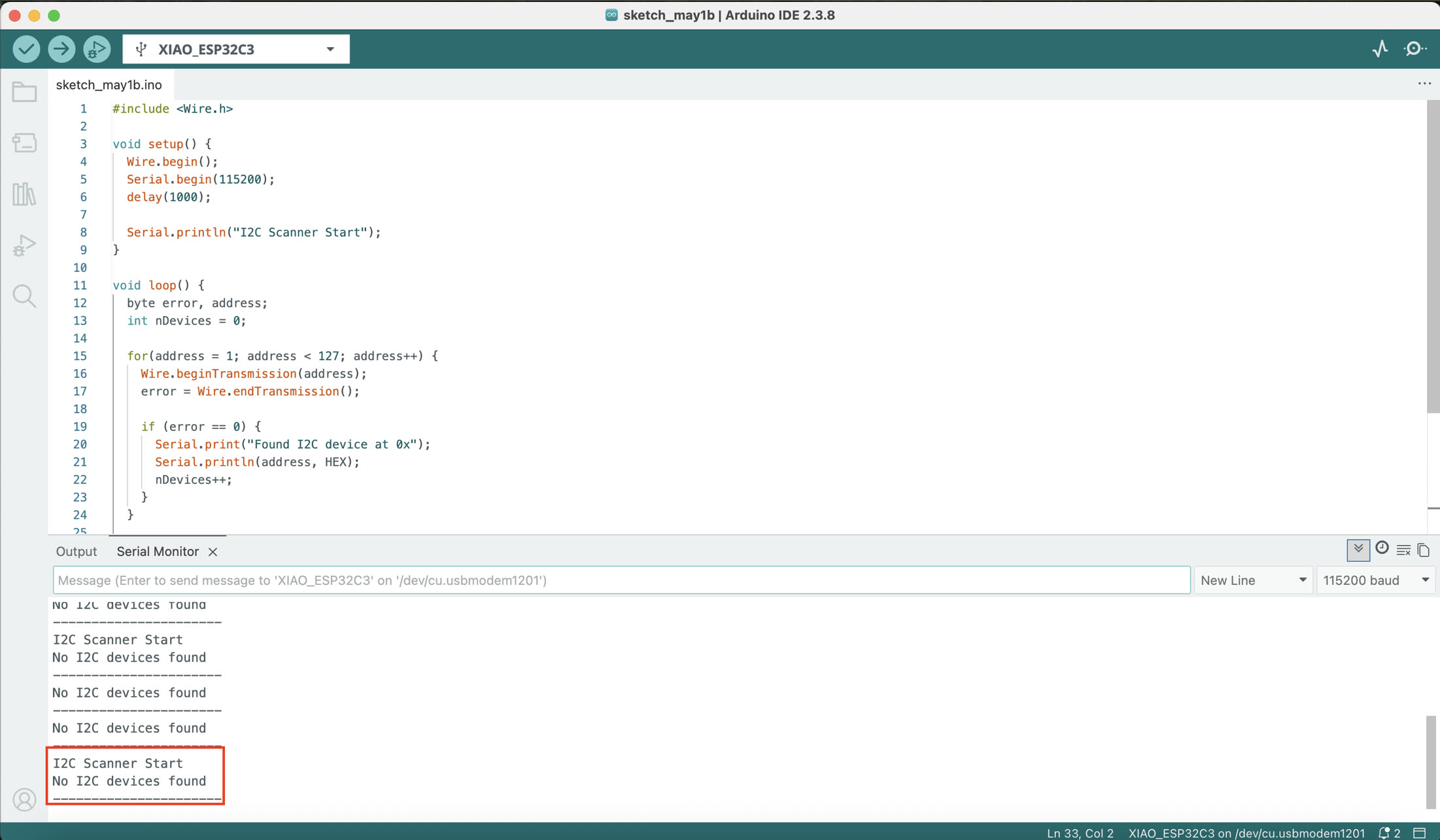
I double checked if the USB connection or the pin connection is correct; or if the wiring of jumper wire is too loose. After checking, it's because the jumper wire too loose, I reconnected them and I can see the positive result on Serial Monitor.
The sensor is detected at: 0x44
STEP 7 – Sensor Data Acquisition
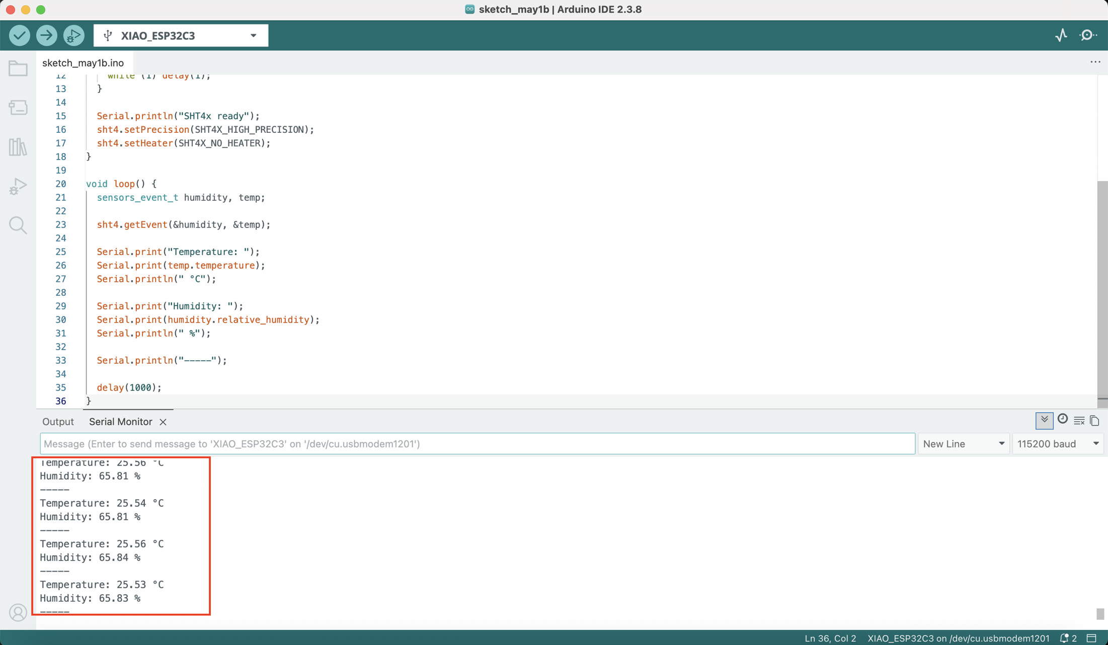
After all validation steps, I used the code below to initialize the SHT40 sensor to show me temperature and humidity. The code below is generated by ChatGPT.
#include <Wire.h>
#include "Adafruit_SHT4x.h"

Adafruit_SHT4x sht4 = Adafruit_SHT4x();

void setup() {
  Serial.begin(115200);
  Wire.begin();   // ESP32-C3 default I2C pins

  if (!sht4.begin()) {
    Serial.println("SHT4x not found!");
    while (1) delay(1);
  }

  Serial.println("SHT4x ready");
  sht4.setPrecision(SHT4X_HIGH_PRECISION);
  sht4.setHeater(SHT4X_NO_HEATER);
}

void loop() {
  sensors_event_t humidity, temp;

  sht4.getEvent(&humidity, &temp);

  Serial.print("Temperature: ");
  Serial.print(temp.temperature);
  Serial.println(" °C");

  Serial.print("Humidity: ");
  Serial.print(humidity.relative_humidity);
  Serial.println(" %");

  Serial.println("-----");

  delay(1000);
}
The system reads: Temperature (°C) & Humidity (%). The data is updated every 1 second via Serial Monitor.
Summary
In this assignment, I developed and tested an input device system using the Seeed Studio XIAO ESP32C3 and a Grove SHT40 temperature and humidity sensor. The system was built using the I2C communication protocol, where the microcontroller acts as the master device and the sensor operates as a slave device with the address 0x44.
The workflow started with basic hardware and software setup in Arduino IDE, including installing the ESP32 board package and required sensor libraries. Before reading sensor data, I verified system stability through hardware connection checks and serial communication tests. I then used an I2C scanner to confirm that the sensor was correctly detected on the bus.
After successful detection, the Adafruit SHT4x library was used to initialize the sensor and retrieve real-time environmental data. The system continuously outputs temperature and humidity values through the Serial Monitor at a 1-second interval.
This exercise demonstrates a complete embedded input device workflow, including hardware setup, communication verification, sensor integration, and real-time data acquisition using I2C.