Week 5: 3D Scanning and Printing
This week’s tasks are split into two parts. The group assignment involves characterizing our local 3D printers by testing their limits in areas like clearance, overhangs, and dimensional accuracy. The individual assignment focuses on designing and printing a complex object that cannot be made with subtractive methods, as well as 3D scanning a physical object for digital reproduction.
Principles of 3D Printing3D printing, or Additive Manufacturing, creates objects by stacking material layer by layer from a digital model. Unlike traditional CNC milling that carves material away, a 3D printer only deposits material where needed. A "slicer" software converts the CAD design into horizontal layers, guiding the printer to melt and extrude plastic filament through a heated nozzle. Because the process builds from the bottom up, designers must account for gravity by adding temporary support structures for parts that hang over empty space.
Materials and FilamentsThe "ink" for 3D printing comes in spools of plastic filament, with the choice depending on the project’s needs. PLA (Polylactic Acid) is the most common choice; it is plant-based, easy to print, and ideal for visual models. For functional parts requiring higher durability and heat resistance, ABS is often used, though it requires more temperature control. Other specialized materials include PETG, which balances strength and ease of use, and TPU, which is flexible and rubbery. Matching the filament to the intended use of the part is essential for a successful print.
Group Assignment
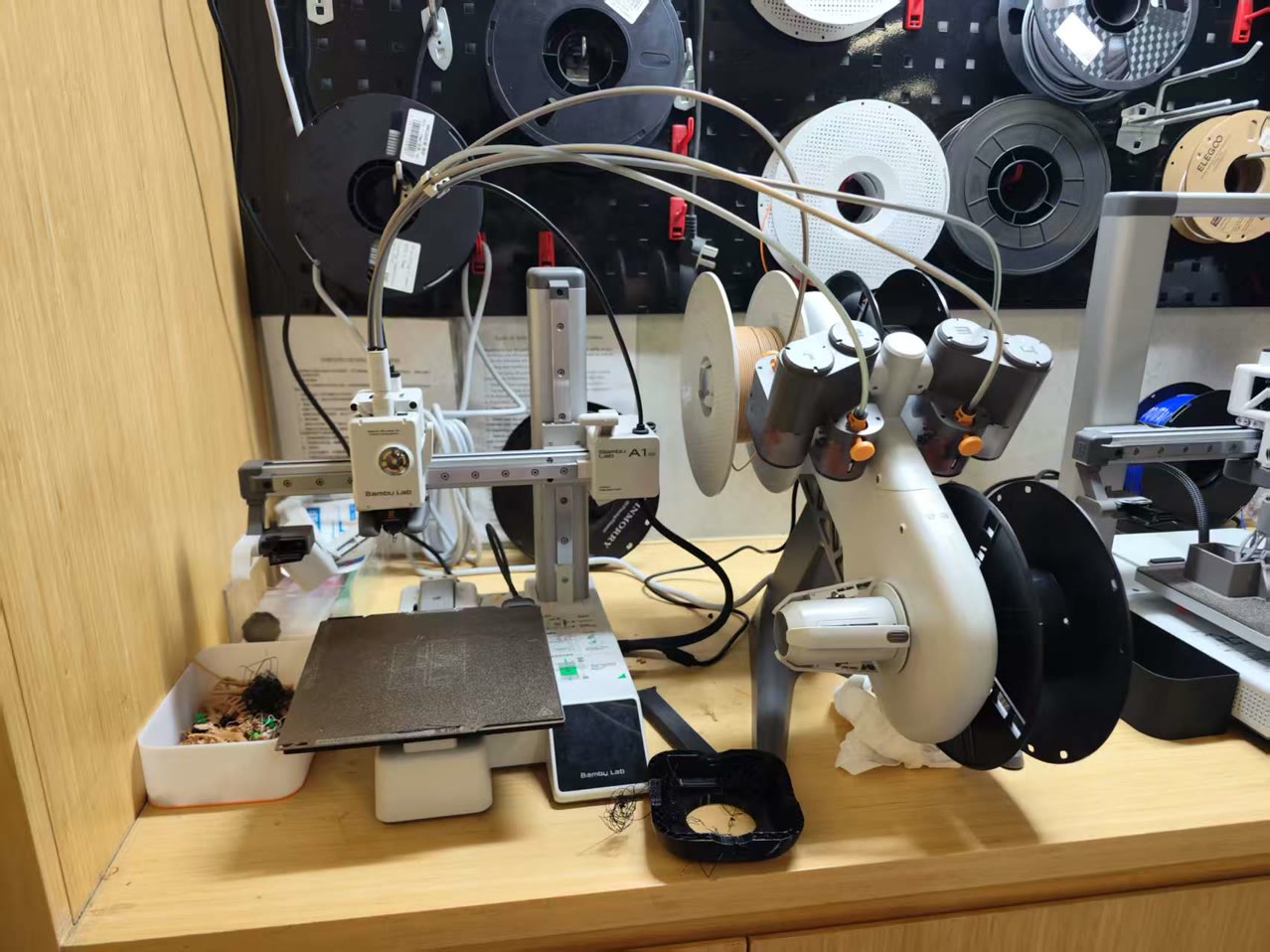
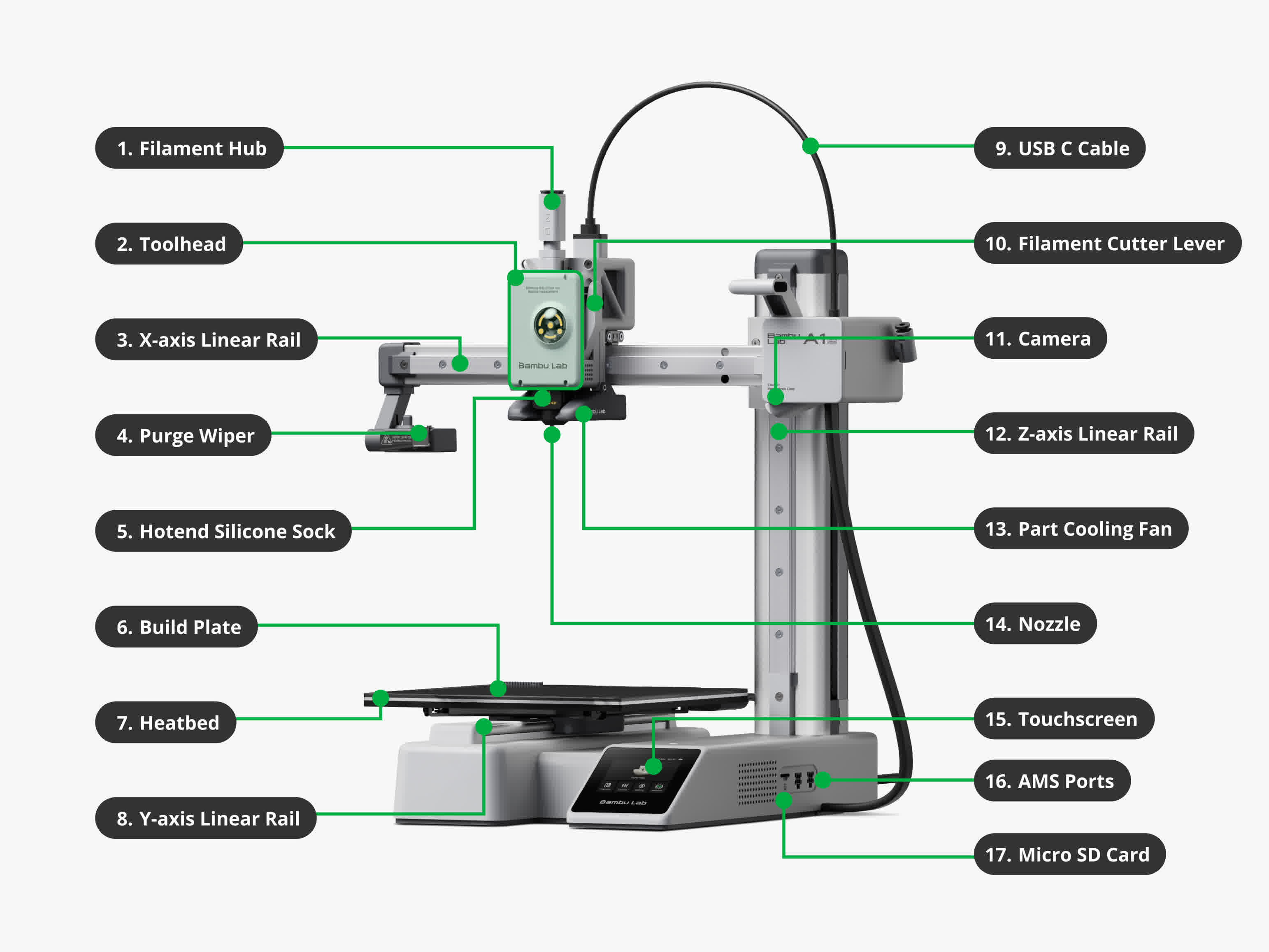
There are several 3D printers Chaihuo Makerspace, and we used Bambu Lab A1 Mini for our group work, it is also equipped with the Automatic Material System (AMS) Lite.
Build Volume: 180 x 180 x 180 mm³.
Max Speed: 500 mm/s with an acceleration of up to 10,000 mm/s², significantly reducing print time for test samples.
Active Flow Rate Compensation: Uses a high-frequency eddy current sensor to measure nozzle pressure, ensuring consistent extrusion.
Full Auto-Calibration: Automatically handles Z-offset, bed leveling, and vibration suppression before each print.
Toolhead: Features a quick-swap nozzle design and an all-metal hotend capable of reaching 300°C.
Filament Compatibility: Optimized for PLA, PETG, TPU, and PVA (support material), making it versatile for both aesthetic and functional prototypes.
The AMS Lite is an external unit that manages up to four filament spools simultaneously.
Multi-Material: Enables automatic filament switching for multi-color prints or using specialized support materials (like dissolvable PVA).
Filament Backup: Automatically switches to a backup spool if the current one runs out, preventing print failures.
RFID Sync: Automatically identifies filament types and colors for seamless software integration.
Design Rules Testing for Bambu Lab A1 Mini
We ran these tests to see what our printer can and cannot do. It’s basically about knowing the machine's limits so we don’t waste time and filament on designs that will just fail.
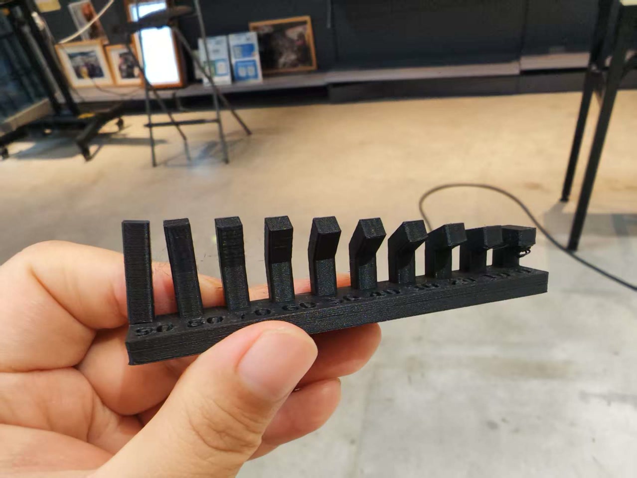
Angle Test This is to see how clean a sloped surface looks. We wanted to find the point where the "staircase" effect on the side becomes too rough or messy to use.
Overhang Test This is a gravity test. We checked how far the printer can lean out into the air before the plastic starts to sag or the whole structure falls apart.
Clearance Test If we want to print parts that move, like a hinge, we need a small gap so they don't stick together. We tested different gaps to see which one lets the parts move freely after printing.
Bridging Test This is when the nozzle has to extrude plastic across a gap between two points. We measured how long this gap can be before the plastic strands start dropping in the middle.
Wall Thickness Test This tells us the thinnest wall we can design. If the wall is too thin, the part will be too weak or the printer might not even be able to form it at all.
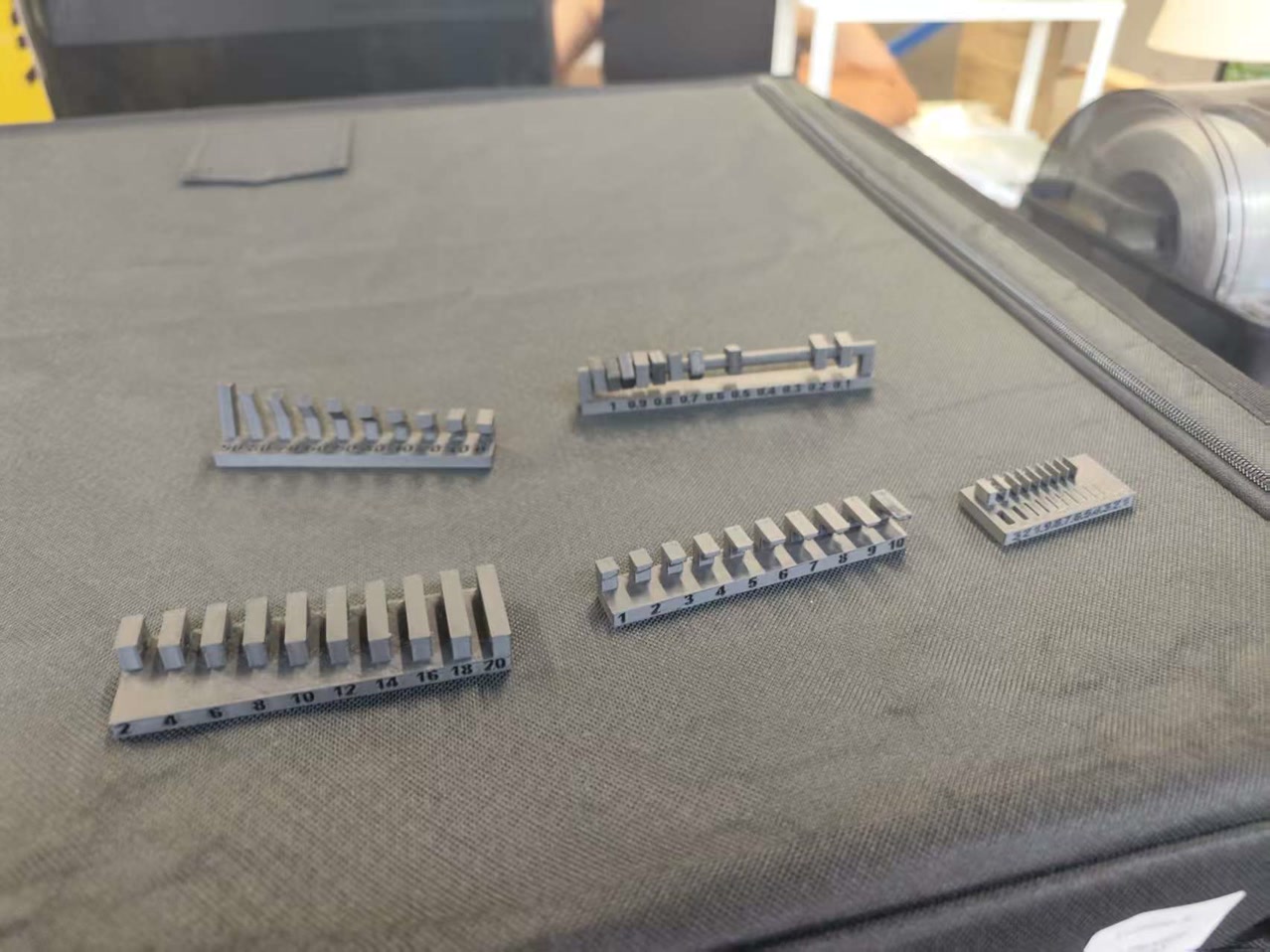
1. Angle Test
Good print quality was achieved for angles between 90° and 20°. But when the angle was reduced to 10° or 0°, the string waste appeared underneath the tilted surface.
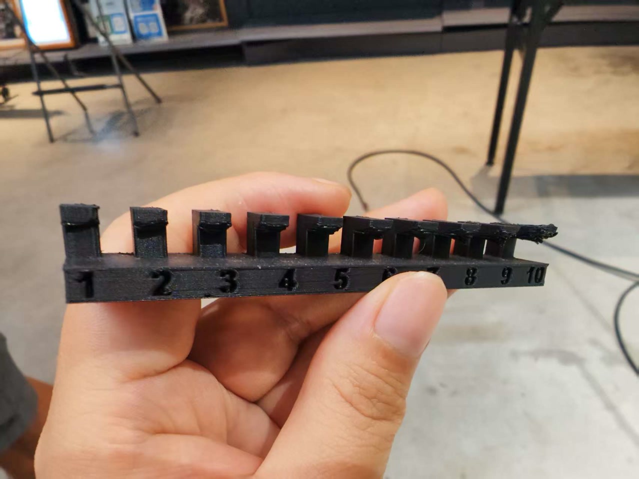
2. Overhang Test
A 1 mm overhang remains acceptable in appearance. Overhangs ranging from 2 mm to 5 mm appear somewhat uneven. For overhangs between 6 mm and 10 mm, significant stringiness and abundant “spaghetti” are observed.
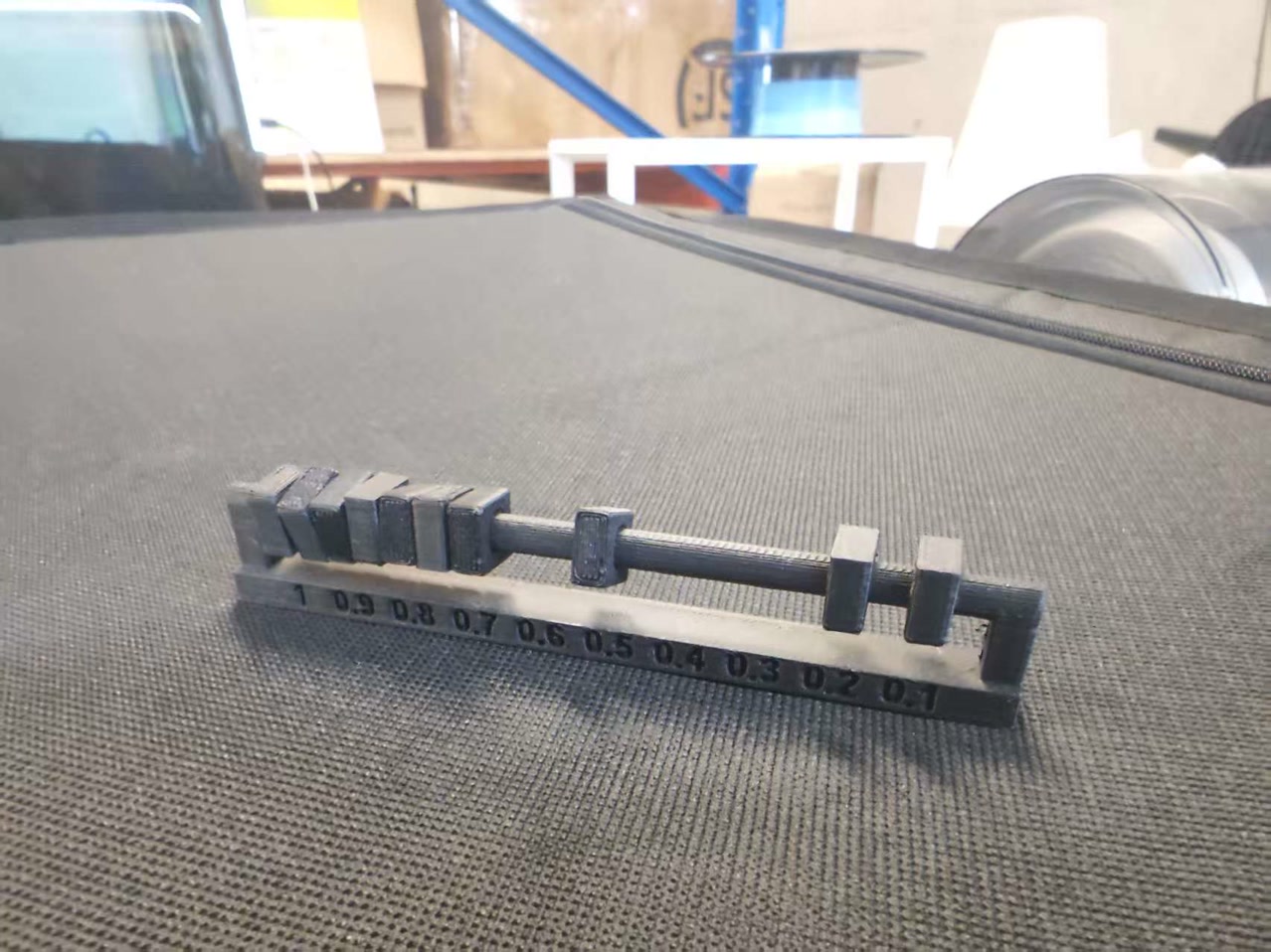
3. Clearance Test
For clearances ranging from 0.4 mm to 1 mm, free movement along the track is achievable. At 0.3 mm, movement is limited to only halfway. At 0.1 mm and 0.2 mm, no movement is possible at all.
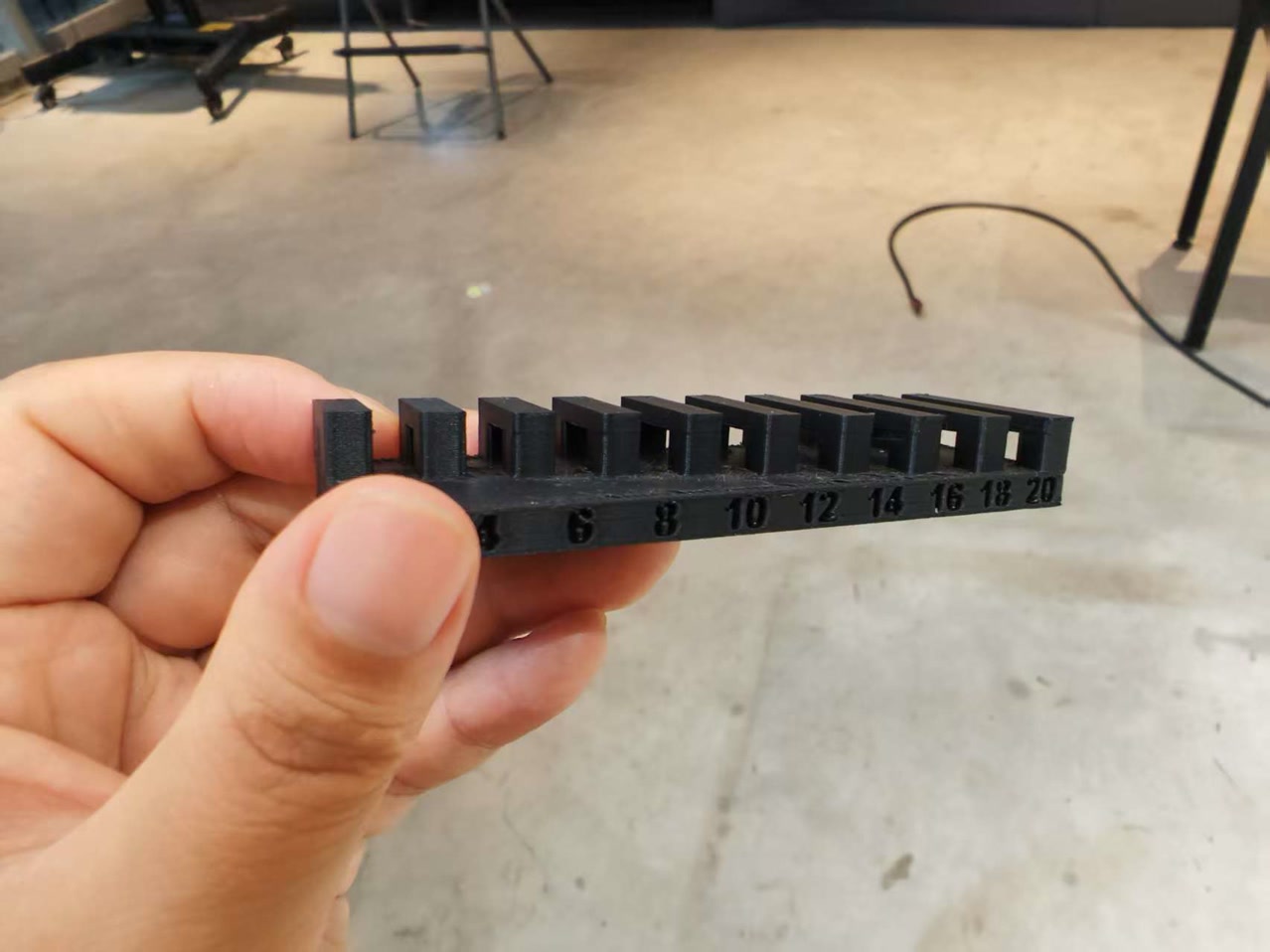
4. Bridging Test
For bridge lengths from 2 mm up to 20 mm, the structures remain solid, and no spaghetti is observed at all.
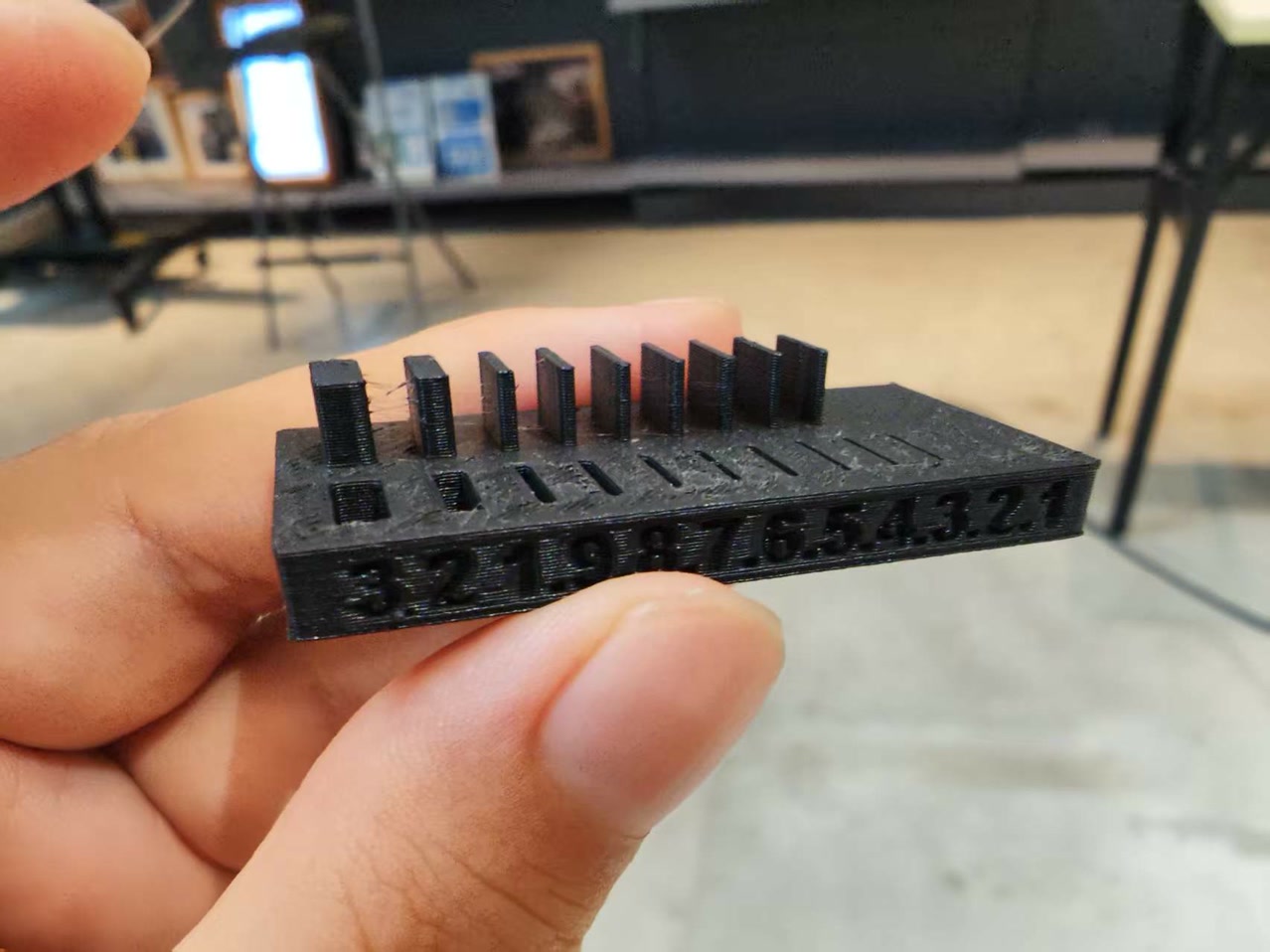
5. Wall Sickness Test
With a nozzle diameter of 0.4 mm, the minimum achievable printed wall thickness is 0.4 mm. Thicknesses of 0.1 mm, 0.2 mm, and 0.3 mm could not be successfully printed.
Individual Assignment
Core Concepts
In the world of fabrication, there are two primary but opposing approaches:
- Subtractive Manufacturing (e.g., CNC Milling): This process starts with a solid block of material and involves cutting, carving, or drilling away layers until the final shape is achieved. It is highly precise but limited by the physical reach of the cutting tool; a drill bit cannot easily carve complex internal cavities without destroying the outer shell.
- Additive Manufacturing (e.g., 3D Printing): Unlike cutting away material, this process builds an object layer by layer from the bottom up. Material is only placed where it is needed, allowing for the creation of intricate internal geometries that are impossible to reach with traditional tools.
1. 3D Printing
Design Concept
The core objective is to demonstrate additive manufacturing capabilities by creating an object that is "un-millable" through subtractive methods. I designed a Captive Ball in a Cube 30mm cage with an 18mm internal sphere). This project features a nested geometry where the internal part is larger than the external openings, a task impossible for traditional CNC tools.
Detailed Modeling Process (Onshape)
Phase A: Modeling the Cage
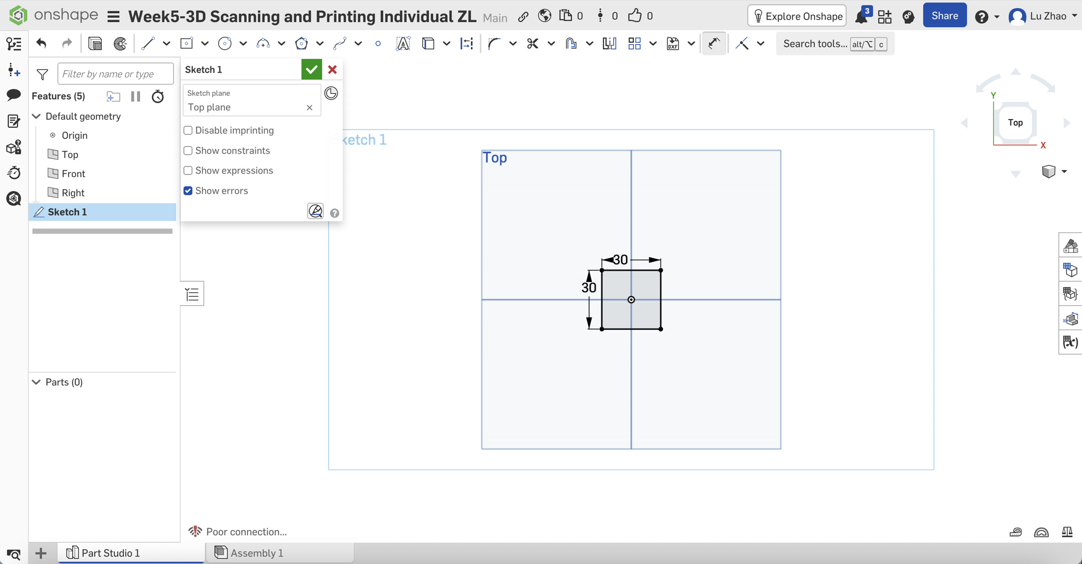
Start a Sketch: Click on the Top Plane and select Sketch from the top toolbar.
Draw the Base: Select Center Point Rectangle. Click the center origin (0,0) and drag outwards. Use the Dimension tool to set both sides to 30mm.
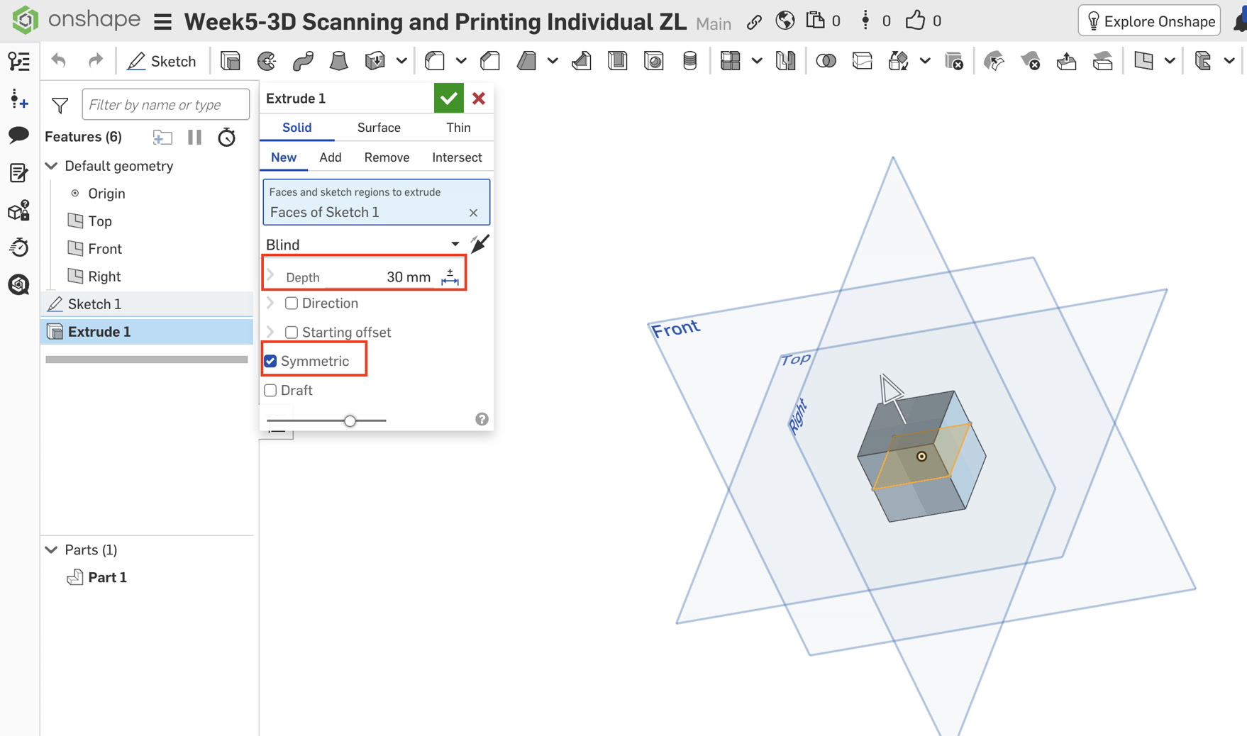
Symmetric Extrude: Click Extrude, and set the dropdown to Symmetric, and then Set Depth to 30mm.
Why Symmetric? This keeps the origin (0,0,0) at the exact center of the cube, which is vital for the next steps.
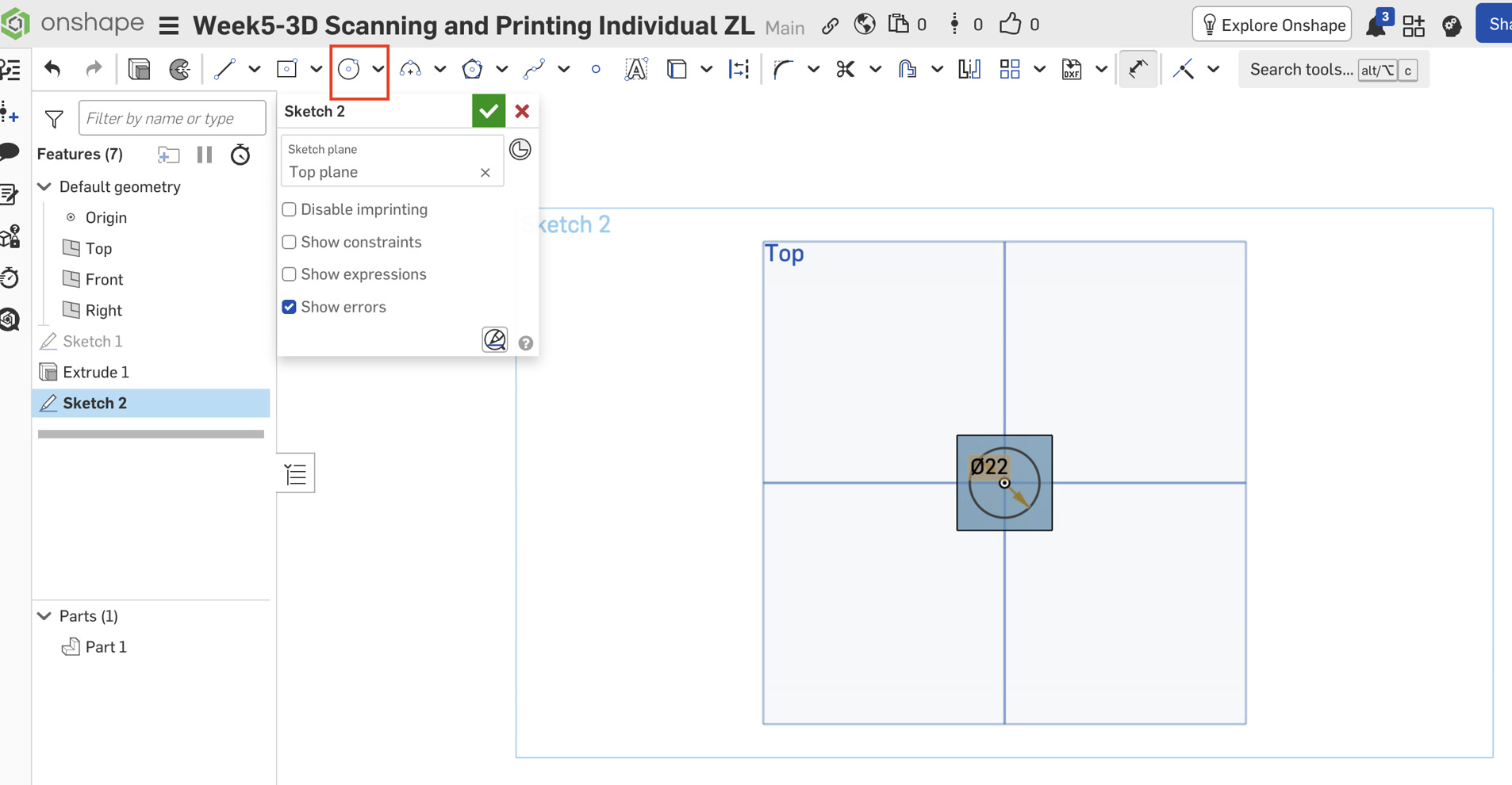
Create Apertures (Circular Holes):
Select the Front Plane and start a new Sketch. Draw a 22mm circle at the origin.
Click Extrude, select Remove, change the dropdown to Through All, and check Symmetric.
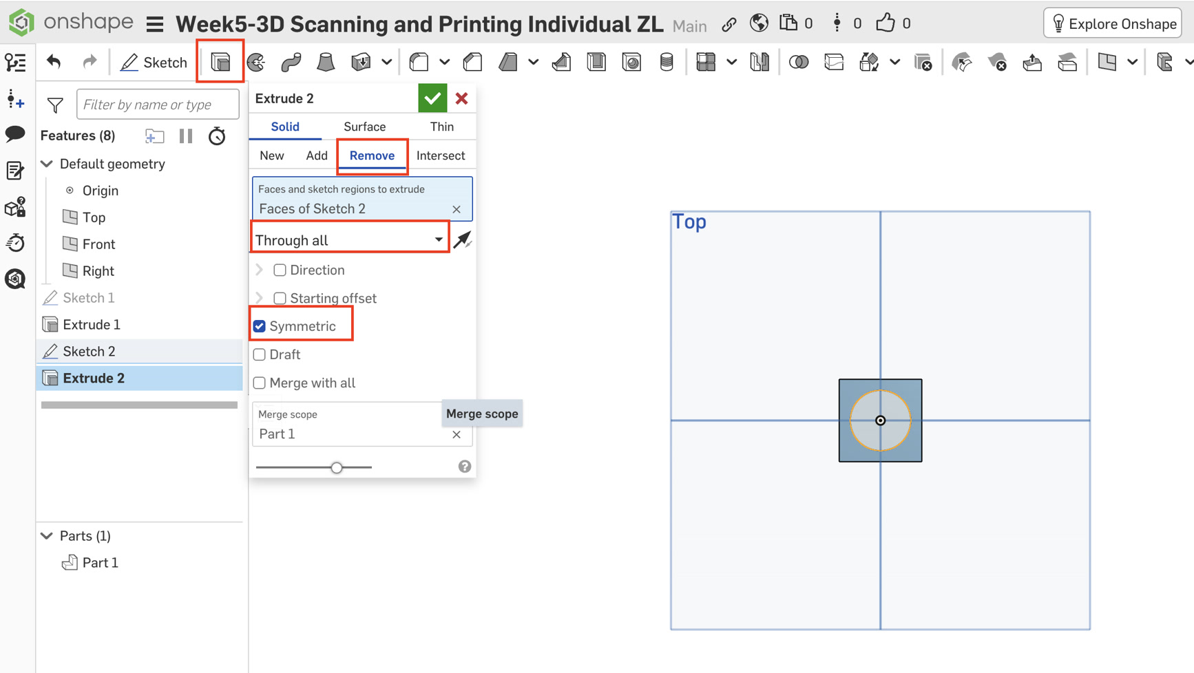
Repeat this process for the Top Plane and Right Plane. I now have a "hollow cage" with circular windows on all six sides.
Phase B: Modeling the Captive Ball
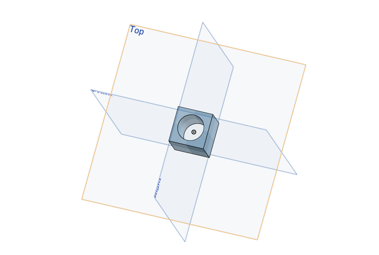
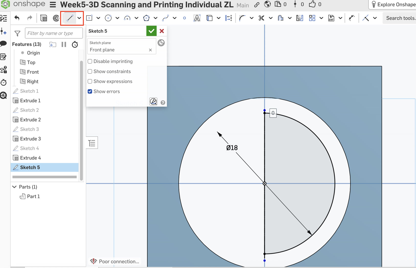
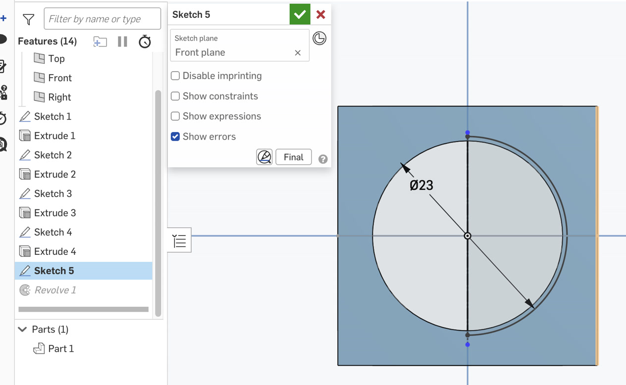
Sketching the Profile: Select the Front Plane and start a Sketch.
Construction Line: Select the Line tool and click the Construction icon. Draw a vertical line starting from the origin upwards. This is my rotation axis for further step of the ball.
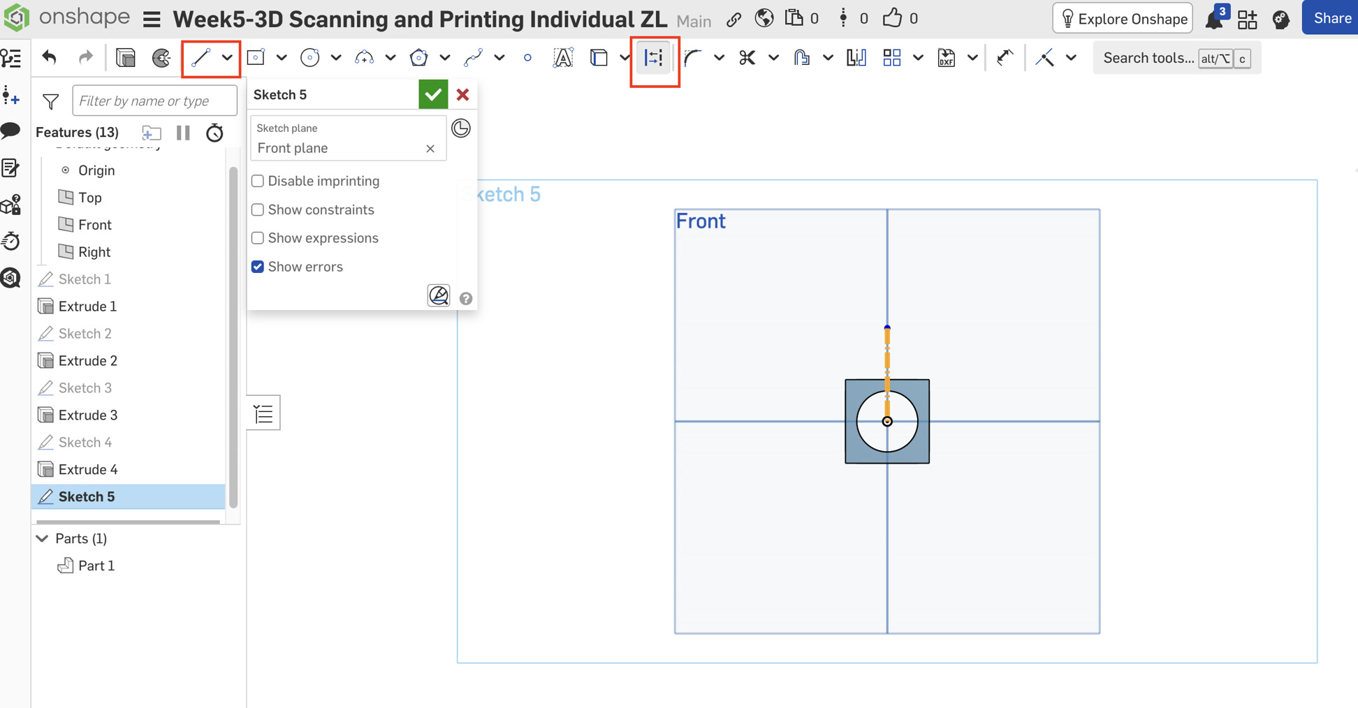
The Semicircle:
Draw a Center Point Circle at the origin with a 18mm diameter.
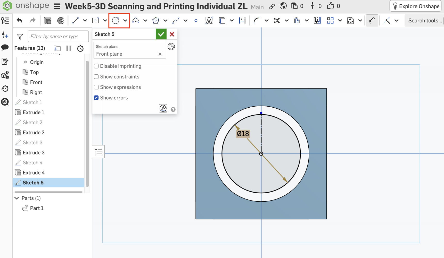
Use the Trim tool to cut the left half of the circle.
I encountered a problem when cutting half of the circle. The circle line looks grey and cannot be cutted for half piece.I checked the reason, it's because it is not a closed region. Then I used the Line tool (non-construction) to draw a solid vertical line connecting the top and bottom tips of the semicircle.
The half circle area is a closed area now, I can use the trim tool to cut the half circle on the left side.
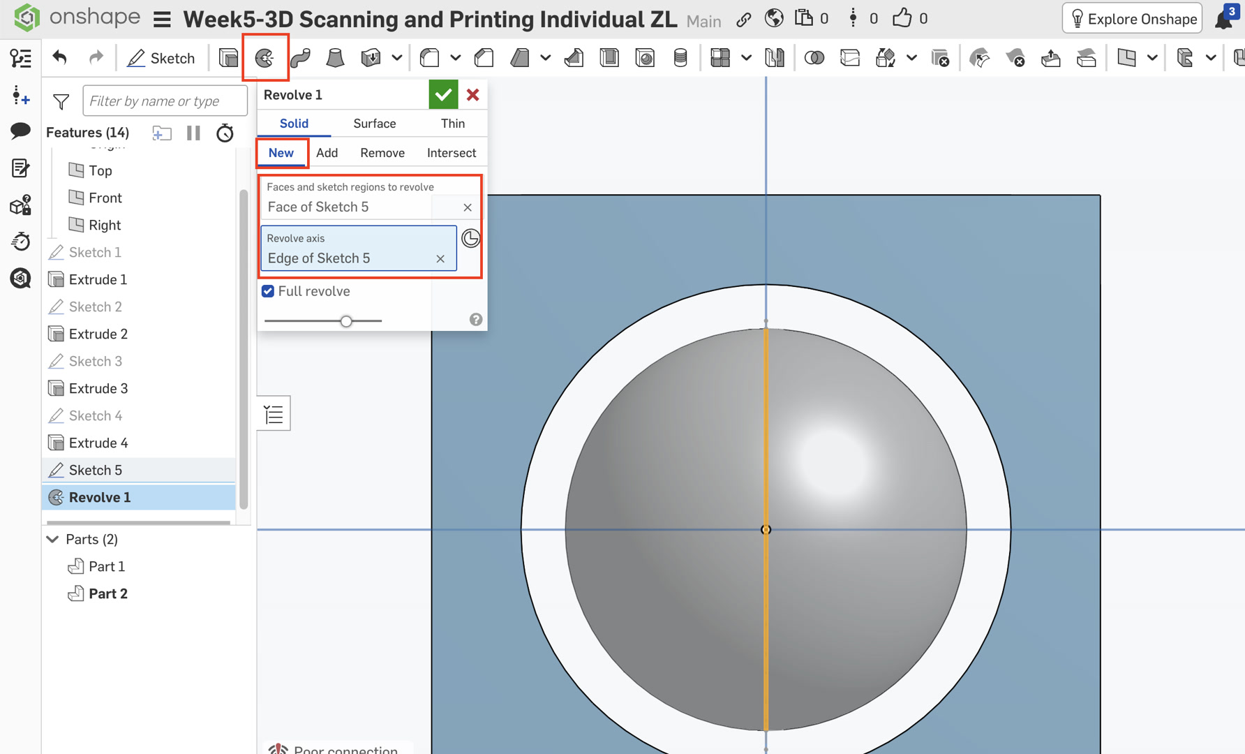
Revolving: Select the Revolve tool, click the semicircle. For Revolve axis, click the vertical line I just drew. In the Revolve menu, click "New". This ensures the ball is Part 2, separate from the cage (Part 1).
Phase C: Safety Checks
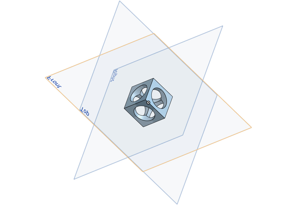
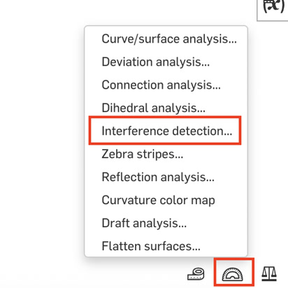
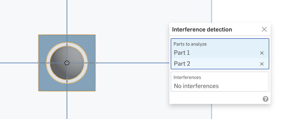
Interference Detection: Click the Display Analysis icon in the bottom-right panel and select Interference Detection. Select both the Ball and the Cage. It should say "No Interference."
Section View: Click the View Cube dropdown and select Section View. Click any plane to "cut" the model. This allows me to visually confirm a 2mm gap exists between the sphere and the cage walls.
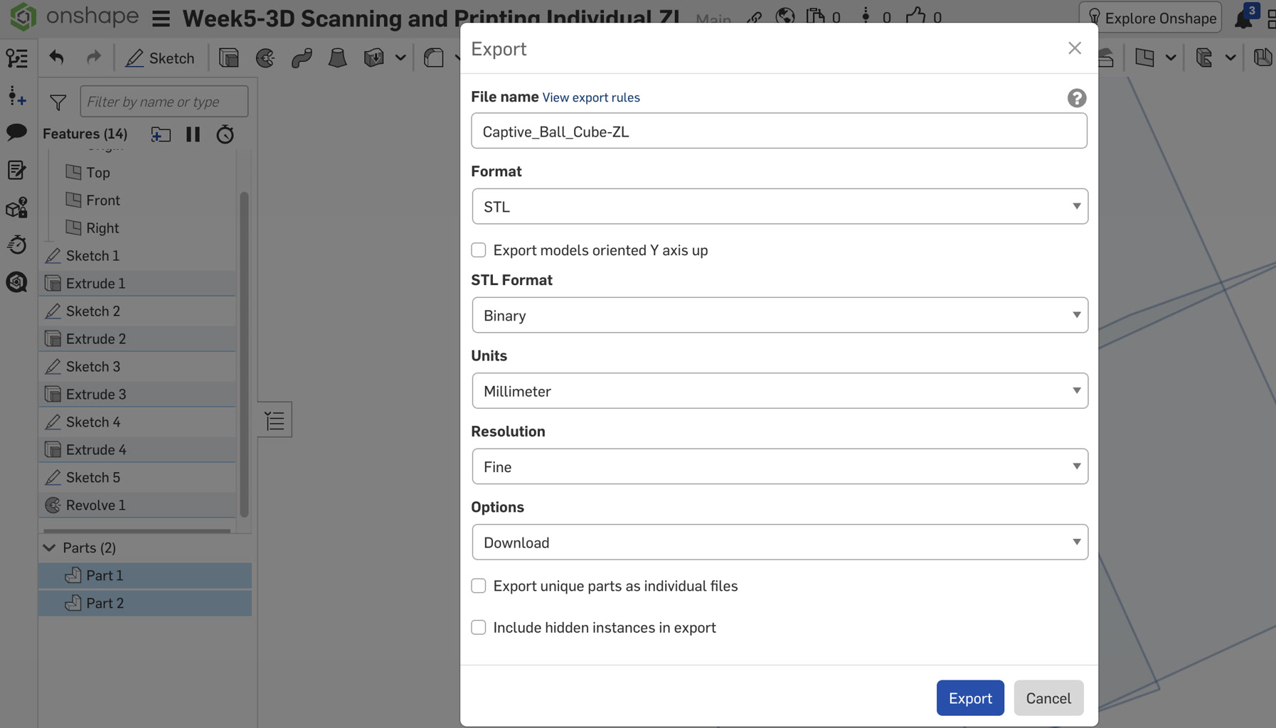
Exporting to STL file: Finally, I exported both Part 1 & 2 (Cube + Ball) to STL file, for further 3D printing.
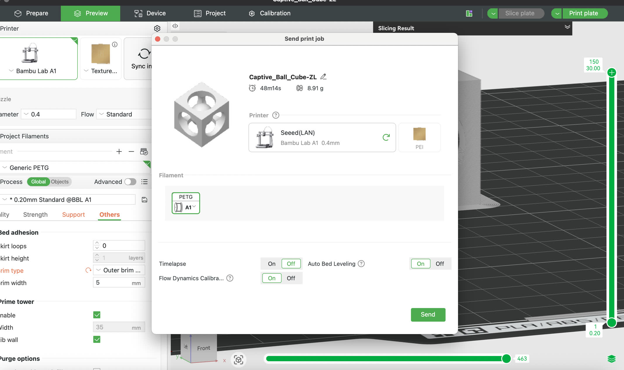
Slicing and Printing (Bambu Studio)
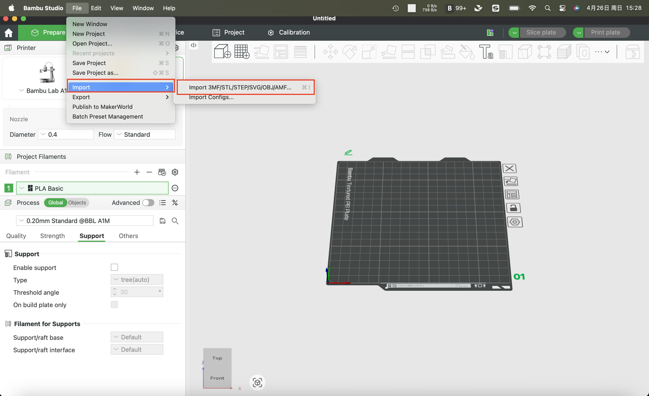
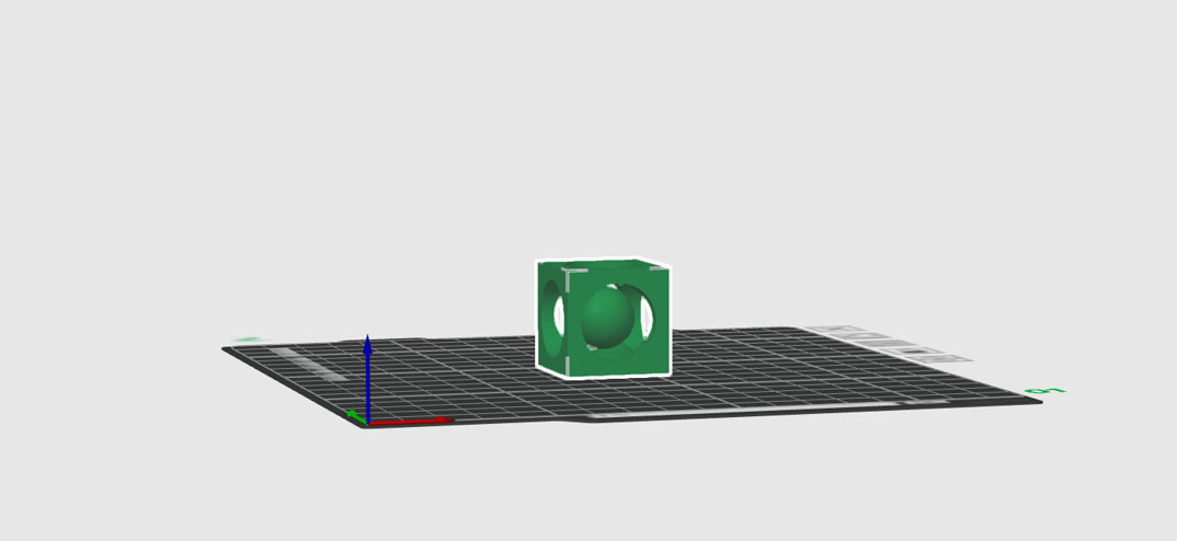
Import the STL file to Bambu StudioClick File--Import, and select the STL file just saved; then the model to be printed will be automatically placed on the work template.
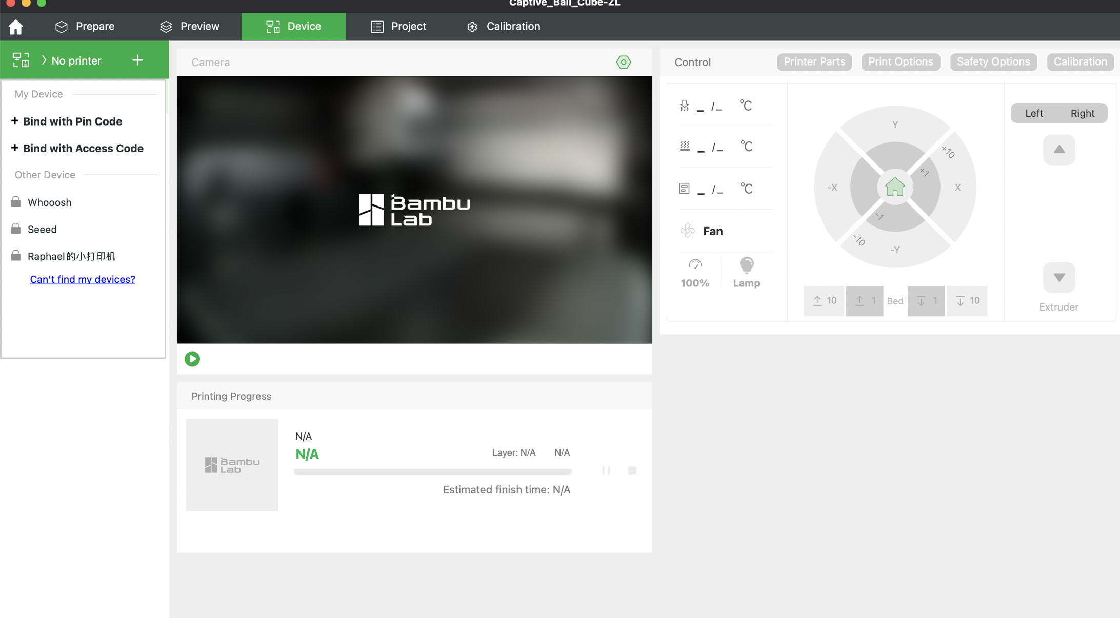
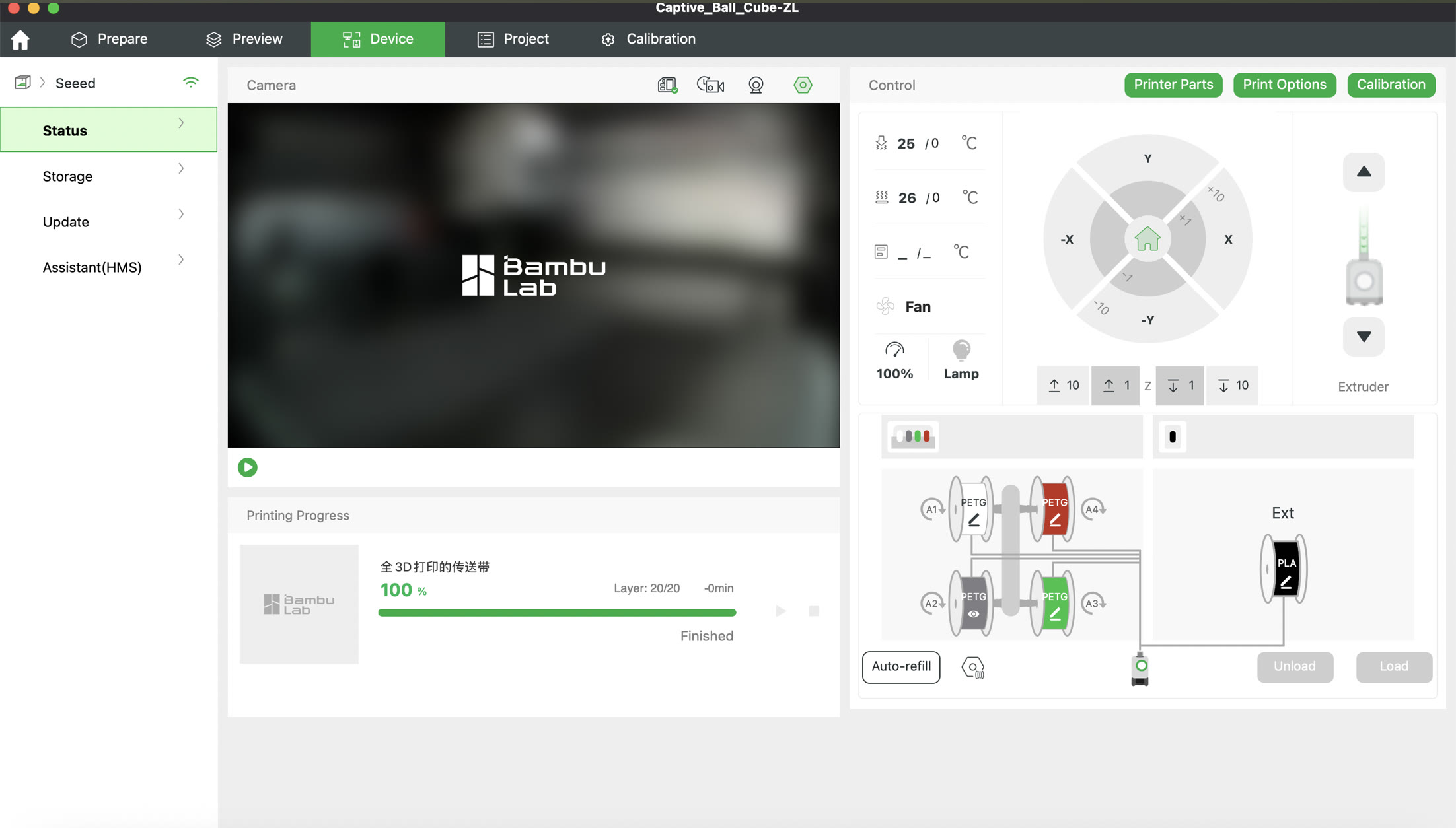
Connect to the same network as the Bambu 3D printer, choose Device on BambuStudio and selected the correct one, then I can see the settings of machine on BambuStudio and adjust settings as well.
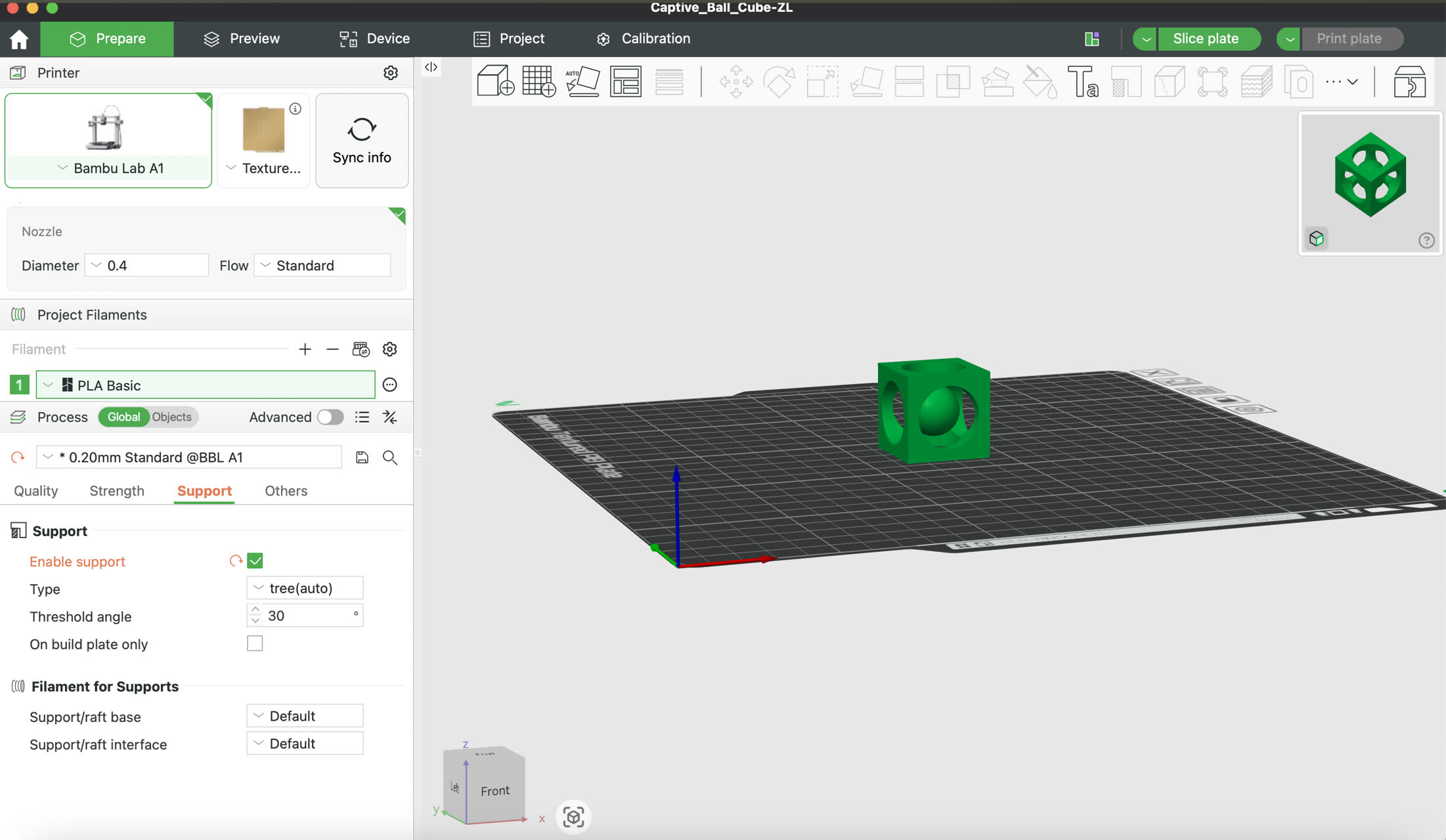
Setup: Ensure one flat face of the cage is flush against the build plate.
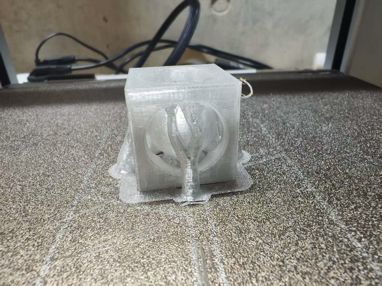
Support Strategy: As the ball inside is a floating object, it's better to use the tree support for printing. Select Enable support, and for Support Type, I chose Tree (Auto). Tree supports are easier to remove through small openings.
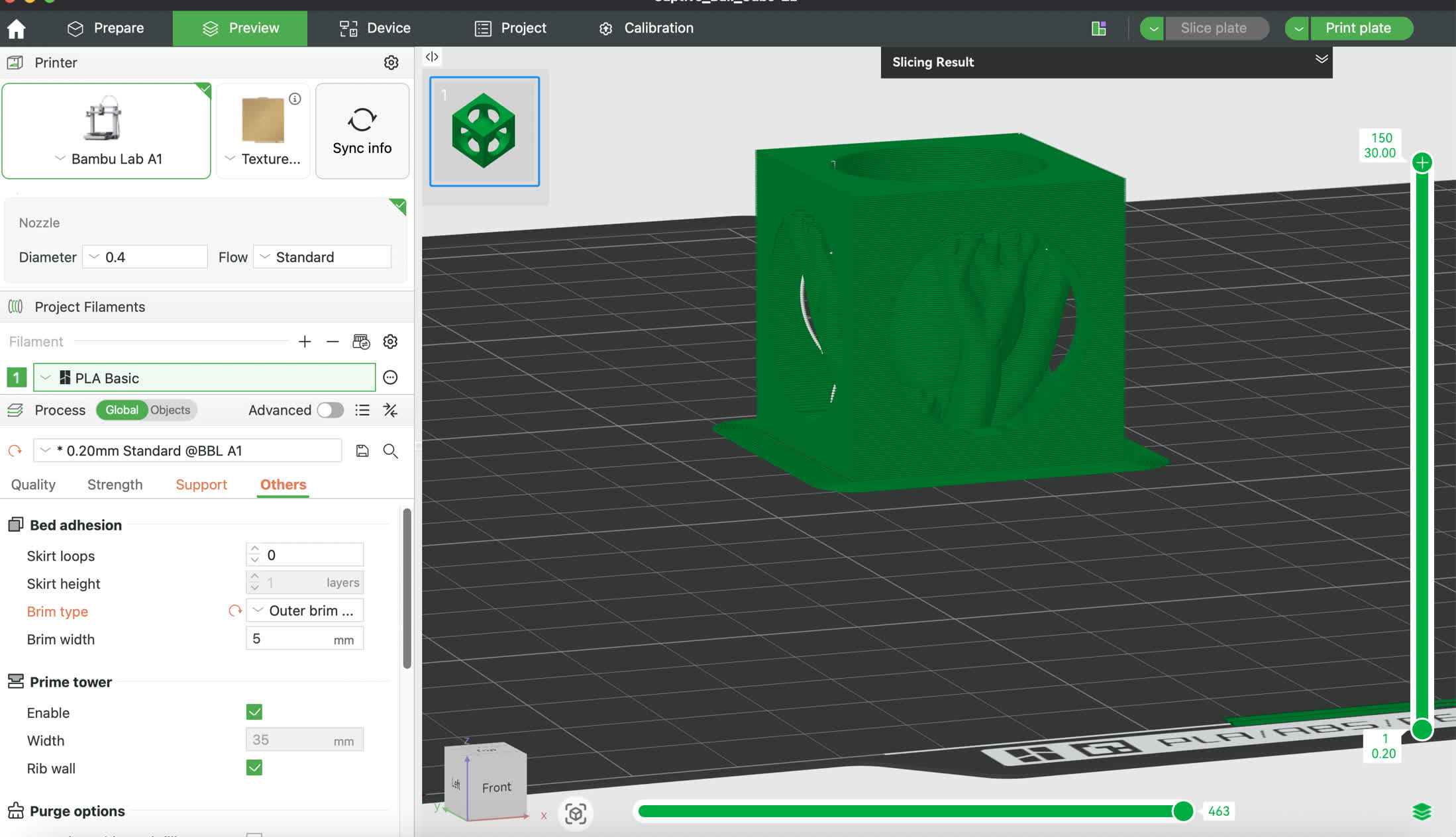
Rim type: I chose Outer brim as my classmate suggested, it built an outer “foundation" on the bottom, which protected the model from breaking when removing the 3D model from the plate.
I clicked "Slice plate" to see the what the tree support look like.
I changed the filament to the correct one I will use.
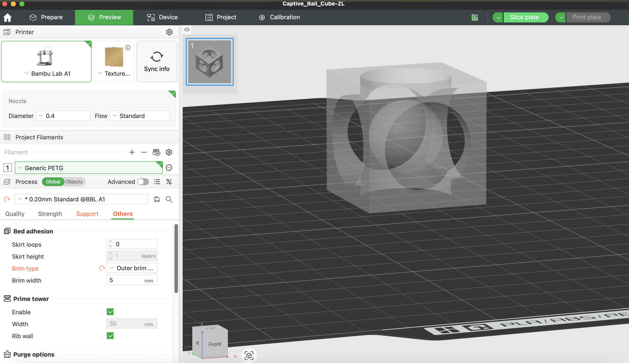
Click Pring plate, the Bamboo printer started to work to build this model.
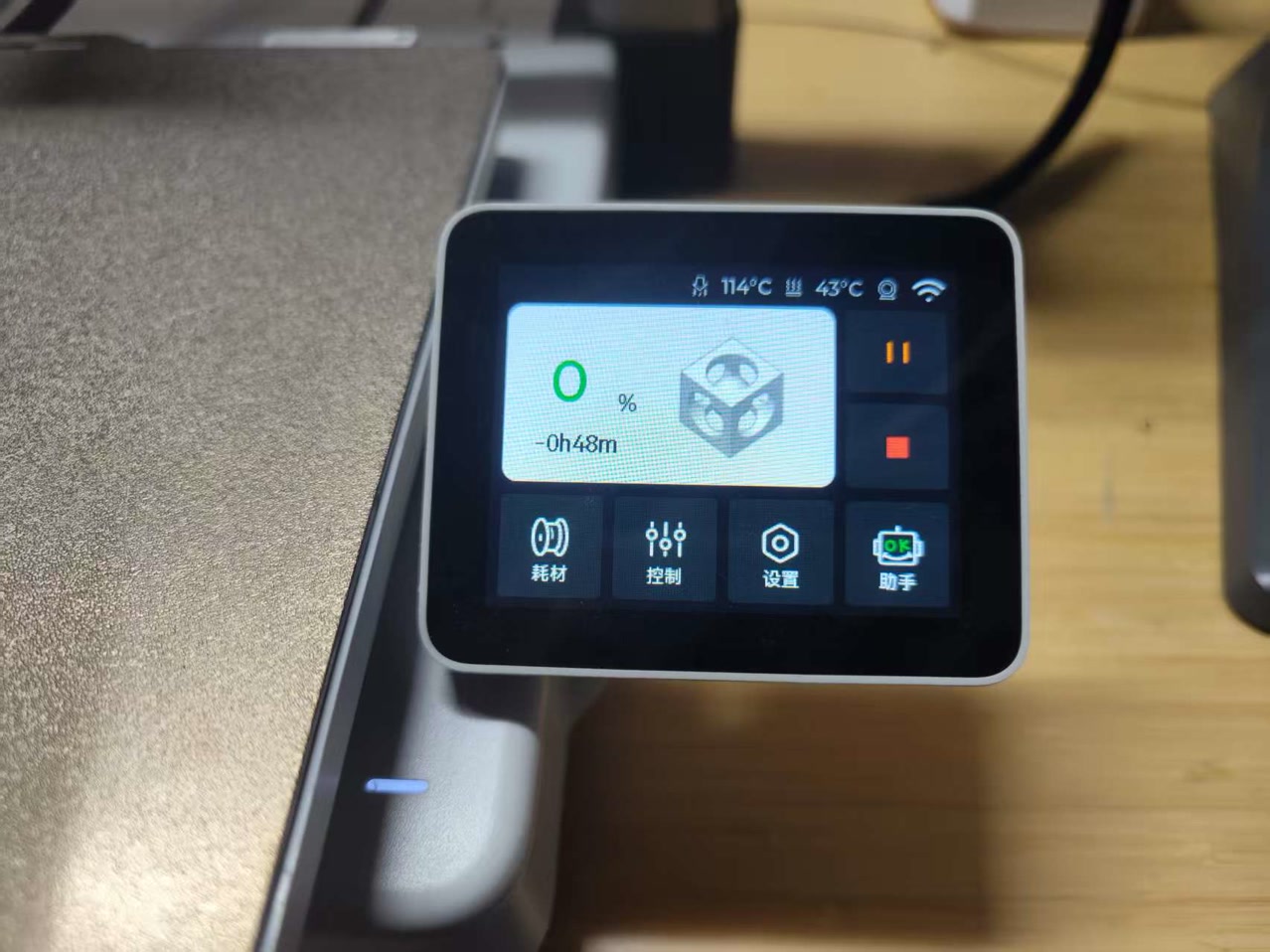
Printing process: 47%
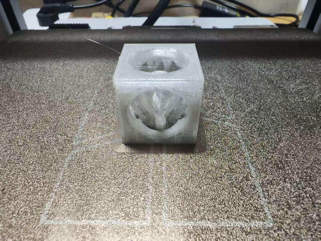
Final Result & Design Iteration
After printing finished, I got the first "Captive Ball in Cube" model.
I used the tool to remove the tree supports and some spagetti.
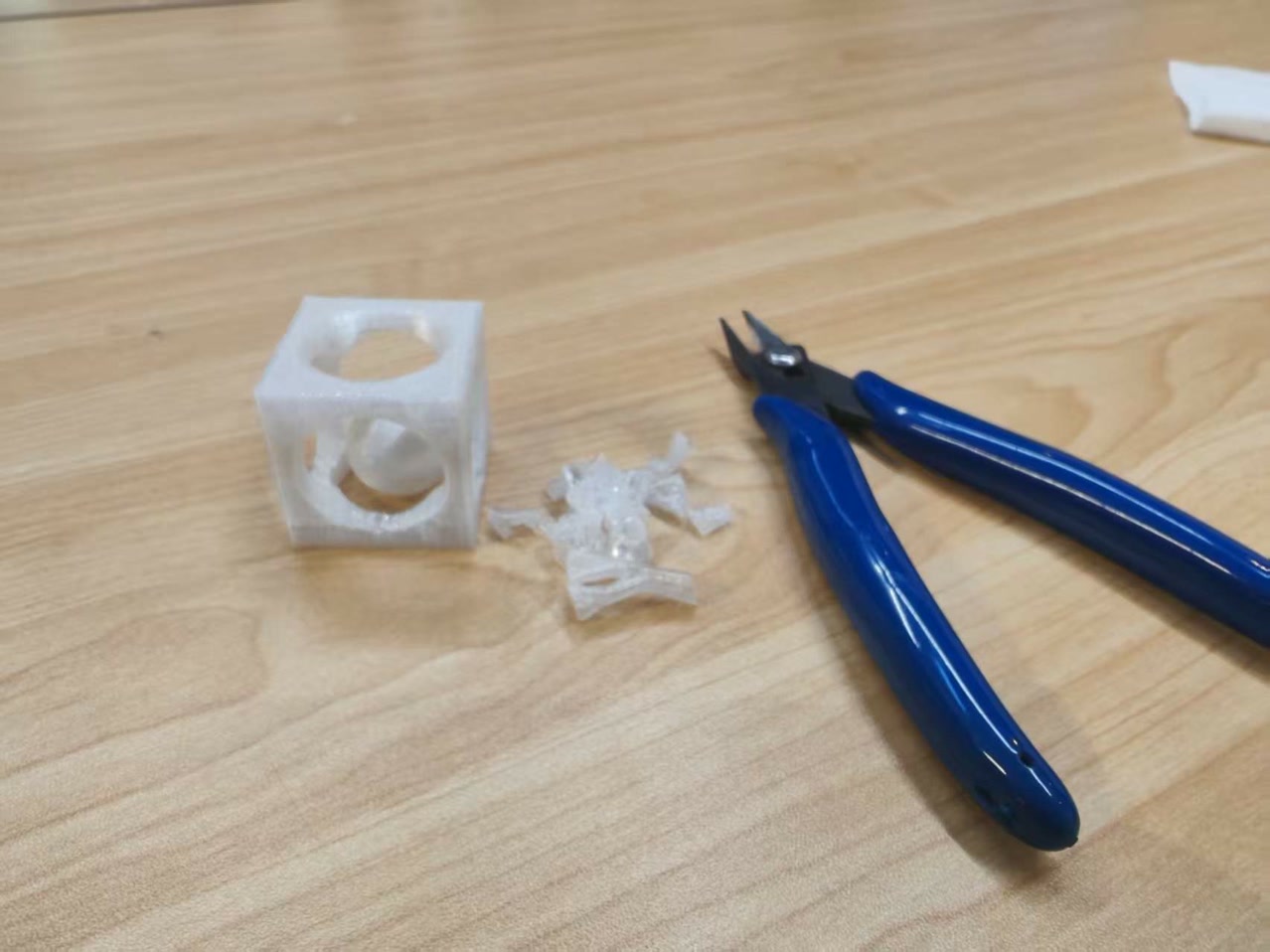
Problem: The ball is too small, it can be easily removed from the cube, I set the diameter of 18mm of the ball wrongly, 18mm<22mm (circle windows on the cube), it's a failure piece of work.
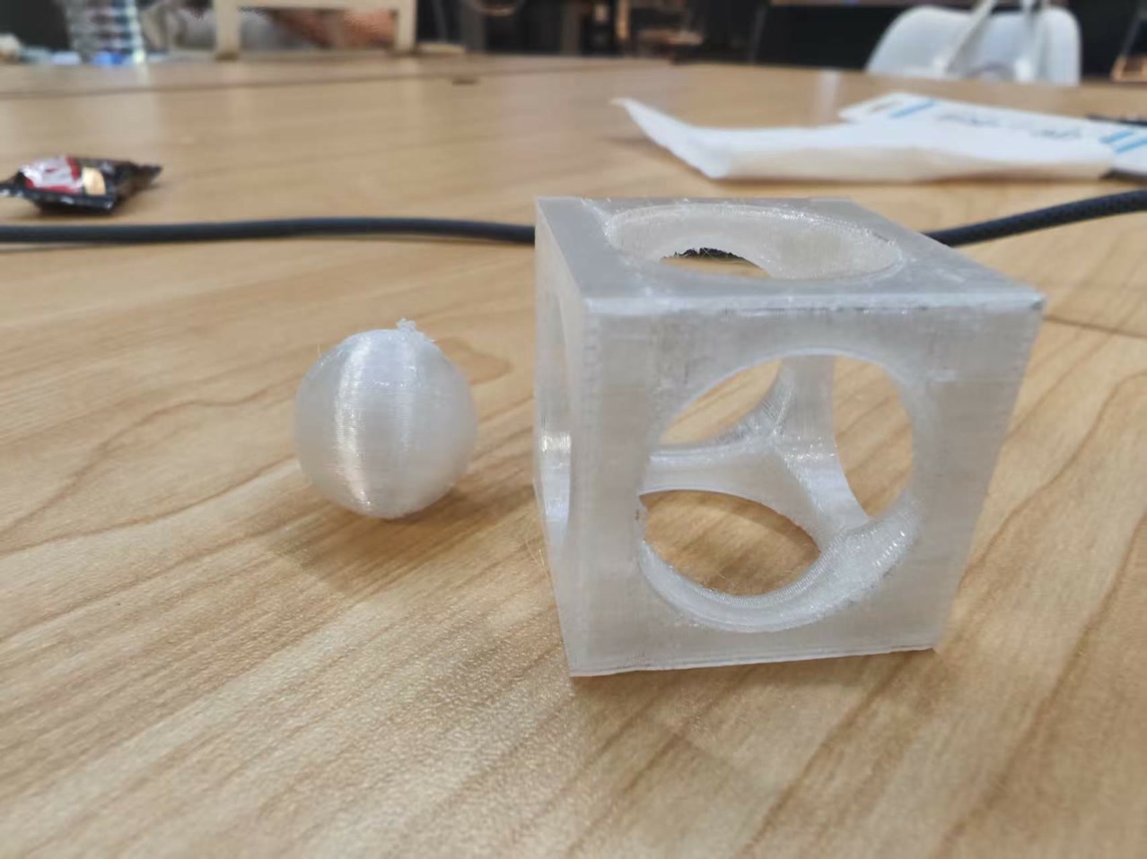
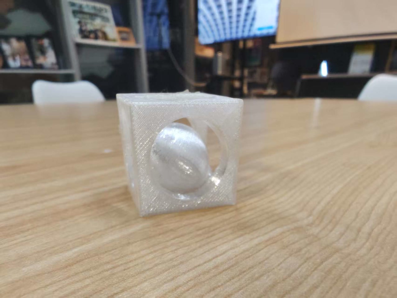
I changed the diameter of the ball from 18mm to 23mm (>22mm), and printed it again.
Second attempt: it's working this time!
STL file:
ball cage V1.2 ZL.stl2. 3D Scanning
Methodology: Video-to-3D
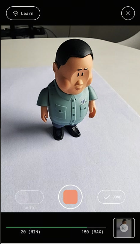
For the 3D scanning assignment, I used Photogrammetry via the Polycam app. Instead of taking individual photos, I utilized the Auto Video mode. This allows the app to automatically capture the most stable frames from a video stream, ensuring high overlap between images and a more consistent reconstruction of the geometry.
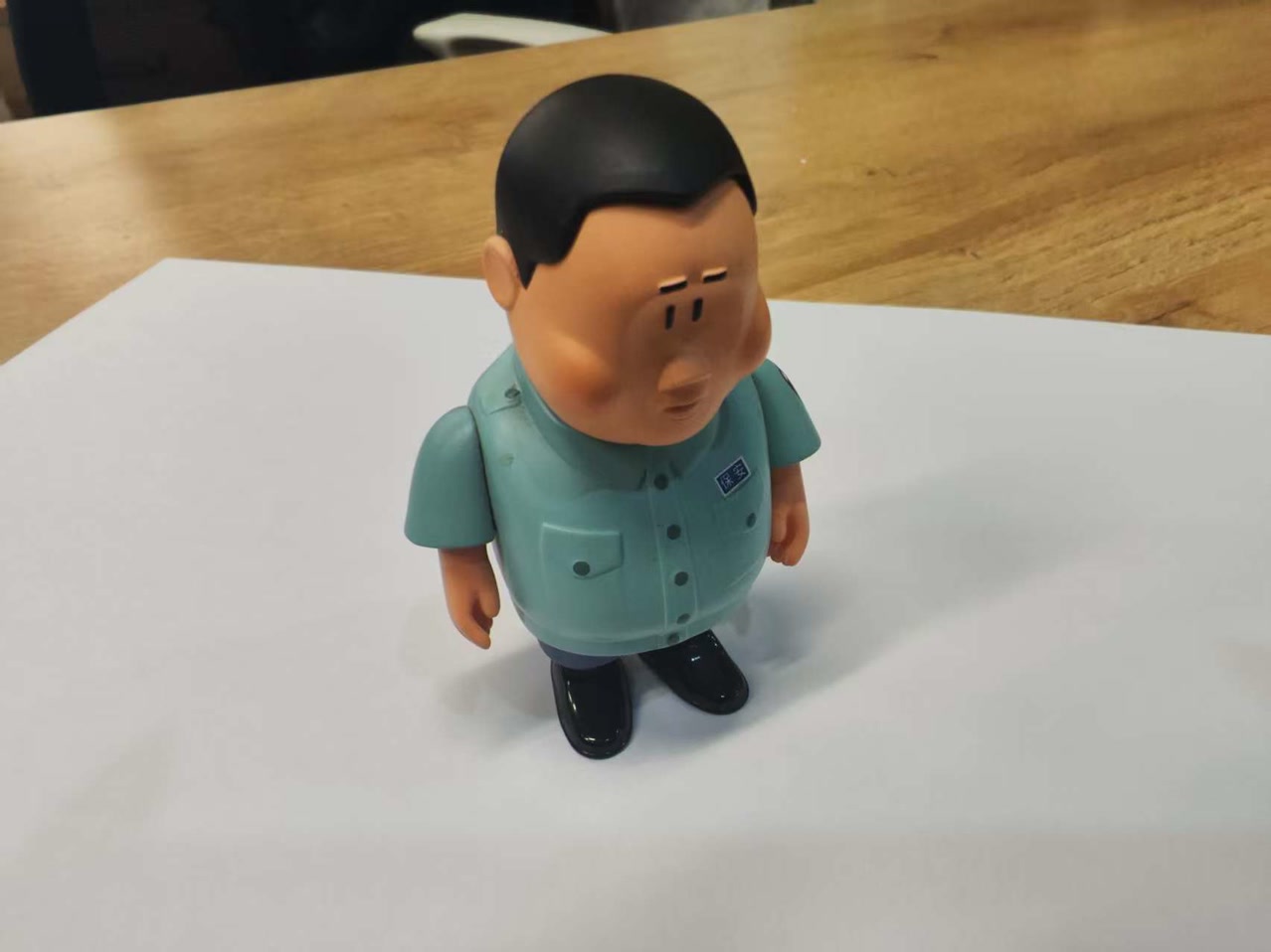
Target Object: Miniature Figurine
I chose a small figurine as my subject. Figures are excellent for scanning because they contain organic shapes and complex textures, though they can be challenging due to small crevices and thin parts.
The Scanning Process
-
Setting the Scene: I placed the figurine on a stable, non-reflective surface with consistent, ambient lighting to minimize harsh shadows. I place an A4 paper as bottom as well which can make the background more clear.
-
Capturing (Auto Video): I moved my phone in a slow, steady 360-degree orbit around the object. The app automatically extracted 60+ images from this video sequence.
-
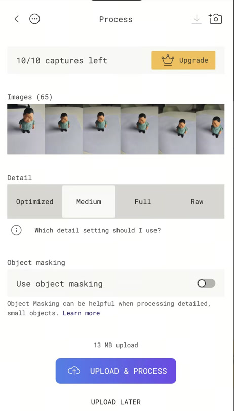
Processing: The images were uploaded to Polycam’s cloud server for processing. I selected the "Object" setting to optimize the mesh for a standalone item.
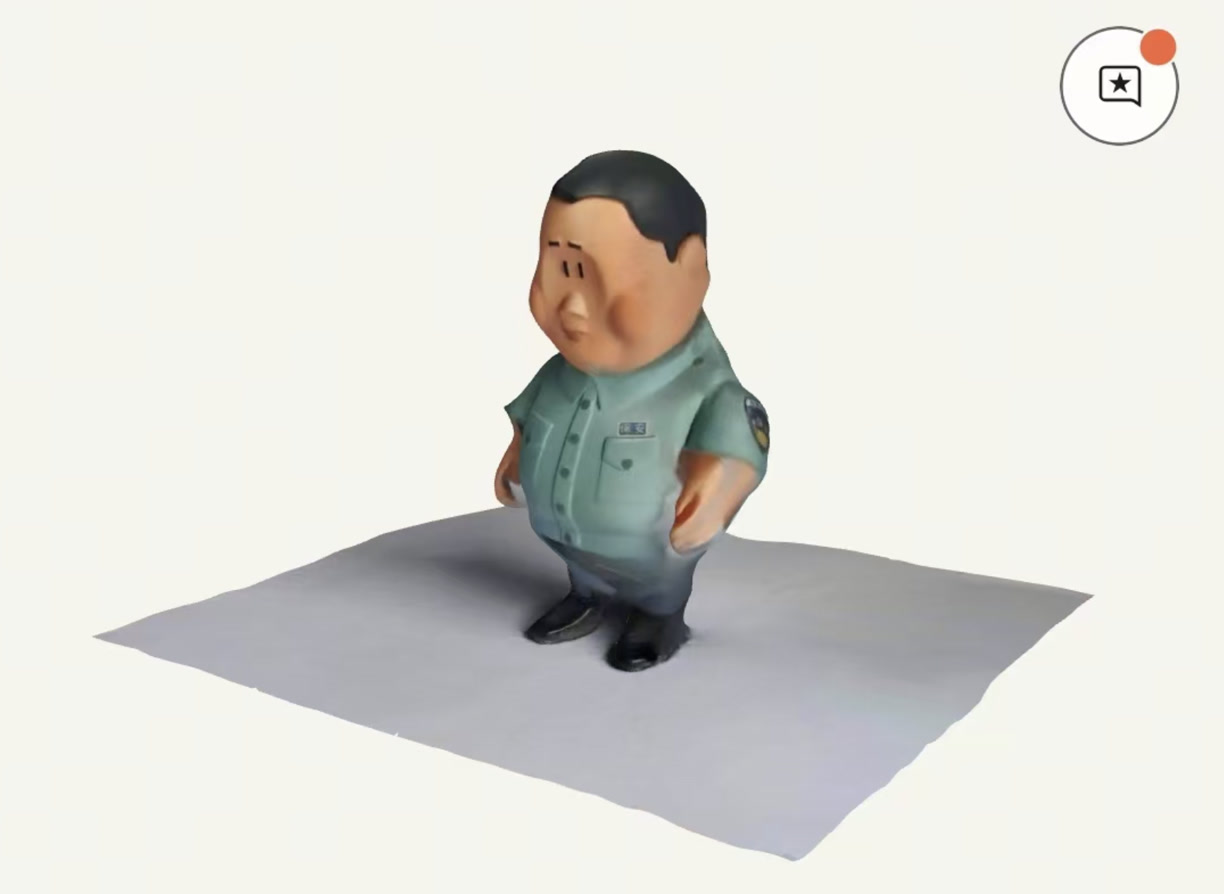
After processing, the APP jumped to 3D modeling visualization interface. Almost same as my original model, but some detailed part/narrow space is not clear enough. It might be caused by the not high solution photos, light intensity, or photo shooting angle etc.
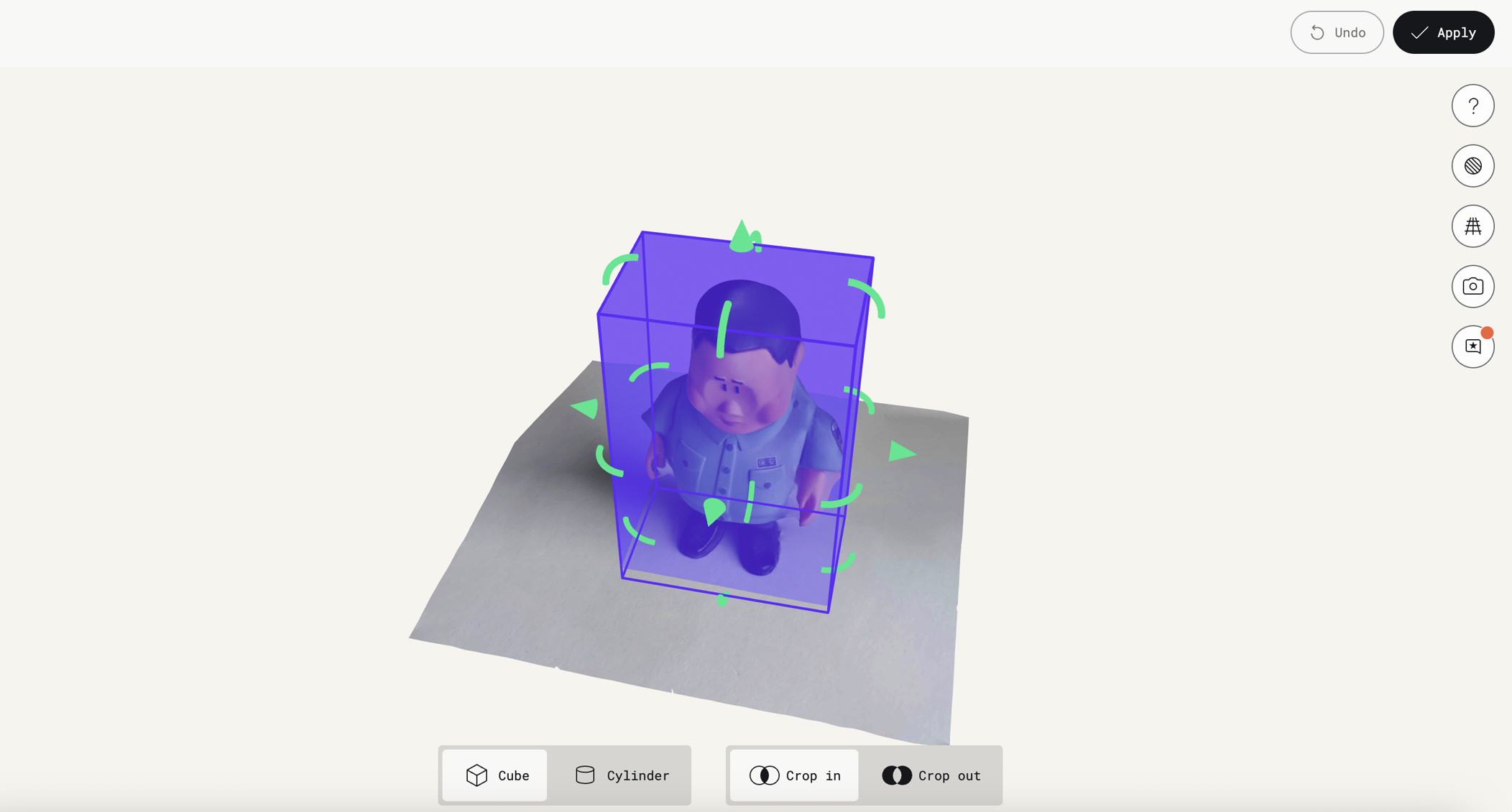
Post-Processing & Cleanup
Once the raw 3D model was generated, I opened the website of Polycam and logged in, used the Crop Tool to trim away the table surface and any background noise. I exported the scanned work to STL file.
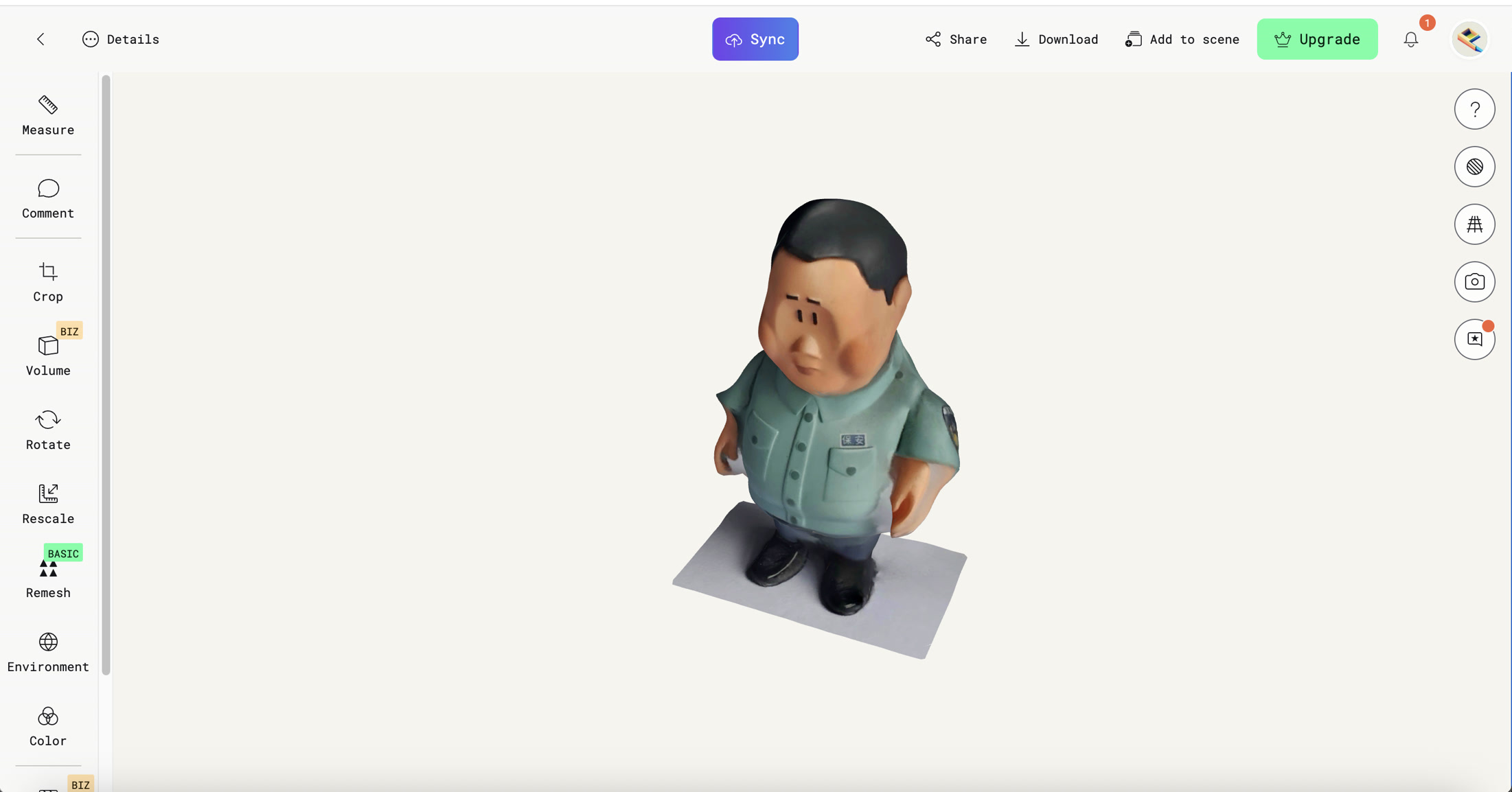
Evaluation
- Successes: The software successfully captured the overall silhouette and the vibrant color textures of the figurine.
- Challenges: Some of the deeper crevices under the arms appeared slightly "filled in" (the "webbing" effect), which is a common limitation of photogrammetry when the camera cannot see deep into narrow gaps.
- Conclusion: The result is a highly recognizable digital twin of the physical object, suitable for AR visualization or as a base for further digital sculpting.
Summary
Throughout the design, troubleshooting, and fabrication stages of this week, I have consolidated several key technical concepts and practical skills.
Additive vs. Subtractive: Additive manufacturing builds layer-by-layer, enabling complex internal geometries that traditional cutting (subtractive) cannot reach.
Parametric Design: Using dimensions and constraints in Onshape allows for quick iteration; changing one value automatically updates the entire model.
Closed Profile: A 2D sketch must be a "closed region" (shaded blue) with solid lines for tools like Revolve or Extrude to work.
Clearance & Tolerance: Maintaining a physical gap (e.g., 0.5mm - 2mm) between moving parts is essential to prevent them from fusing during printing.
Interference Detection: This digital check ensures parts do not overlap in 3D space before wasting time and material on a print.
Captive Geometry: Designing an internal part (23mm ball) larger than the outer openings (22mm) creates a permanent, non-assemblable interlocking structure.
Tree Support: A specialized 3D printing support structure that branches out to hold overhangs while being extremely easy to snap off.
Support Placement: Setting "Support on build plate only" prevents internal mess and ensures the cage walls remain clean.
Photogrammetry: The process of using a series of 2D photos (or video) to reconstruct a 3D digital model via software like Polycam.
STL Files: