Group Assignment: Microcontroller Characterization
1. Objective
The goal of this group assignment is to research and compare the architectures, performance, and development workflows (toolchains) of mainstream microcontrollers, specifically focusing on the RP2040 and ESP32-C3 within the Seeed Studio XIAO ecosystem.
2. Microcontroller Landscape
Before a deep dive into specific chips, we analyzed the three pillars of current hobbyist and industrial MCU architectures:
- 8-bit AVR (Legacy & Robustness): High tolerance for voltage fluctuations, easy to hand-solder, but limited by clock speed and memory.
- ARM Cortex-M (Industry Standard): Dominates the 32-bit market. High efficiency with a massive ecosystem (STM32, RP2040).
- RISC-V (Open Standard): A rising architecture that is royalty-free and highly customizable. It is increasingly used in modern IoT chips like the ESP32-C3.
3. Technical Characterization: RP2040 vs. ESP32-C3
Click the image to view the sheet. RP2040: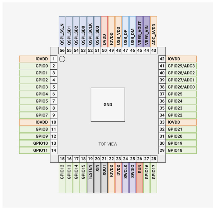
(Source: pip-assets.raspberrypi.com)
ESP32C3: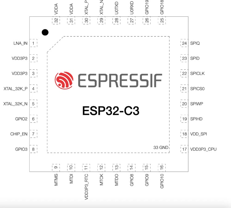
(Source: ESP32C3 Dev Module Development Board Pinout and Technical Specifications)
4. Development Toolchains & Workflow
We compared how code moves from our computers to the silicon. The "Toolchain" is the set of tools (compiler, linker, uploader) that makes this happen.
Click the image to view the sheet.Observation: The RP2040 is easier for beginners because it can appear as a USB drive (UF2 bootloader). The ESP32-C3 requires a more traditional serial-over-USB approach but offers far superior debugging logs via the serial monitor.
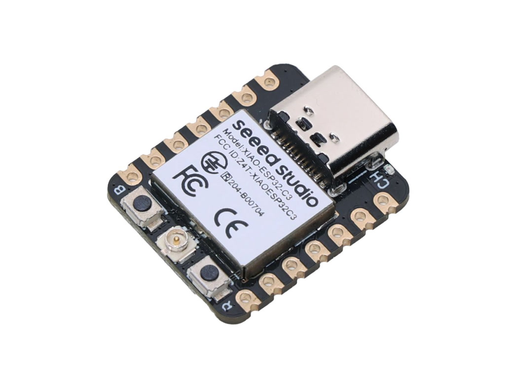
I picked the XIAO ESP32-C3
For my individual project, I chose the XIAO ESP32-C3 as my primary board.
My reasoning is simple: I am interested in building "connected" devices that can send data or notifications in potential future projects. While the RP2040 is a great computer for learning basic logic, it lacks built-in networking. The ESP32-C3, on the other hand, is a compact IoT computer that can transmit data wirelessly via Wi-Fi and Bluetooth.
Individual Assignment:
1. From Zero to One - My Understanding of Embedded Programming
Coming from a non-engineering background, the term "Embedded Programming" initially felt like a black box. To demystify it, I approached this week’s assignment by breaking it down into three logical layers: the Brain (Hardware), the Language (Code), and the Manual (Datasheet).
1.1 Conceptualizing the "Brain": What is an MCU?
Before exploring specific hardware, I needed to establish a clear understanding of what a Microcontroller Unit (MCU) actually is and how it differs from the computing systems I interact with daily. As someone new to embedded systems, I found it helpful to move from the familiar logic of a PC to the specialized logic of these smaller chips.
A. The Shift in Perspective: General Computing vs. Embedded Systems
In my professional life, I primarily use a "General-Purpose Computer" (a laptop or smartphone). These systems are designed for versatility—they have a central processor (CPU) that coordinates with separate components for memory (RAM) and storage (Hard Drive) to handle a massive range of tasks.
An MCU, however, represents a different philosophy. It is an "Embedded System," meaning all the essential components—the processor, memory, and input/output interfaces—are integrated into a single, tiny chip. It isn't designed to run an operating system like Windows; it is built to execute a single, dedicated program reliably. It prioritizes low power consumption and direct interaction with physical hardware over raw processing power.
B. The Core Components of MCU Logic
To move beyond seeing the chip as a "black box," I broke down its internal architecture into three functional layers:
- The Processor Core & Architecture: This is the engine that executes instructions. I learned that every MCU is built on a specific Architecture (such as RISC-V or ARM). This architecture is essentially the logic blueprint that defines how the processor communicates with the rest of the chip. It’s the "instruction set" that determines how efficiently the chip can handle tasks.
- Memory Hierarchies (Flash vs. SRAM): Understanding how an MCU remembers information was a key turning point for me. There are two distinct types of memory at play:
- Flash Memory: This is non-volatile storage. This is where the code I write is permanently stored. Even when the power is disconnected, the program remains intact.
- SRAM (Static RAM): This is the volatile working memory. The MCU uses this space to store temporary data while the program is running. Once the power is cut, this data is lost.
- Peripherals and I/O: The real utility of an MCU lies in its ability to interact with the physical world through pins. These pins are the interface between the digital logic inside the chip and the analog reality outside.
- Inputs: These allow the MCU to read signals, such as the state of a button or the data from a sensor.
- Outputs: These allow the MCU to control other components, such as triggering an LED or sending a signal to a motor.
C. The Translation: Analog vs. Digital
One of the most important concepts I encountered was the distinction between analog and digital signals. In the real world, most data is Analog—it exists as a continuous range (like the gradual change in temperature or light). However, the MCU operates in a Digital world of 0s and 1s.
To bridge this gap, MCUs use an ADC (Analog-to-Digital Converter). This component samples the continuous analog signal and converts it into a digital value that the processor can actually calculate. Understanding this "translation" process is fundamental because it governs how the chip perceives environmental data.
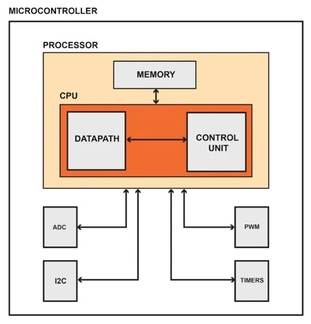
For example, from this picture, I interpreted the internal workflow of the MCU as follows:
- The Processor (CPU): The central manager that executes instructions and coordinates all activities.
- The Memory (Flash & RAM): Flash acts as the permanent storage for my program (the instruction manual), while RAM serves as the temporary workspace for the CPU to store variables during operation.
- The Data Bus: This is the internal "highway" that facilitates the rapid movement of data between the CPU, memory, and peripherals.
- Peripherals (Specialized Departments):
- I2C / Serial Interfaces: The communication hub for exchanging data with external hardware.
- ADC (Analog-to-Digital Converter): The translator that converts continuous real-world signals into digital data for the CPU.
- Timers & PWM: The precision controllers that manage timing and output frequency for accurate hardware manipulation.
1.2 Decoding the "Manual": The Power of a Datasheet
After understanding the general framework of an MCU, I looked into the specific capabilities of the XIAO ESP32C3 by reviewing its datasheet. This allowed me to see how the theoretical concepts apply to actual hardware.
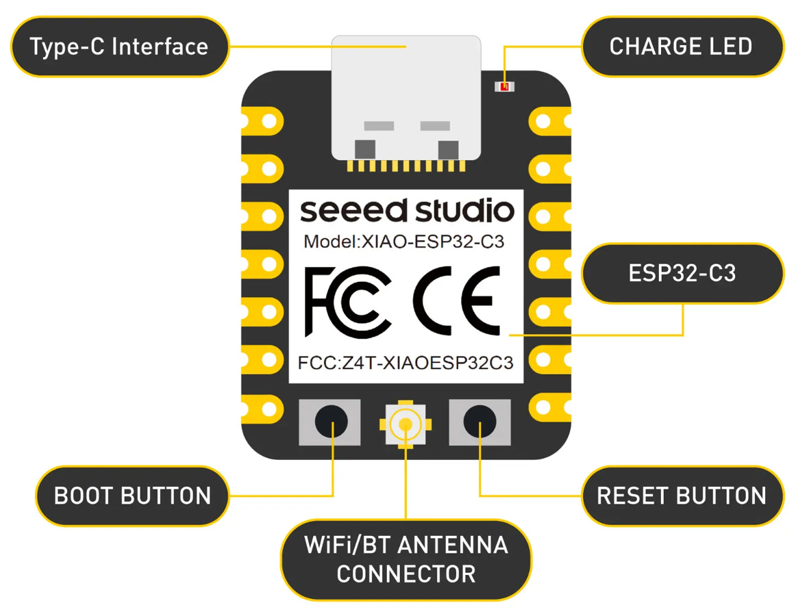
- Architecture (RISC-V): The chip is based on the 32-bit RISC-V instruction set. Unlike traditional proprietary architectures, RISC-V is open-source and designed for high efficiency, serving as the logical foundation for how the processor handles commands.
- Memory Configuration:
- SRAM (400 KB): This is the volatile memory used for temporary data processing while the program is running.
- Flash (4 MB): This is the non-volatile storage where the code is permanently saved. Even without power, the program remains intact here.
- Peripherals (Interfaces): The datasheet highlights how the chip interacts with external components:
- ADC (Analog-to-Digital Converter): This converts continuous analog signals from the real world (like light levels or voltage) into digital values that the MCU can process.
- GPIO Pins: These are general-purpose pins that I can configure as Inputs (to read sensors or buttons) or Outputs (to control LEDs or actuators).
- Communication Protocols: Despite its small size, the board supports both wired protocols (UART, I2C, and SPI) and wireless connectivity (Wi-Fi and Bluetooth 5.0). This makes it a versatile tool for IoT applications.
2. Simulation Workflow: Wokwi simulation with XIAO ESP32-C3
To bridge the gap between design and physical hardware, I am using Wokwi for my initial programming phase. Wokwi is a browser-based simulator for embedded systems that allows me to wire components and test code in a risk-free environment.
What is Wokwi?
Wokwi is a powerful online tool that emulates microcontrollers like the XIAO ESP32C3 and Arduino. It provides a virtual breadboard where I can drag and drop LEDs, sensors, and displays, connecting them to the MCU just as I would in real life. It even simulates the wireless capabilities of the chip, such as Wi-Fi scanning.
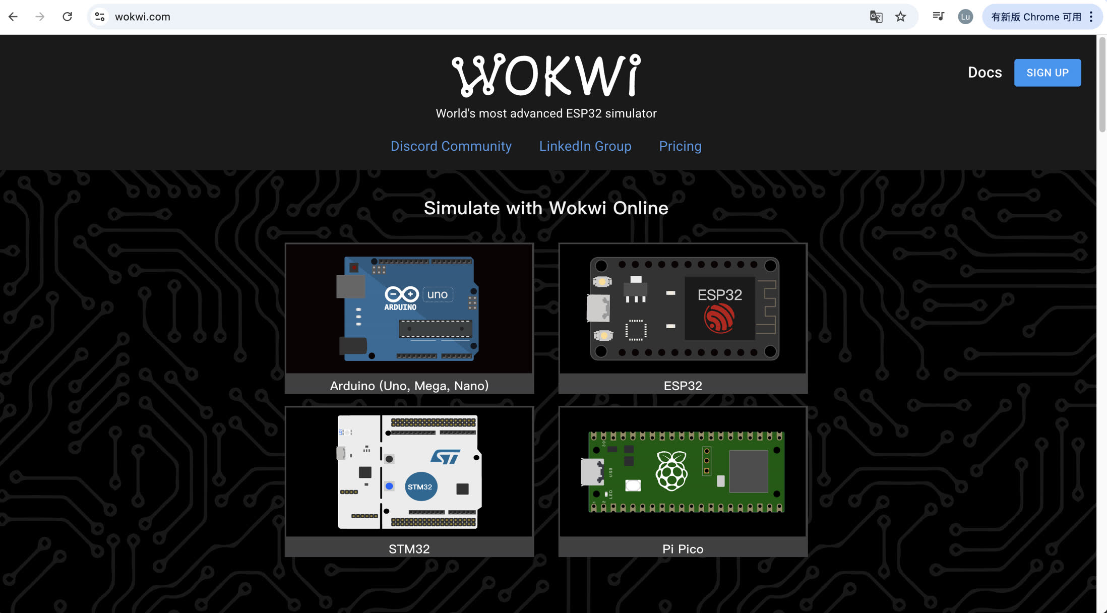
First, I went to website https://wokwi.com/, and sign up.
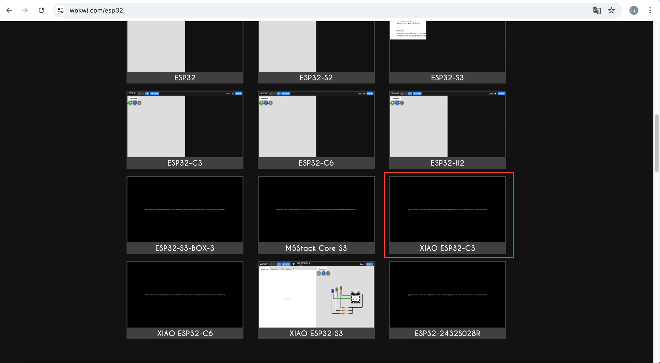
Then choose ESP32 and select XIAO ESP32C3 to do the simulation.
The default template already contains the XIAO ESP32C3 with red, blue, green LED connection.
I removed everything and started to create my first simulation.
Example1 - Blinking LED
I clicked "+" and added a red LED.
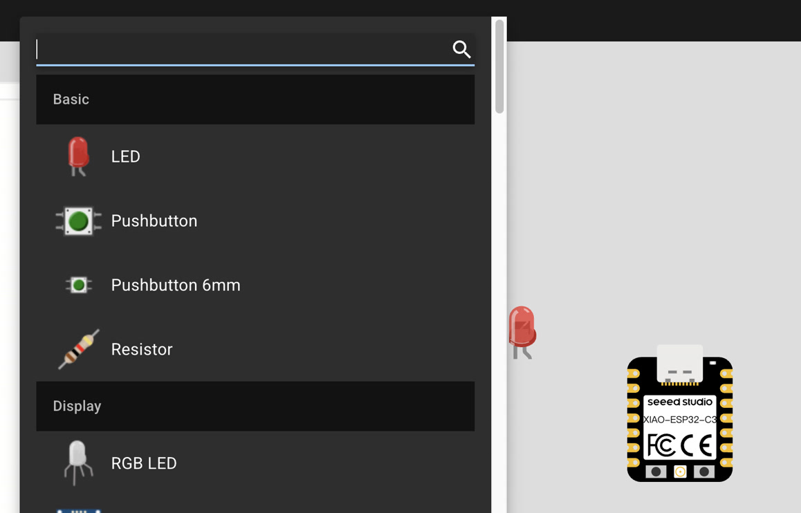
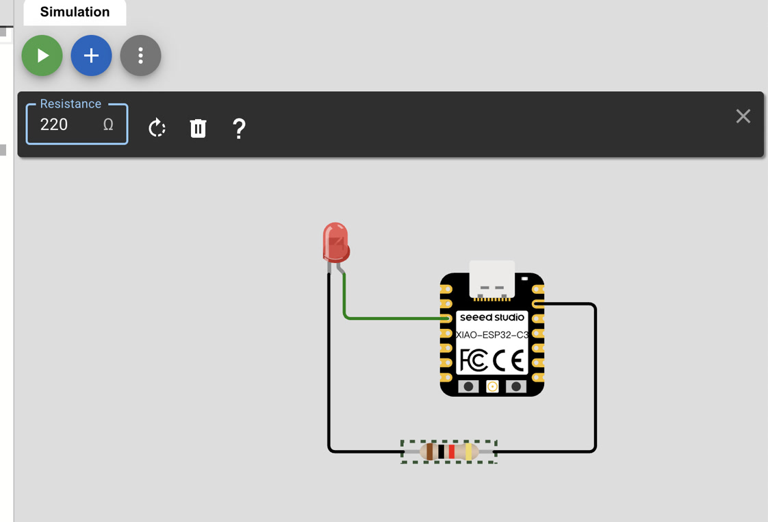
Then I wired the LED to XIAO ESP32C3, the positive pole to D2, and the negative pole to GND. Then added a resistor of 220Ω to the GND wire.
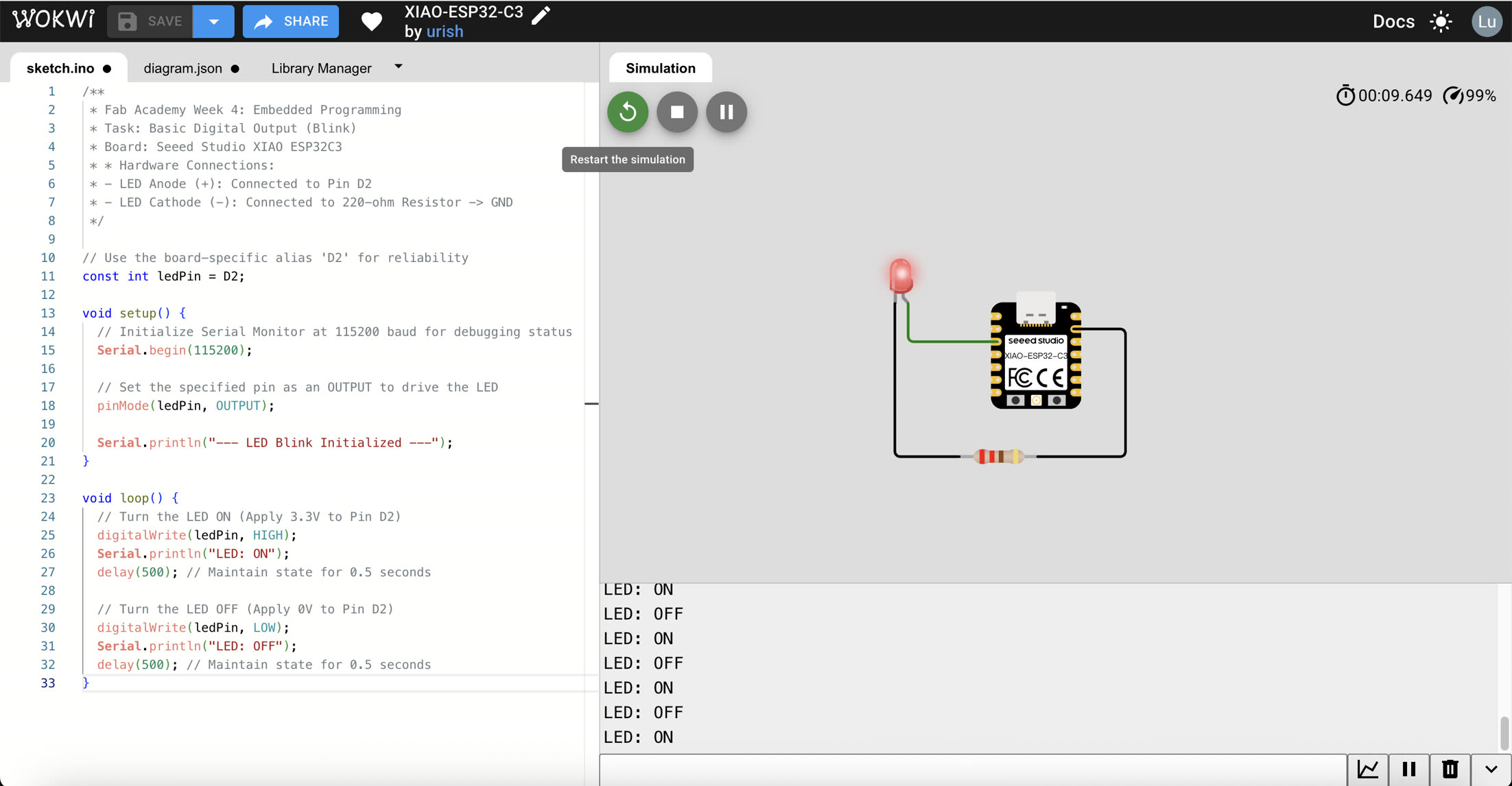
Then I got the code from Google Gemini, and paste it to the code area "sketch.ino":
/**
 * Fab Academy Week 4: Embedded Programming
 * Task: Basic Digital Output (Blink)
 * Board: Seeed Studio XIAO ESP32C3
 * * Hardware Connections:
 * - LED Anode (+): Connected to Pin D2
 * - LED Cathode (-): Connected to 220-ohm Resistor -> GND
 */

// Use the board-specific alias 'D2' for reliability
const int ledPin = D2;

void setup() {
  // Initialize Serial Monitor at 115200 baud for debugging status
  Serial.begin(115200);

  // Set the specified pin as an OUTPUT to drive the LED
  pinMode(ledPin, OUTPUT);

  Serial.println("--- LED Blink Initialized ---");
}

void loop() {
  // Turn the LED ON (Apply 3.3V to Pin D2)
  digitalWrite(ledPin, HIGH);
  Serial.println("LED: ON");
  delay(500); // Maintain state for 0.5 seconds

  // Turn the LED OFF (Apply 0V to Pin D2)
  digitalWrite(ledPin, LOW);
  Serial.println("LED: OFF");
  delay(500); // Maintain state for 0.5 seconds
}
Then I ran the program and the red LED was blinking. It turned on for 0.5 second and turned off for 0.5 second so it seems blinking.
XIAO-ESP32-C3 LED blink - Wokwi ESP32, STM32, Arduino Simulator
Example 2 - OLED
Before connecting the OLED display, I studied different communication protocols.
- Communication Protocols Communication protocols are the shared "languages" that chips use to talk to each other.
Serial: Data is sent one bit at a time (like a single-lane road).
Synchronous: Uses a "Clock" signal to sync timing between devices.
Asynchronous: No clock signal; devices must agree on a set speed (Baud rate) in advance.
- Main Communication Types
- UART (Universal Asynchronous Receiver-Transmitter) Wiring: 2 wires (TX/RX).
Method: Asynchronous. Both sides must set the same Baud rate (e.g., 115200).
Use: Debugging via Serial Monitor or connecting GPS modules.
- I2C (Inter-Integrated Circuit) —— Used by OLED Wiring: 2 wires (SDA for data, SCL for clock).
Method: Synchronous. Uses unique addresses to support multiple devices on the same two wires.
Use: Short-distance sensors and OLED displays.
- SPI (Serial Peripheral Interface) Wiring: Usually 4 wires (MOSI, MISO, SCK, CS).
Method: Synchronous. Extremely fast but uses more pins.
Use: SD cards and high-resolution screens.
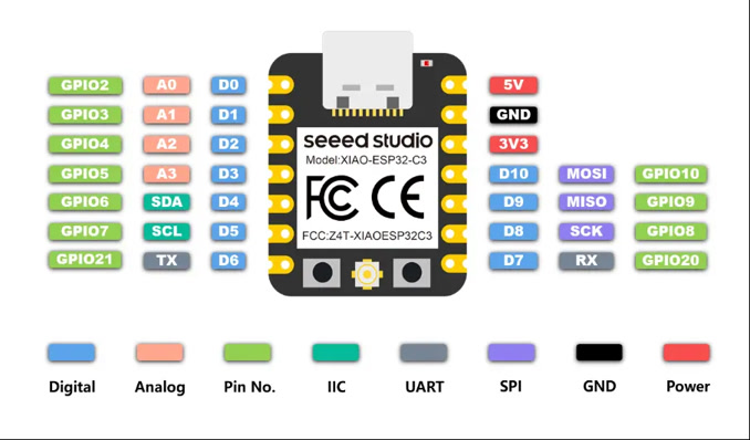
- XIAO ESP32C3 Supported Ports
- Physical Abstraction: A single physical pin on the XIAO ESP32C3 can perform multiple roles. This is known as Pin Multiplexing.
- GPIO as the Base: GPIO (General Purpose Input/Output) is the fundamental identity of the digital pins.
- Specialized Protocols: Roles like IIC (SDA/SCL), UART (TX/RX), and SPI are specialized functions assigned to specific GPIOs via software.
- The Constraint: While a pin is versatile, it can only serve one function at a time. For example, if a pin is being used for I2C communication with an OLED, it cannot simultaneously act as a simple toggle switch for an LED.
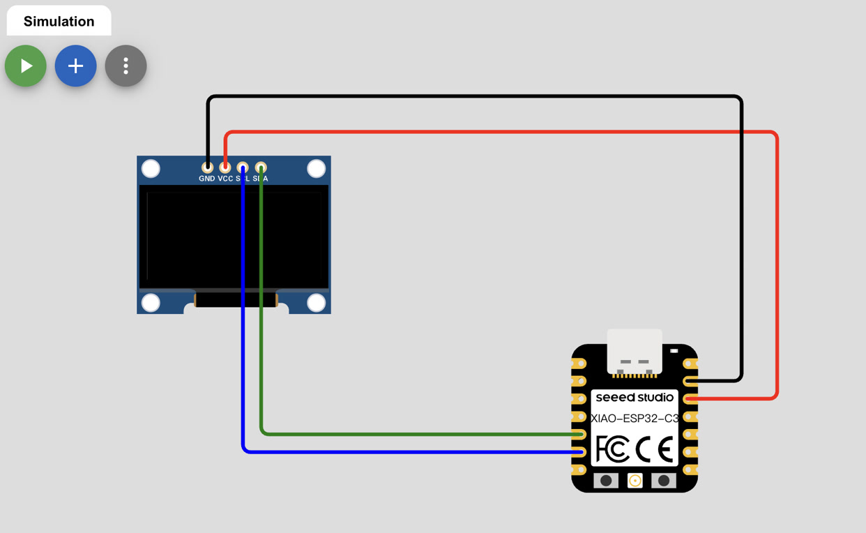
Now I started to do the simulation on Wokwi. I started a new project on the platform, and added the SSD1306 OLED display.
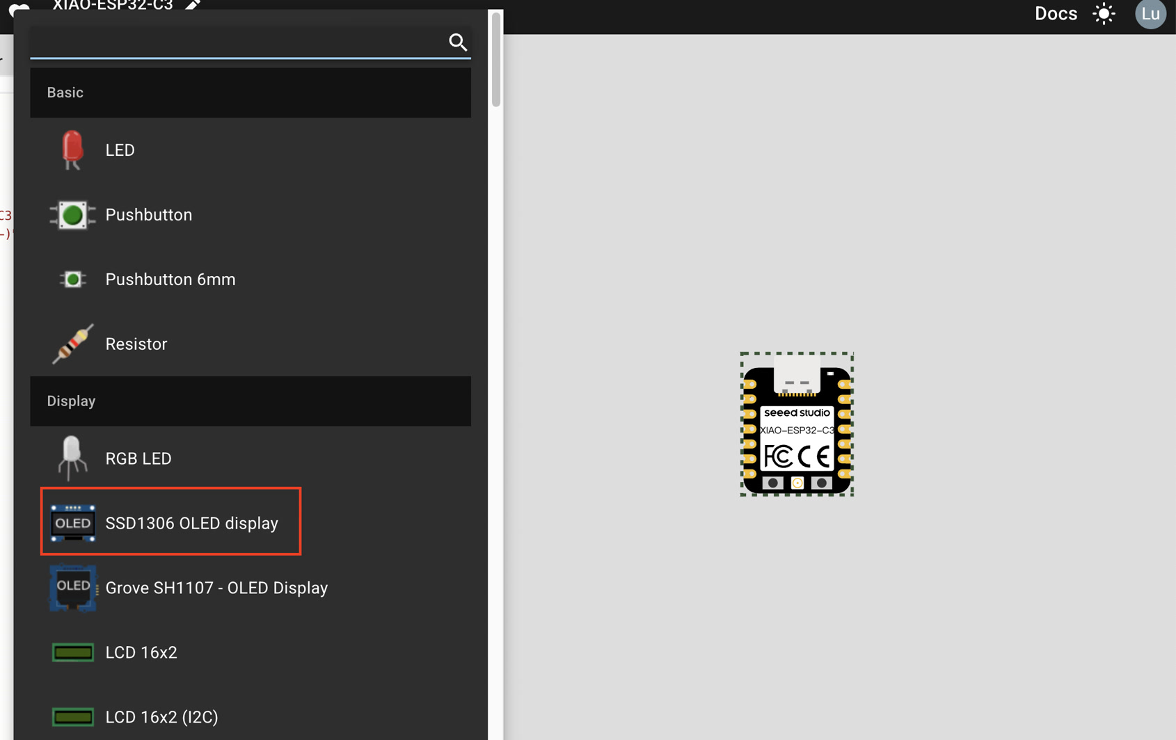
To enable visual output, I connected a 0.96" SSD1306 OLED Display to the XIAO ESP32C3 using the I2C (Inter-Integrated Circuit) protocol. This protocol is ideal as it only requires two signal wires to communicate.
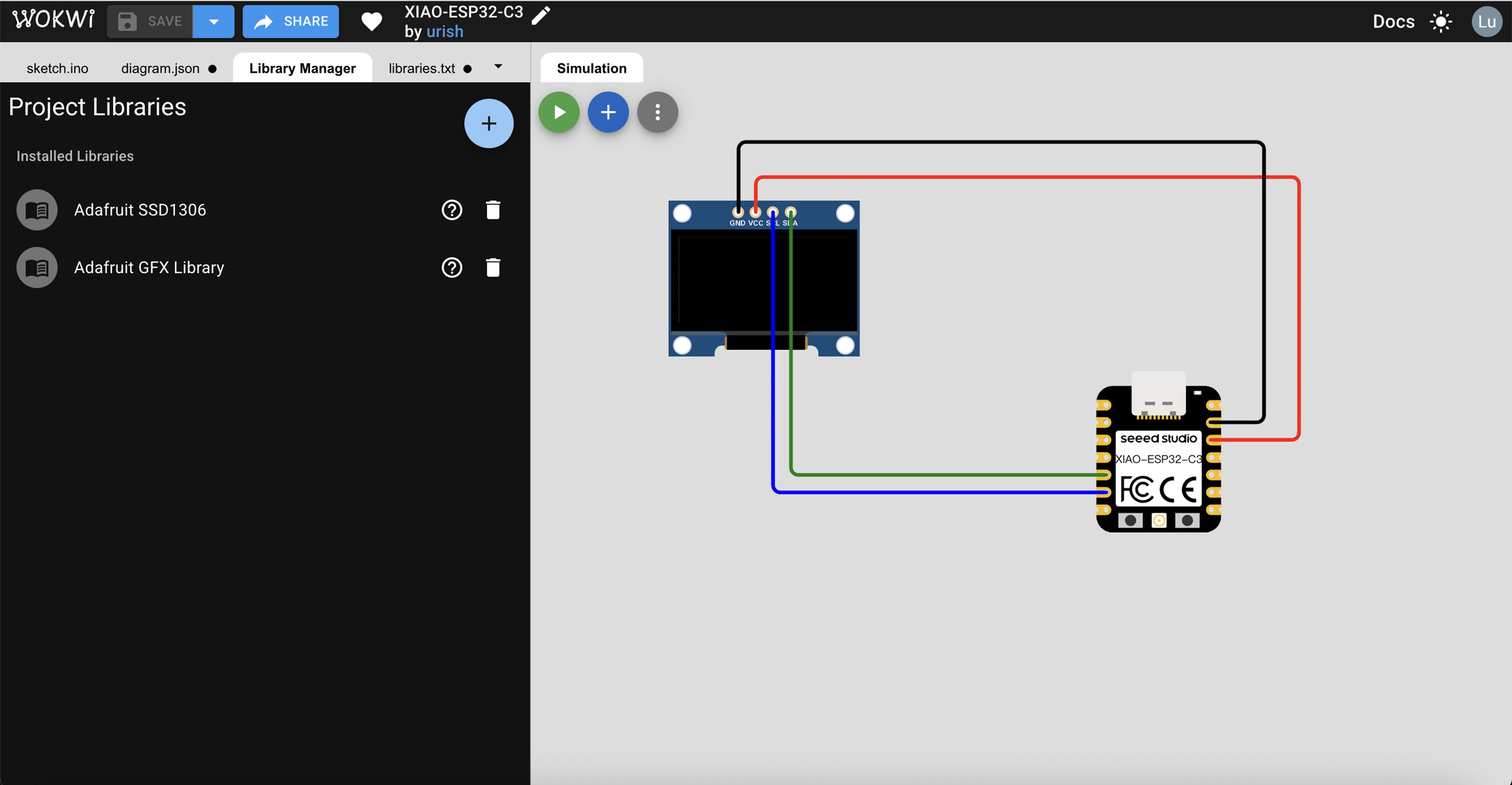
Before writing the code, I configured the software environment by adding the necessary drivers. In the Wokwi Library Manager, I searched for and installed the Adafruit SSD1306 and Adafruit GFX libraries. These libraries provide the essential functions to communicate with the OLED hardware and render text and shapes on the screen.
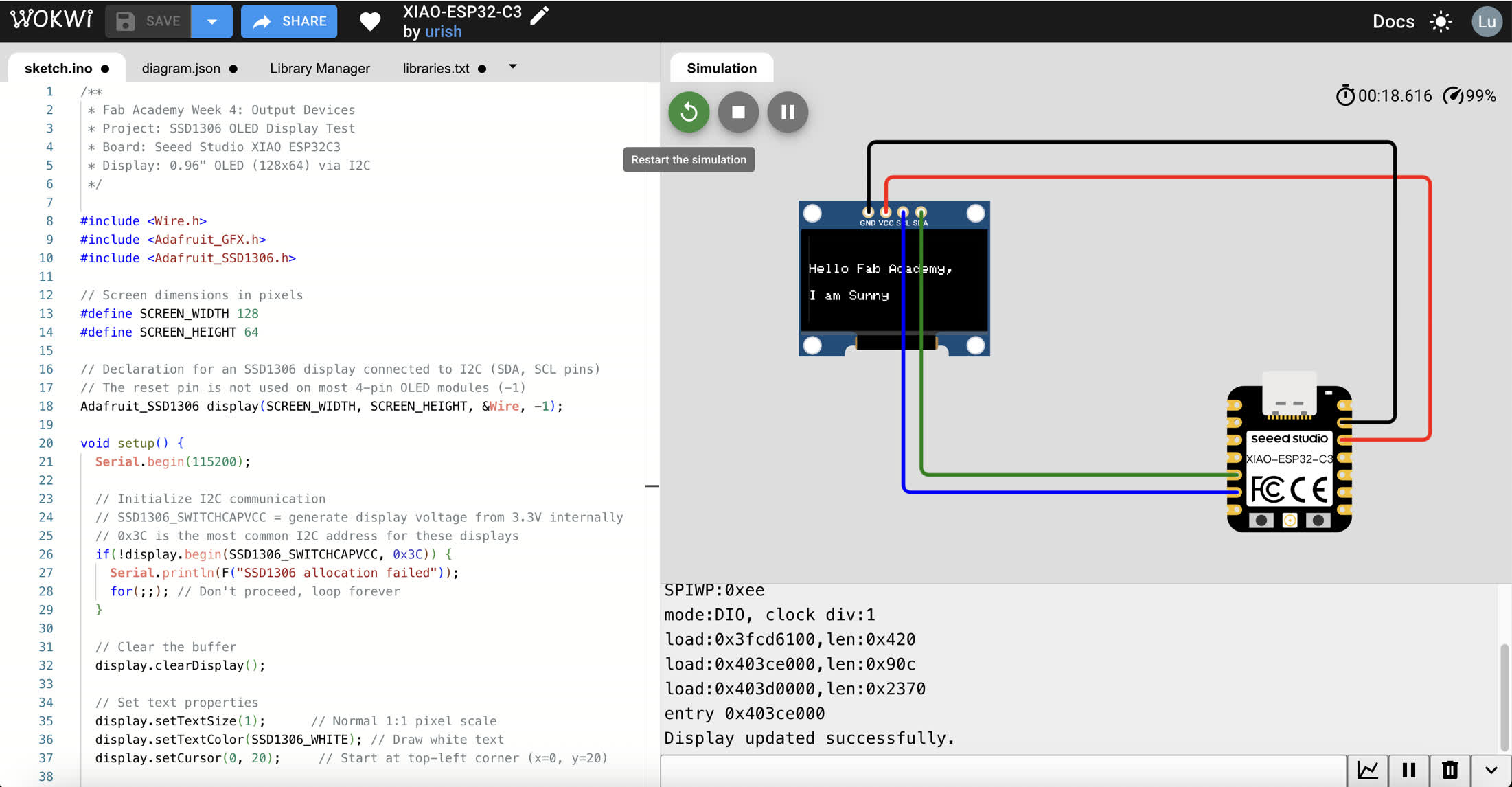
Then I asked Google Gemini to write the code, I wanted the OLED display to show "Hello Fab Academy, I am Sunny" on the screen.
/**
Fab Academy Week 4: Output Devices
Project: SSD1306 OLED Display Test
Board: Seeed Studio XIAO ESP32C3
Display: 0.96" OLED (128x64) via I2C
*/

#include <Wire.h>
#include <Adafruit_GFX.h>
#include <Adafruit_SSD1306.h>

// Screen dimensions in pixels
#define SCREEN_WIDTH 128
#define SCREEN_HEIGHT 64

// Declaration for an SSD1306 display connected to I2C (SDA, SCL pins)
// The reset pin is not used on most 4-pin OLED modules (-1)
Adafruit_SSD1306 display(SCREEN_WIDTH, SCREEN_HEIGHT, &Wire, -1);

void setup() {
  Serial.begin(115200);

  // Initialize I2C communication
  // SSD1306_SWITCHCAPVCC = generate display voltage from 3.3V internally
  // 0x3C is the most common I2C address for these displays
  if(!display.begin(SSD1306_SWITCHCAPVCC, 0x3C)) {
    Serial.println(F("SSD1306 allocation failed"));
    for(;;); // Don't proceed, loop forever
  }

  // Clear the buffer
  display.clearDisplay();

  // Set text properties
  display.setTextSize(1);      // Normal 1:1 pixel scale
  display.setTextColor(SSD1306_WHITE); // Draw white text
  display.setCursor(0, 20);     // Start at top-left corner (x=0, y=20)

  // Print the specific message
  display.println(F("Hello Fab Academy,"));
  display.setCursor(0, 40);
  display.println(F("I am Sunny"));

  // Crucial: Push the buffer to the actual hardware display
  display.display();

  Serial.println("Display updated successfully.");
}

void loop() {
  // Static display, no action needed in loop
}
Then the display showed the content of "Hello Fab Academy, I am Sunny".
XIAO-ESP32-C3 OLED display - Wokwi ESP32, STM32, Arduino Simulator
What I learned during the process of simulation:
Set 220Ω of Resistor:
I calculated the resistor value using Ohm's Law ($R = V/I$). With a 3.3V source from the XIAO ESP32C3 and a 2.0V forward voltage drop for the Red LED, a 220Ω resistor limits the current to approximately 6mA. This is the "sweet spot"—bright enough for simulation and safe enough to protect the GPIO pins.
LED Polarity & Continuity:
I confirmed that LEDs are directional; the Anode (bent leg) must be connected to the signal source. I also learned that 4-pin tactile buttons are internally connected in pairs, requiring a diagonal or specific vertical connection to function as a bridge when pressed.
Pin Mapping (2 vs. D2):
A crucial discovery was the difference between using raw GPIO numbers and board-specific macros. Using D2 ensured that the compiler correctly mapped the logic to the physical pin on the Seeed Studio XIAO, avoiding conflicts with multiplexed functions like UART TX.
Input Pull-up Strategy:
By utilizing pinMode(BUTTON_PIN, INPUT_PULLUP), I eliminated the need for an external physical resistor for the button. This led to an Active-Low logic, where the software detects a button press as a LOW signal.
Serial Monitor Debugging:
When the physical LED didn't react due to simulation lag or wiring micro-errors, the Serial Monitor provided the necessary feedback. Printing states (e.g., "LED ON") allowed me to verify that my code logic was 100% correct before troubleshooting the physical components.
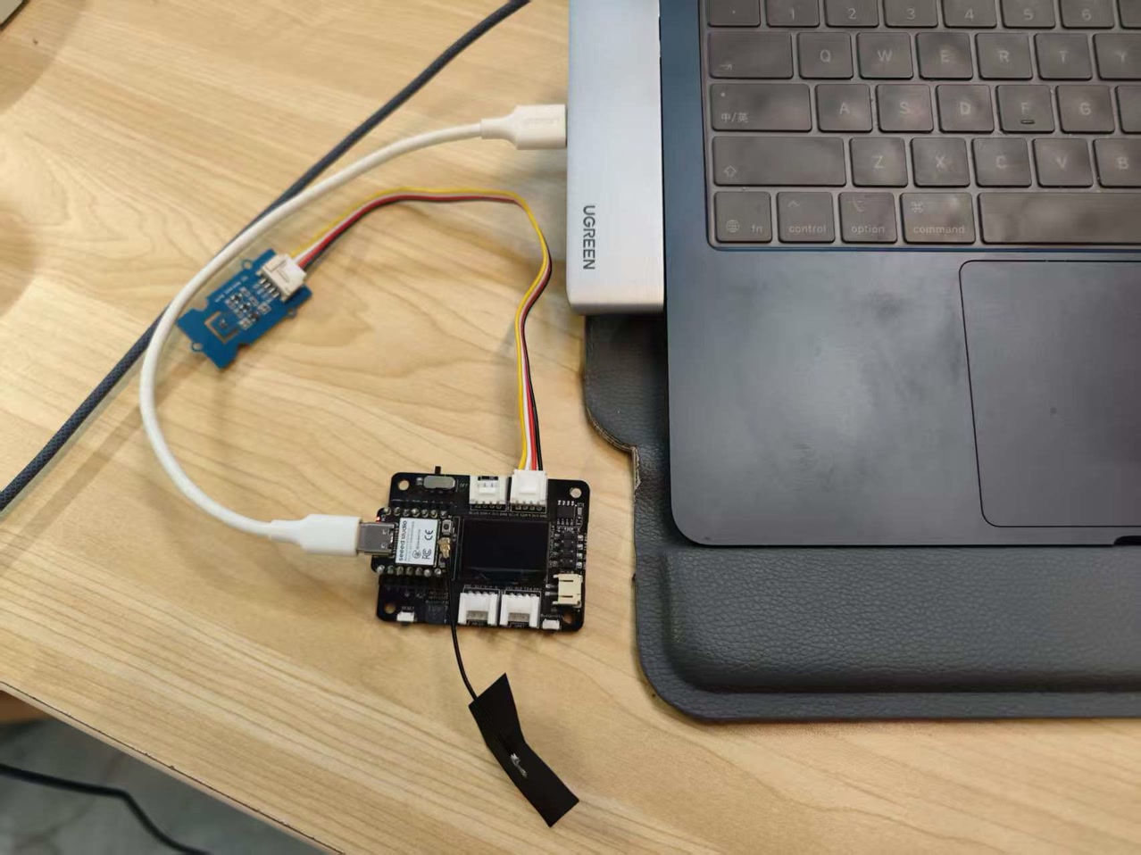
3. Hardware Implementation: Real-time Weather Station
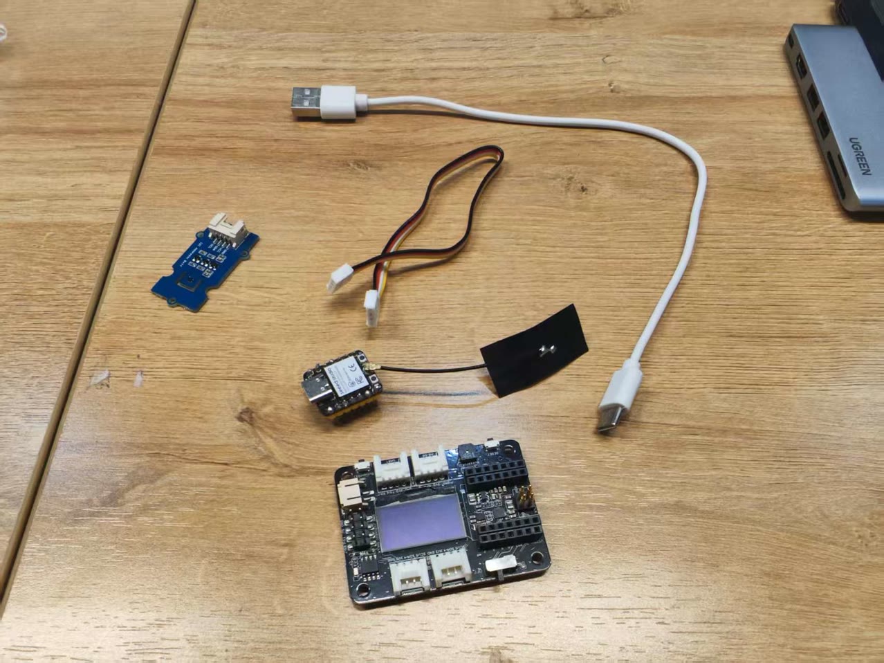
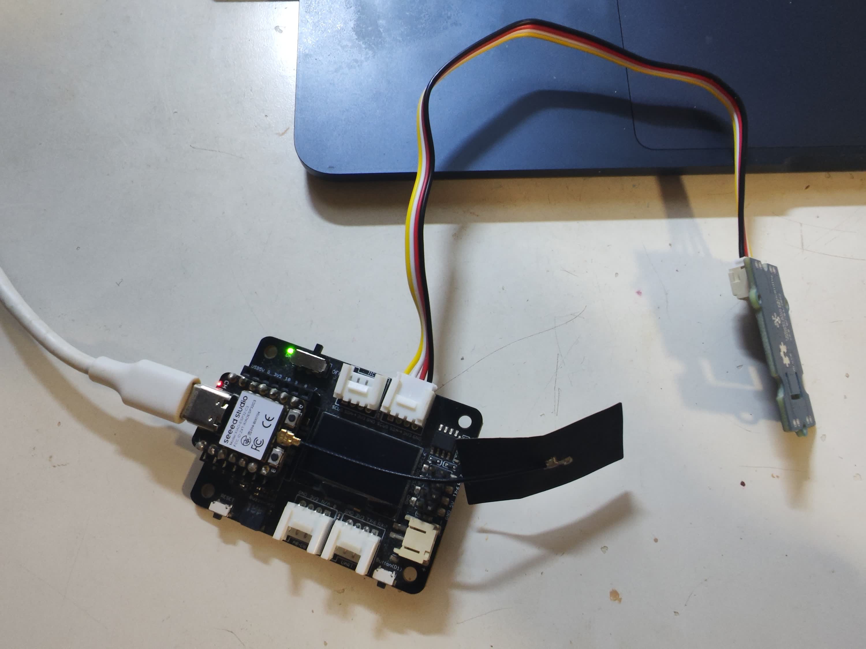
To complete the physical prototype, I integrated the XIAO ESP32C3 with the XIAO Expansion Board and the Grove SHT40 Sensor. This setup allows for a standalone environmental monitor that displays real-time data without needing a PC connection.
Component Integration
I utilized the XIAO ecosystem's modular design for a clean and reliable assembly:
- MCU Installation: The XIAO ESP32C3 was mounted onto the Expansion Board's female headers.
- Sensor Connection: The SHT40 sensor was connected to the Expansion Board's hardware I2C port using a universal Grove cable.
- Display: I utilized the onboard 0.96-inch OLED which is already located on the XIAO expansion board for data visualization, thus I don't need to add a new separated output display.
- Power & Data: A USB-C Data Cable was used to connect the XIAO to my Mac for firmware flashing, serial debugging, and consistent power supply.
Wiring Strategy & Protocol
Instead of using a traditional breadboard and jumper wires, I opted for the Grove system to minimize connection errors. Both the SHT40 sensor and the OLED display share the same I2C bus (SDA on D4, SCL on D5). Since each device has a unique I2C address, the ESP32C3 can communicate with the sensor to fetch data and simultaneously update the screen.
Power and Portability
The entire system is powered via a single USB-C cable. Due to the low power consumption of the SHT40 and the OLED, the 3.3V rail from the XIAO provides sufficient current for stable operation.
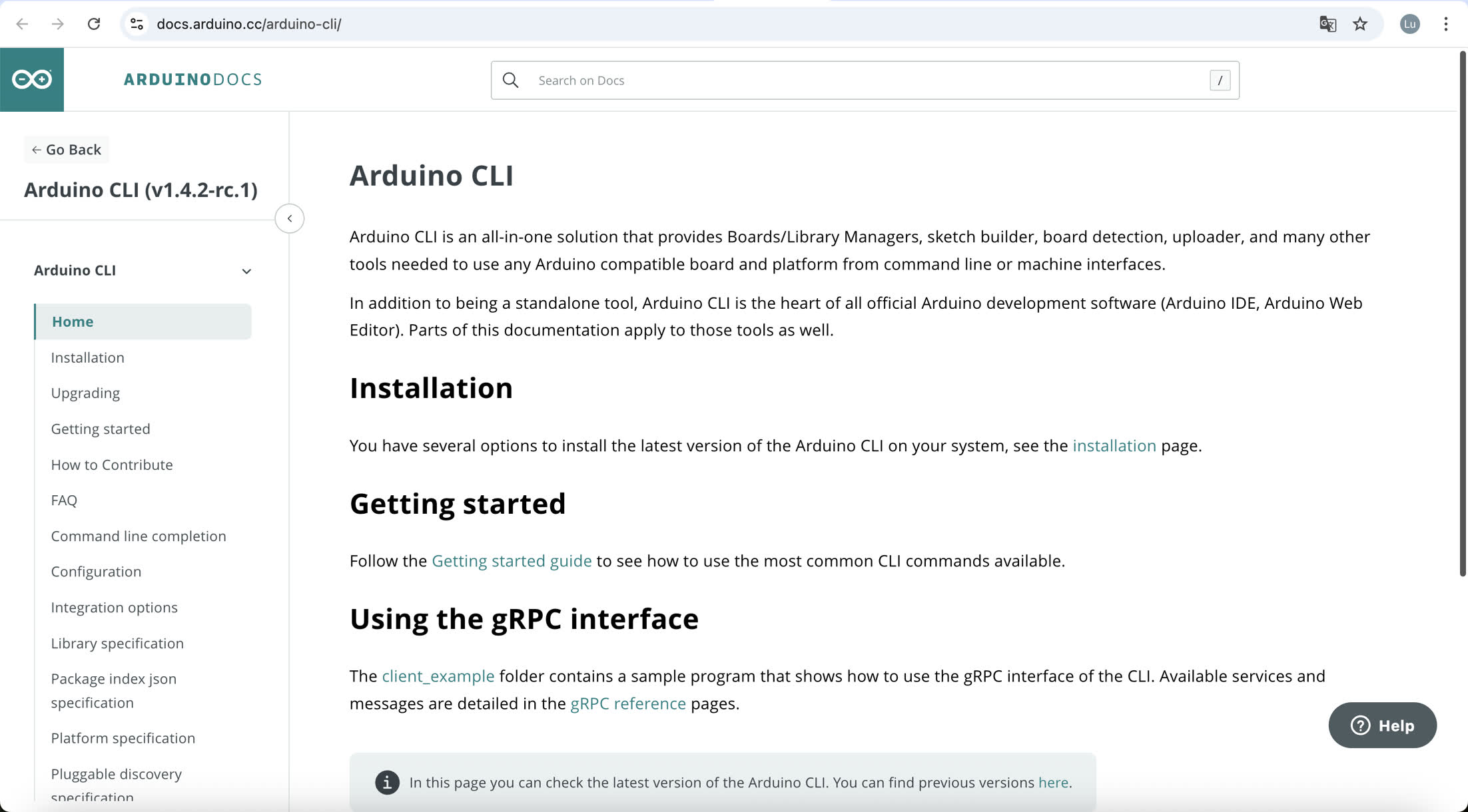
Software for programming
To maintain a lightweight and professional development workflow, I installed the Arduino CLI using the macOS Terminal. This allows me to manage boards and libraries without a heavy graphical interface.
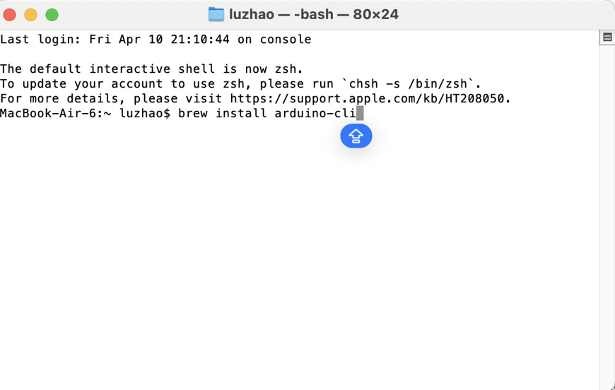
I used Homebrew (the macOS package manager) to install the CLI engine directly:
After the process finished, I verified that the tool was correctly added to my system path by checking its version:
Successfully seeing arduino-cli Version: 1.4.1 confirmed that the software was ready to use.

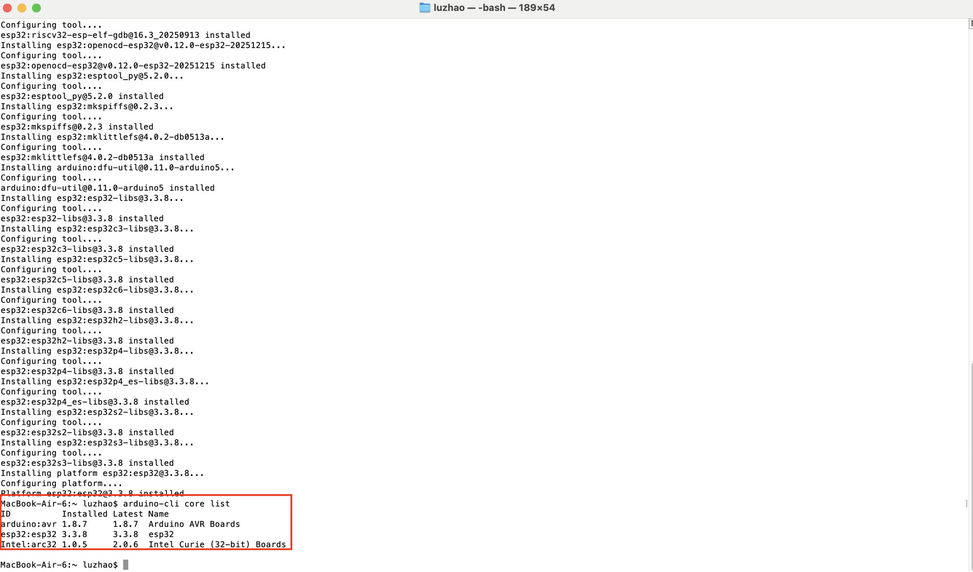
Since the XIAO ESP32-C3 is not a default board, I configured the CLI to recognize the Espressif repository and installed the necessary core:
4.Verification of ESP32 supportAfter long time of downloading and installation, it worked. I put "arduino-cli board list" in the terminal to sea if esp32:esp32 is coming, now it succeeded.
Programming on Cursor for Arduino CLI
-
I used the USB cable to connect the XIAO hardware kit to my computer.
-
I initiated the project by opening a new window in Cursor and creating a dedicated workspace folder named weather station.
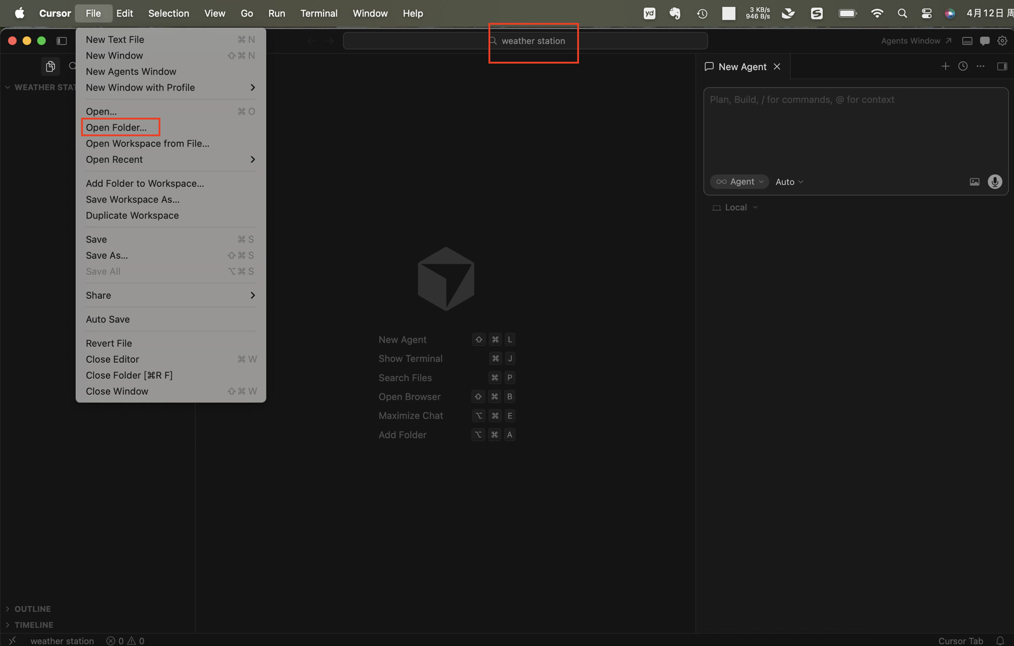
-
Then I provided Cursor with a specific set of requirements to ensure the code matched my hardware setup: Generate an Arduino sketch for XIAO ESP32C3 with XIAO Expansion Board.
/*
 * XIAO ESP32C3 + Seeed XIAO Expansion Board
 * SHT40 (I2C) + SSD1306 128x64 OLED (I2C)
 *
 * Expansion board I2C: SDA = D4 (GPIO6), SCL = D5 (GPIO7)
 *
 * NOTE — Expansion "ON" green LED:
 *   Seeed docs: flashing = no LiPo / not charging; solid = charging.
 *   On USB-only (no battery) the green LED often blinks — that is normal.
 *
 * Libraries: Adafruit SHT4x, Adafruit SSD1306, Adafruit GFX, Adafruit BusIO
 */

#include <Wire.h>
#include <Adafruit_GFX.h>
#include <Adafruit_SSD1306.h>
#include <Adafruit_SHT4x.h>

static const int PIN_I2C_SDA = 6;  // D4
static const int PIN_I2C_SCL = 7;  // D5

#define SCREEN_WIDTH 128
#define SCREEN_HEIGHT 64
#define OLED_RESET -1

Adafruit_SSD1306 display(SCREEN_WIDTH, SCREEN_HEIGHT, &Wire, OLED_RESET);
Adafruit_SHT4x sht4;

bool sht4_ok = false;
uint8_t oled_addr_used = 0;

static void i2c_scan_serial() {
  Serial.println(F("I2C scan (SDA=GPIO6, SCL=GPIO7):"));
  uint8_t n = 0;
  for (uint8_t a = 1; a < 127; a++) {
    Wire.beginTransmission(a);
    if (Wire.endTransmission() == 0) {
      Serial.print(F("  0x"));
      if (a < 16) Serial.print('0');
      Serial.println(a, HEX);
      n++;
    }
  }
  if (n == 0) {
    Serial.println(F("  (no devices — check XIAO seated, USB power, pins)"));
  }
}

static bool init_oled() {
  const uint8_t addrs[] = {0x3C, 0x3D};
  for (uint8_t i = 0; i < sizeof(addrs); i++) {
    // Some modules / long wires need a slower bus during init
    Wire.setClock(50000);
    if (display.begin(SSD1306_SWITCHCAPVCC, addrs[i])) {
      oled_addr_used = addrs[i];
      return true;
    }
  }
  return false;
}

void setup() {
  Serial.begin(115200);
  delay(300);
  Serial.println();
  Serial.println(F("=== weather_station_oled_sht40 ==="));
  Serial.println(F("Board must be XIAO ESP32C3; I2C SDA=GPIO6 (D4), SCL=GPIO7 (D5)."));
  Serial.println(F("Open Serial Monitor at 115200 baud to see I2C scan if screen is blank."));
  Serial.println();

  Wire.begin(PIN_I2C_SDA, PIN_I2C_SCL);
  Wire.setClock(100000);

  i2c_scan_serial();

  if (!init_oled()) {
    Serial.println(F("SSD1306 not found at 0x3C or 0x3D."));
    Serial.println(F("If scan shows a device, note its address and wiring."));
    Serial.println(F("If scan shows NO devices: re-seat XIAO on expansion, USB power, check board type."));
    while (true) {
      delay(5000);
      i2c_scan_serial();
    }
  }
  Serial.print(F("SSD1306 OK at 0x"));
  if (oled_addr_used < 16) Serial.print('0');
  Serial.println(oled_addr_used, HEX);

  display.clearDisplay();
  display.setTextColor(SSD1306_WHITE);
  display.setTextSize(1);
  display.setCursor(0, 0);
  display.println(F("OLED OK"));
  display.display();

  sht4_ok = sht4.begin();
  if (sht4_ok) {
    sht4.setPrecision(SHT4X_HIGH_PRECISION);
    sht4.setHeater(SHT4X_NO_HEATER);
    display.println(F("SHT40 OK"));
  } else {
    display.println(F("SHT40 missing"));
    display.println(F("(plug Grove I2C)"));
    Serial.println(F("SHT4x not found — OLED still works; add sensor on I2C."));
  }
  display.display();
  delay(1500);

  Wire.setClock(400000);
}

void loop() {
  float t_c = NAN;
  float rh = NAN;

  if (sht4_ok) {
    sensors_event_t humidity, temp;
    sht4.getEvent(&humidity, &temp);
    t_c = temp.temperature;
    rh = humidity.relative_humidity;
  }

  display.clearDisplay();
  display.setTextSize(2);
  display.setCursor(0, 4);
  if (sht4_ok) {
    display.print(F("T "));
    display.print(t_c, 1);
    display.println(F(" C"));
    display.setCursor(0, 36);
    display.print(F("RH "));
    display.print(rh, 1);
    display.println(F(" %"));
  } else {
    display.setTextSize(1);
    display.setCursor(0, 0);
    display.println(F("No SHT40"));
    display.println(F("Scan Serial"));
    display.println(F("115200 baud"));
  }
  display.display();

  if (sht4_ok) {
    Serial.print(F("T = "));
    Serial.print(t_c, 2);
    Serial.print(F(" C, RH = "));
    Serial.print(rh, 2);
    Serial.println(F(" %"));
  }

  delay(2000);
}
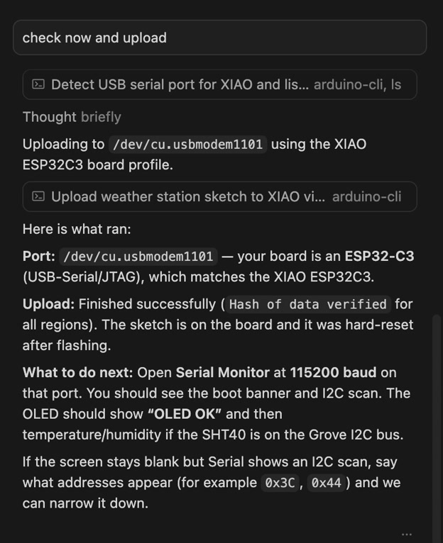
Note: I2C Address Identification This system uses two I2C devices connected to the same bus:
- SSD1306 OLED display — I2C address 0x3C
- SHT40 sensor — I2C address 0x44 The OLED address is detected in the code through an initialization routine that checks both 0x3C and 0x3D. The SHT40 address is handled internally by the Adafruit SHT4x library and is defined by the manufacturer as 0x44. Because each device has a unique address, both components can communicate simultaneously on the same I2C bus without conflict.
However it did not show up the data on the display; the display was still black, nothing happened.
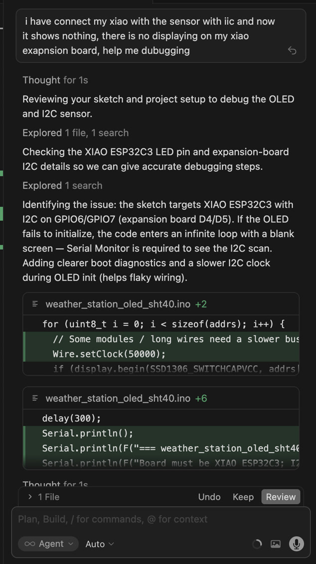
To resolve this, I initiated a debugging session with Cursor AI, which suggested two critical hardware checks: verifying the integrity of the USB cable and performing a manual bootloader reset.
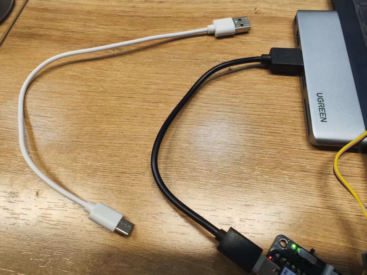
Cable Verification: I discovered that the initial cable was power-only. I replaced it with a high-quality USB-C data cable to ensure a stable communication link between my Mac and the board.
Manual Bootloader Mode: To resolve the connection timeout, I followed the Seeed Studio XIAO ESP32C3 Wiki instructions to manually enter bootloader mode.
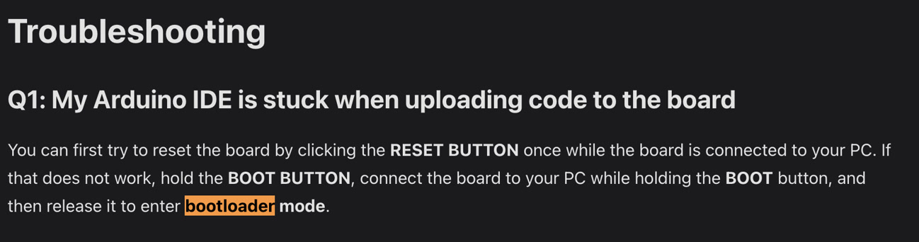
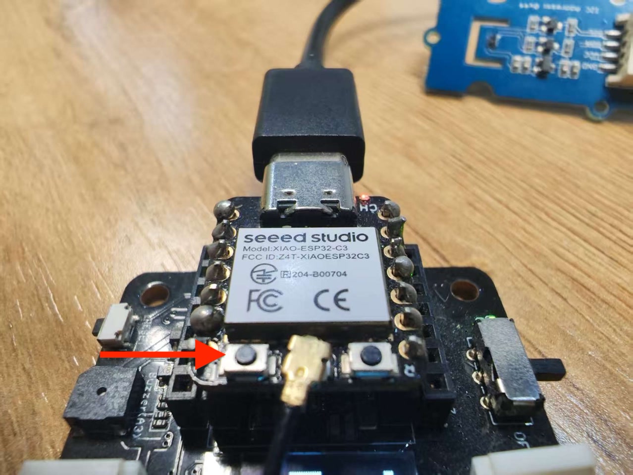
It seemed successful this time, and I can see the temperature and humidity date from the OLED display!
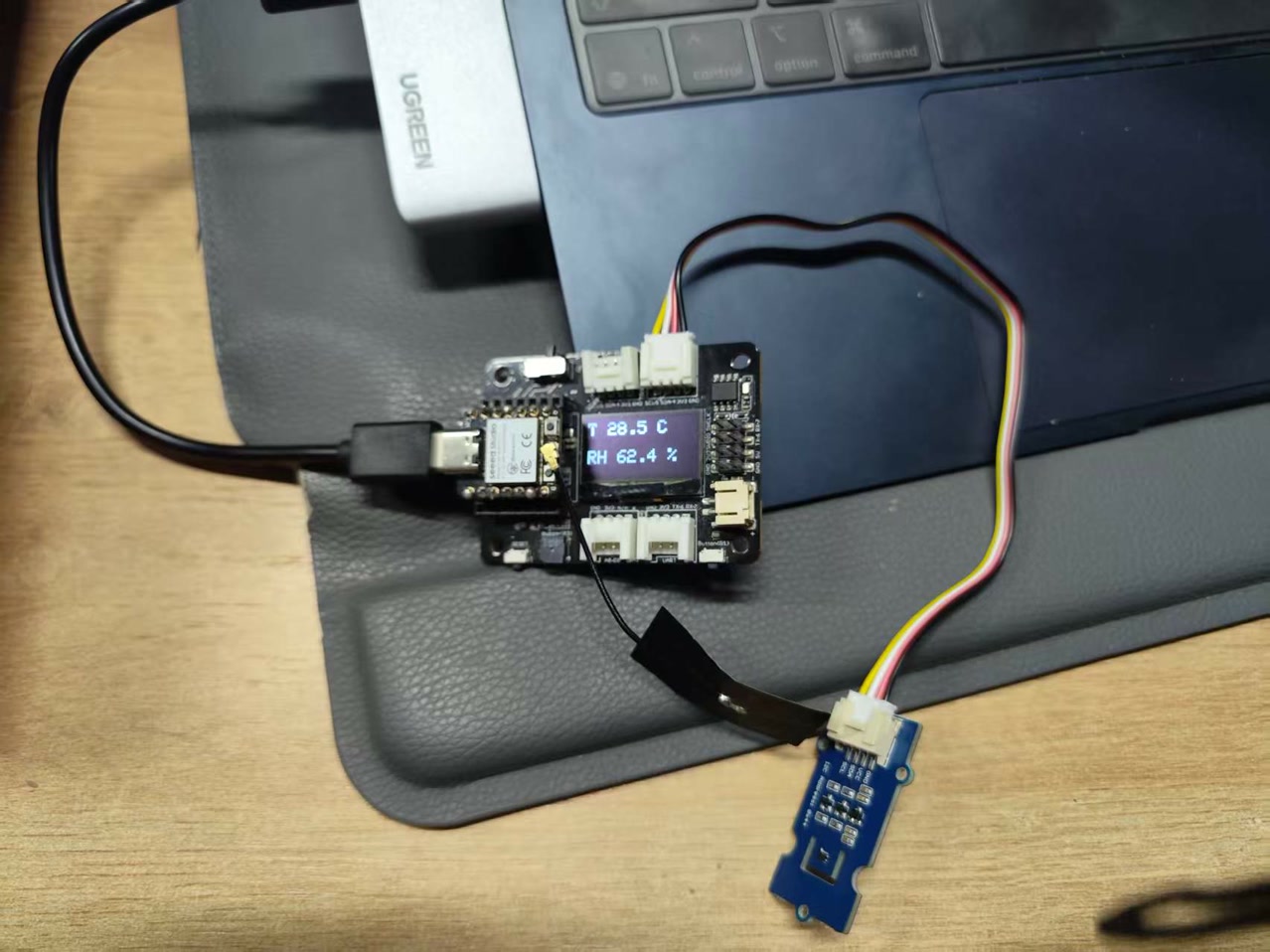
I tested the responsiveness of the system by blowing air toward the SHT40 sensor to observe real-time changes in the readings. As shown in the video, the humidity and temperature values on the OLED screen increased immediately upon detection, confirming that the sensor and the code were functioning correctly.