Week 2: Computer Aided Design
This week, the goal is to explore various Computer-Aided Design (CAD) tools, covering both 2D and 3D modeling. For a beginner without a technical background, understanding these digital tools is the first step toward physical fabrication. In this documentation, I will first detail my experience with 2D raster and vector graphics, followed by my initial steps into 3D parametric design.
1. Understanding Raster vs. Vector (2D)
Before diving into the tools, it is important to distinguish these two formats. Raster graphics (or bitmaps) are composed of pixels. When scaled up, they lose quality and become pixelated, making them best for photographs. Vector graphics are composed of mathematical paths like lines and curves. They can be scaled infinitely without losing quality, which is essential for machines like laser cutters.
2. Raster Graphics with Photopea
For raster image processing, I chose Photopea, a powerful web-based alternative to Adobe Photoshop/GIMP. As I am working in a fast-paced environment and catching up on my Fab Academy progress, I prefer Photopea because it is browser-based and highly efficient for quick tasks like cropping and web optimization.
My Workflow in Photopea:
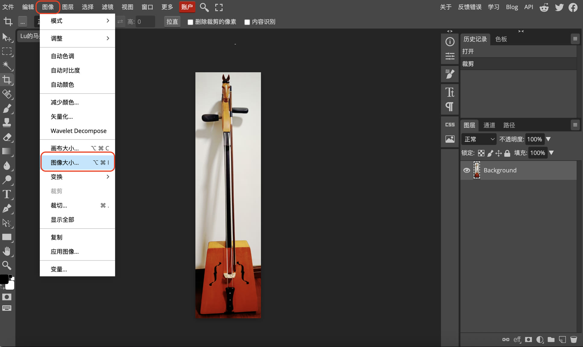
Open the website of Photopea: https://www.photopea.com/
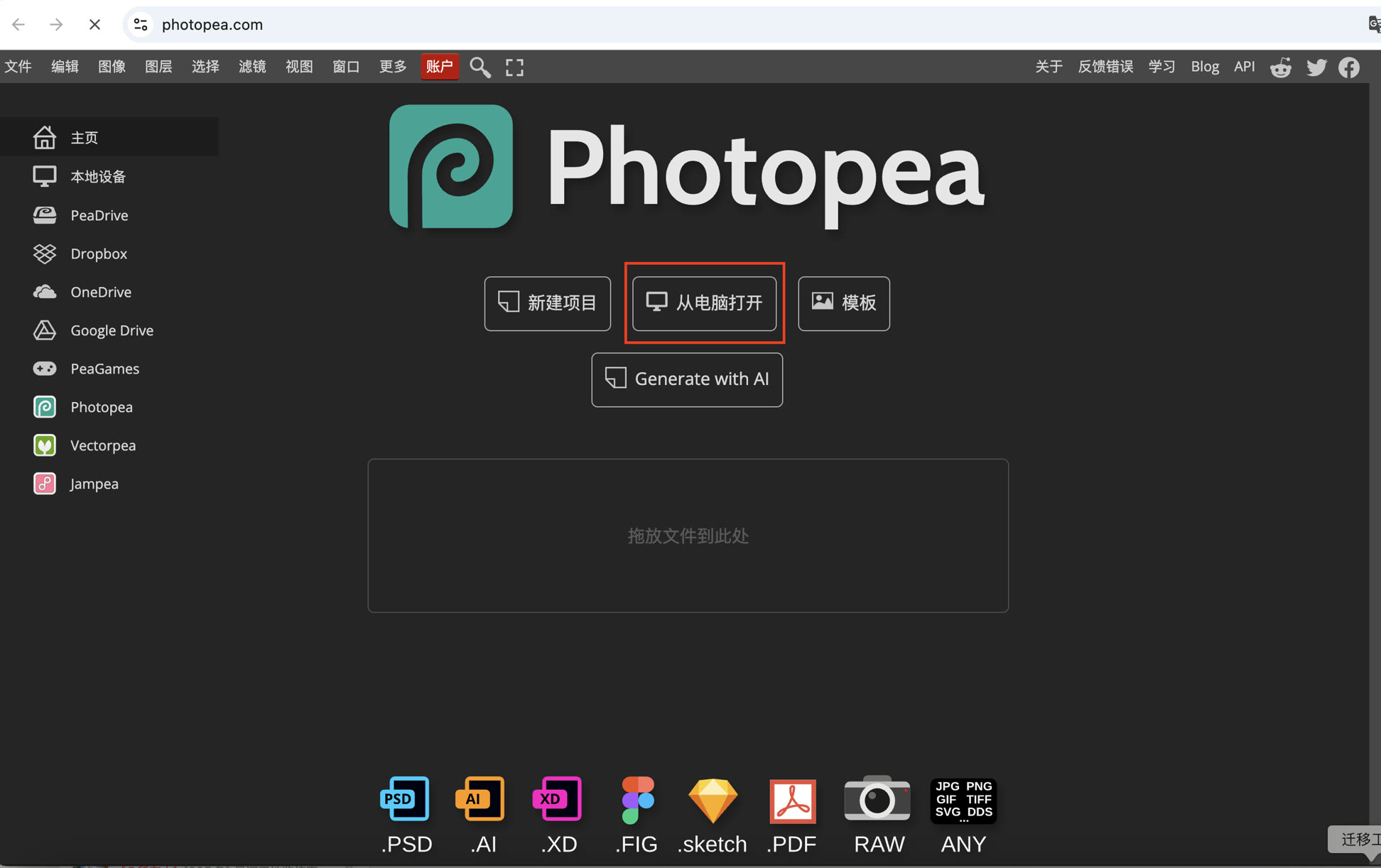
Click Open from Computer, and I imported a photo of my Morin Khuur (Mongolian musical instrument).
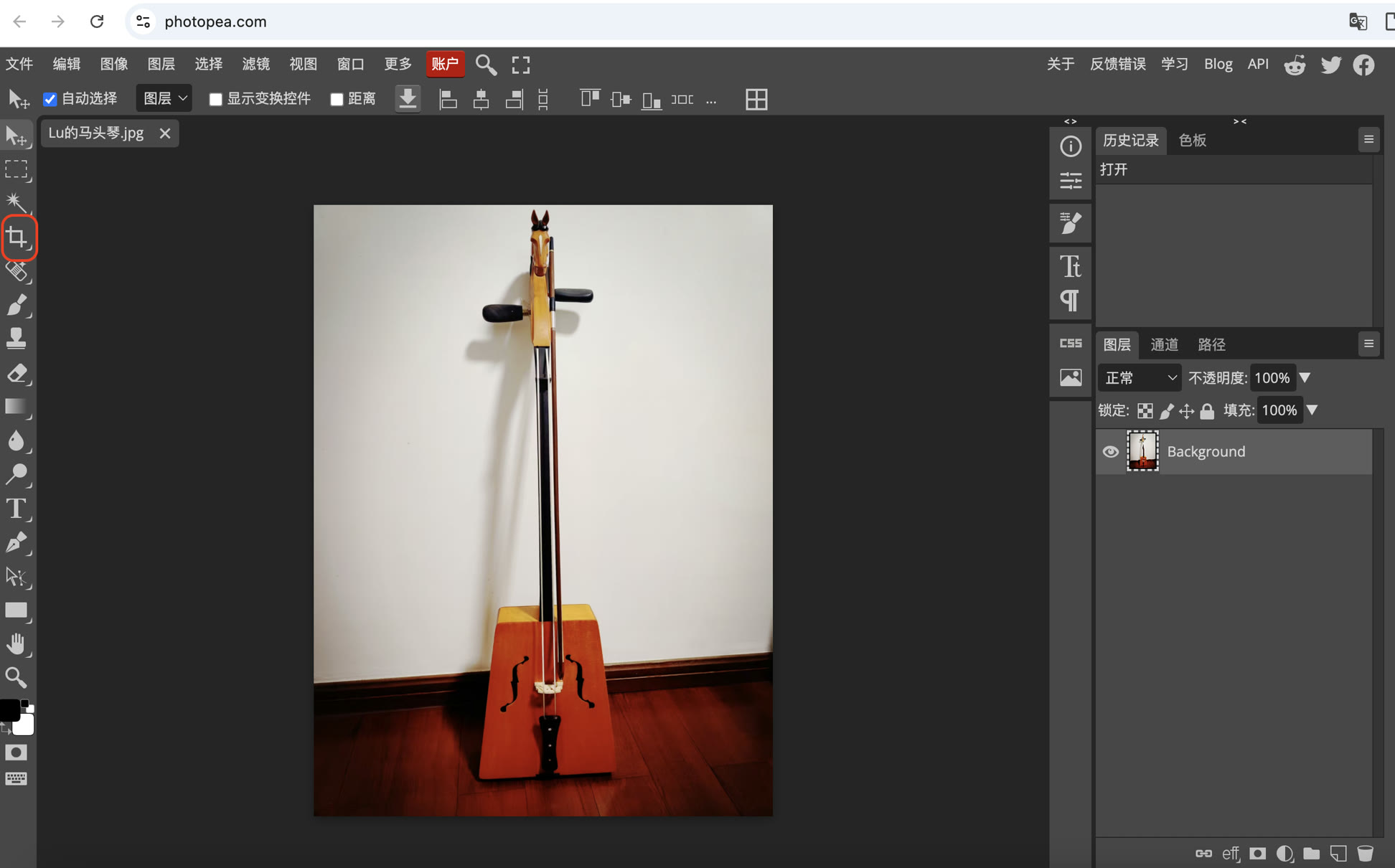
I used the Crop Tool on the left to remove unnecessary background clutter and focus on the main subject.
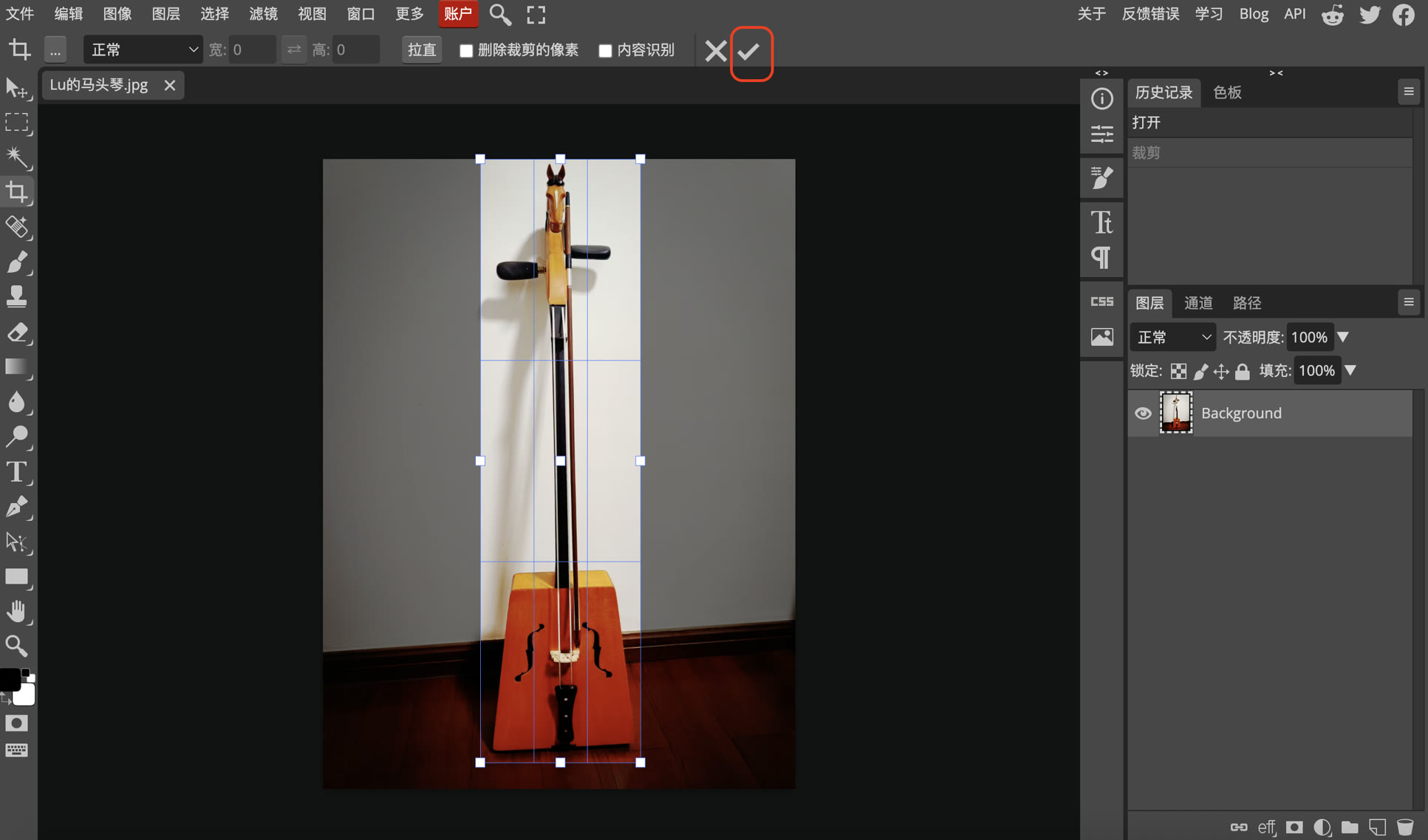
I dragged the crop box to define the cropping area, then click ✅ to confirm.
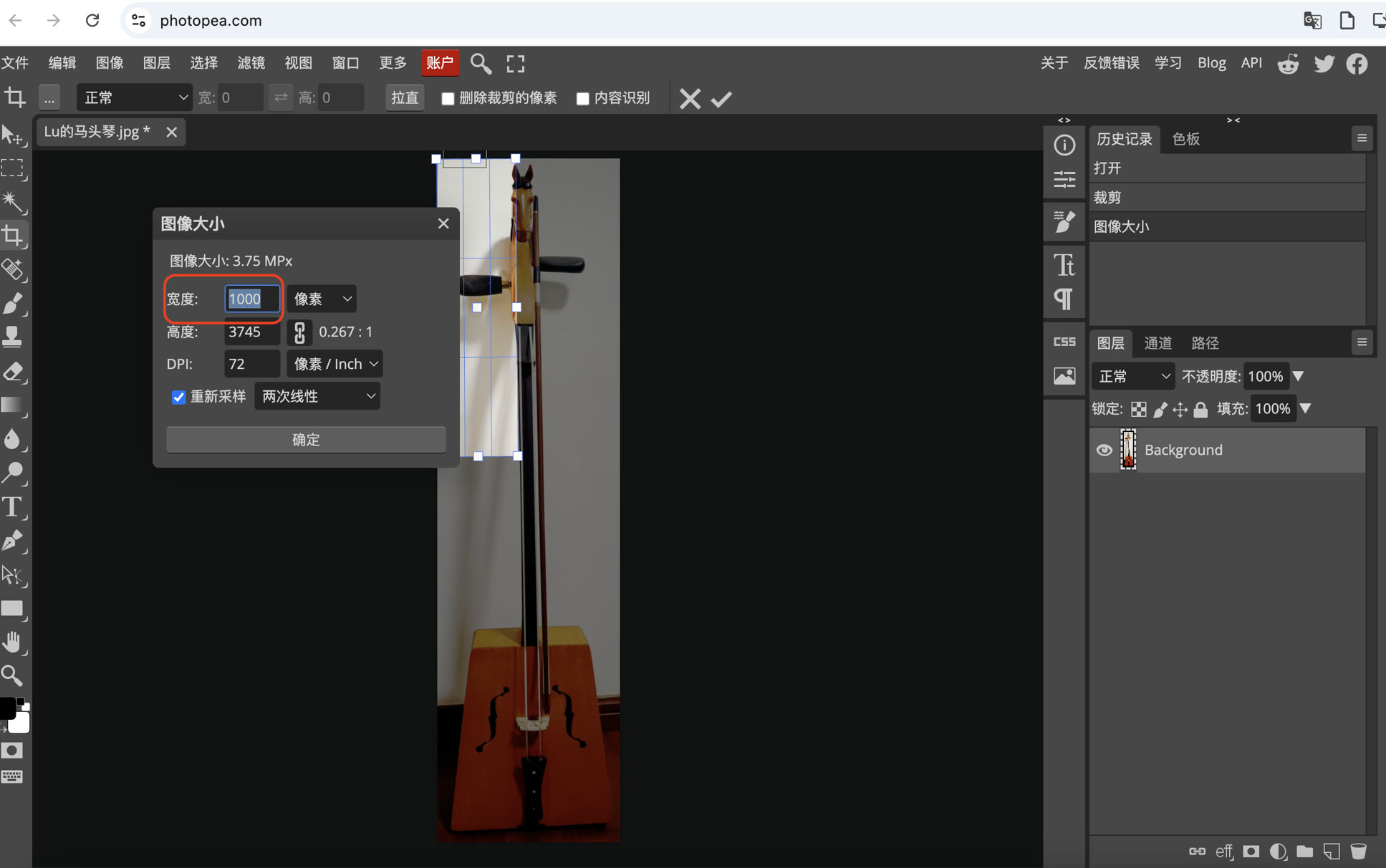
To ensure my documentation site loads quickly, I used the Image Size menu to scale the width from 435 to 1000px. This is a critical step in web performance optimization.
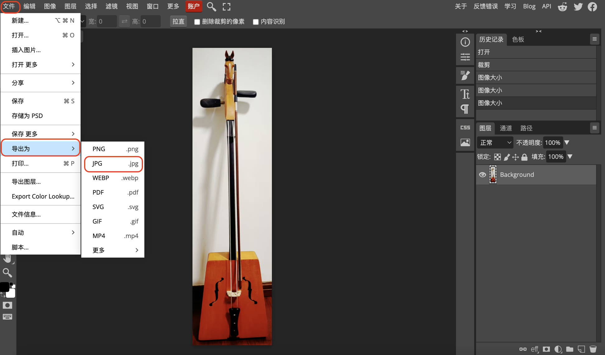
Then I exported the file as JPG.
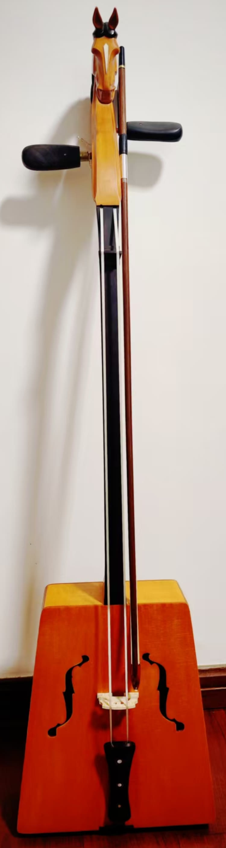
Finally, I got my cropped photo of my Morin Khuur, without unnecessary background information.
3. Vector Graphics with Inkscape
For vector design, I used Inkscape, the most popular open-source vector graphics editor in the Fab Lab community. Inkscape is the standard for 2D digital fabrication as it allows me to create precise paths that machines can follow.
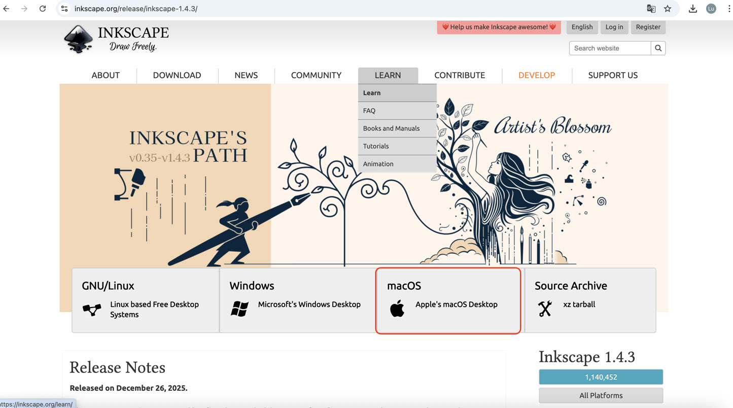
First of all, I install the Inkscape for macOS.
My Workflow in Inkscape:
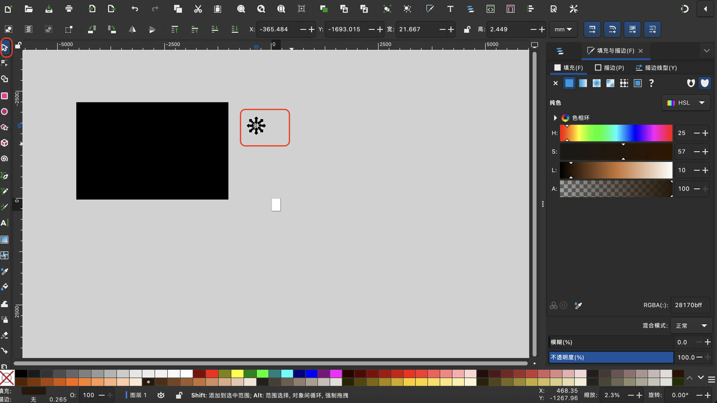
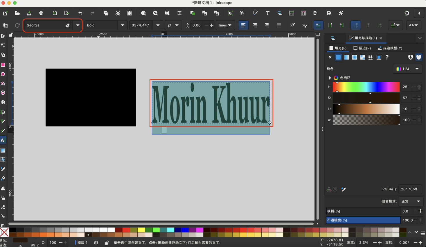
I started by creating a simple logo "Morin Khuur" using geometric shapes and text.
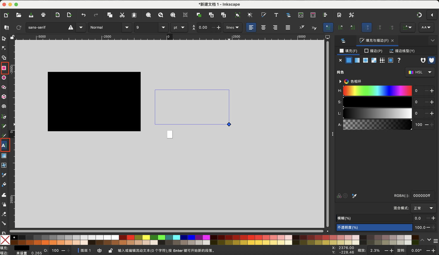
It is strange that I cannot see my text, which seemed different from my experience in other editable tools; I searched the video tutorial and found that after typing the text, I need to click the arrow on the left and stretch it to see my text.
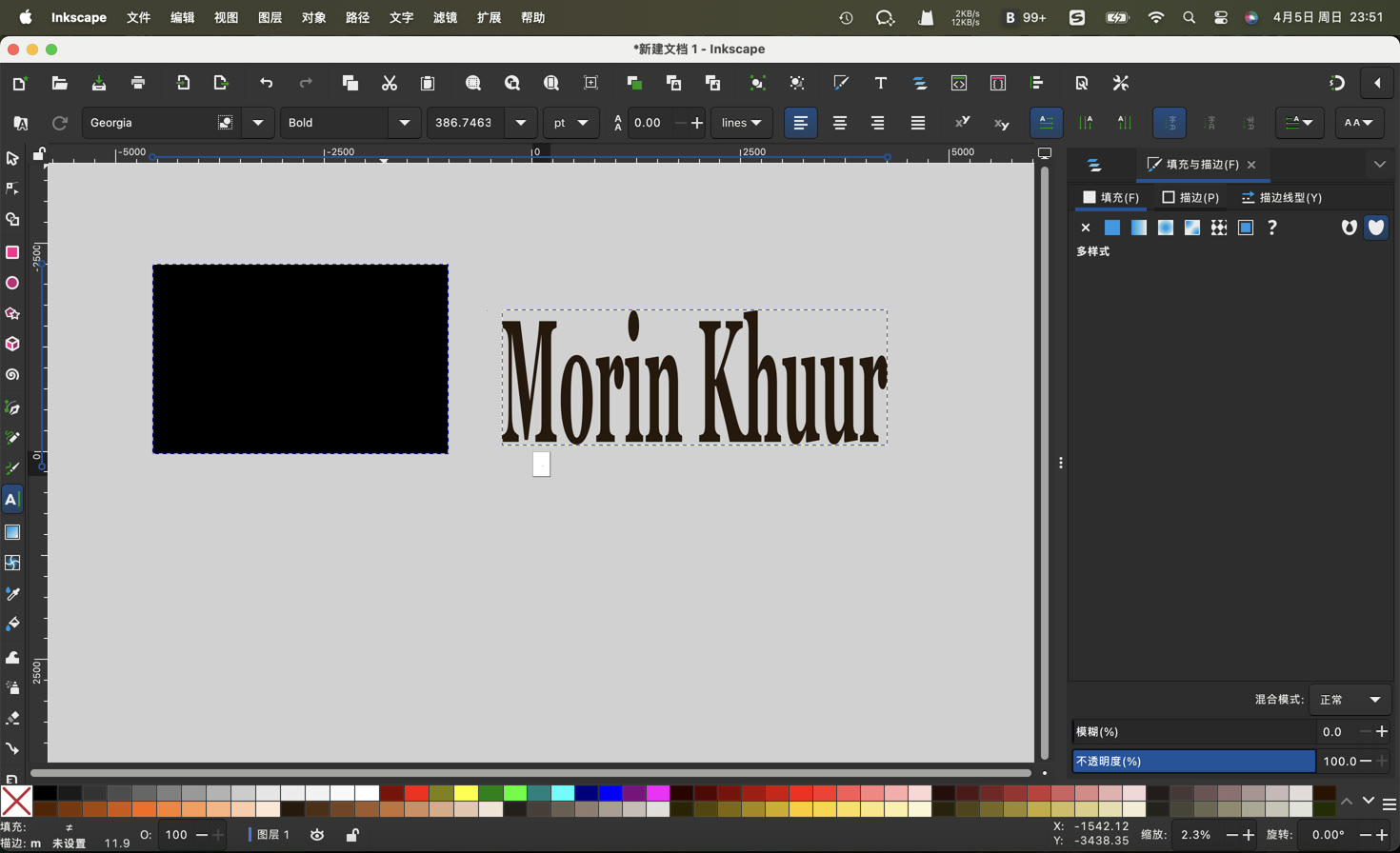
Then I changed the font of text.
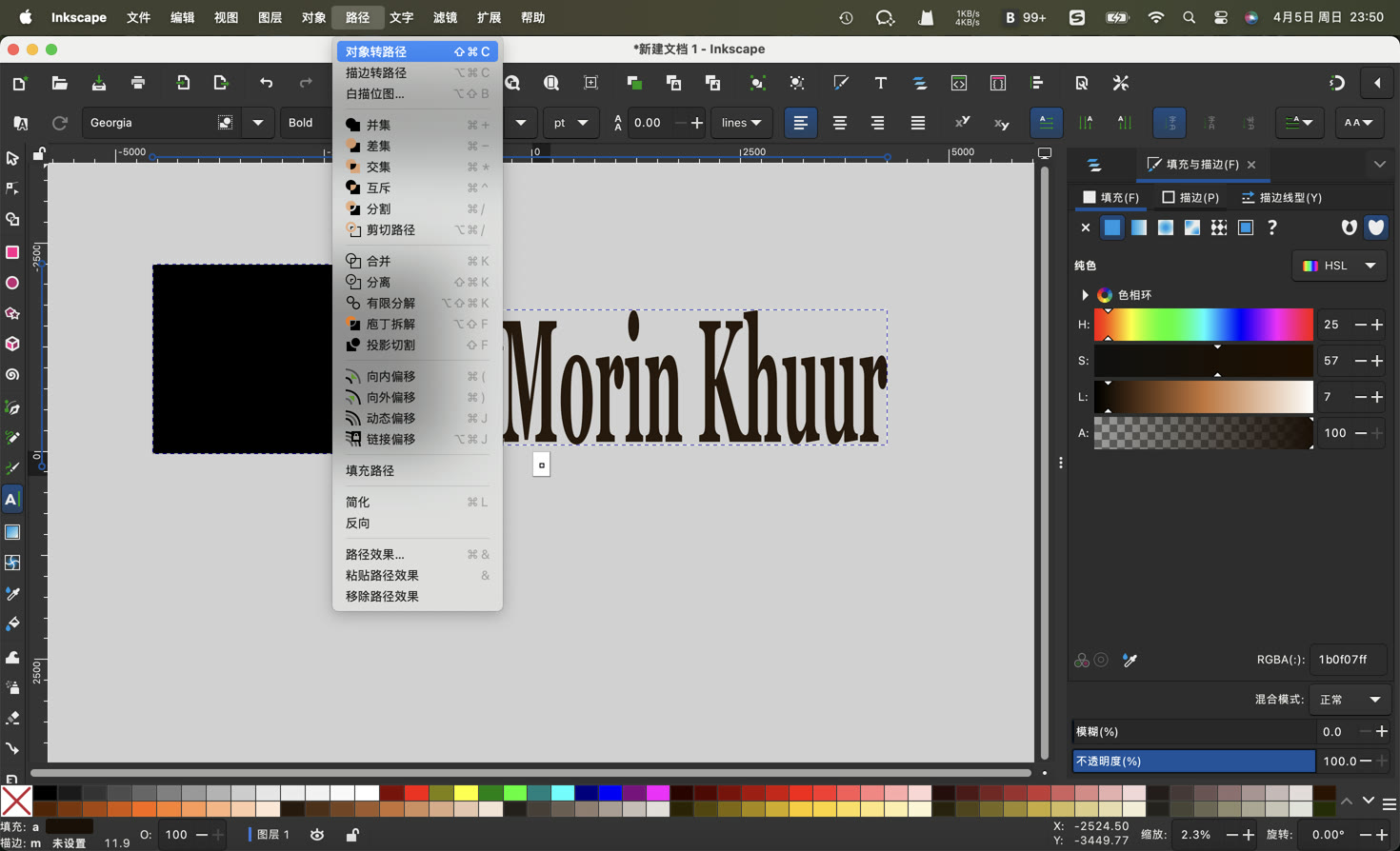
The most important step was using the Object to Path function. This converts editable fonts into mathematical lines that a laser cutter can recognize.
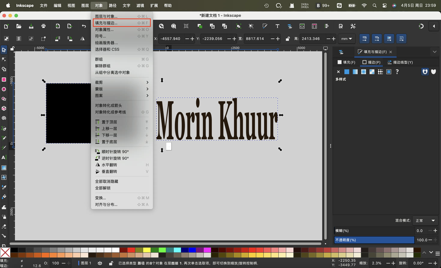
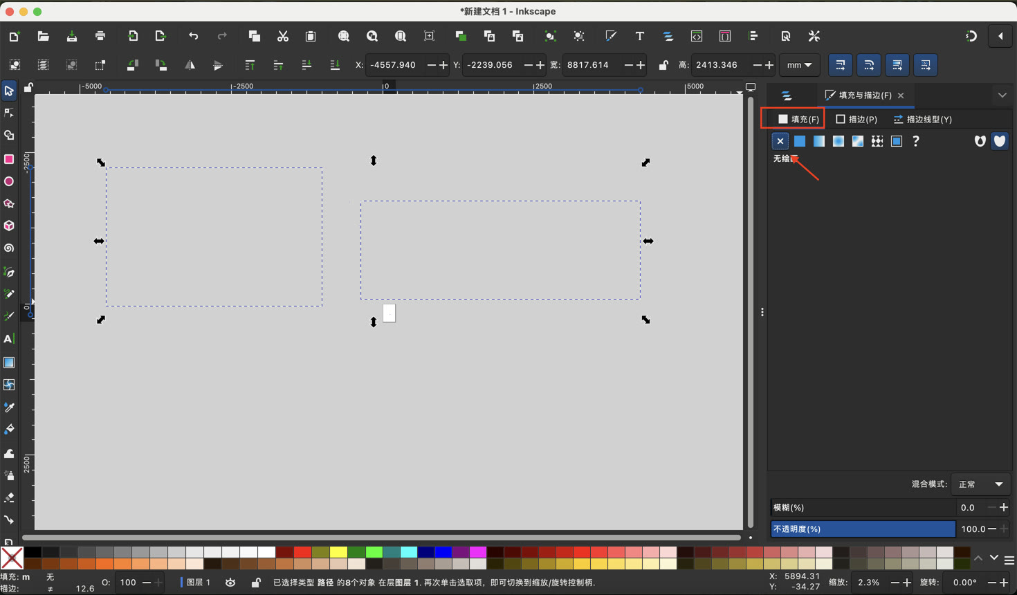
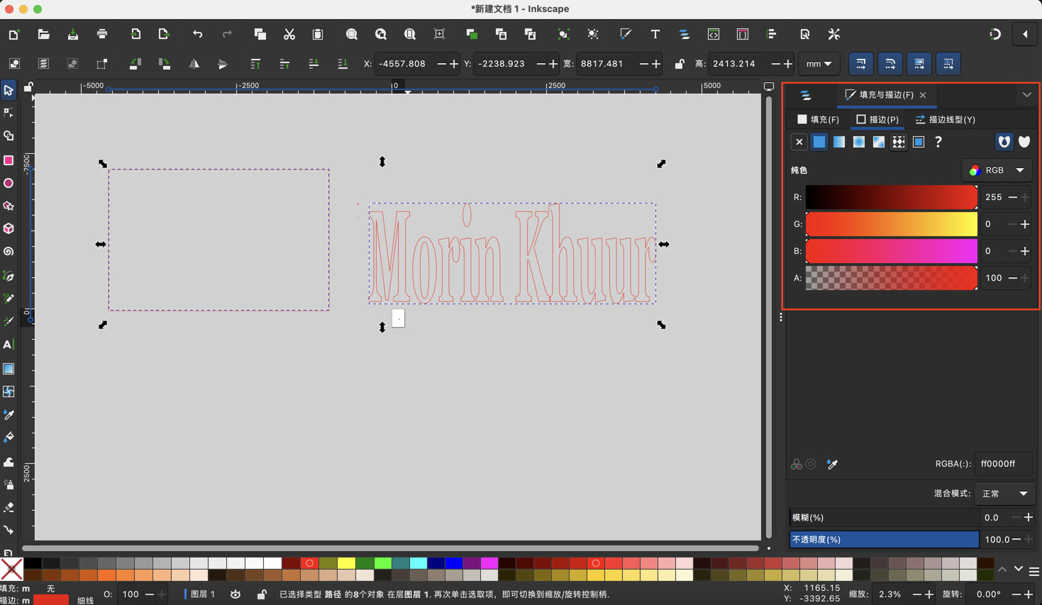
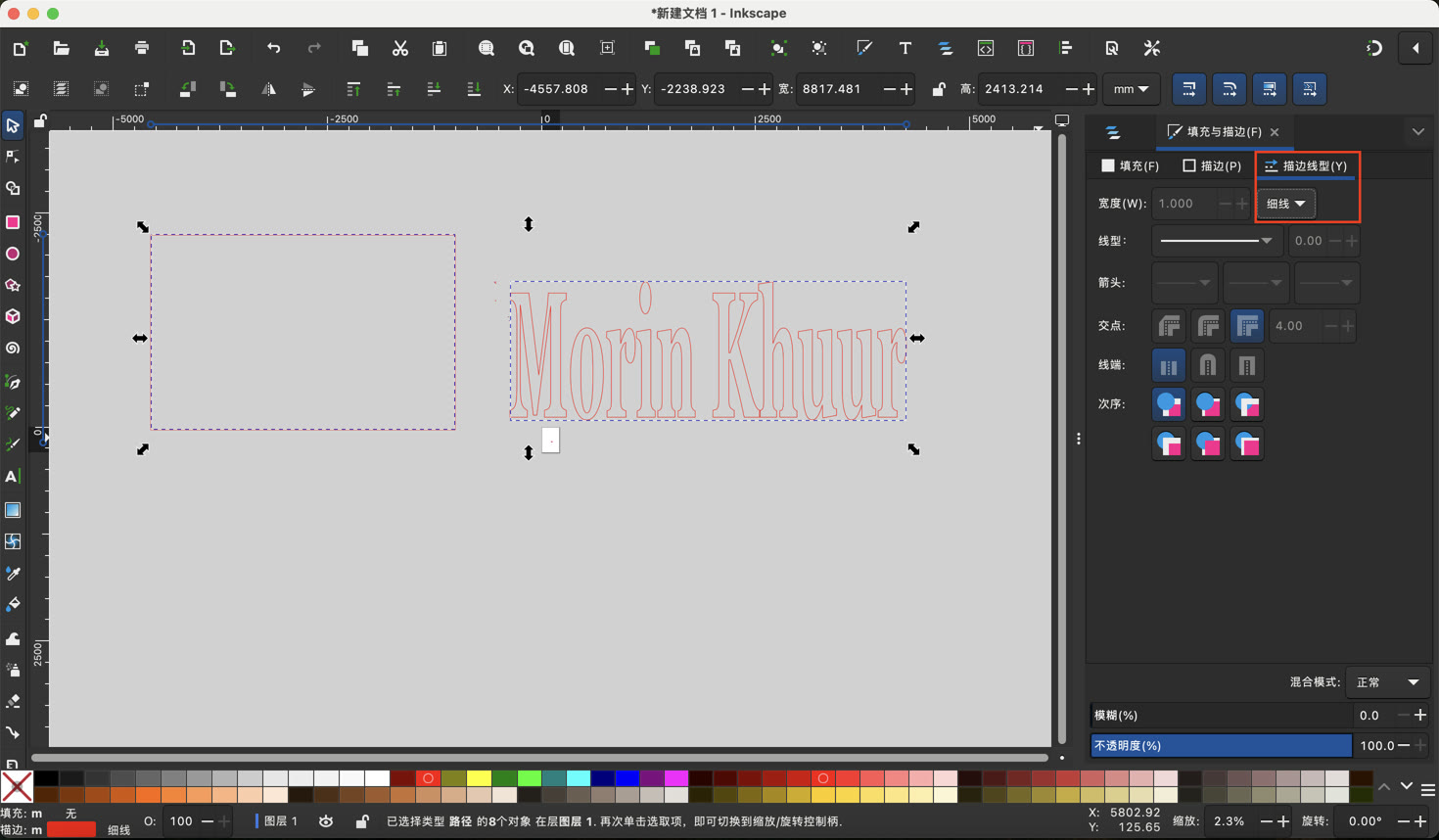
To prepare for future assignments, I adjusted the Fill and Stroke settings. I set the Fill to none and changed the Stroke paint to red (RGB: 255, 0, 0). I also set a very thin stroke width.
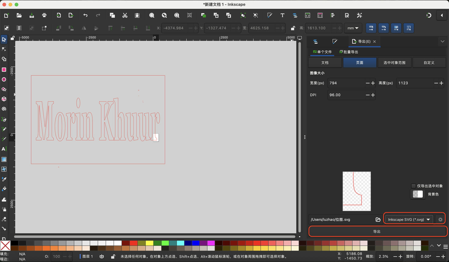
I saved the final design as a Plain SVG file.
4. Moving into 3D Design with Onshape
After completing the 2D assignments, the next challenge is 3D modeling. I have chosen to use Onshape, a professional-grade parametric CAD tool that runs in the browser. My goal is to transform 2D sketches into 3D volumes, which will be the foundation for my future 3D printing and CNC machining projects.
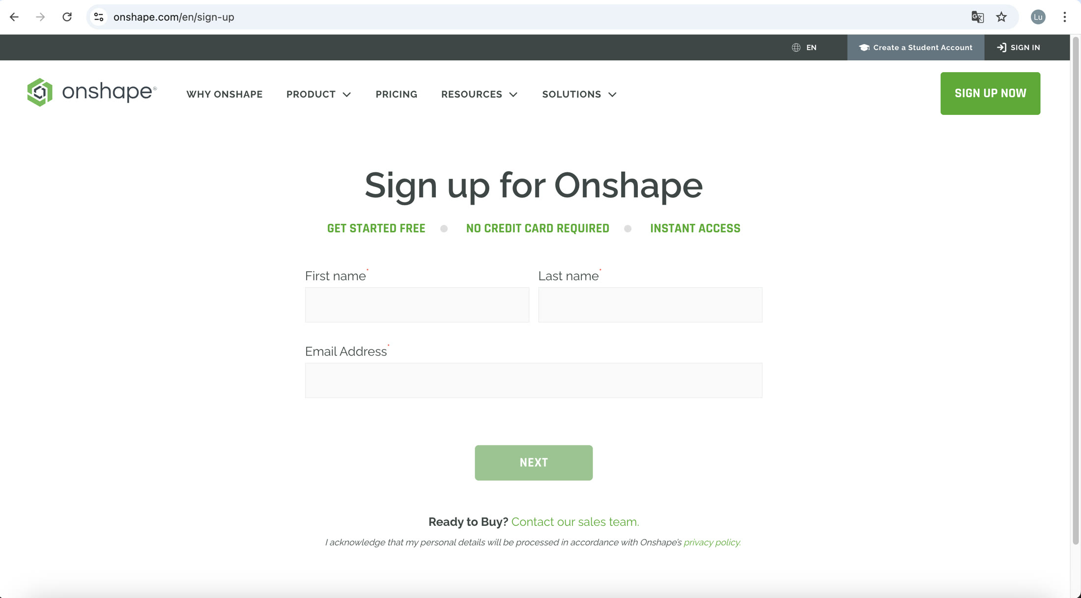
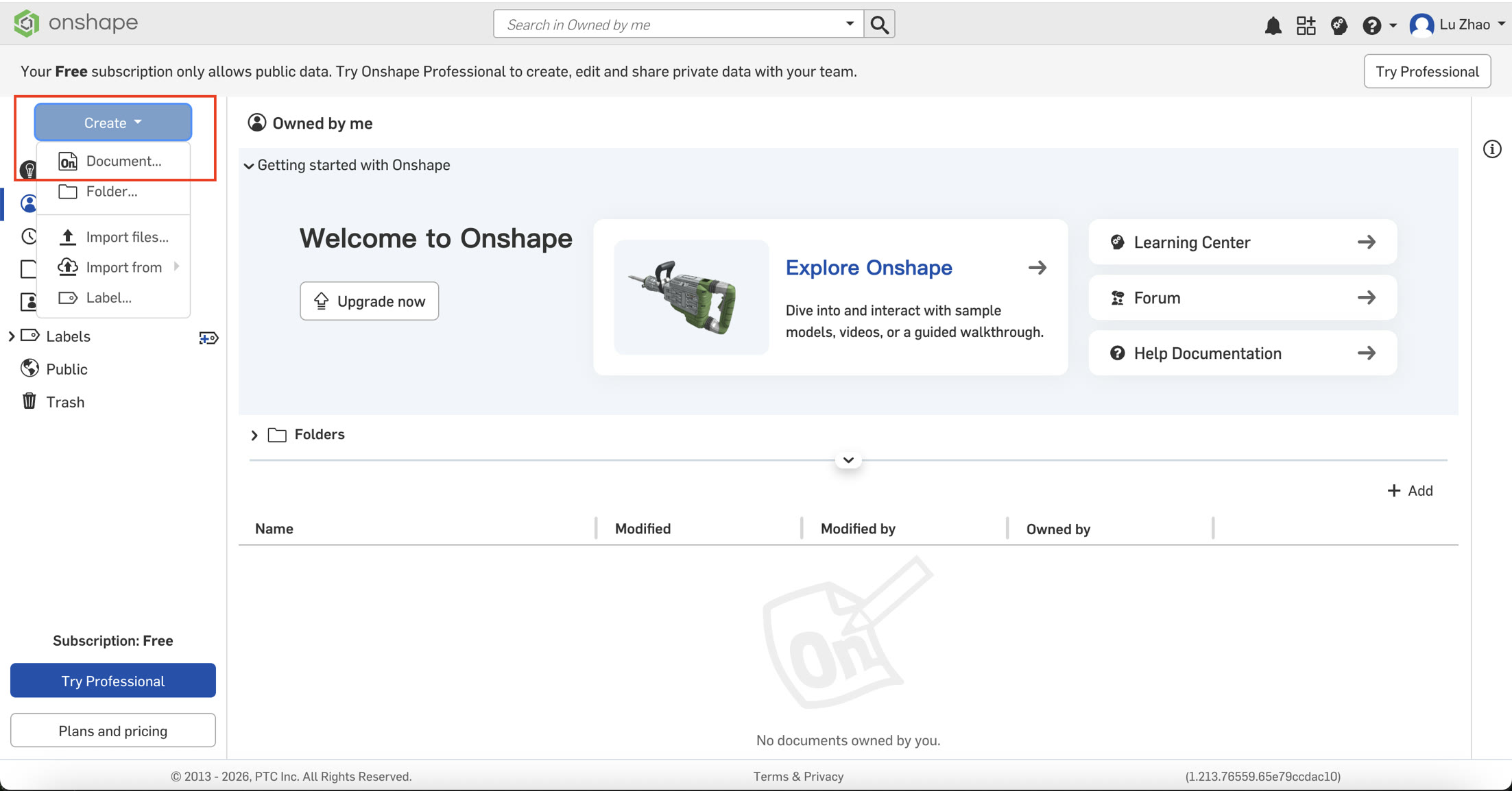
I started my first 3D work by creating a simple storage box. I went to the Onshape website to sign up first.
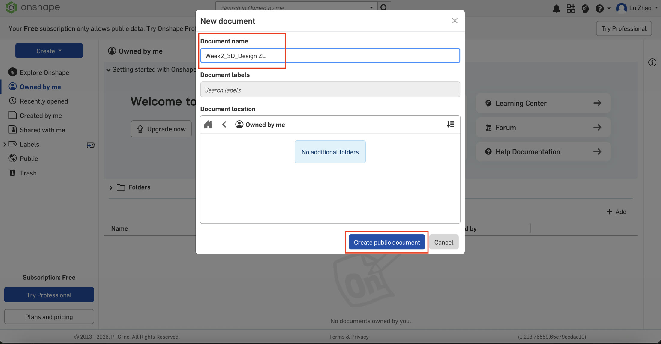
Then I created a new document and named it.
4.1 Step-by-Step Workflow
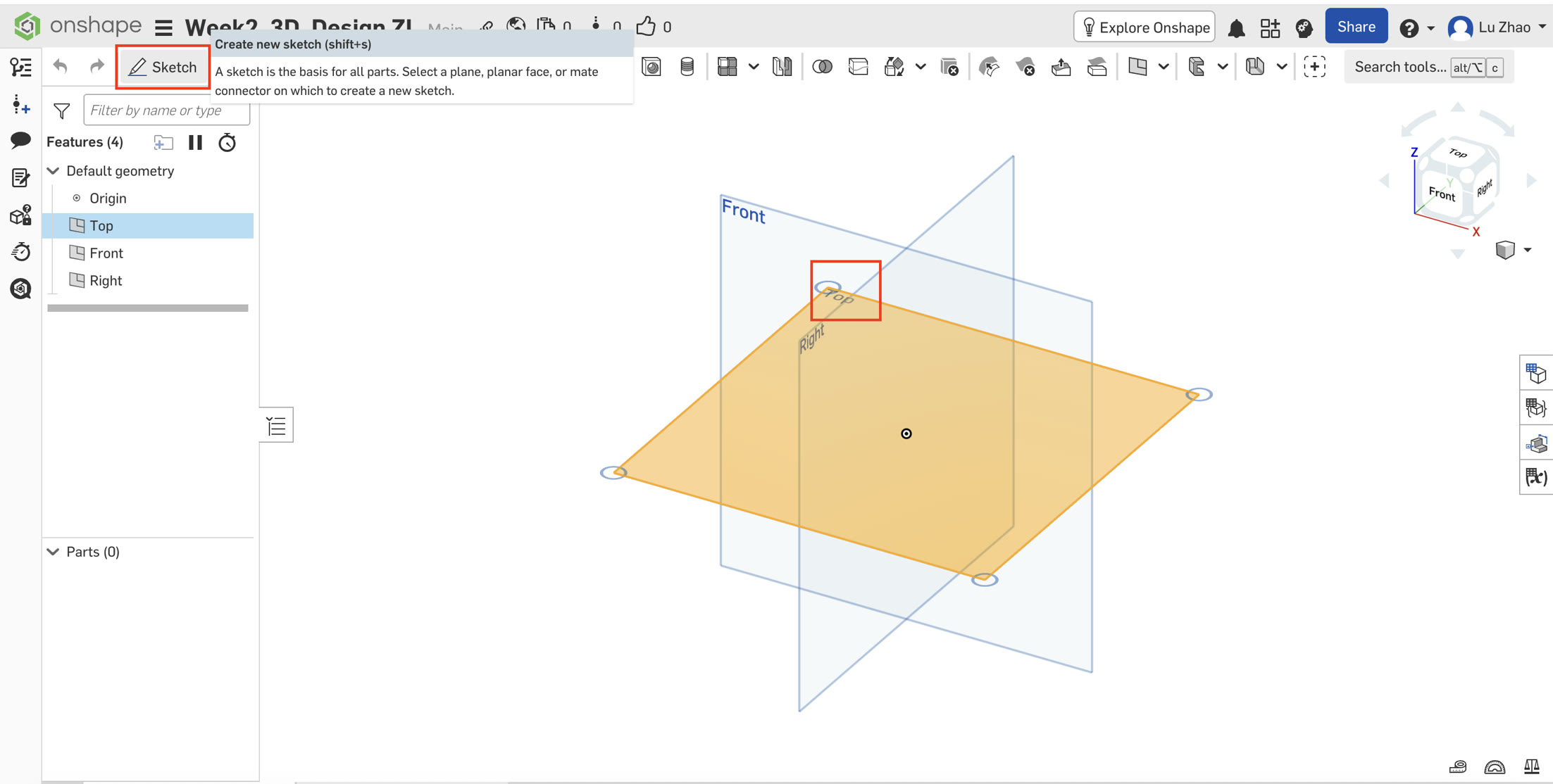
A. Creating the 2D Sketch
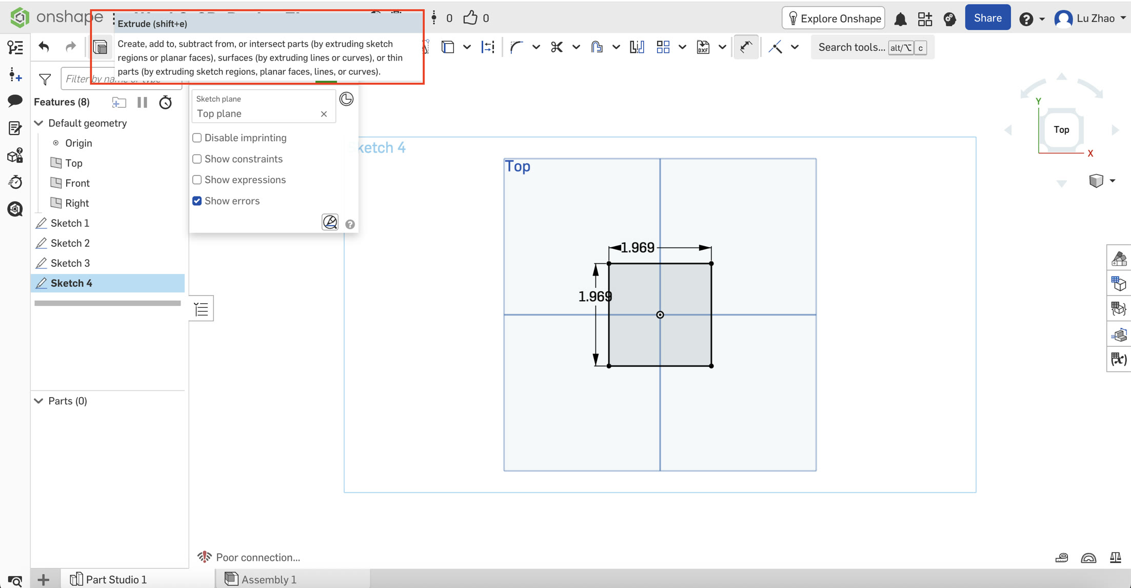
I started by selecting the Top Plane and entering the Sketch mode. I used the shortcut key "N" to directly view the top surface.
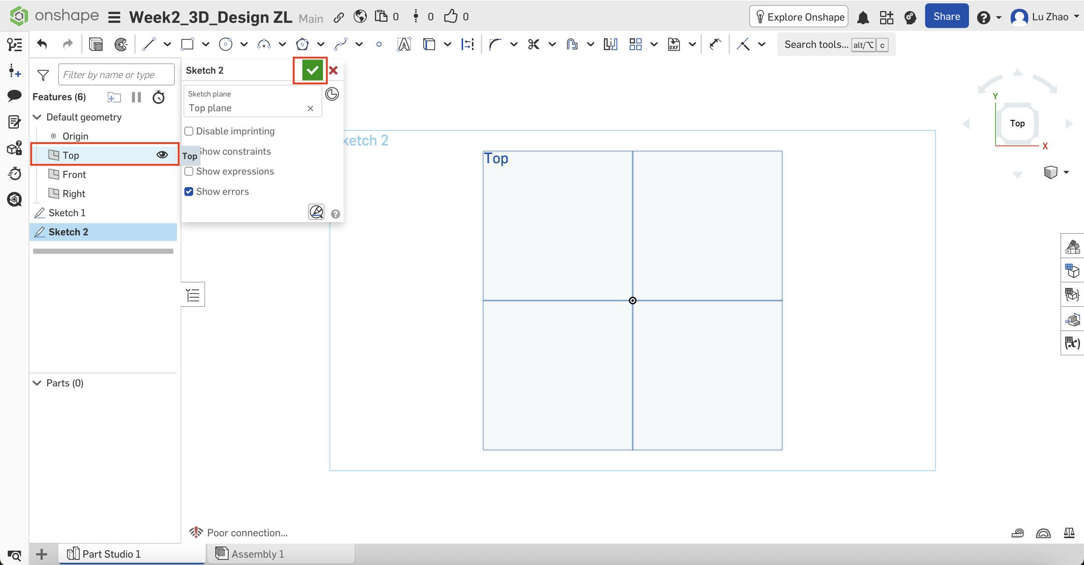
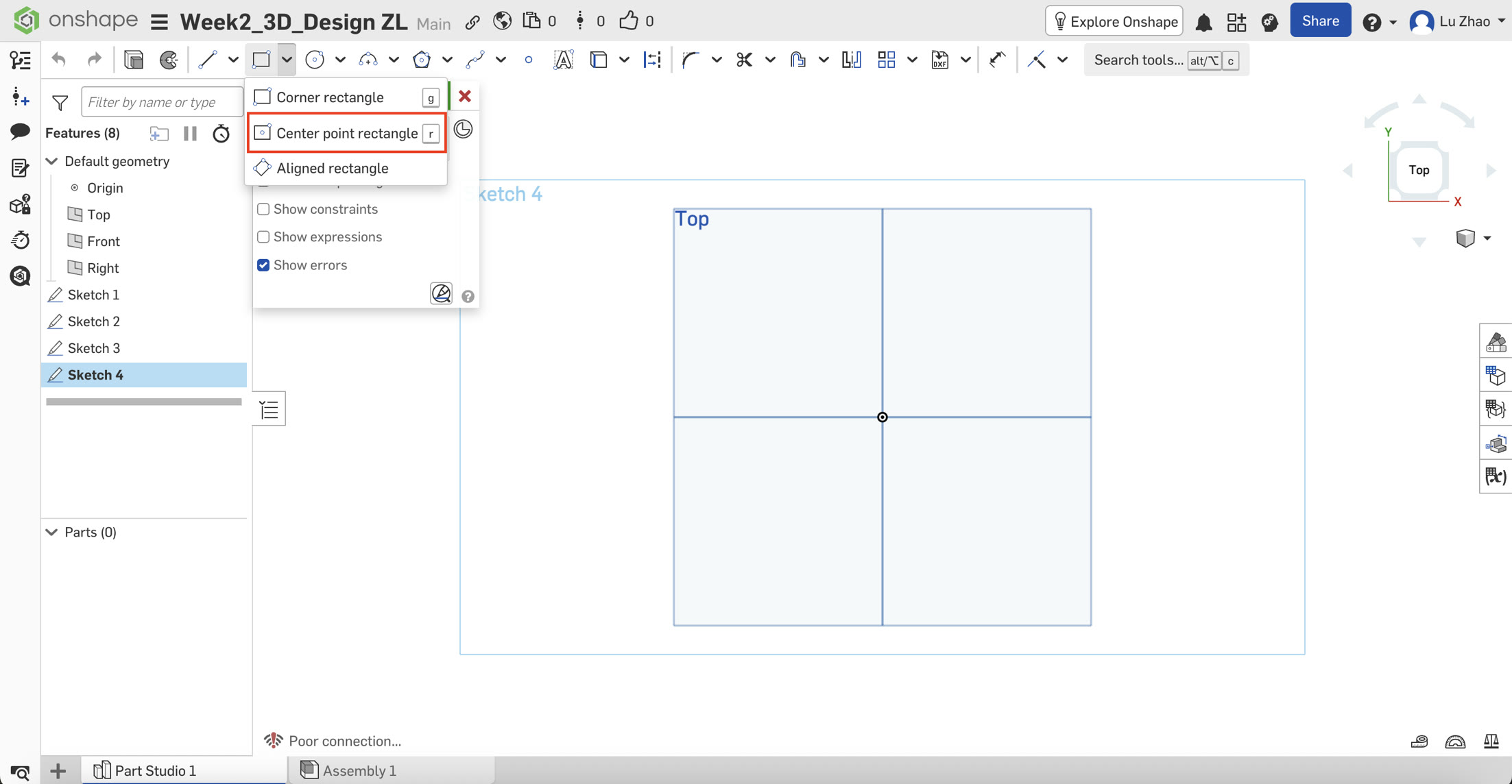
Find the Center point rectangle in the tool bar and create the rectangle.
- The Challenge: Initially, I struggled to find the Center Point Rectangle tool. After exploring the interface, I discovered it was hidden in the dropdown menu of the default rectangle tool.
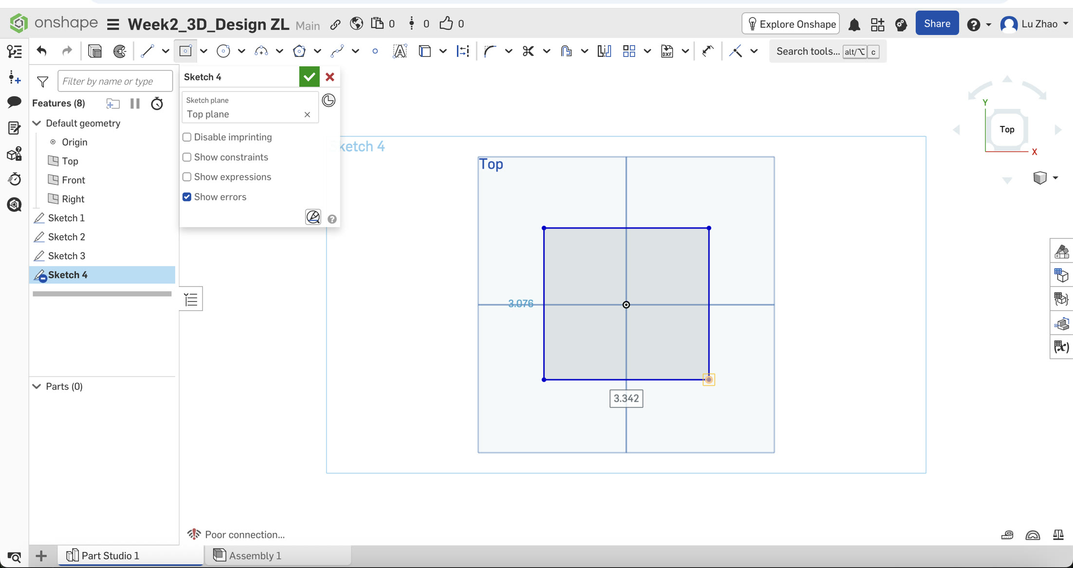
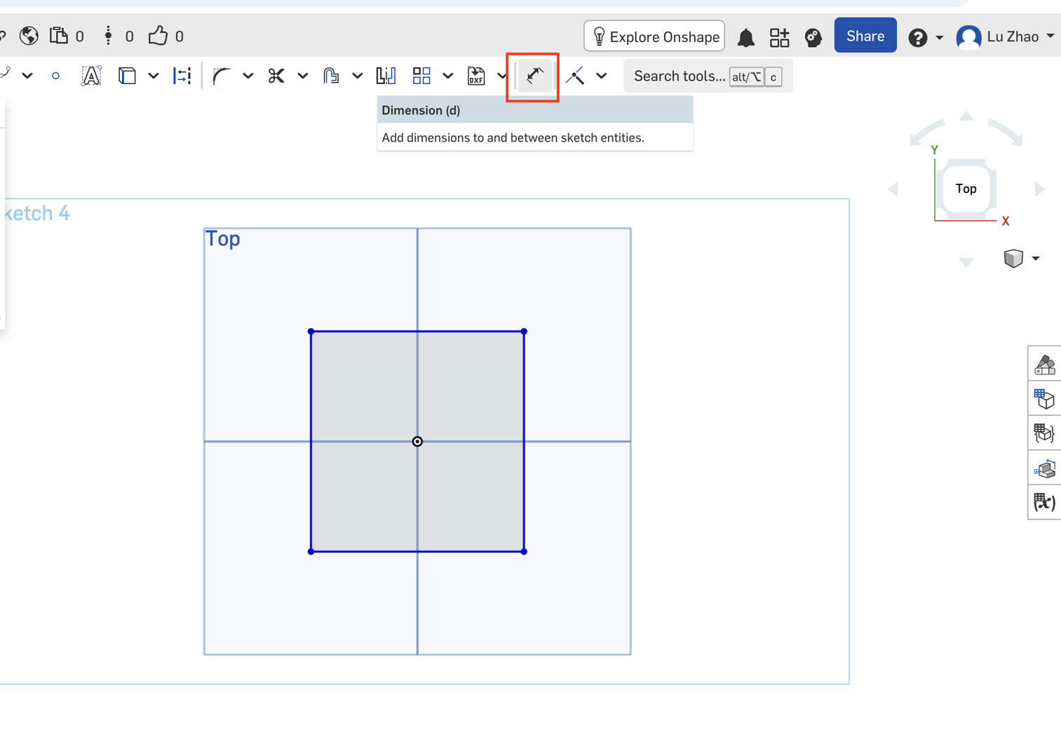
- Applying Dimensions: I used the Dimension Tool (D) to define the size. I encountered a slight hurdle here—the input box didn't appear immediately. I learned that I had to click the line, drag the mouse, and click again in the empty space to activate the input.
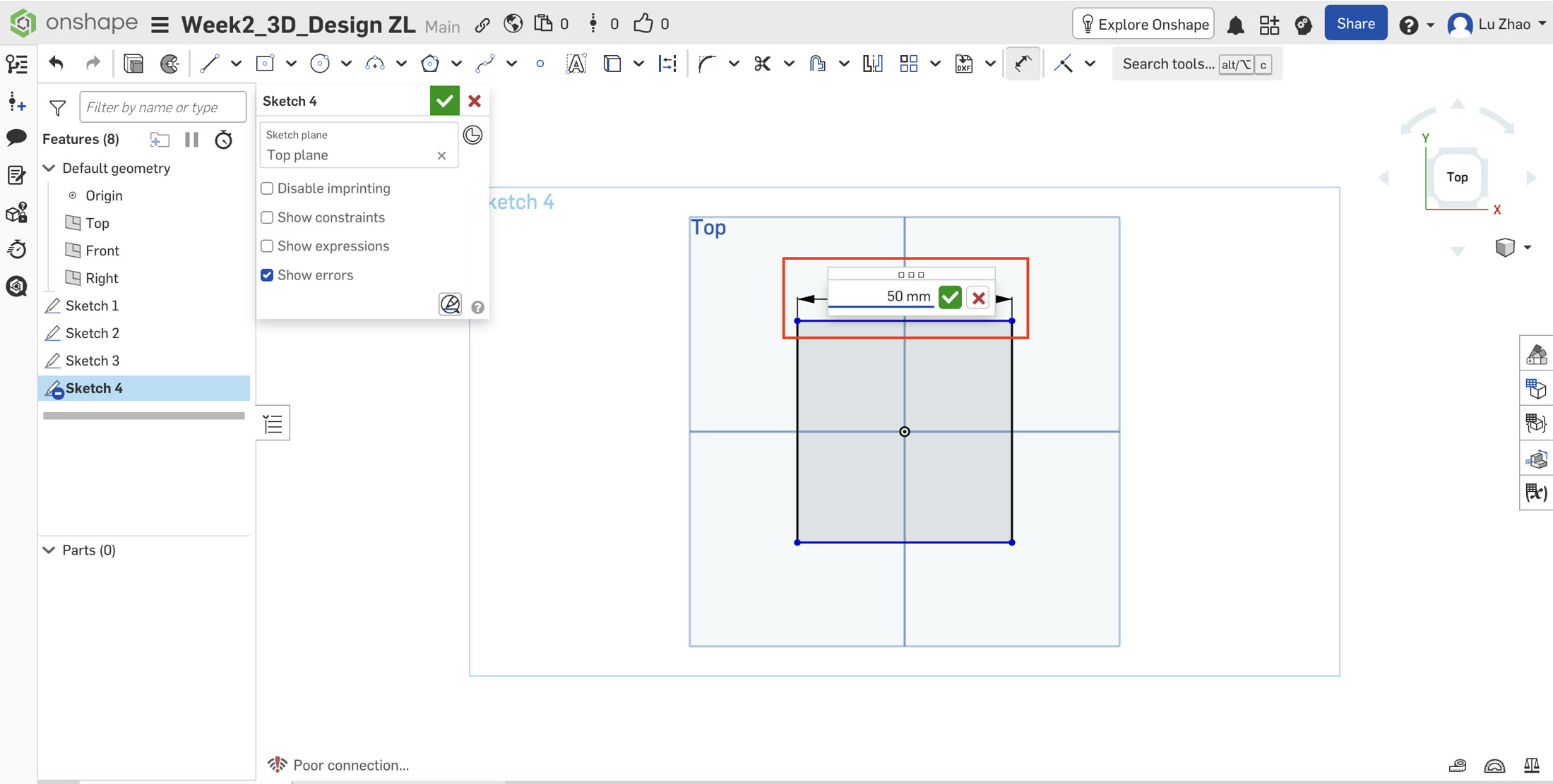
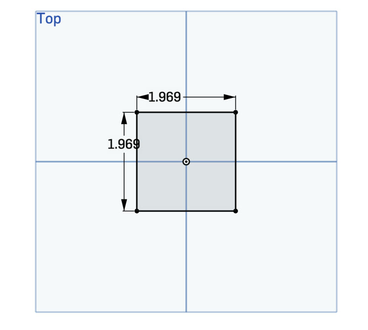
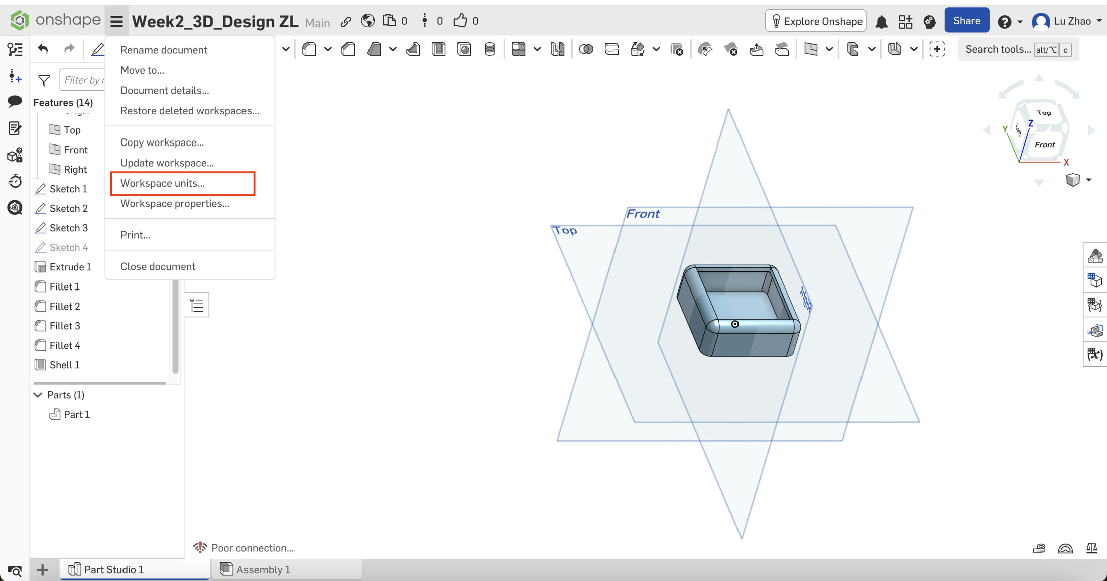
- The "Unit" Discovery: I typed "50 mm," but the software displayed "1.969." I realized the workspace was set to Inches. Instead of panic, I treated this as a learning moment: 1.969 inches equals 50 mm, it's not an error of my work. I later went into the Workspace Units menu and switched the default length to Millimeters for consistency at the end.
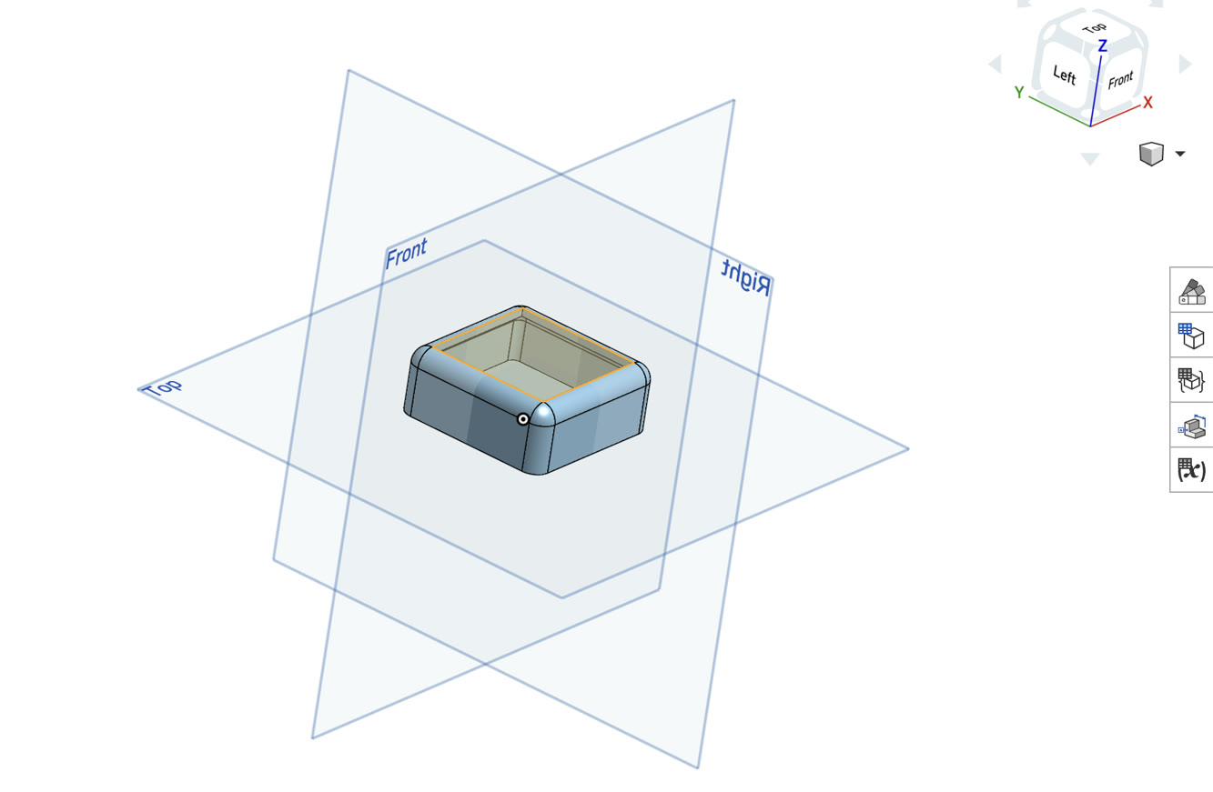
B. Transforming to 3D (Extrude)
Once the square was defined, I used the Extrude tool with a depth of 20 mm.
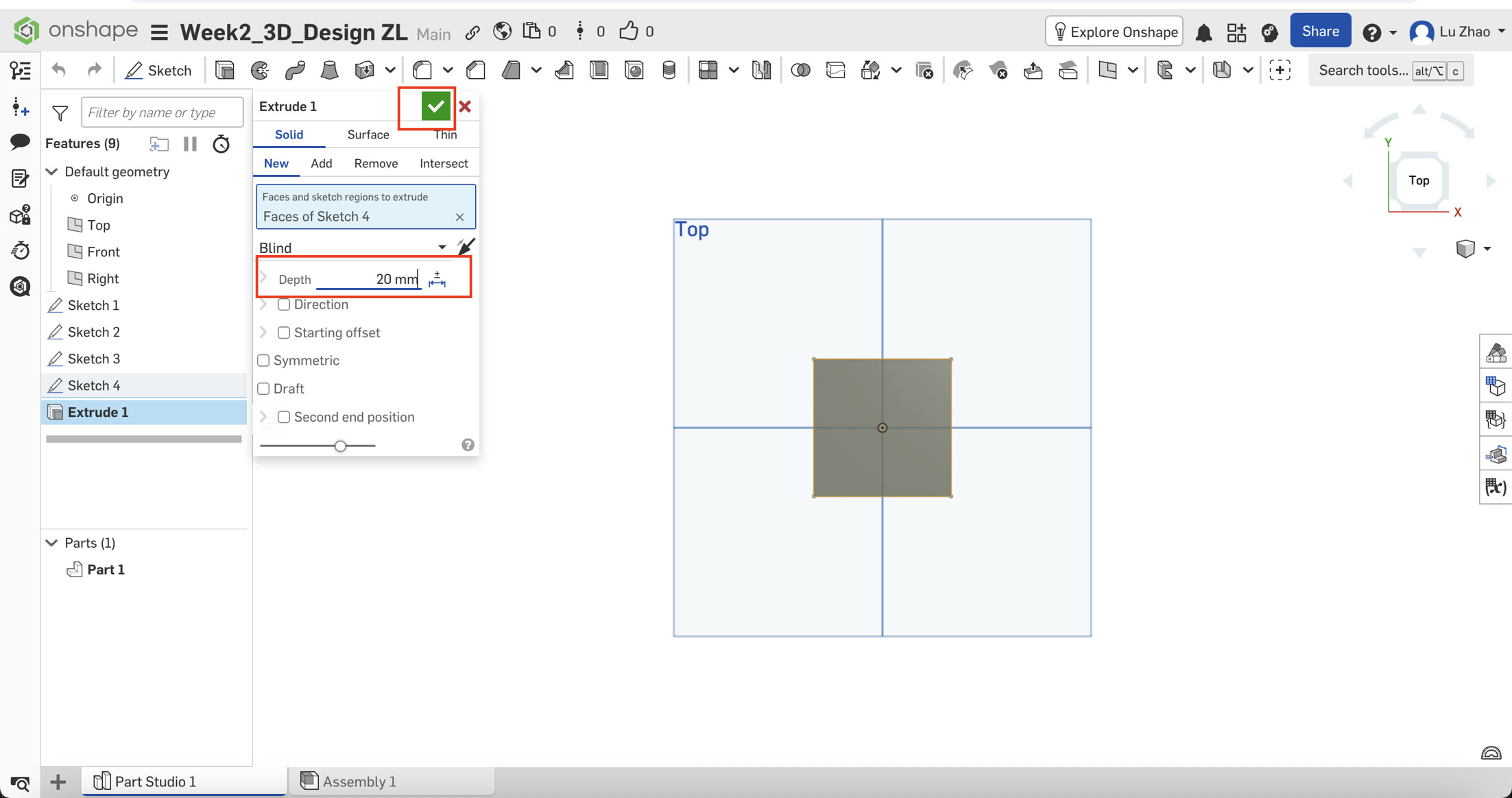
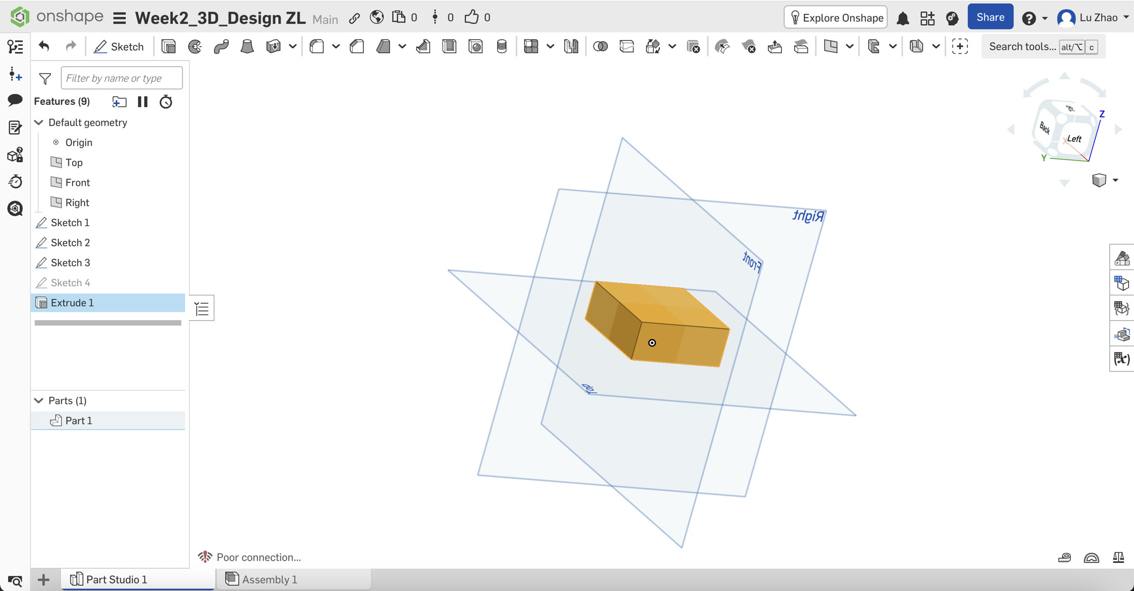
- Visual Confusion: After clicking the green checkmark, the model still looked like a flat square. I realized I was still in the "Top View." By holding down the mouse right button and slide, the model rotated into an Isometric view, revealing its 3D volume.
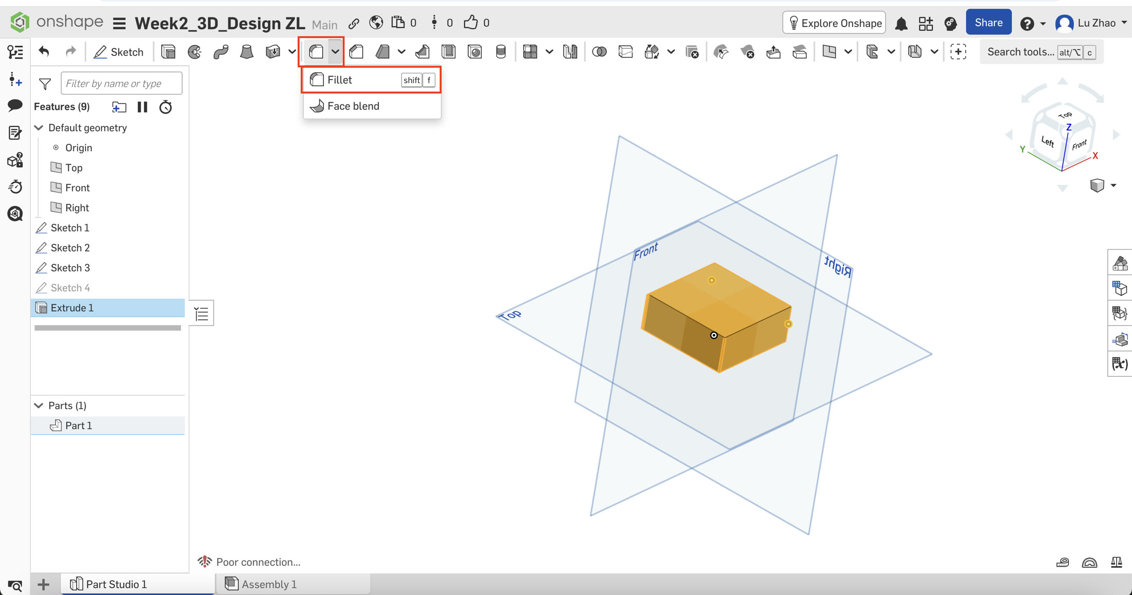
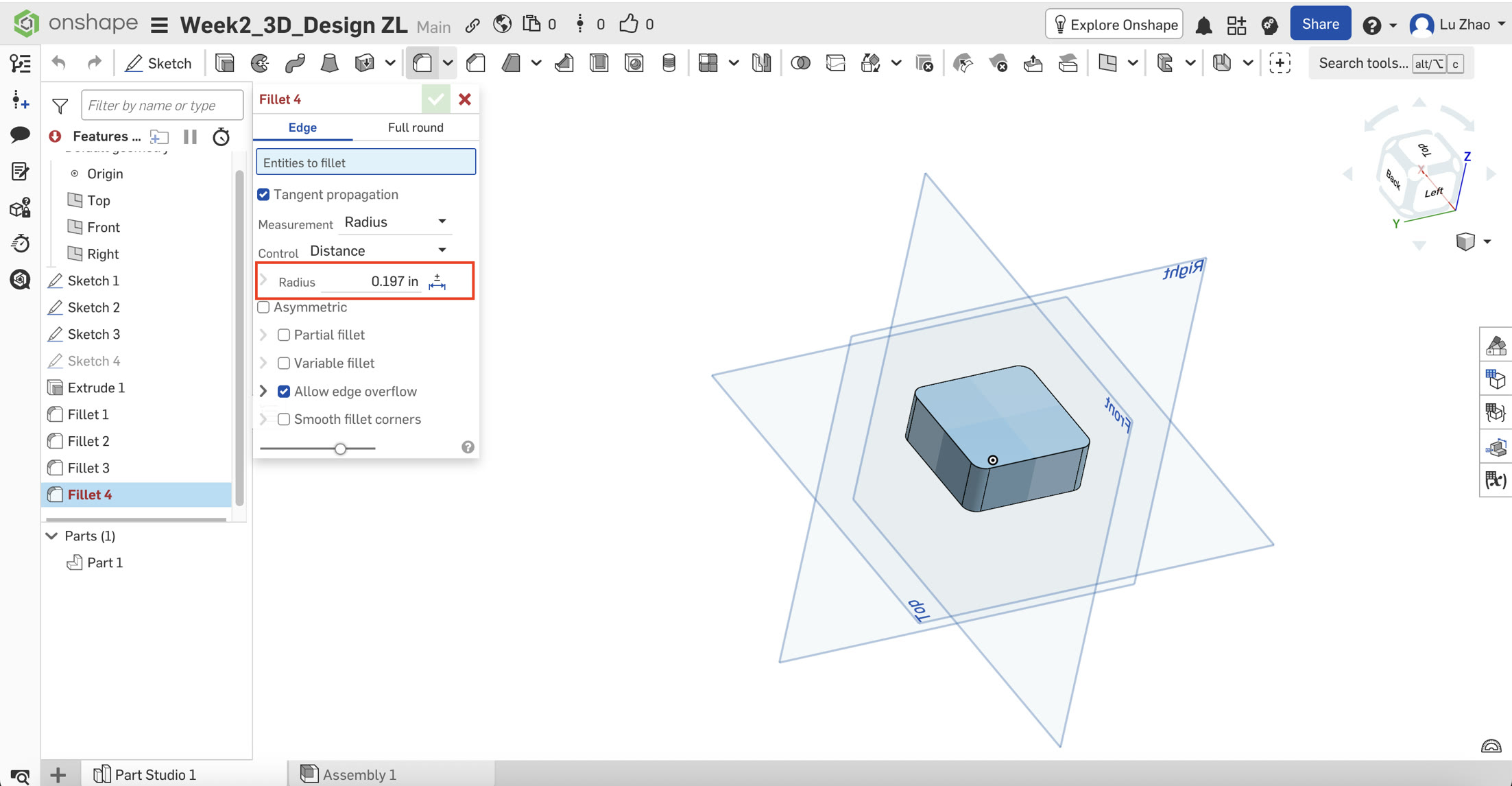
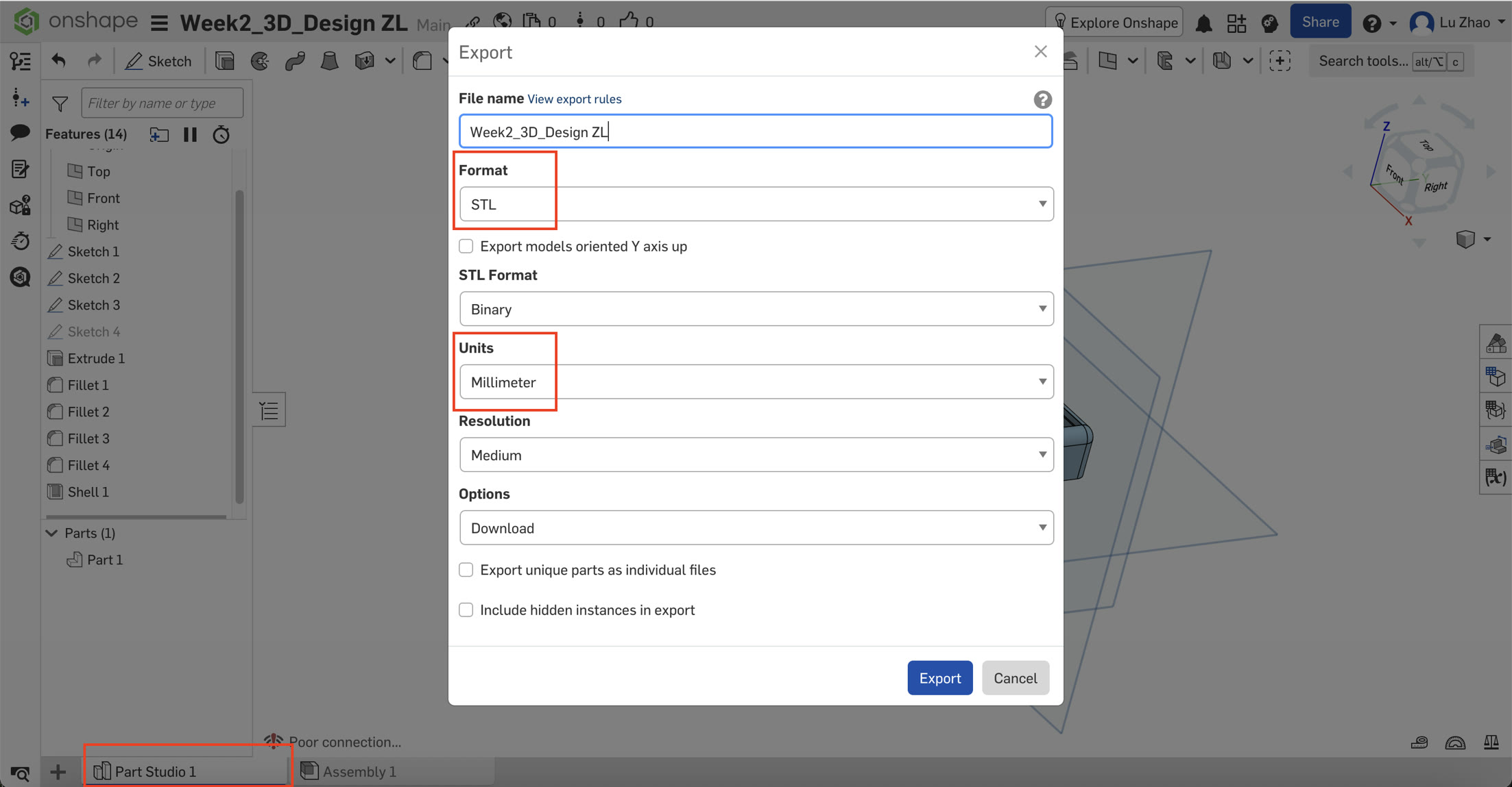
C. Adding Professional Touches (Fillet & Shell)
To make the model more functional, I applied two advanced features:
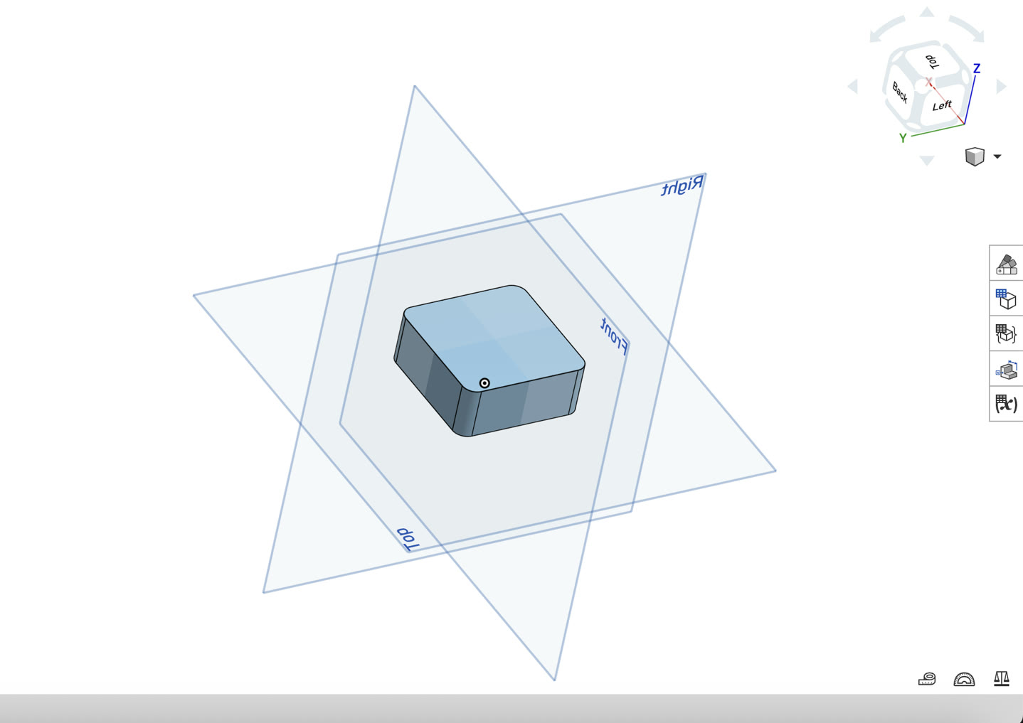
- Fillet: I selected the four vertical edges and applied a 5 mm (0.197 in) Fillet. This rounded the corners, giving it a sleek, industrial look.
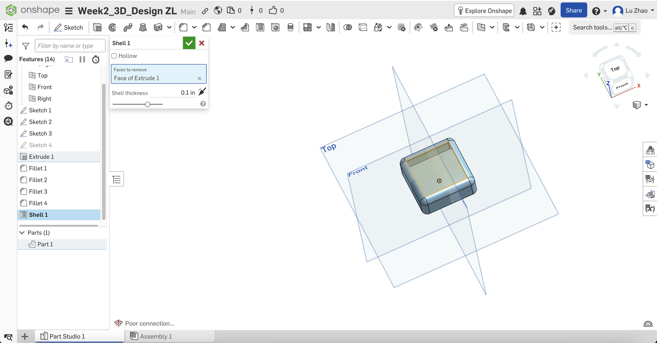
- Shell: This was the most impressive step. I selected the top face and applied the Shell tool. The solid block was instantly hollowed out, leaving a uniform wall thickness. This transformed the block into a functional enclosure base.
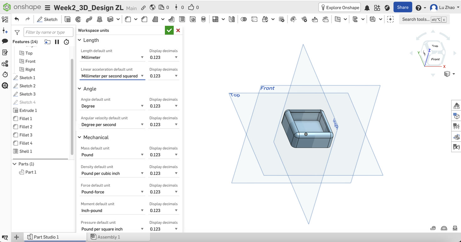
D. Export to STL file
Finally, I exported my 3D model in STL format, right click the "Part Studio 1" at the bottom left, and select "export". I ensured the units were set to Millimeters during export to maintain the correct scale for future 3D printing. Having a localized copy of my cloud-based design is essential for the next steps of physical fabrication.
Before exporting, I tried to change the dimension unit of size to millimeter, in "Workspace units".
4.2 Troubleshooting & Reflections
As a beginner, this exercise taught me that CAD is not just about drawing, but about defining relationships and units.
- Real-world problem solving: Dealing with the unit conversion (mm to inches) and navigating the nested UI menus helped me understand the logic of professional engineering software.
- Efficiency: By choosing a parametric tool like Onshape, I can now easily go back to my initial sketch, change the "50mm" to "60mm," and the entire 3D box—including the fillets and the shell—will update automatically. This efficiency is vital for my goal of completing Fab Academy on time.
5. Final Reflections on Week 2
This week was a steep learning curve but highly rewarding. By exploring Photopea (Raster), Inkscape (Vector), and Onshape (3D Parametric), I now have a solid foundation for digital fabrication. I've learned that choosing the right tool for the specific task—whether it's web optimization or mechanical design—is the key to an efficient workflow.