Week 10 - Output Devices
Group Assignment
The link to our group work: https://fabacademy.org/2026/labs/chaihuo/docs/week10/chaihuo/week10_group_assignment
For this week's group assignment, we focused on measuring the actual power consumption of output devices on our custom PCBs using a multimeter.
Coming into this program with very little background in electronics, terms like "Voltage," "Current," and "Power" used to just blur together for me. This week’s group exercise was valuable because it forced me to stop looking at code and physically probe the hardware. It was a massive reality check. Here is my detailed breakdown of what finally clicked for me:
Voltage vs. Current: The "Water" Analogy
During the group test, I finally understood the physical difference between what we were measuring.
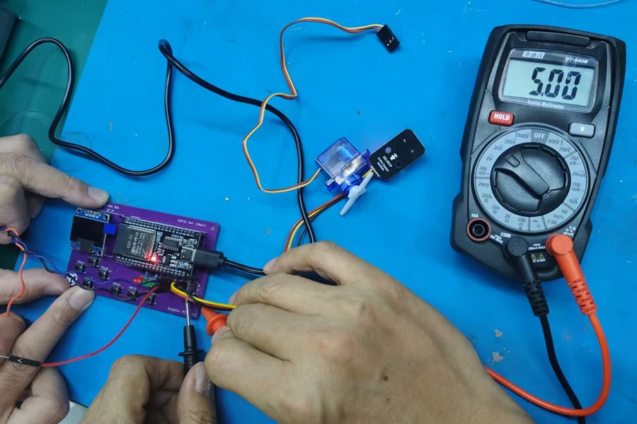
Voltage (V): I learned to think of voltage like water pressure. To measure it, we don't need to interrupt anything. we just take the multimeter probes and touch two points (like VCC and GND) in parallel. Our board read exactly 5.00V. It’s like checking the pressure difference between the top and bottom of a waterfall.
Current (I): This is the actual volume of water flowing through the pipe. This was the scary part for me. To measure current, I learned that I cannot just poke the board. I have to literally break the circuit and insert the multimeter in series. The electricity must flow through the meter to be counted.
The Danger of Measuring Current
Our group instructor heavily emphasized safety here. If we accidentally leave the multimeter leads in the "Amp" (Current) ports and try to measure voltage across the power and ground rails, we will create a massive short circuit and instantly blow the fuse inside the multimeter. Learning this physical distinction made me much more cautious and deliberate when handling my custom PCBs.
Calculating Power** ($P = V \times I$)**
Once we safely measured both values on a basic GPIO pin driving a tiny load, we got 5.00V and 2.78mA (which is 0.00278 Amps). The formula for Power is P = V × I. So, P = 5.00 V × 0.00278 A = 0.0139 W (or 13.9 mW). This taught me that a logic-level signal uses almost no real power—it's just whispering instructions, not doing heavy lifting. But this immediately got me thinking about my own final project.
2605 Update: How this informed my Final Project (Theory vs. Reality)
This group assignment completely changed how I look at my electro-acoustic Morin Khuur's hardware. My output device is a massive 160-LED WS2812 strip used for the audio visualizer.
Sitting in the lab, I applied the same power formula to my components and got a terrifying number:
If a single WS2812 LED draws roughly 60mA at full white brightness, then 160 LEDs could theoretically draw up to 9.6 Amps! (160 × 60 mA = 9.6 A).
This confused me at first, because during my early prototyping, I had successfully powered the whole LED strip directly from my computer's USB port without causing a fire. How was that possible if my laptop USB only provides around 1 Amp?
After diving deeper into the physics, I realized that 9.6A is the "worst-case scenario" (all 160 LEDs stuck on 100% pure white). Because my project is a dynamic audio visualizer, the LEDs are constantly shifting colors and turning on and off to the music. A red pixel might only draw 20mA, and a black pixel draws almost nothing. The average dynamic current was actually low enough for the USB to survive.
However, relying on this "average" is terrible engineering. If my software ever crashed and locked all 160 LEDs to pure white, it would instantly try to pull massive current and destroy my ESP32 microcontroller or my computer's USB port.
Because of this week's power measurement exercise, I learned the critical difference between Theoretical Peak Power and Dynamic Power. I realized I must design a completely separate power routing system: the ESP32 will only send the lightweight digital data signal, but the actual 5V power for the LEDs must be wired directly from a dedicated, high-current battery source, completely bypassing the fragile microcontroller.
Individual Assignment
Overview
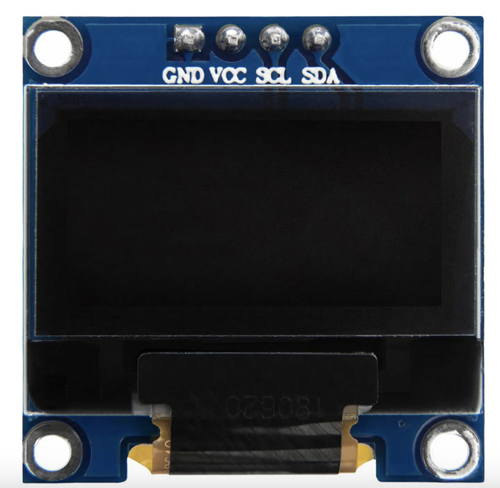
For this week's assignment, I integrated an I2C OLED (Organic Light Emitting Diode) display into my custom-designed XIAO ESP32C3 PCB. An OLED is a sophisticated output device that allows for high-contrast visual communication, capable of displaying text, numbers, and graphics.
Why I2C?
I chose the I2C (Inter-Integrated Circuit) version of the SSD1306 OLED. It is ideal for beginners and compact designs because it only requires two signal wires (SDA and SCL) to communicate with the microcontroller, regardless of how complex the visuals are.
Hardware Components & Logic
The Output Device: 0.96" SSD1306 OLED
-
Resolution: 128 x 64 pixels.
-
Communication Protocol: I2C.
-
Voltage: 3.3V (perfect for ESP32 logic levels).
Features:
OLED self-luminous, no backlight
Size: 0.96”
Driver IC: SSD1306
Voltage: 3.3V-5V DC
Viewing angle: > 160°
High resolution: 128 x 64
Working Temperature: -30°C~70°C
Display: 2 rows of yellow, 6 rows of blue
Module Size: 27mmx 27mm x 4mm
Screen material: glass, need good protection
I2C Interface:
GND: Ground
VCC: 3.3V~5V
SCL: I2C Serial Clock (UNO: A5; MEGA: 21)
SDA: I2C Serial Data (UNO: A4; MEGA: 20)
The Logic Path
-
Input: The code stored in the ESP32C3.
-
Processing: The ESP32C3 processes the data and sends it via the I2C bus.
-
Output: The SSD1306 driver chip receives the data and lights up specific pixels on the screen.
Hardware Connection (Pinout)
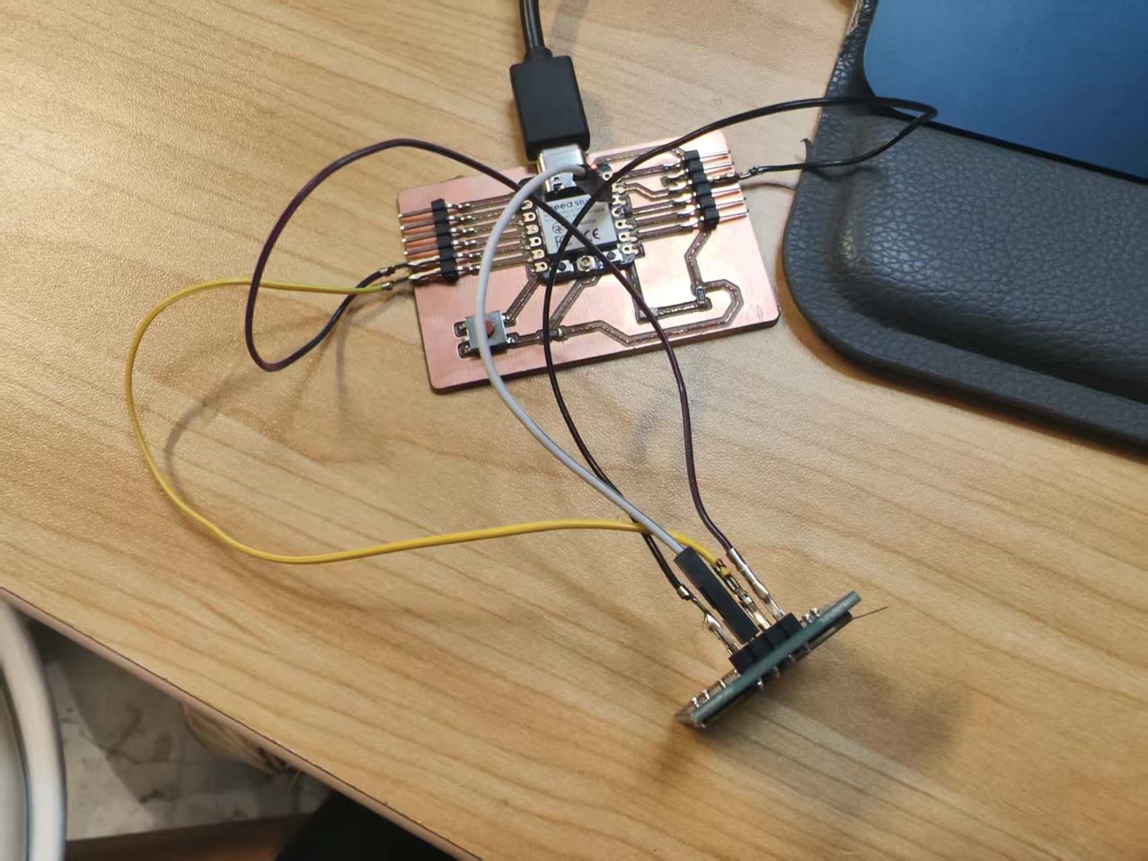
I used jumper wires to connect the OLED module to the headers I previously exposed on my custom PCB.
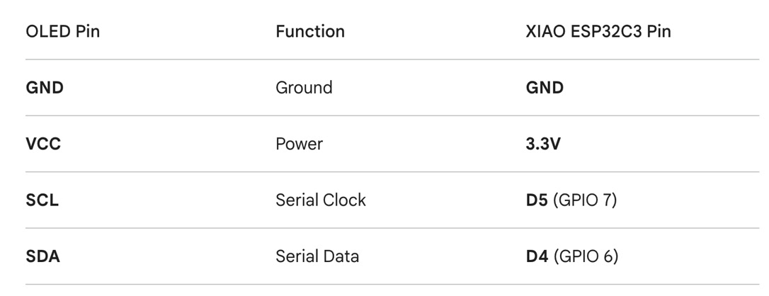
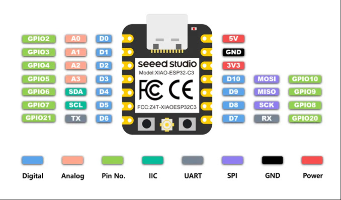
Before Wiring, I reviewed the pin definition of my designed board with XIAO ESP32C3 again as well as the 0.96" SSD1306 OLED.
I did the wiring accordingly, using the jumper wires.
Software Setup
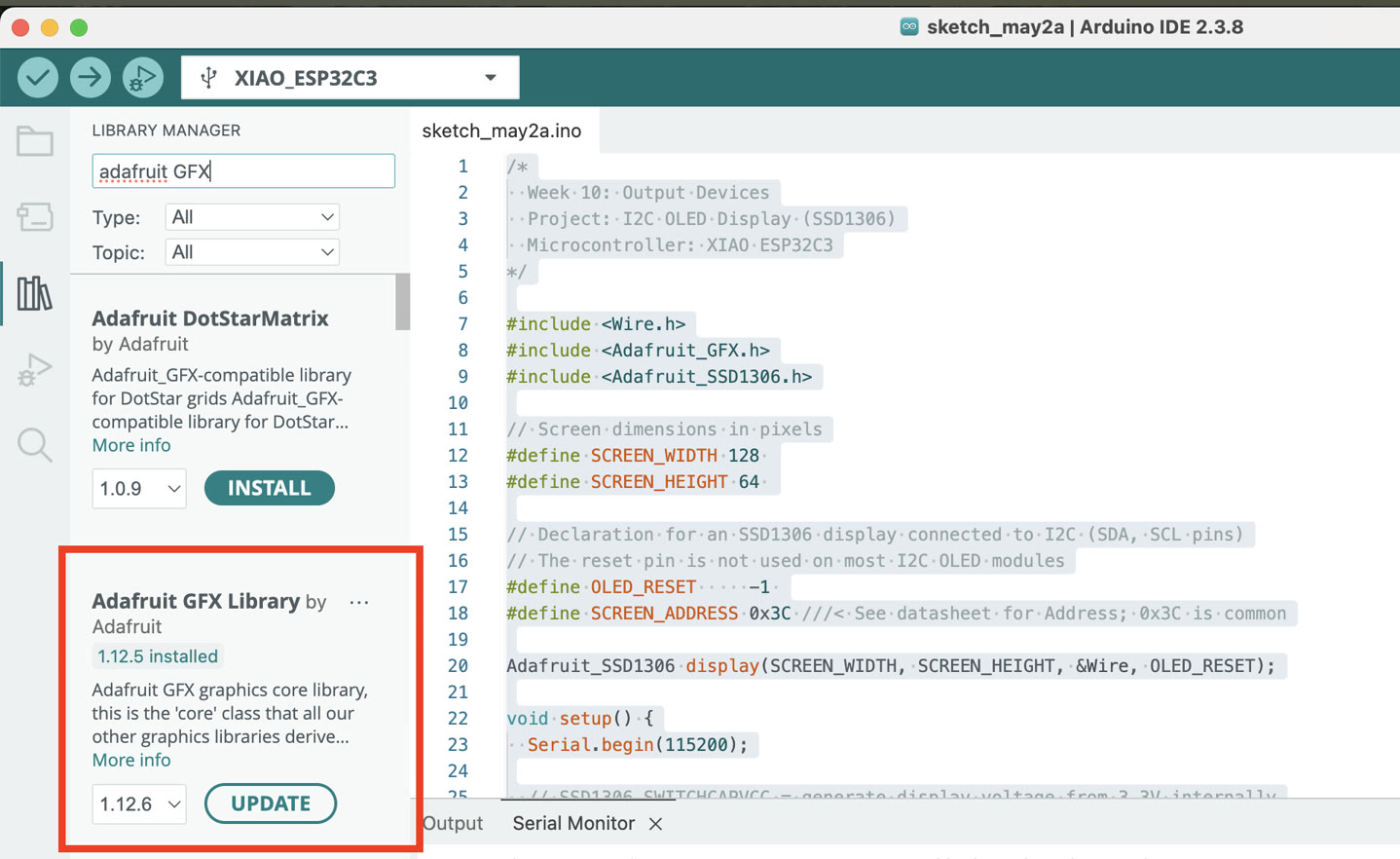
Installing Libraries
To control the pixels easily, I used two libraries from Adafruit. In the Arduino IDE:
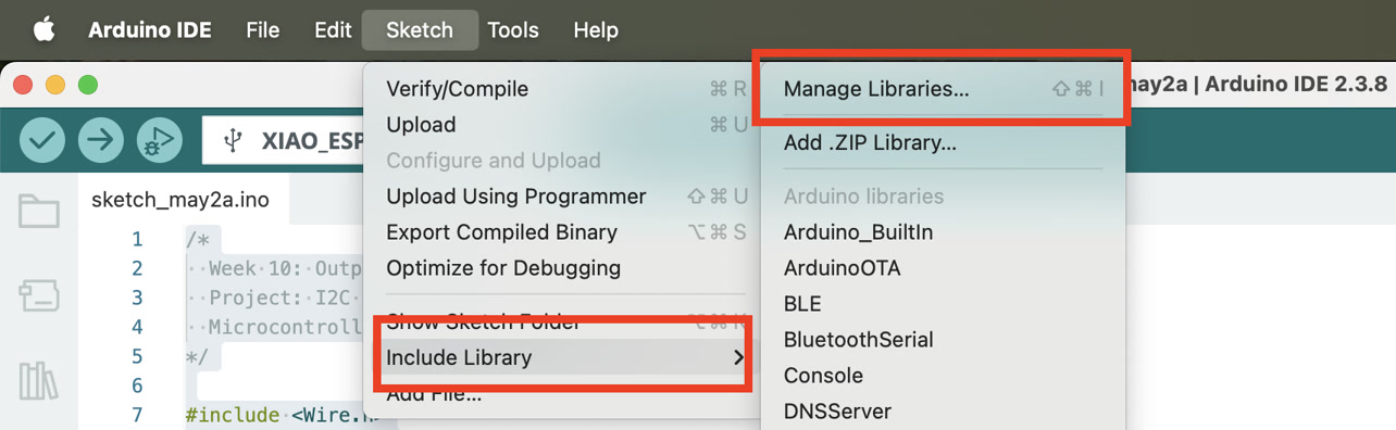
- Go to Sketch -> Include Library -> Manage Libraries...
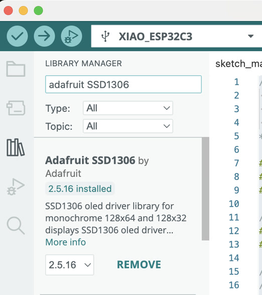
- Search for "Adafruit SSD1306" and install it.
- Search for "Adafruit GFX" and install it. (Select "Install All" to include all dependencies).
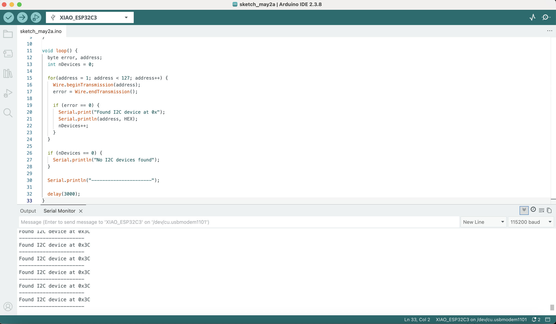
I2C Device Scan
Now I verify that the sensor is visible on the I2C bus. The code is generated by ChatGPT:
#include <Wire.h>

void setup() {
  Wire.begin();
  Serial.begin(115200);
  delay(1000);

  Serial.println("I2C Scanner Start");
}

void loop() {
  byte error, address;
  int nDevices = 0;

  for(address = 1; address < 127; address++) {
    Wire.beginTransmission(address);
    error = Wire.endTransmission();

    if (error == 0) {
      Serial.print("Found I2C device at 0x");
      Serial.println(address, HEX);
      nDevices++;
    }
  }

  if (nDevices == 0) {
    Serial.println("No I2C devices found");
  }

  Serial.println("----------------------");

  delay(3000);
}
Then this I2C OLED module is detected at the address of 0x3C. I can see the result from the Serial Monitor.
The Code
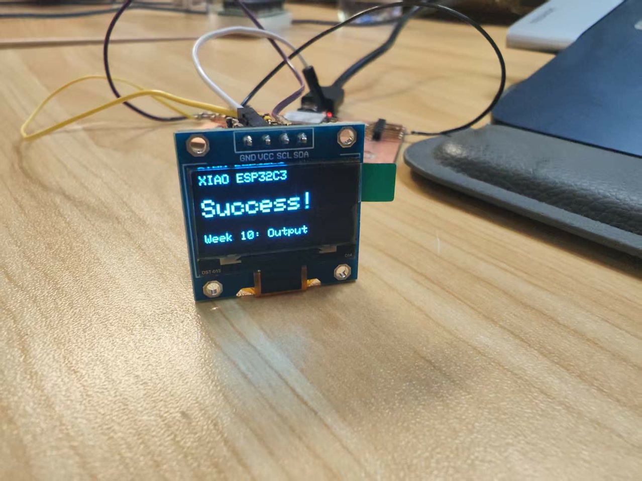
This script initializes the screen and displays a structured message. I asked Google Gemini to write a code.
The information shown on the OLED screen serves as a functional test to verify the precision of the coordinate system and text rendering:
- Header ("XIAO ESP32C3"):
Located at (0, 0) this identifies the controller. It uses Text Size 1 to maintain a clean, professional look at the top of the screen.
- Status Message ("Success!"):
This is the most important part of the test. I set the font to Text Size 2 and positioned it at (0, 20) to make it bold and centered. Seeing this specific word confirms that the SSD1306 allocation was successful and the data buffer is refreshing correctly.
- Assignment Label ("Week 10: Output"):
Located at the bottom (0, 50) in Text Size 1, this labels the project for the current Fab Academy module.
/*
  Fab Academy Week 10: Output Devices
  Device: 0.96-inch SSD1306 OLED
  Microcontroller: XIAO ESP32C3
*/

#include <Wire.h>
#include <Adafruit_GFX.h>
#include <Adafruit_SSD1306.h>

// Set screen dimensions
#define SCREEN_WIDTH 128
#define SCREEN_HEIGHT 64

// Declaration for SSD1306 display connected using I2C
#define OLED_RESET     -1
#define SCREEN_ADDRESS 0x3C // Standard I2C address for these displays

Adafruit_SSD1306 display(SCREEN_WIDTH, SCREEN_HEIGHT, &Wire, OLED_RESET);

void setup() {
  // Initialize I2C communication
  // SSD1306_SWITCHCAPVCC generates display voltage from 3.3V internally
  if(!display.begin(SSD1306_SWITCHCAPVCC, SCREEN_ADDRESS)) {
    for(;;); // If initialization fails, stop here
  }

  // Initial Clear
  display.clearDisplay();

  // Set text properties
  display.setTextSize(1);
  display.setTextColor(SSD1306_WHITE);

  // Write content to the buffer
  display.setCursor(0, 0);
  display.println("XIAO ESP32C3");

  display.drawLine(0, 12, 127, 12, SSD1306_WHITE); // Draw a horizontal line

  display.setCursor(0, 20);
  display.setTextSize(2);
  display.println("OLED OK!");

  display.setTextSize(1);
  display.setCursor(0, 50);
  display.println("WEEK 10: OUTPUT");

  // Transfer the buffer to the physical screen
  display.display();
}

void loop() {
  // Static display - no repeated action needed
}
After uploading the code, I saw the OLED lighted up, with the correct information.
File: