Week20 - Project Presentation
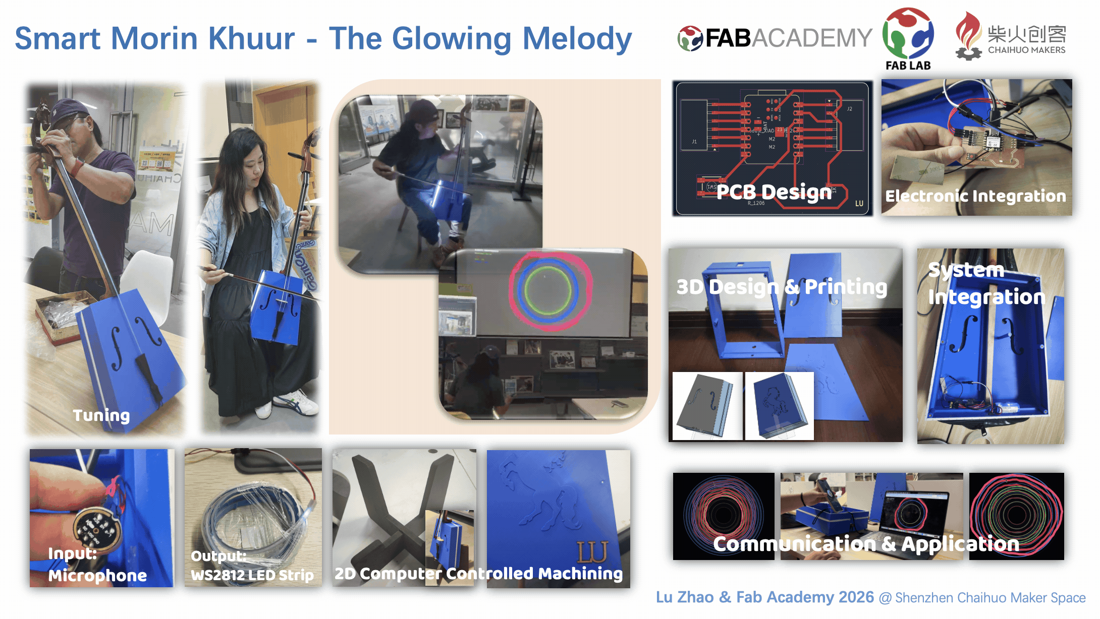
Final Project: Smart Morin Khuur - The Glowing Melodies
Presentation Slide & Video:
1. Project Concept & Motivation
The idea for my final project comes from my two passions: music and making. I’m currently a drummer in our company band at Seeed Studio, and recently, I’ve started learning a beautiful traditional Mongolian instrument—the Morin Khuur (Horsehead Fiddle).
While the Morin Khuur has a deep, soul-stirring sound, I feel it could have a more modern "stage presence." I want to design an interactive 3D-printed enclosure that fits onto the instrument. The goal is to have the fiddle "react" to the music I'm playing. I think it would be amazing to see the instrument glow and change colors in sync with the rhythm during a performance, bringing a traditional piece of art into the modern "Maker" world.
2. Original Idea Sketch & Design
I’ve put together a conceptual sketch to visualize how this would look.
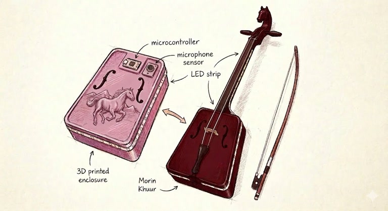
(The sketch of idea is generated by Google Gemini)
Key features of my design:
-
Artistic Enclosure: I’m planning to 3D print a pink-purple shell that goes over the soundbox. It will have a galloping horse relief to match the "Horsehead" theme.
-
Respecting the Instrument: I’ll make sure the shell has the same "F-holes" as the original fiddle so the sound isn't muffled.
-
Lighting: I want to place LED strips along the neck and the edges of the new shell to create a cool atmosphere.
3. How I imagine it working
I want the system to be quite simple but effective. It’s basically a "Hear and React" system:
-
Picking up the sound: I'll add a small microphone sensor to the enclosure. This will be the "ear" of the project, listening to the volume and the beat of my playing.
-
The "Brain": Inside the shell, there will be a microcontroller. I don't need anything too complex; it just needs to take the signal from the microphone and tell the lights what to do.
-
The Visuals: Based on how loud or fast I play, the LED strips will change. For a slow, sad song, maybe they'll breathe slowly in blue; for a fast, upbeat song, they could flash more energetically.
Since I'm still quite new to the technical side of things, my main focus for Fab Academy will be figuring out how to make this shell fit perfectly and getting the lights to sync up nicely with the music.
Acoustic Engineering & DfAM Considerations for the Morin Khuur
Designing a 3D-printed acoustic instrument requires striking a delicate balance between traditional lutherie principles and the unique constraints of Additive Manufacturing (DfAM). Below is a summary of the acoustic and structural strategies implemented in this digital Morin Khuur project.
Material Selection & Resonance (Stiffness-to-Weight Ratio)
The acoustic performance of a soundbox heavily relies on its material's stiffness-to-weight ratio.
-
The FDM Choice (PETG/PLA+): While standard 3D printing resins (SLA/DLP) are too dense and acoustically "dead" (dampening vibrations), FDM materials like PLA+ and PETG offer a much better acoustic profile. They provide adequate stiffness to produce clear, bright overtones.
-
Wall Thickness Optimization: To ensure the soundboard resonates freely without collapsing under string tension, the shell thickness was strictly set to 3.0mm. Thicker walls would absorb high frequencies, while thinner walls would risk structural warping.
Internal Acoustic Architecture
Instead of mimicking traditional wooden instrument construction, the internal acoustic components were re-engineered specifically for 3D printing:
-
Integrated Bass Bar (DfAM): In traditional string instruments, the bass bar distributes low-frequency vibrations and prevents the soundboard from collapsing. Instead of gluing a separate piece, I parametrically modeled the bass bar as a continuous structural rib directly into the inner soundboard. It spans 240mm (roughly 80% of the board's length) and utilizes a 5-degree draft angle, creating a trapezoidal cross-section that maximizes compressive strength while minimizing excess mass that could dampen the sound.
-
Friction-Fit Sound Post: The sound post acts as the acoustic "soul," transmitting high-frequency vibrations from the soundboard to the backboard. To function correctly, it cannot be glued; it must wedge tightly through friction. Using Onshape's
Up to faceparametric extrusion, the software calculated the exact collision distance between the front and back panels, generating an independent 8mm cylindrical post that fits flawlessly. -
Custom F-Holes Placement: The custom spline-based sound holes were deliberately offset from the center to leave a wide, uninterrupted "central highway" for the bass bar and sound post to effectively transmit vibrations.
Acoustic Sealing and Anti-Buzz Assembly
When combining 3D-printed plastic parts under high tension, microscopic gaps can cause severe acoustic issues, including low-frequency air leaks and harsh plastic-on-plastic buzzing.
-
The Gasket Solution: Instead of using irreversible epoxy resin (which would prevent future acoustic tuning), I incorporated a 1mm single-sided EVA foam gasket between the soundboards and the middle frame.
-
Acoustic Airtightness: Secured by the mechanical tension of the M3 heat-set inserts and screws, the 1mm foam compresses almost entirely. This creates a perfect airtight acoustic cavity—essential for a deep, resonant bass response—while completely eliminating any parasitic buzzing caused by resonant friction.
-
Load Distribution (Tailgut Saddle): At the base of the soundbox where the tailgut anchors the strings, the concentrated inward tension is immense. I designed a thickened Trapezoidal Saddle at the edge to safely distribute this mechanical load, ensuring the 3mm plastic soundboard does not deform or crack over time.
Conceptual Visualization & Systems Integration
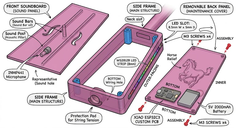
Before diving into the parametric CAD modeling, I developed a detailed conceptual visualization (see image below) to map out the internal layout of the Morin Khuur. My primary engineering goal was the seamless integration of traditional acoustic mechanics with digital interactivity within a unified 3D-printed enclosure.
-
Embedded Reactive Components: I planned dedicated structural slots and routing paths directly within the main frame to house the WS2812 LED strip and the INMP441 Microphone. This ensures the electronics are securely mounted without rattling or disrupting the internal acoustic cavity.
-
Modular Maintenance Back Panel: To prioritize ease of assembly and future debugging, the core processing unit (XIAO ESP32C3 with custom PCB) and the 5V 2000mAh Battery are designed to be mounted onto the removable back panel. This creates an accessible "electronics bay" separated from the main acoustic chamber.
-
Re-imagined Acoustic Architecture: The visualization clearly maps out the placement of the integrated Sound Bars and the friction-fit Sound Post, ensuring they align perfectly with the bridge to maximize high-frequency transmission.
-
Mechanical Tension Reinforcement: I specifically highlighted the bottom anchor area to include a thickened Protection Pad (Tailpiece Saddle). This is a critical structural reinforcement designed to safely distribute the extreme downward mechanical tension exerted by the instrument's strings, preventing the plastic from cracking over time.
(The sketch of more detailed original design is generated by Google Gemini)
3D Structure Design & 3D Printing
This project aims to seamlessly merge a traditional Mongolian Morin Khuur with modern digital fabrication and interactive LED hardware. Rather than building from scratch, this is a complex semi-reverse engineering task, designed to preserve the original wooden neck and endpin while completely reconstructing the acoustic resonance chamber using 3D printing.
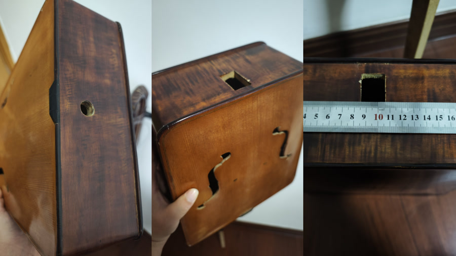
To better manage the dimension of the structure and and the acoustic effect, I disassembled the original Morin Khuur and detailedly measured the dimension, and also did some study on the sound-producing principle of this musical instrument.
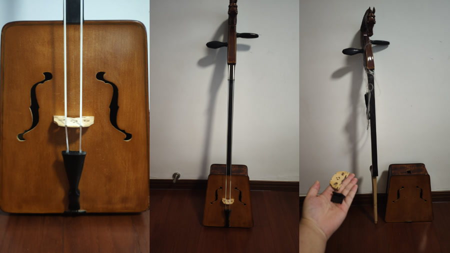
A critical challenge was ensuring precision tolerances and fit. The new 3D-printed body must withstand immense string tension and mate perfectly with the original wooden parts.
Middle frame
I designed middle frame first since it's the key structure which has the responsibility to connect to the neck, I then designed front panel and backplate as second & third step. The middle frame is the structural backbone of the instrument. Modeling this part in Onshape required navigating several geometric limits and digital fabrication constraints.
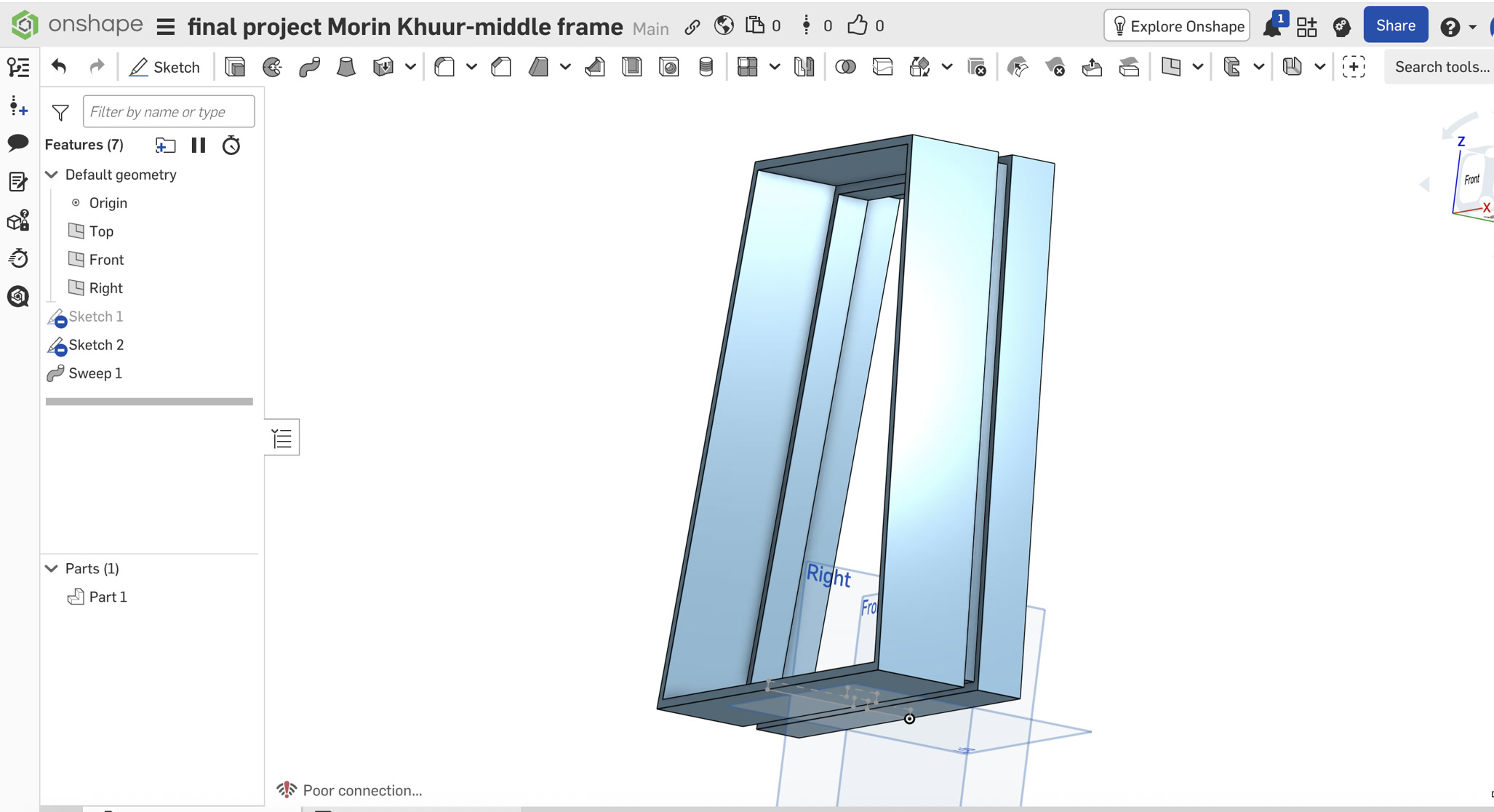
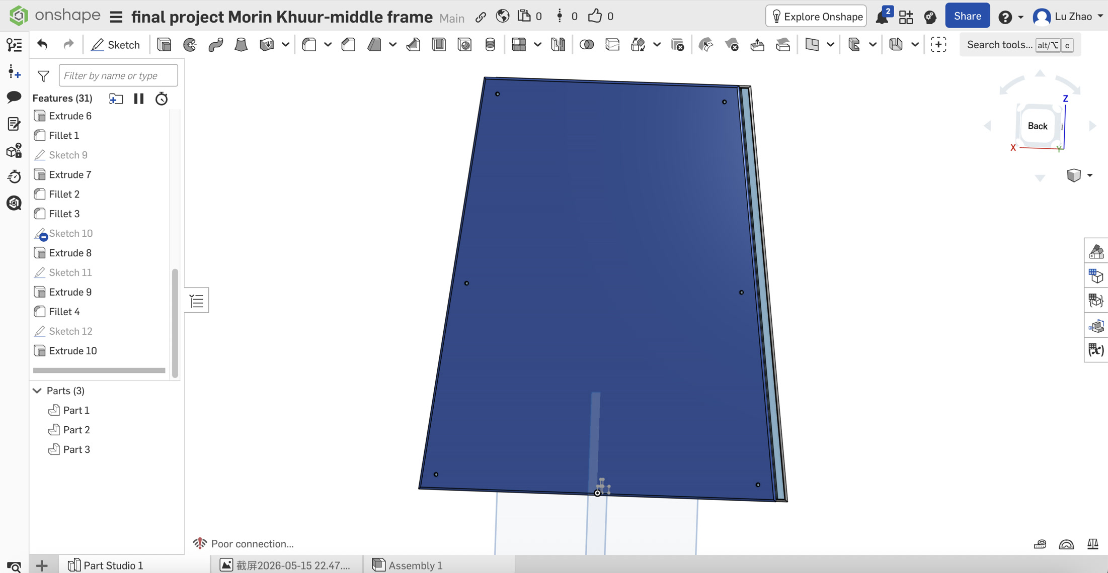
I began by sketching the classic trapezoid profile (top 190mm, bottom 267mm, height 310mm) and a cross-section profile featuring a 5mm wall thickness and the external LED groove.
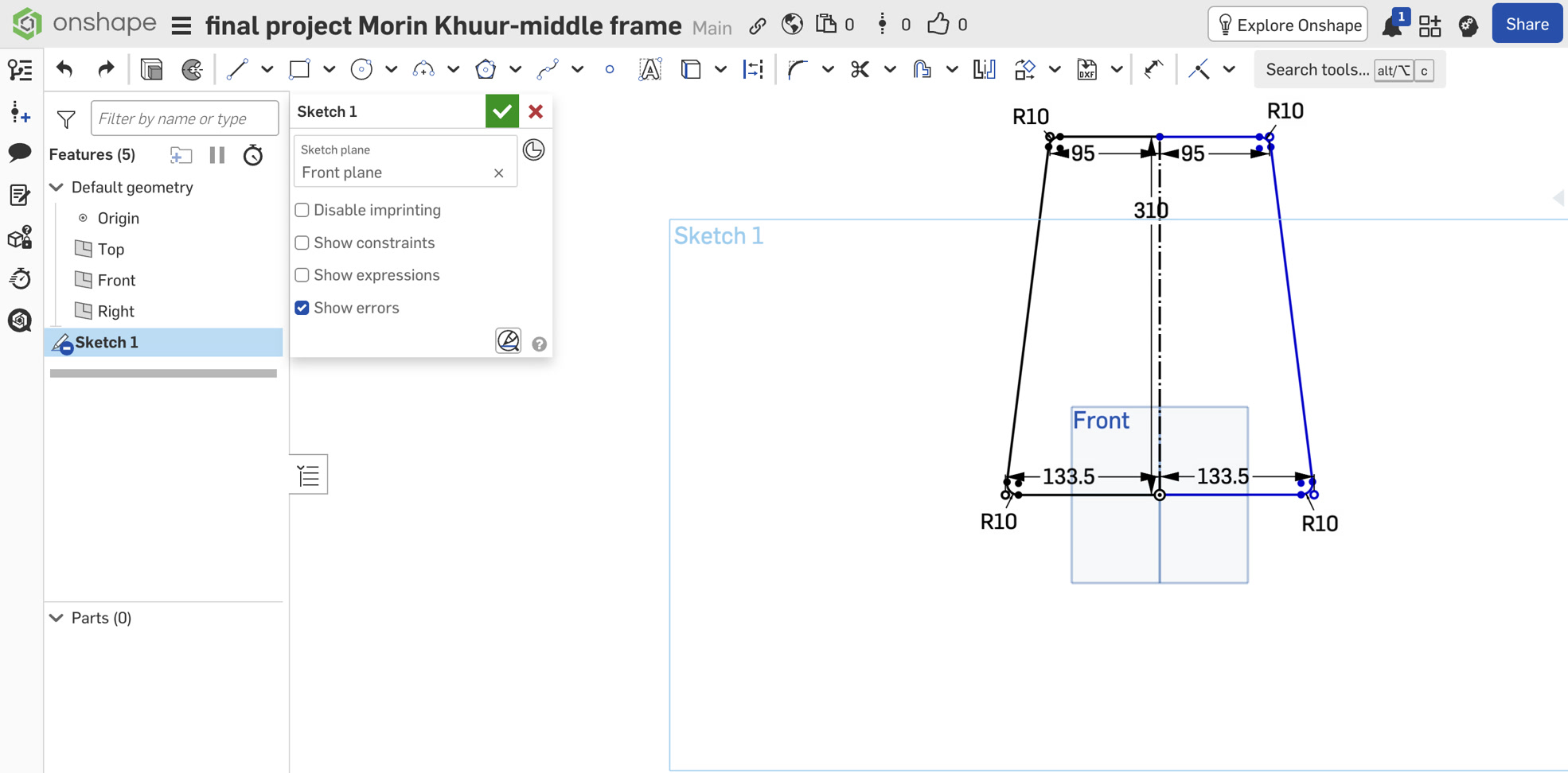
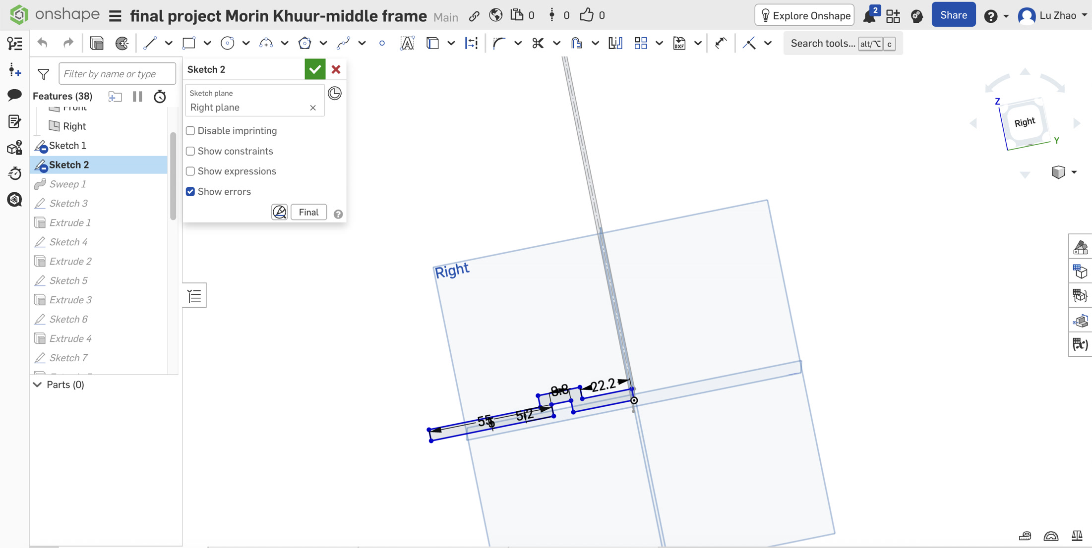
For the embedded electronics, aesthetics were just as important as function. Instead of simply sticking LED strips to the exterior, I designed an integrated 8.8mm wide LED light channel along the rear outer edge, allowing the lights to sit flush with the surface. To maintain a clean industrial look, a 10mm hidden wire slot was routed from the bottom of this groove directly into the acoustic chamber, completely concealing the power cables.
My initial approach was to sweep this profile along a path with 10mm corner fillets to generate the 91mm thick body. However, the extreme thickness caused the inner geometry to overlap at the tight corners, triggering a fatal Self-Intersection error.
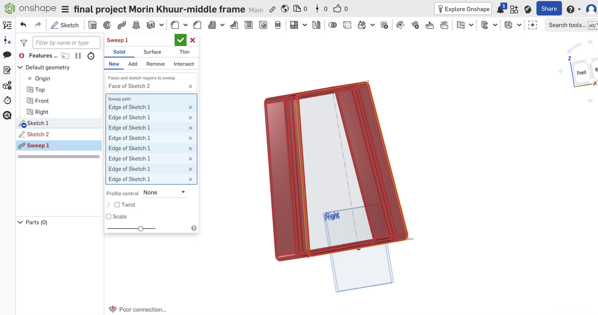
To bypass this geometric limitation, I adopted a "block out first, detail later" approach. I removed the fillets from the sketch, generated the main body using sharp Miter corners during the Sweep.
Based on precise caliper measurements, I designed the top neck slot at 36 x 21.5mm.
For the bottom endpin (measured at 17mm), I deliberately enlarged the CAD hole to 17.5mm to account for the thermal shrinkage of PLA/Resin materials. This 0.5mm tolerance ensures a snug, structural press-fit without the risk of splitting the 3D-printed layers.
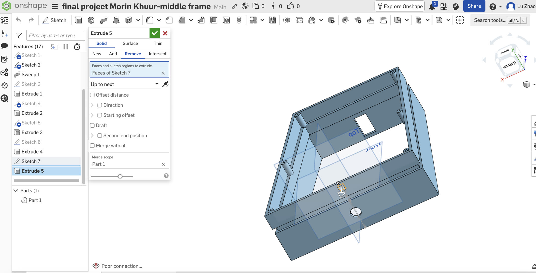
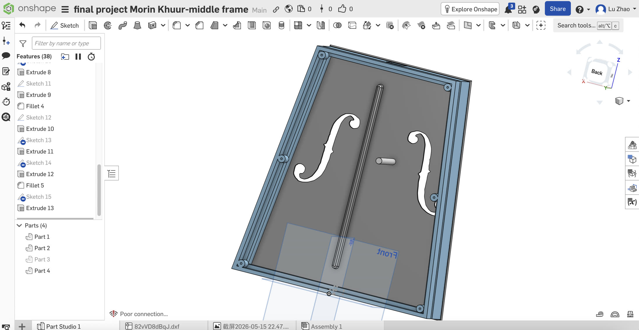
A critical design decision was how to securely attach the 3mm soundboard and backboard. Since 3D-printed plastics (PETG/PLA+) are prone to stripping if tapped directly, I engineered a mechanical fastening system utilizing M3 Brass Heat-Set Threaded Inserts and M3 Hex Socket Head Cap Screws. This allows for repeated disassembly for future acoustic tuning without degrading the threads.
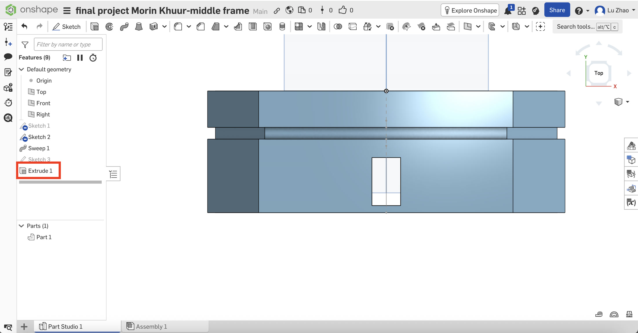
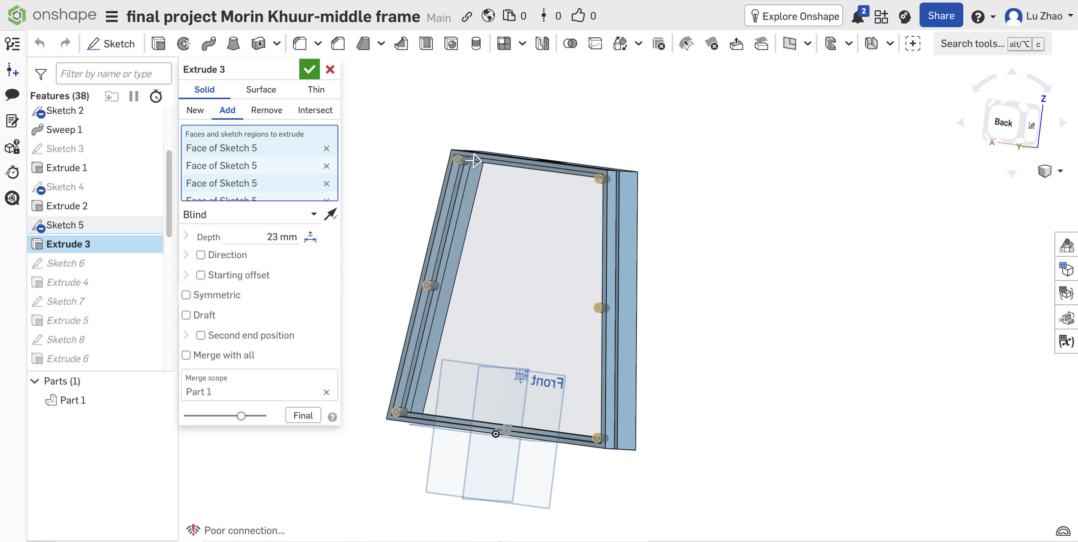
I sketched six 10mm circles on the rear face and needed to extrude them into the hollow chamber. The actual measured distance to the inner wall of the LED groove was 22.2mm. If I extruded exactly 22.2mm, it would create a zero-thickness condition, often leading to non-manifold geometry errors. To solve this, I intentionally set the extrusion depth to 23mm using the Boolean Add operation. This forced the posts to intersect the inner wall by 0.8mm. The software flawlessly melted this overlap together, creating ultra-strong, stepped reinforcement ribs without any errors. Finally, I cut 20mm deep blind holes (2.5mm diameter) into these posts for the screws, purposefully leaving a solid 3mm base to guarantee zero light leakage and absolute acoustic airtightness.
Parametric Tolerance Adjustment: I sourced M3 inserts with a 5mm outer diameter (D5). In Onshape, I parametrically updated my pre-modeled blind screw holes from exactly 3.0mm to 4.7mm. This specific 0.3mm interference fit ensures that when the insert is pressed in with a soldering iron, the melted plastic flows perfectly into the knurling, creating a permanent, industrial-grade bond.
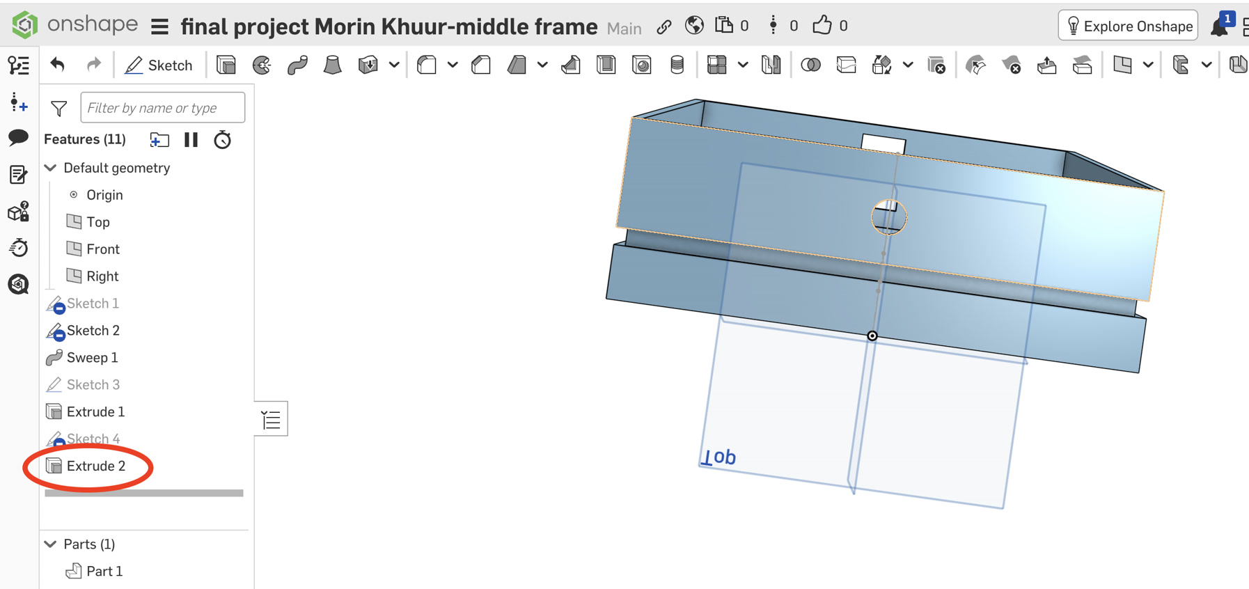
Since most electronic components will be hidden inside the case and the LED strip shall go out, I opened a 10mm * 10mm slot for the LED cable.
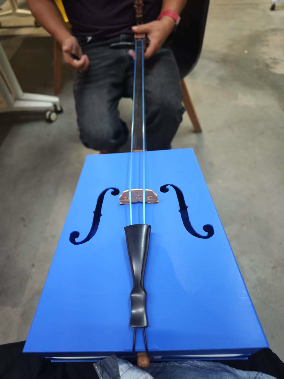
The Soundboard (Front Panel): Acoustics & Load Distribution
The soundboard was extruded to 3mm thick to balance resonance and structural integrity. It features classic F-holes and a reinforced lower bout to handle the extreme string tension.
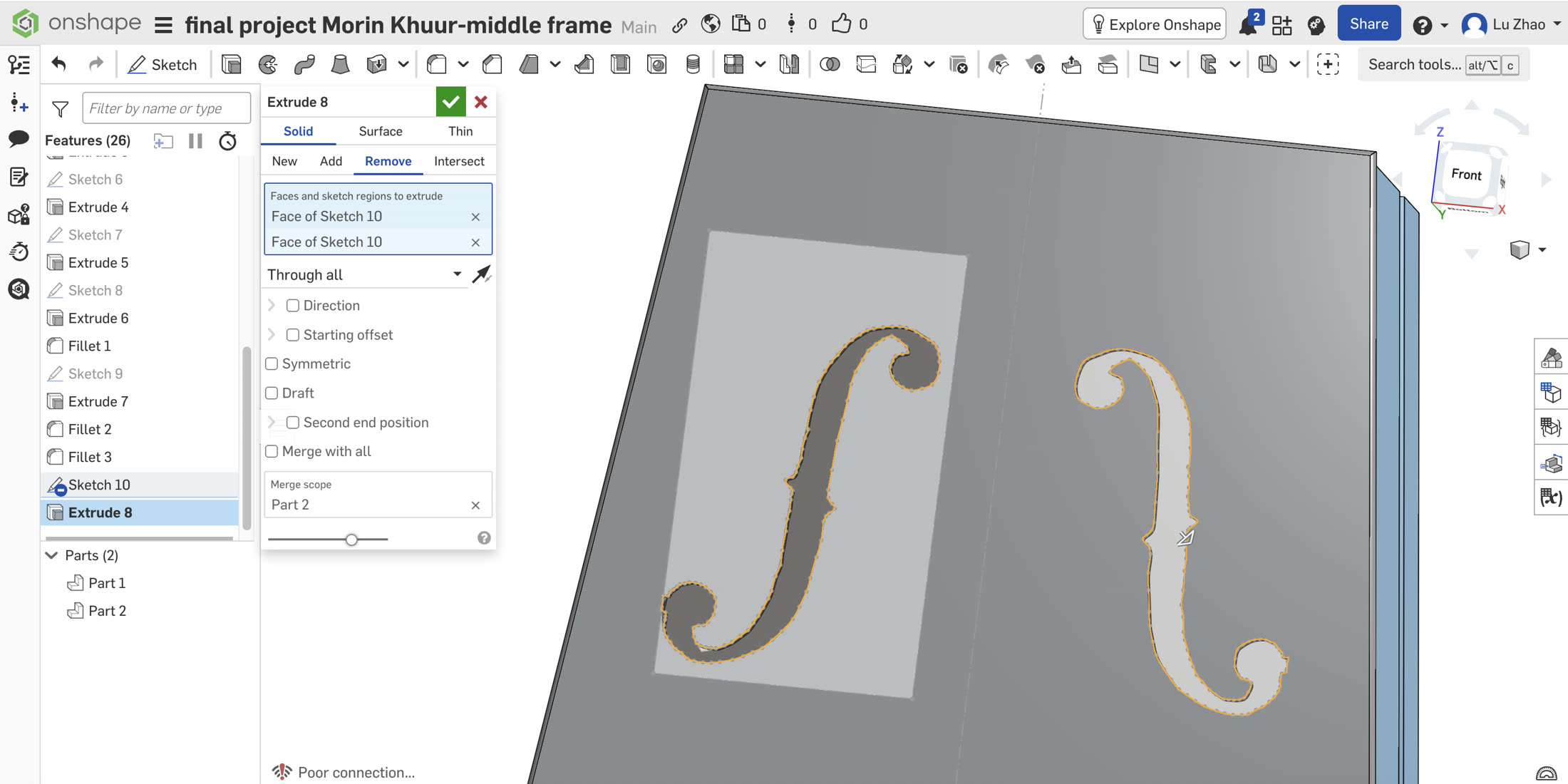
- Classic F-Holes: I imported a reference image of violin "F-holes" into the sketch. I used the
Splinetool to trace the complex curves. A key lesson learned was managing "Unwanted Snapping"—the splines kept snapping to the image's bounding box. I resolved this by completely deleting the reference image after tracing, breaking the coincident constraints. I then used theMirrortool for acoustic symmetry and cut the holes usingExtrude (Remove).
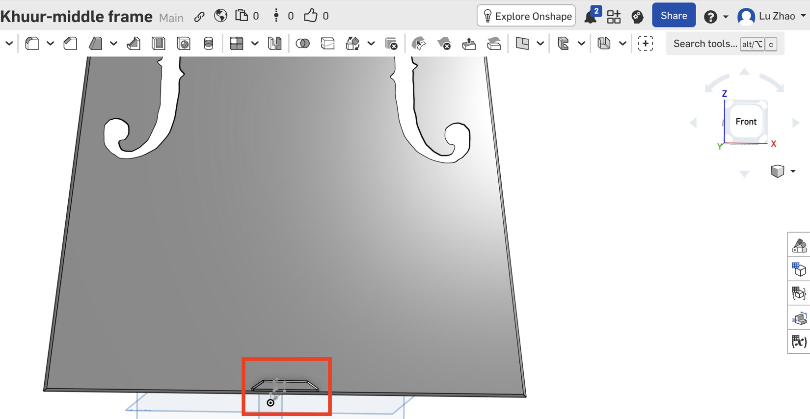
- The Tailgut Saddle (Lower Trapezoid Reinforcement): At the bottom edge of the panel, the tailgut (which anchors the tailpiece) exerts massive concentrated inward pressure. To prevent the wire from biting into and crushing the 3mm plastic edge, I sketched a custom Trapezoidal Saddle. I extruded this shape to create a thicker, reinforced contact point that safely distributes the mechanical load across the lower bout.
- The Bass Bar (Structural Integration): Instead of gluing a separate wooden strip like traditional lutherie, I designed the bass bar as an integrated structural rib. On the inner soundboard, I used the
Slottool to create a 240mm long capsule profile under the bass string position. Crucially, when extruding it to 10mm height, I applied a5-degree Draftangle. This created a trapezoidal "bridge pier" cross-section, exponentially increasing its compressive strength against the downward string tension.
- The Sound Post (Parametric Fit): The sound post transmits high-frequency vibrations to the backboard. It must be an independent physical piece held purely by friction. I sketched an 8mm circle on the inner soundboard and used
Extrude (New)to create a separate part (Part 4). By changing the end condition toUp to faceand selecting the backboard's inner surface, the software automatically calculated the exact collision distance, ensuring a perfect physical wedge fit without measuring.
The Backboard
- Parametric Assembly (Clearance Holes): To ensure the backboard perfectly aligned with the middle frame's heat-set inserts during physical assembly, I utilized Onshape's relational design features. In the backboard sketch, I used the
Use (Project / Convert)tool to extract the exact center points of the screw holes directly from the Middle Frame (Part 1). I then usedExtrude (Remove)to punch precise M3 clearance holes through the backboard, guaranteeing zero misalignment.
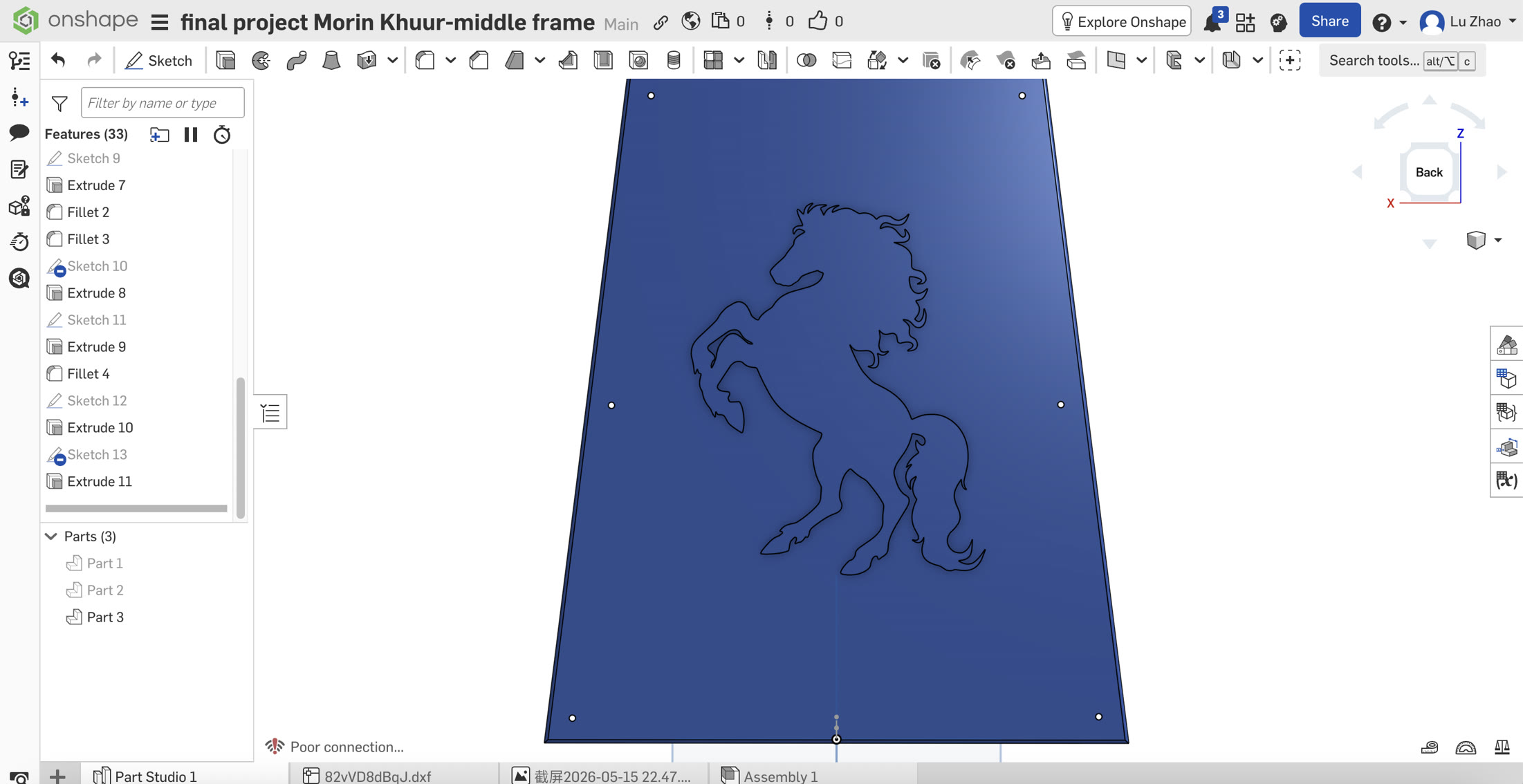
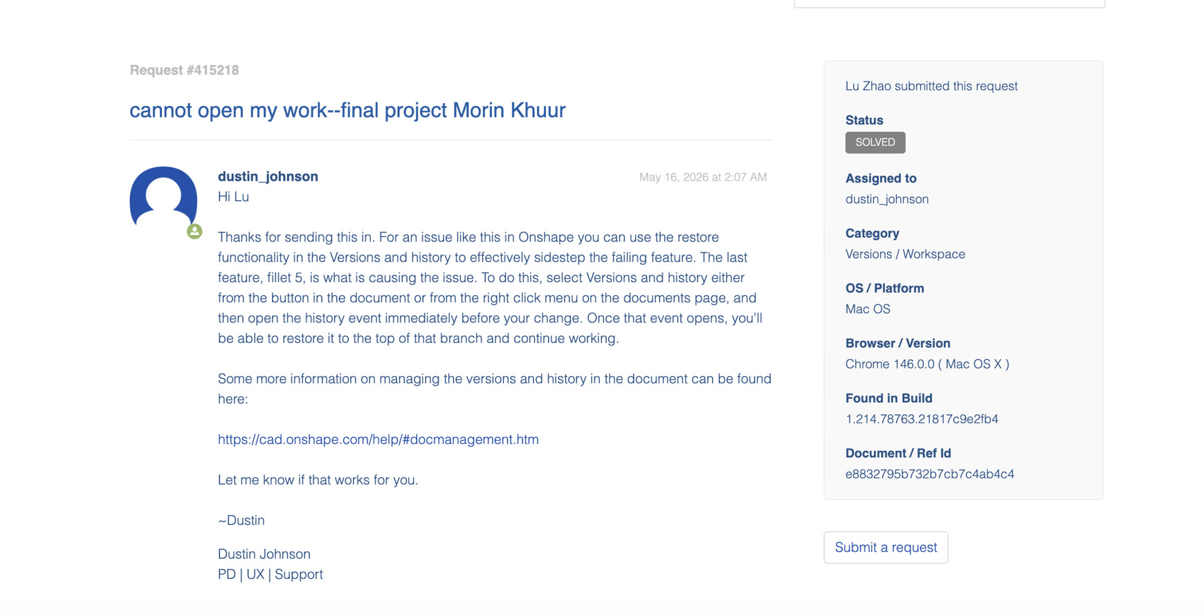
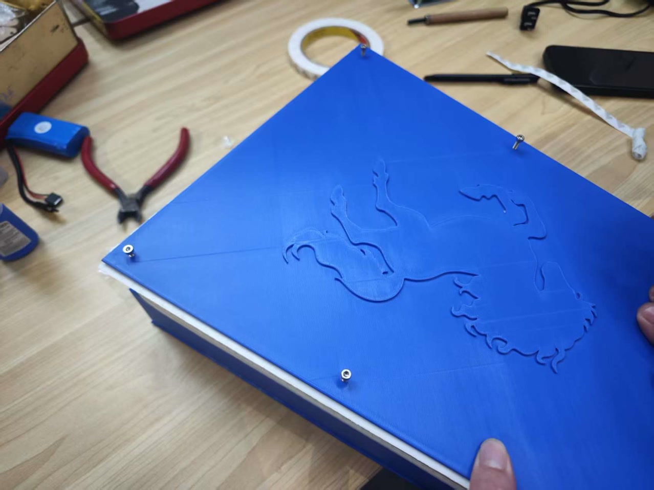
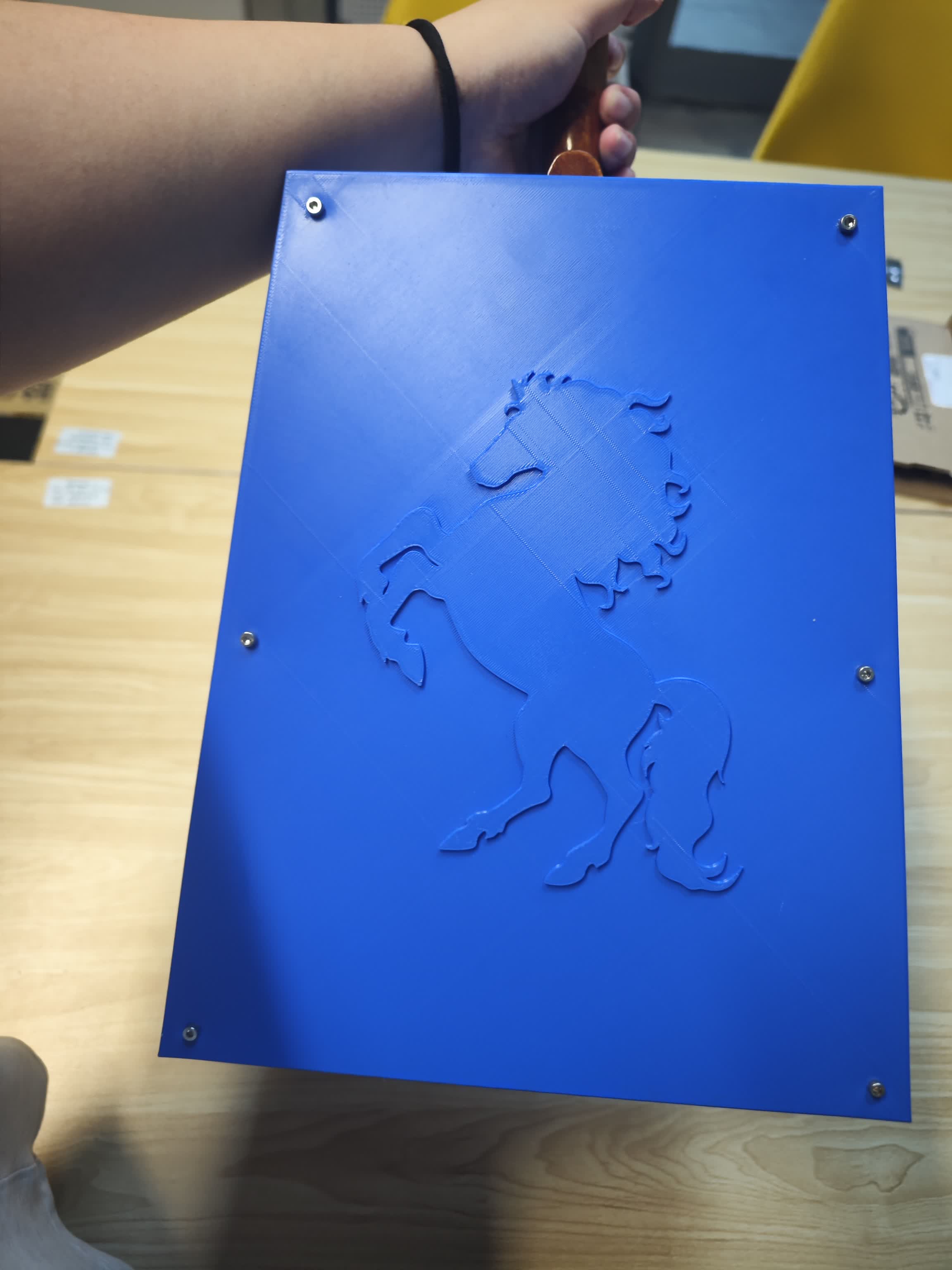
- Cultural Relief & Troubleshooting a Critical CAD Crash: To add a cultural touch, I imported a 2D DXF vector graphic of a galloping horse and extruded it (1.5mm) to create a 3D relief on the backboard. However, this process led to a severe workflow failure. After generating the horse relief, I attempted to apply a
Filletto the generated edges. This created a topological nightmare: the microscopic sharp corners in the imported DXF splines caused the fillet algorithm to infinitely loop, crashing the Onshape cloud engine and completely locking my document. I contacted Onshape Tech Support, who helped identify the root cause. To rescue the project, I utilized Onshape'sVersion Historyfeature to roll back the entire workspace to a stable state just before the catastrophic fillet operation, successfully saving my prior work without starting over.
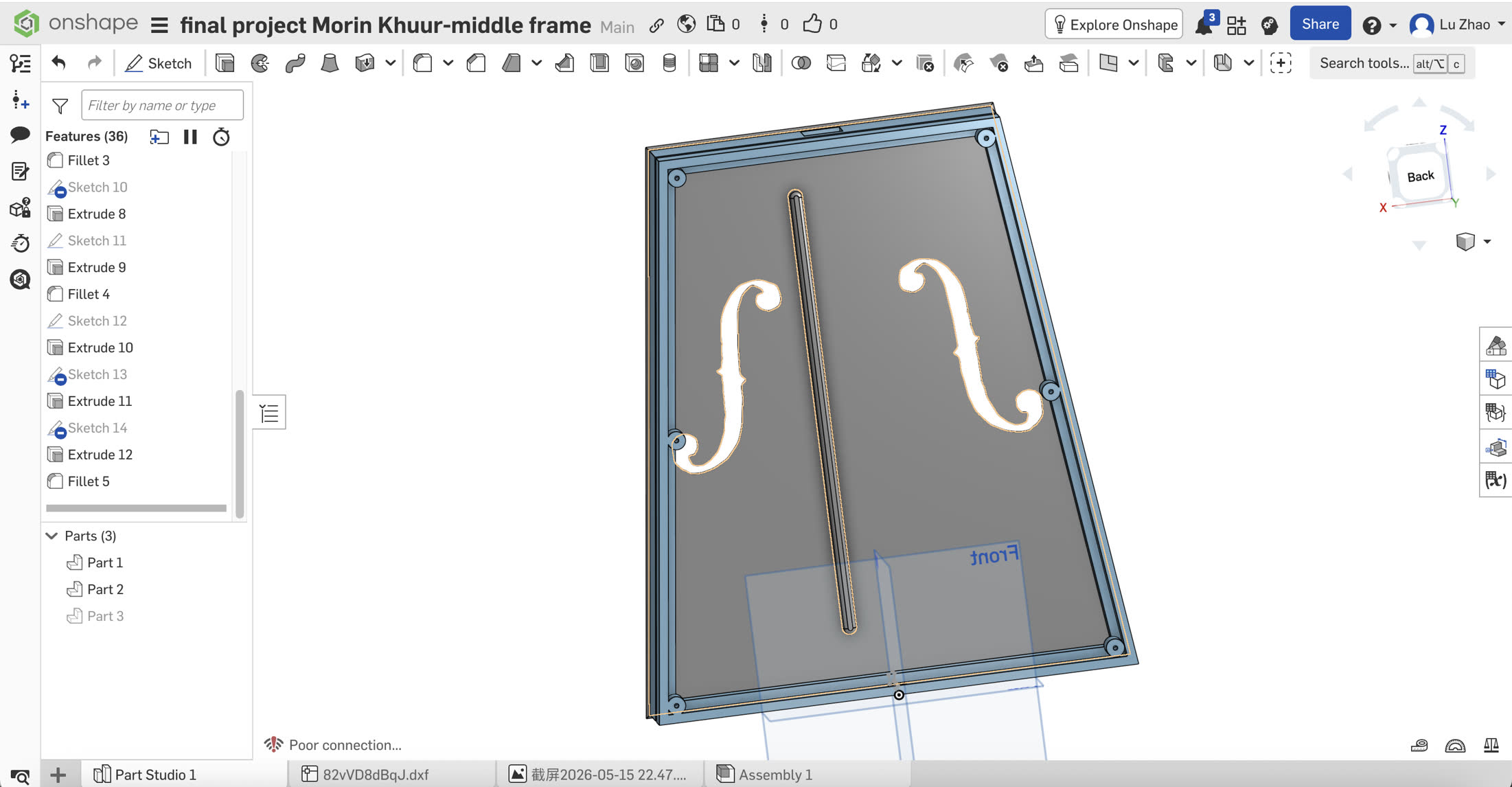
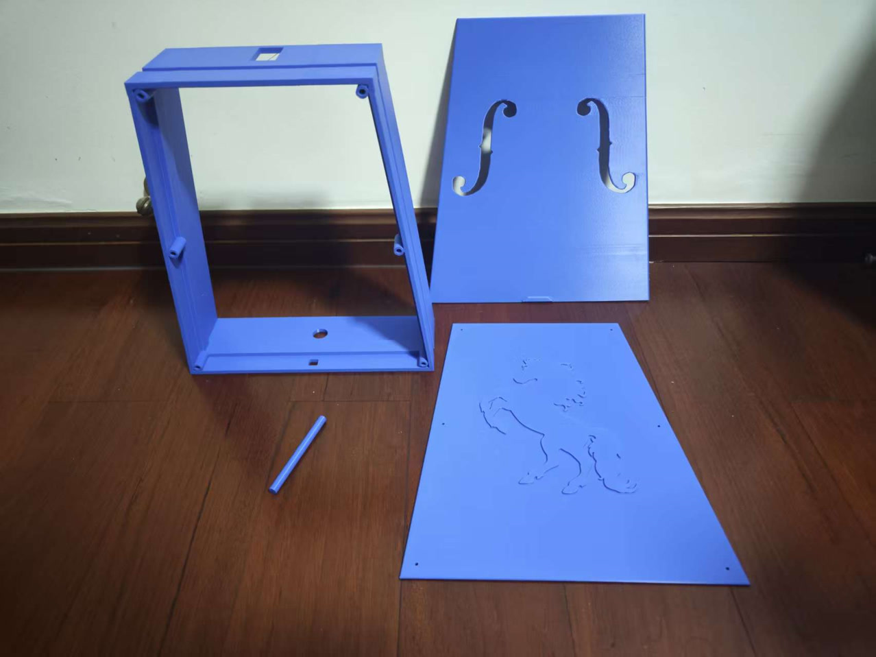
Structure Summary
I got my final structure design work as below:
3D Printing
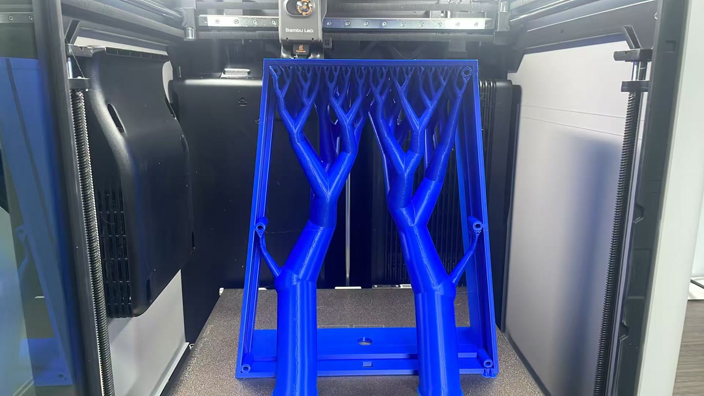
Machine Constraints & Outsourcing Rationale: Our makerspace is equipped with a Bambu Lab A1 3D printer, which has a limited build volume. Because the structural dimensions of my Morin Khuur soundbox exceeded this printable area, I could not fabricate it locally. To overcome this hardware limitation without splitting the model (which would severely compromise structural strength and acoustic airtightness), I outsourced the fabrication to a professional industrial 3D printing bureau - Dongguan Keheng, amoung almost 10 printing bureaus which I consulted, because their material and printing technique/equipement can meet my printing specification requirements, I contacted their sales representative and went to their studio to print it myself.
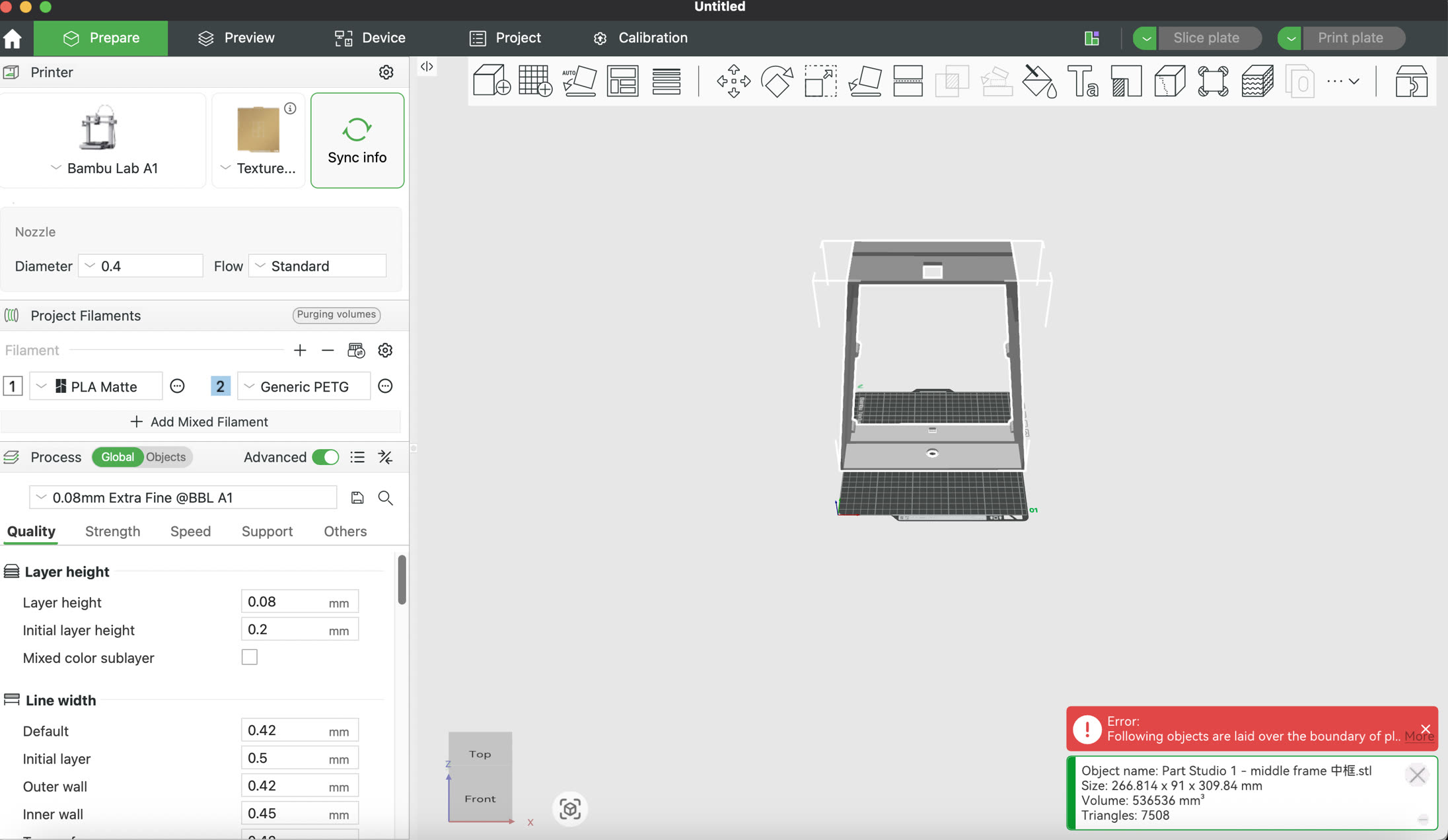
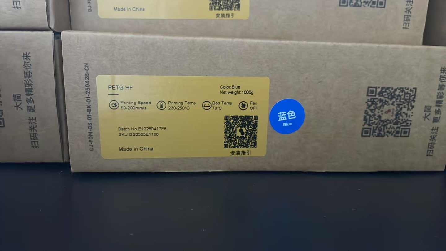
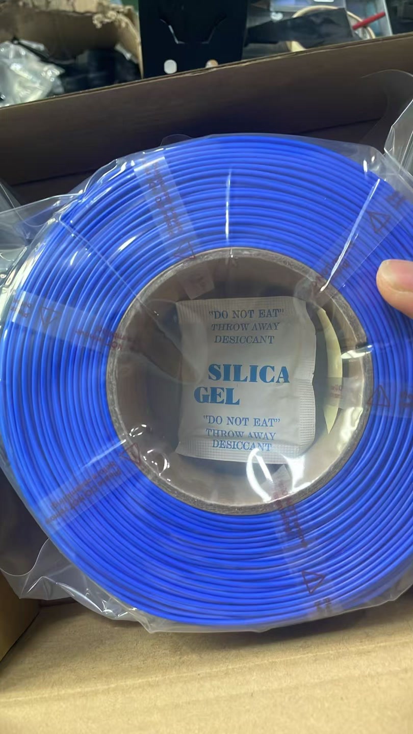
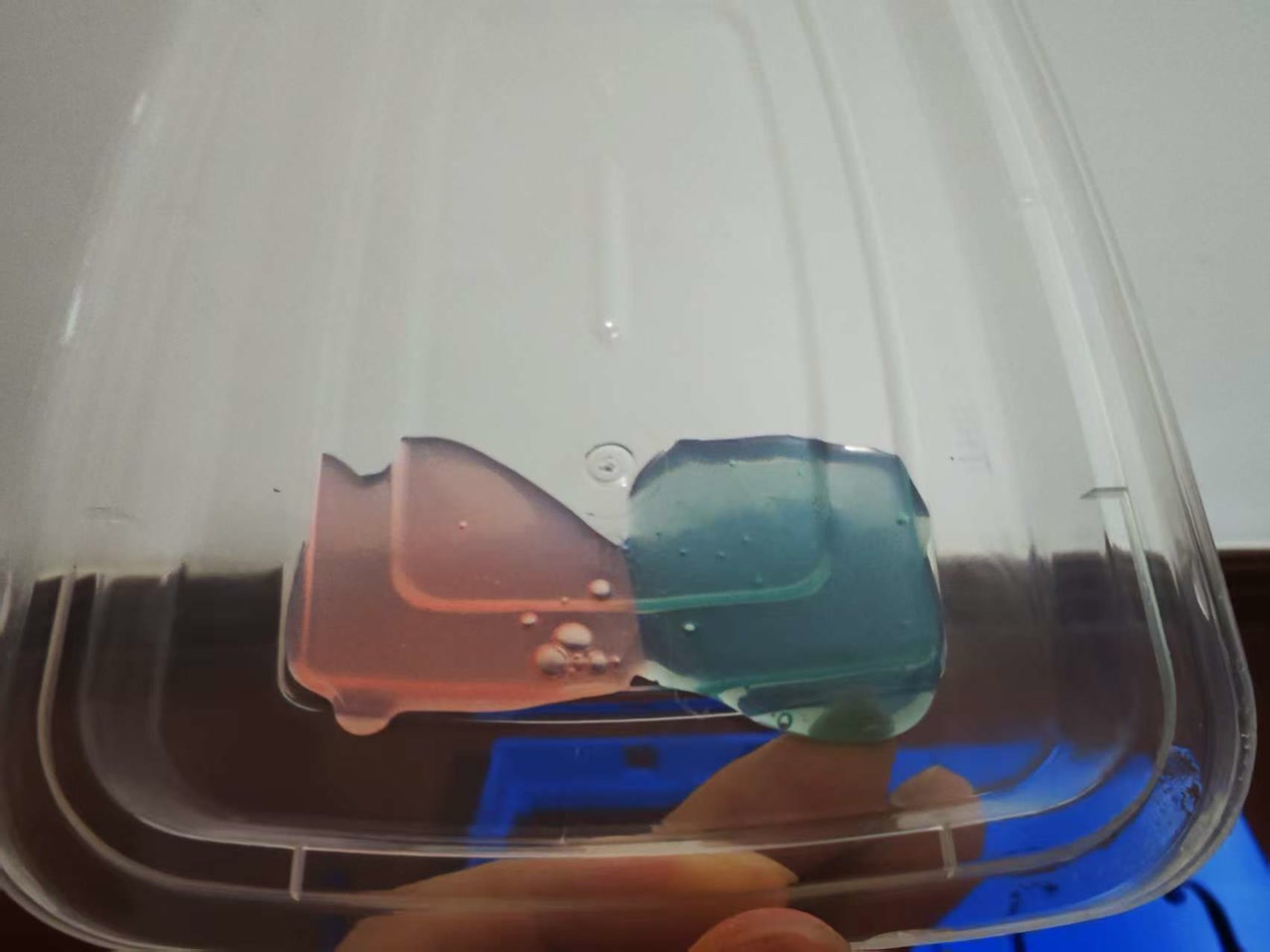
Material Selection & General Parameters: I selected PETG as the primary manufacturing material. Compared to standard PLA, PETG offers superior tensile strength, impact resistance, and weather durability, which are critical for an instrument under constant string tension. A layer height of 0.2mm was applied across all parts to achieve an optimal balance between strong interlayer adhesion and a smooth surface finish.
Slicing Strategy & Structural Rationale: Different slicing parameters were strategically assigned to individual components based on their mechanical and acoustic roles:
- Middle Frame (The Structural Core): I configured this part with 35% - 40% Infill Density and 4 Wall Lines (Perimeters). The middle frame acts as the primary load-bearing skeleton connecting the neck and resisting string tension. Maximizing the wall count and maintaining a high infill density provides the necessary rigidity to prevent any mechanical twisting or deformation over time.
-
Soundboard & Backboard (Acoustic Panels): For these panels, I used 20% - 25% Infill Density with Gyroid or Honeycomb infill patterns. The front and back panels need to balance structural flatness with acoustic flexibility. The three-dimensional, isotropic nature of the Gyroid pattern provides uniform structural support while creating internal resonant pathways that enhance acoustic projection rather than dampening the sound waves.
-
Sound Post (Acoustic Pillar): This component was printed with 100% Solid Infill. The sound post serves as the critical energy conduit transmitting high-frequency vibrations from the front panel to the back panel. Printing it completely solid ensures maximum material density, eliminating any internal air gaps that could scatter sound waves, which guarantees optimal acoustic conductivity and compression resistance.

2D Logo Design & Laser Cutting
Design Rationale & Aesthetics
To fulfill the 2D subtractive manufacturing requirement for the final project, I designed a custom wooden monogram featuring my initials, "LU". The conceptual goal was to introduce a touch of traditional, organic craftsmanship (wood) to an otherwise highly digital, 3D-printed electronic instrument. I specifically selected the Roboto Slab font. Its thick, geometric serifs provide a robust structural foundation for laser cutting, while its mechanical yet classic appearance perfectly bridges the gap between digital engineering and traditional lutherie.
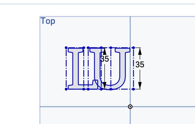
- I initiated a new sketch on the Top plane and utilized the Text tool to create the letters "L" and "U" as two completely separate text entities. I assigned both letters the Roboto Slab font to ensure they shared the same serif thickness and geometric style. The height is 35mm.
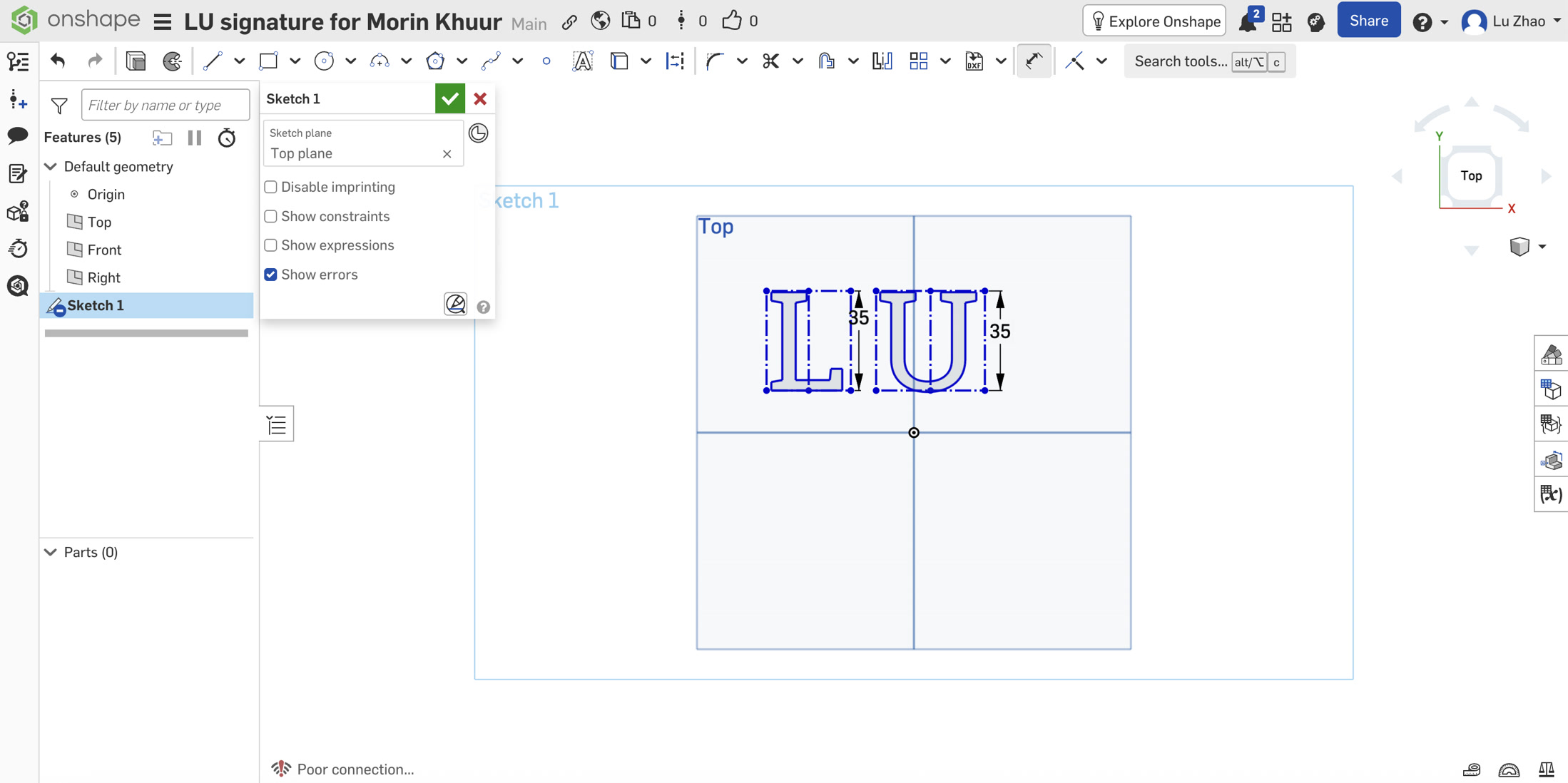
- To create a unified logo, I manually dragged the individual text boundaries toward each other. I carefully aligned them so that the heavy bottom horizontal stroke of the "L" structurally intersected with the bottom left corner of the "U", creating a visually balanced overlap.
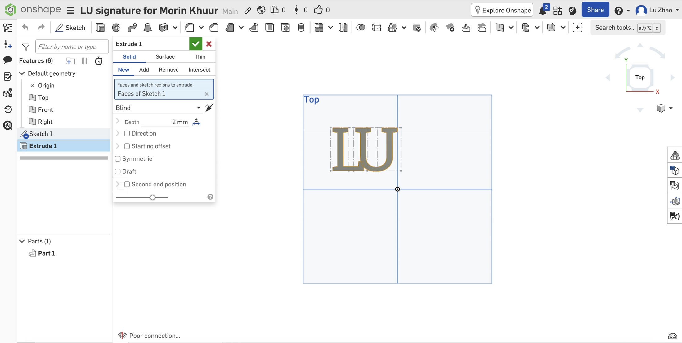
- Instead of struggling to manually trim the complex, overlapping 2D splines (which often causes constraint errors), I applied a 3D operation to solve a 2D problem. I used the Extrude tool set to Solid with a random depth (e.g., 2mm). Onshape automatically executed a Boolean union, melting the two overlapping letters into a single, seamless 3D part and eliminating all internal crossing lines.
Laser Cutting & Assembly
For the physical logo, I chose 3mm Basswood Plywood.
In the RDWorks software, I set the speed to 30mm/s, MinPower 75%, MaxPower 90% to make sure it can cut through.
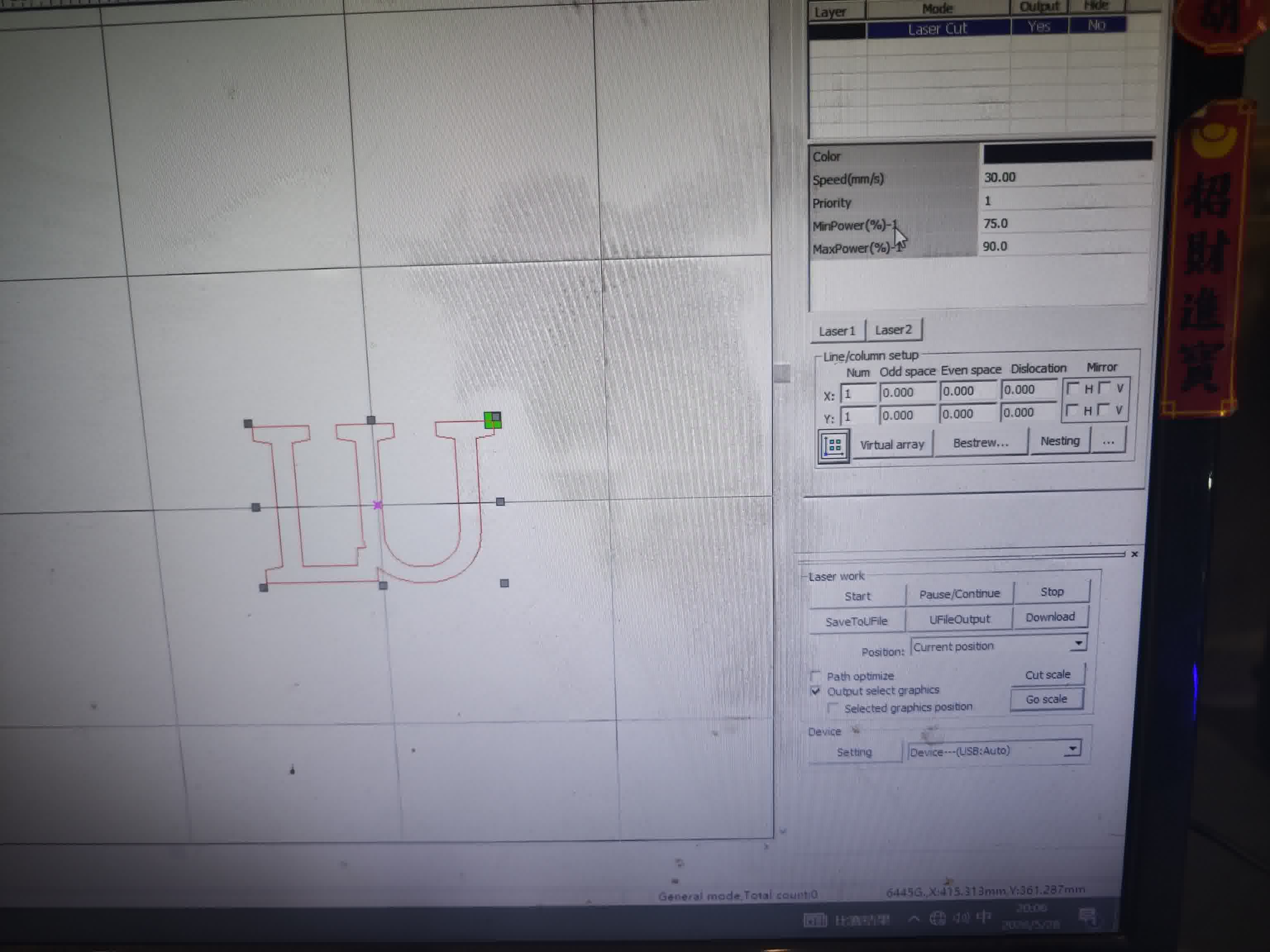
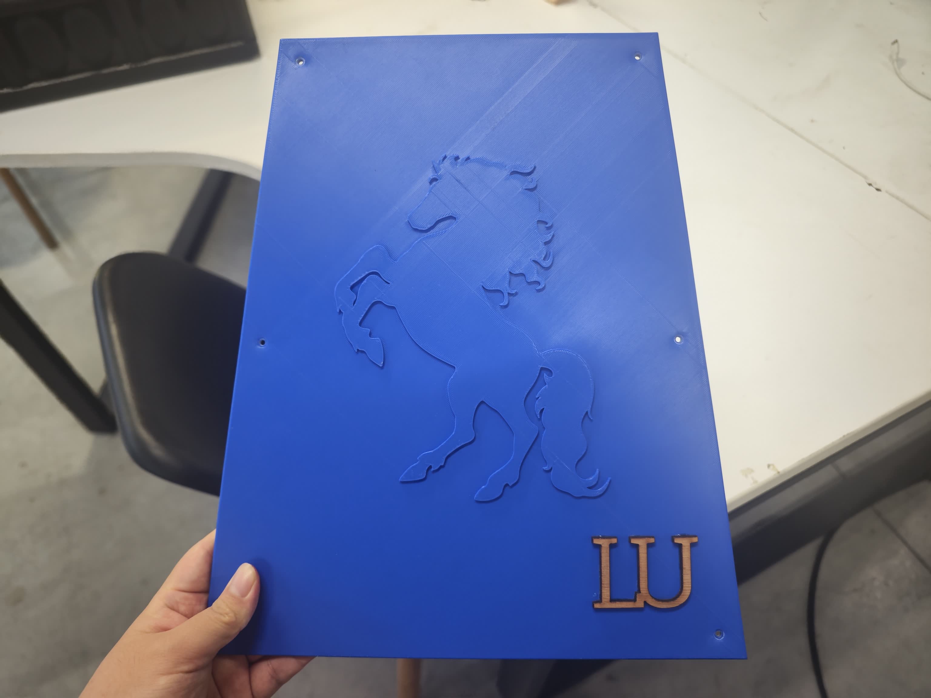
The main consideration here was aesthetics: the laser cutter naturally burns the wood during the process, leaving a dark, carbonized edge. I really like this effect because it makes the letters pop out against both the pale wood grain and the translucent 3D-printed PETG backboard.
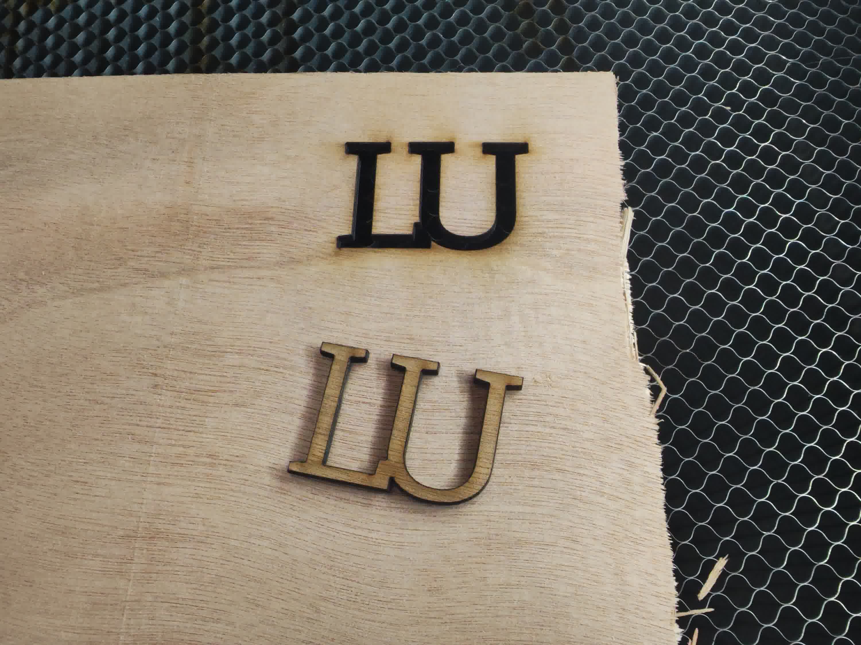
After taking the piece out of the laser bed, to mount it, I simply used a few drops of glue to attach the wooden monogram directly to the rear maintenance panel. It’s a relatively small detail, but it gives the instrument a great personal touch.
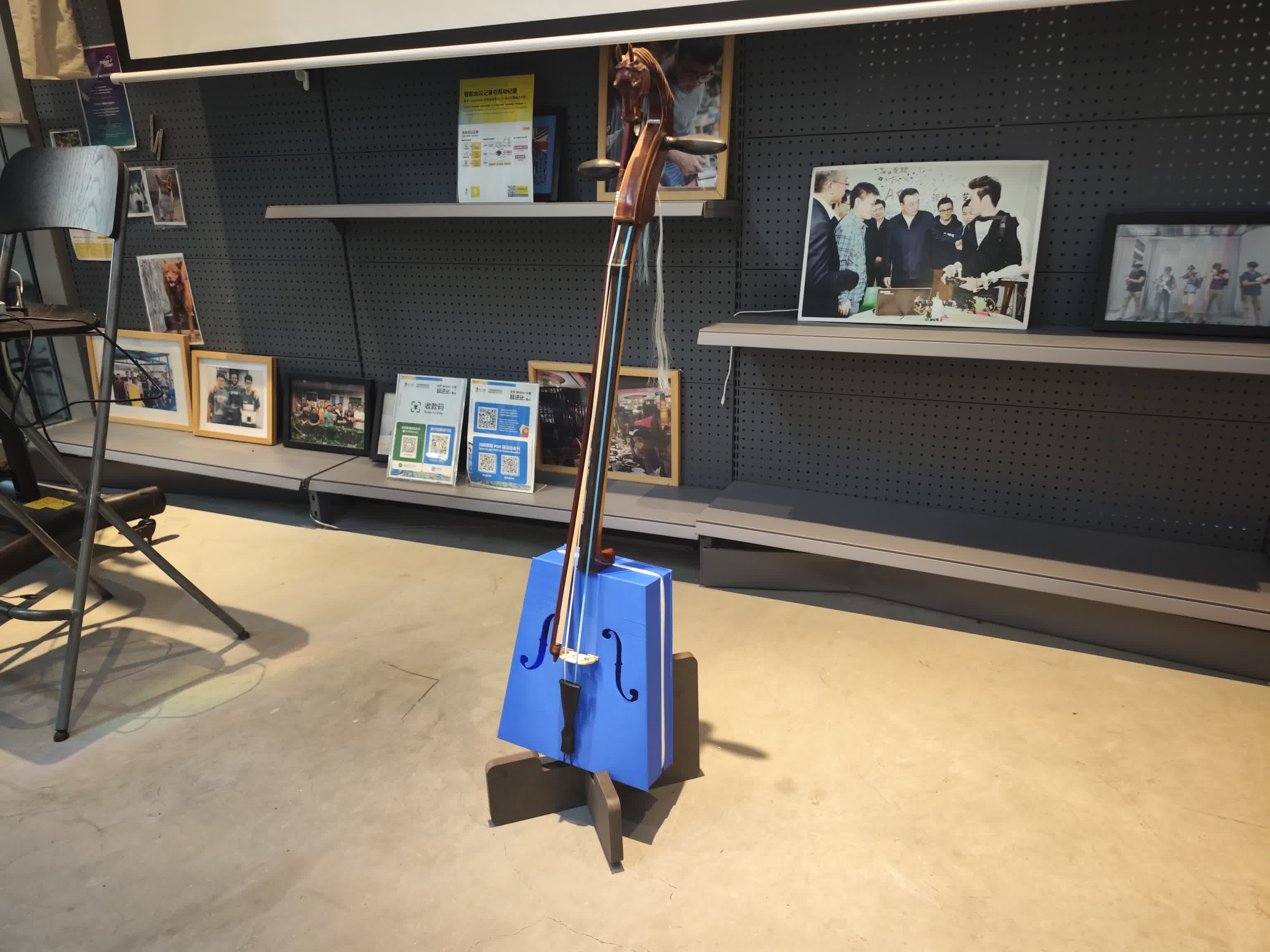
2D Stand Design & CNC Cutting
Since my fully assembled 3D-printed Morin Khuur is quite tall and top-heavy, simply resting it against a wall was unstable and risky. Designing and CNC-routing a custom, interlocking wooden stand became the perfect, practical addition to my project.
Design Concept & Stability
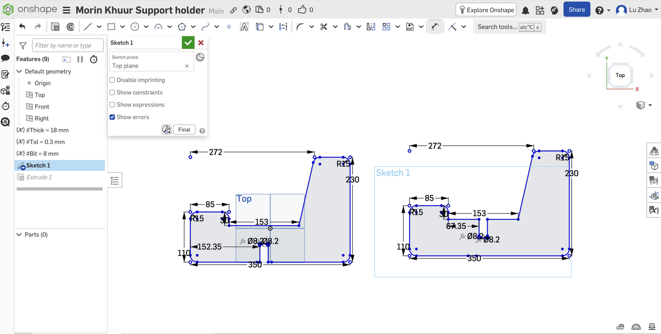
I designed a classic asymmetrical X-stand in Onshape using 18mm plywood. A symmetrical, vertical stand wouldn't work for such a top-heavy instrument. Instead, I designed the side profile to feature a 19-degree reclining backrest and extended rear base legs. This tilt naturally pushes the instrument's center of gravity backward, locking it safely into the V-shaped cradle without any risk of tipping forward.
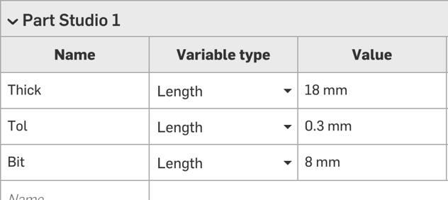
I designed the wooden stand for the Morin Khuur strictly using a parametric approach. Before drawing any geometry, I established global variables in the variable table, such as #Thickness = 18mm and #Tolerance = 0.3mm. The width of the interlocking slots was defined mathematically as #Thickness - #Tolerance.
-
#Thick= 18 mm (Plywood stock) -
#Tol= 0.3 mm (Joint clearance) -
#Bit= 8 mm (CNC end mill diameter)
I simply drafted the brief drawing without completely accurate dimensions on OnShape at the beginning, to have a clear view of the piece then adjust the dimension/degree accordingly.
Because an 8mm round CNC end-mill cannot cut sharp 90-degree inside corners, standard rectangular slots would prevent the interlocking boards from fitting together. To solve this physical limitation, I added Dogbone fillets to the bottom corners of all slots. I placed circles with an 8.2mm diameter exactly at the corner vertices.
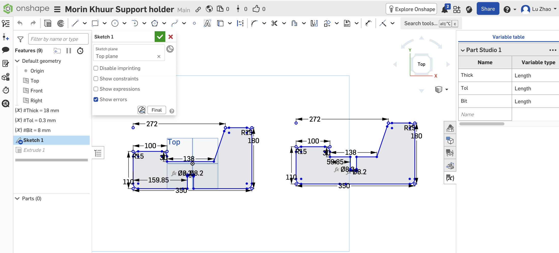
Calculating the True Seat Length
The most critical part of this X-stand is the seat clearance. The bottom of my 3D-printed soundbox is around 97mm thick. When two boards cross perpendicularly (at 90 degrees), the 2D seat cut on the board actually forms the hypotenuse of the resting space, while the physical thickness of the instrument acts as the leg of the triangle. I calculated the required 2D hypotenuse length for my 97.6mm gap:
Seat Length = 97.6 mm × 1.414 (√2) ≈ 138 mm
This is the minimum dimension, which still has risk of holding the Morin Khuur. Thus, I finally set the dimension of seat to 153mm. Also, the backseat height should be higher since Morin Khuur is tall, I need to ensure it is stable, so I enlarged the height from 180 to 230mm.
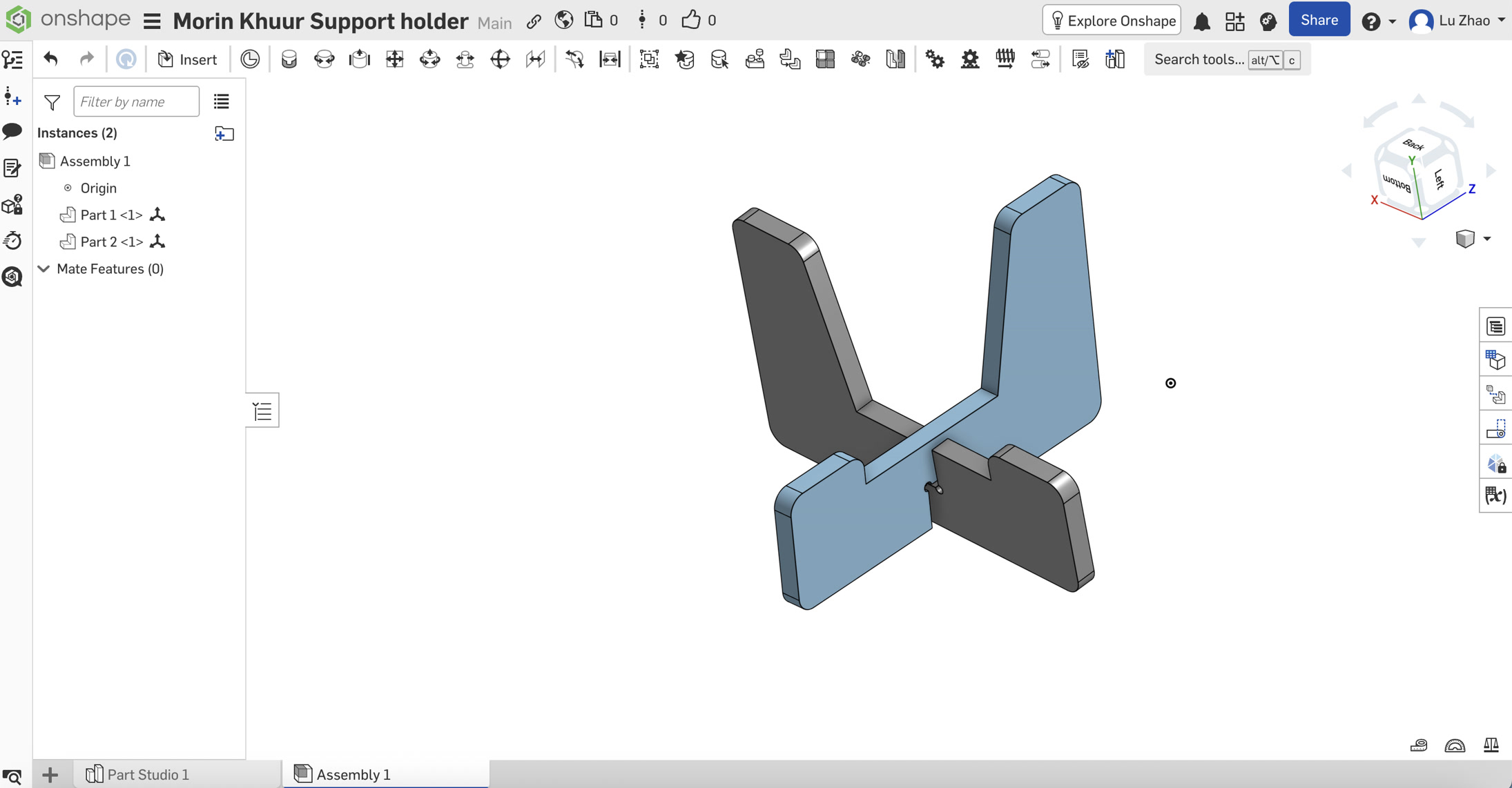
I checked briefly if they could fit together in Assembly before cutting.
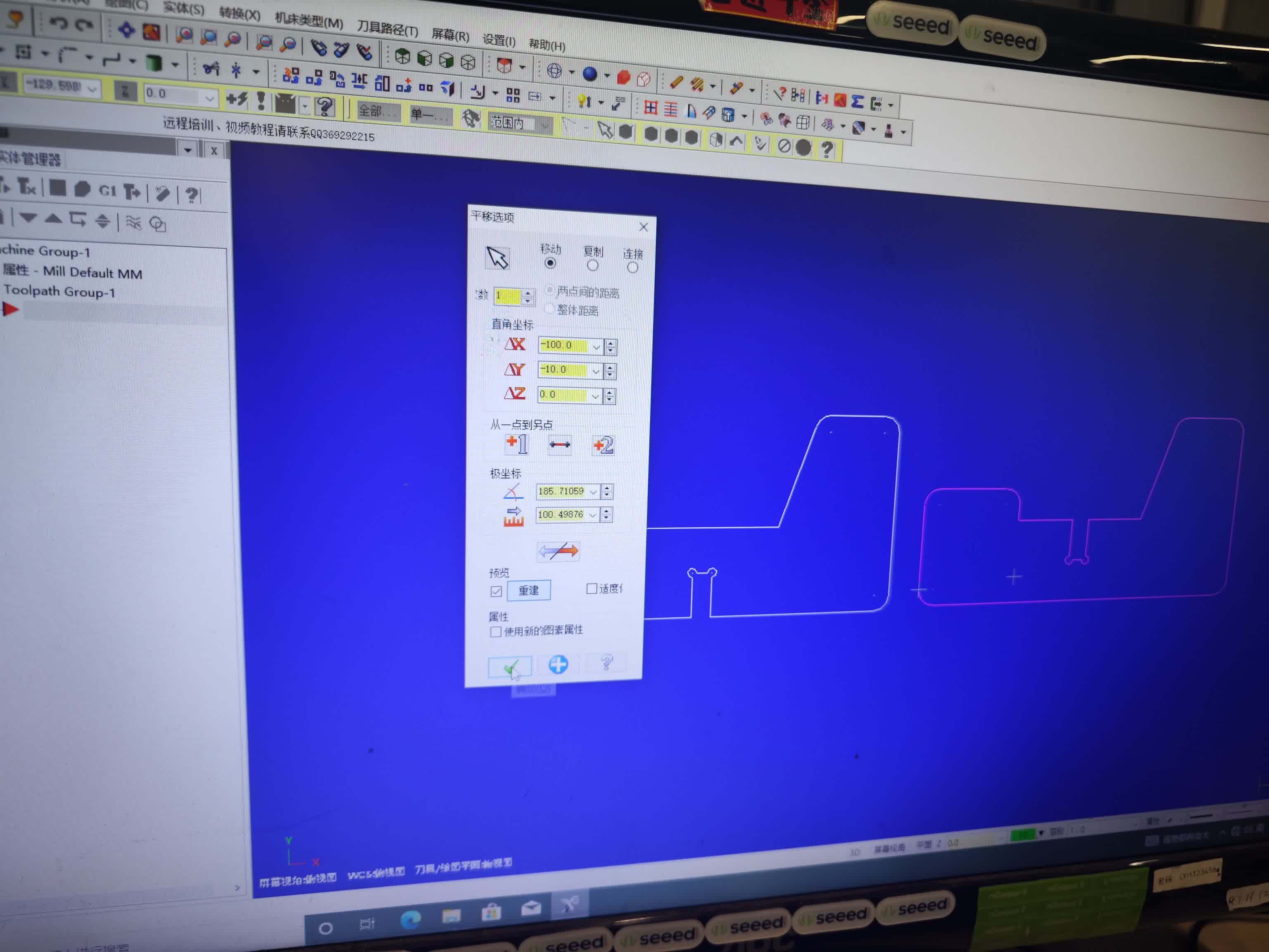
CNC Cutting
I adjusted the settings on Mastercam and generated the gcode.
After the CNC milling, I got these 2 boards.
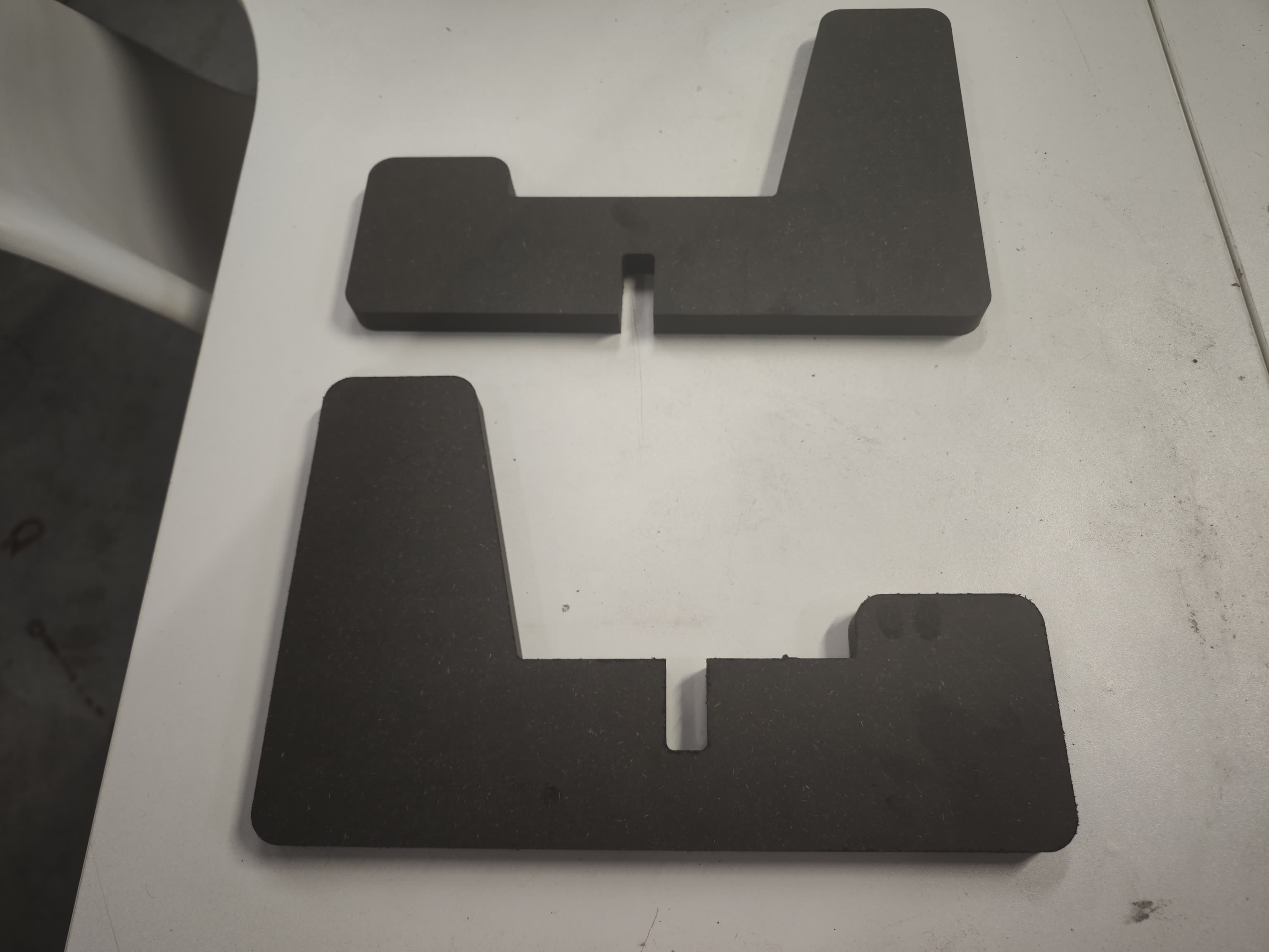
I assembled them through the slots in the middle of each board.
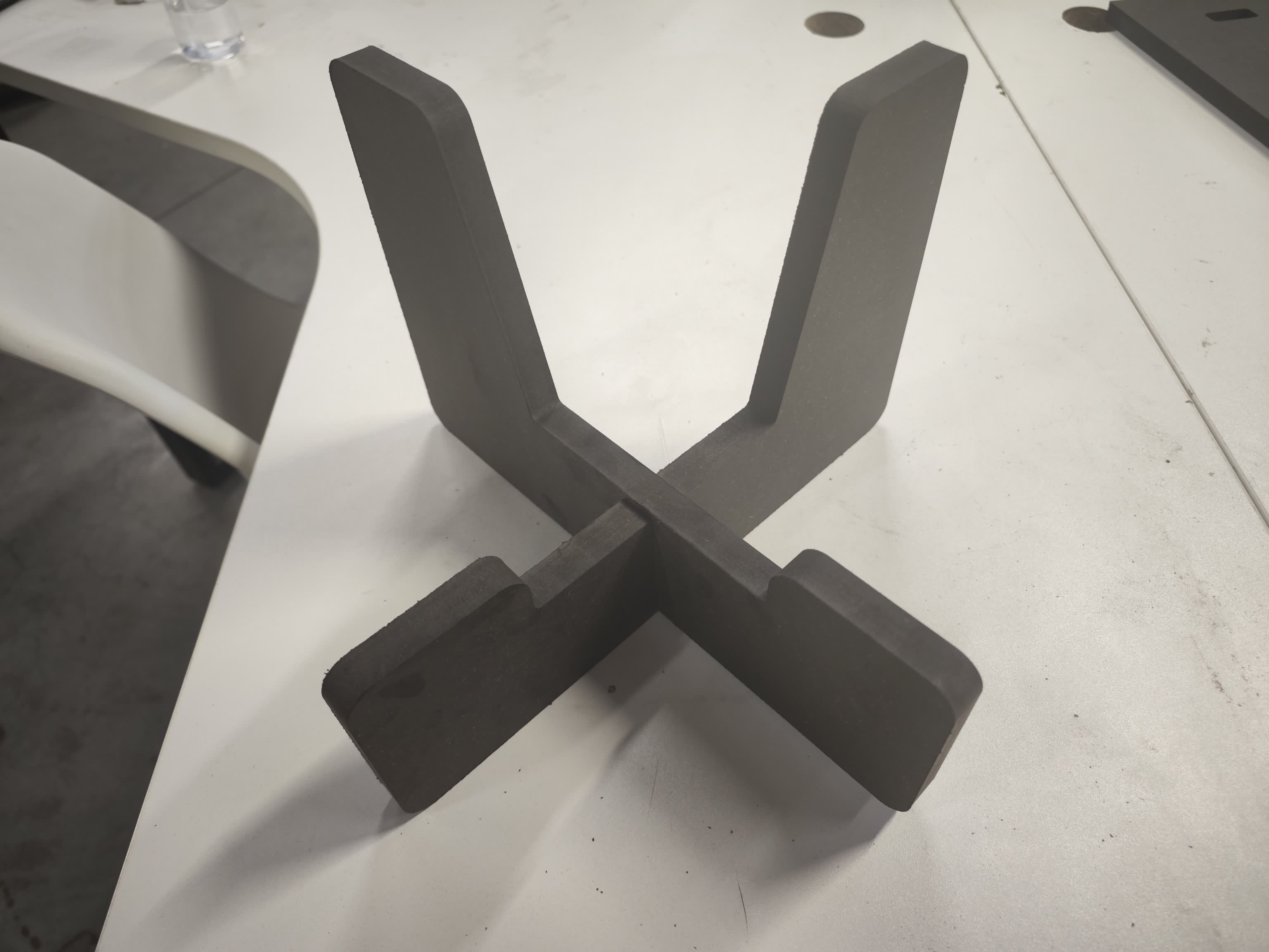
I put the Morin Khuur to sit on the stand. It is very steady.

Electronic Hardware & Coding
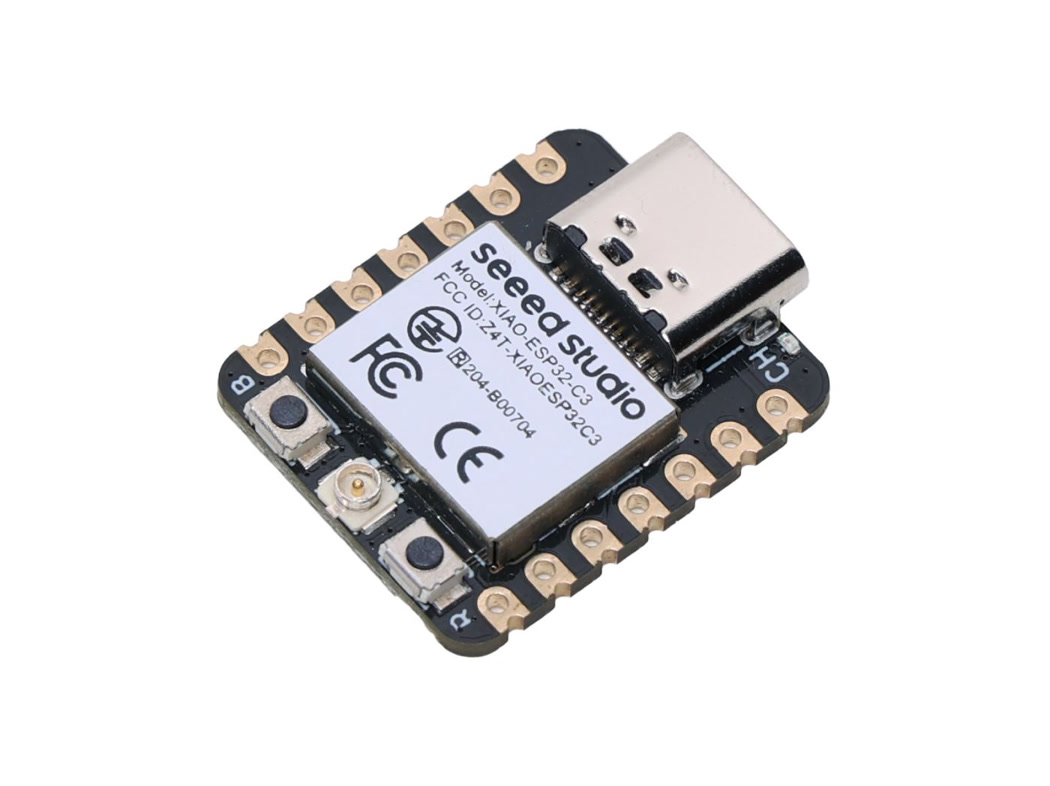
To transform the traditional Morin Khuur into a digital, sound-reactive instrument, I designed an embedded electronics system centered around the Seeed Studio XIAO ESP32C3. This microcontroller was chosen for its ultra-compact form factor, built-in Wi-Fi/Bluetooth, and powerful I2S audio processing capabilities. The interactive visual feedback is driven by a high-density 5V COB WS2812B LED Strip, which eliminates light spots for a smooth neon effect. For audio input, I integrated an INMP441 I2S Omnidirectional Digital Microphone to capture real-time acoustic data from the instrument's soundbox. Power is supplied by a 5V 2000mAh Li-Po Battery mounted on the removable back panel for easy access.
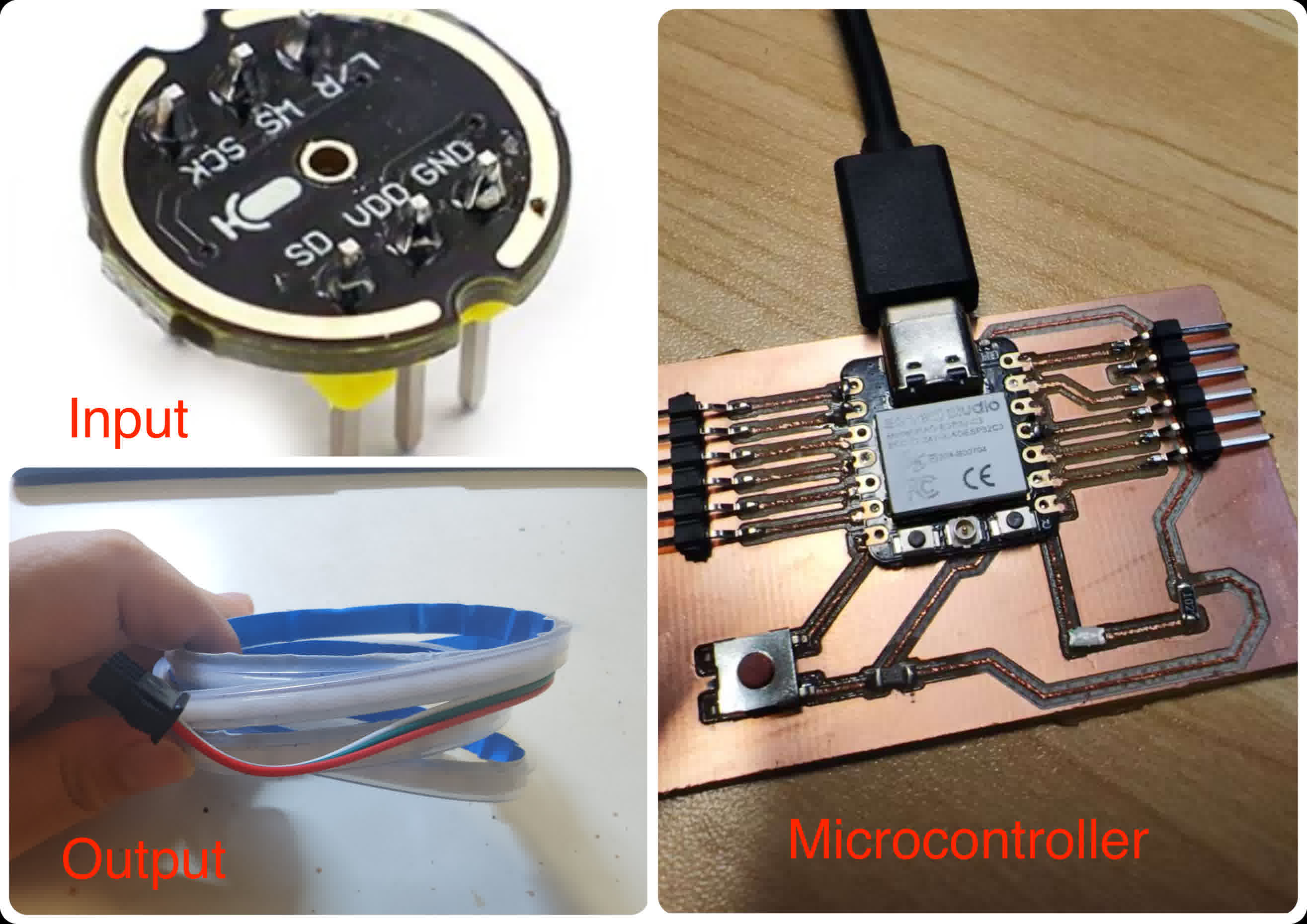
Main hardware composition:
-
Microcontroller: XIAO ESP32C3
-
Input: INMP441 Omnidirectional MEMS Microphone Module with I2S Interface
-
Output: 5V WS2812B COB RGB LED Strip - 8mm Wide, IP65 Waterproof, 160 LEDs/m
BOM (Bill of Materials) List:
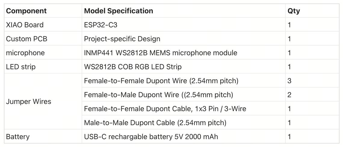
Microcontroller: XIAO ESP32-C3
Custom PCB:
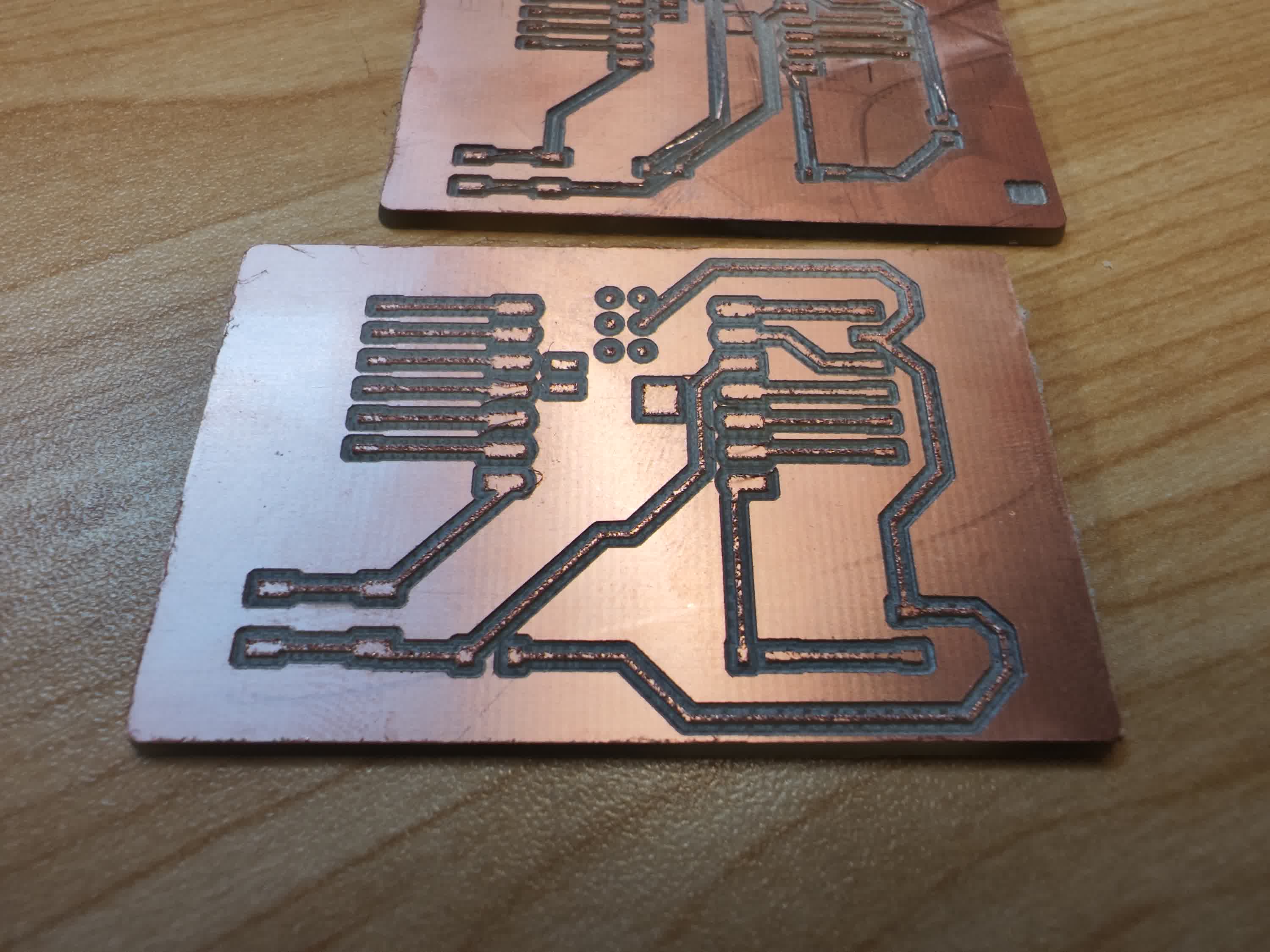
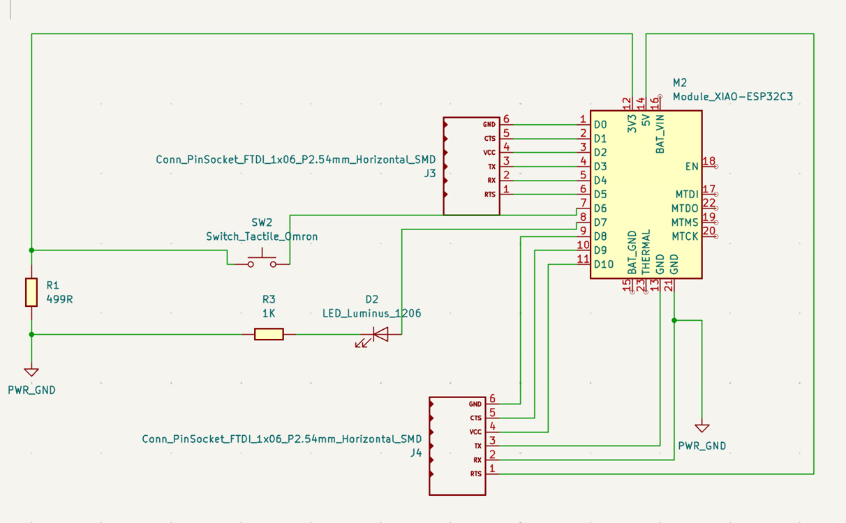
Circuit Schematic Design & PCB Diagram:
Refer to Week6 - Electronics Design | Lu Zhao | Fab Academy 2026 for more details.
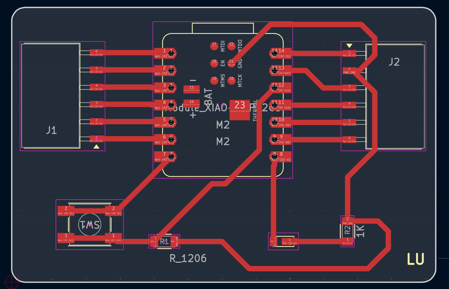
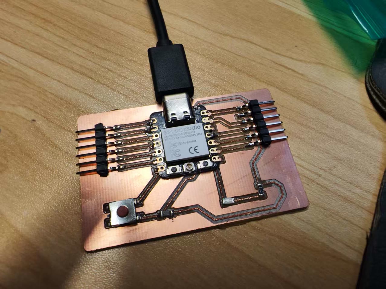
Integration of XIAO ESP32-C3 with custom PCB:
for production of custom PCB, refer to Week8 - Electronics Production | Lu Zhao | Fab Academy 2026
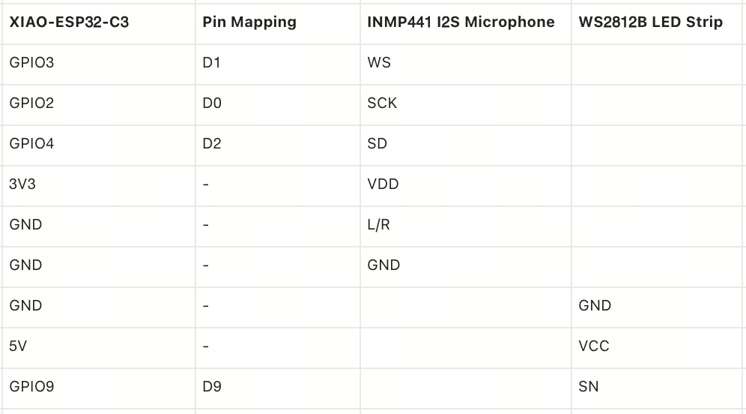
Circuit Connection, Pin Mapping
The wiring was carefully planned to utilize the pin matrix capabilities of the ESP32-C3 chip while strictly adhering to voltage safety limits.
For the lighting system, the LED strip's data line was connected directly to the D9 (GPIO 9) pin. The LED strip is a 5V component and it connects to XIAO 5V.
For the INMP441 I2S Microphone, precise routing and strict voltage control were critical. I mapped the connections as follows:
-
VDD to 3V3: This is an absolutely critical safety measure. The microphone operates strictly on a 1.8V - 3.3V logic level.
-
GND to GND: Standard power ground.
-
L/R to GND: Channel selection. Tying this pin to the ground configures the microphone to output data exclusively on the "Left Channel".
-
SCK to D0 (GPIO 2): Serial Clock (BCLK) for the I2S interface.
-
WS to D1 (GPIO 3): Word Select (LRCLK) to dictate the data channel timing.
-
SD to D2 (GPIO 4): Serial Data (DIN) output carrying the captured audio signal to the microcontroller.
Main components for circuit
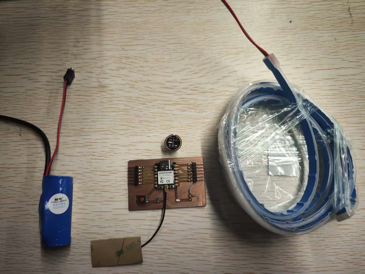
I used the dupont cables to connect all electronic parts together.
Testing the LED Strip on Arduino IDE
Testing Logic: To verify the data transmission between the XIAO ESP32C3 and the WS2812B LED strip, I designed a minimal power-consumption test script. Instead of illuminating the entire strip simultaneously, the code creates a "single shooting star" effect where only one pixel lights up in cyan per frame.
Hardware Safety Precautions: The most critical engineering consideration during this initial test was power management. Since the microcontroller and the LED strip were powered directly via the computer's USB port, lighting up a high-density COB LED strip at full capacity could draw excessive current and permanently damage the computer's motherboard. To prevent this, I implemented two strict software-level safety locks: illuminating only one LED pixel at a time, and hardcoding a global brightness limit of 15 (out of a maximum of 255). This guarantees the current draw remains well within the standard USB safety limits while still providing clear visual debugging feedback.
Testing Code:
#include <Adafruit_NeoPixel.h>

// --- Hardware Parameters ---
#define PIN        9   // XIAO's D9 pin is directly mapped to 9 in code
#define NUMPIXELS  30  // Testing phase: Only controlling the first 30 LEDs

// Initialize NeoPixel strip object
Adafruit_NeoPixel strip(NUMPIXELS, PIN, NEO_GRB + NEO_KHZ800);

void setup() {
  // Start serial communication for debugging
  Serial.begin(115200);
  Serial.println("Safety test mode initialized...");

  strip.begin();           // Initialize the LED strip

  // ⚠️ Core Safety Lock: Brightness limited to 15 (max 255).
  // This ensures it is absolutely safe to draw power directly from the computer USB!
  strip.setBrightness(15);

  strip.show();            // Update strip (ensures the initial state is all off)
}

void loop() {
  // Visual effect: Cyberpunk Cyan "Single Shooting Star"
  // Only one LED is lit per frame, which is extremely power-efficient
  for(int i = 0; i < strip.numPixels(); i++) {
    strip.clear(); // Clear the previous frame's color (turn all off)

    // Set the i-th LED to Cyan (Red: 0, Green: 255, Blue: 255)
    strip.setPixelColor(i, strip.Color(0, 255, 255));

    strip.show();  // Send updated data to the strip to light it up
    delay(50);     // Pause for 50 milliseconds to control the speed of the star
  }
}
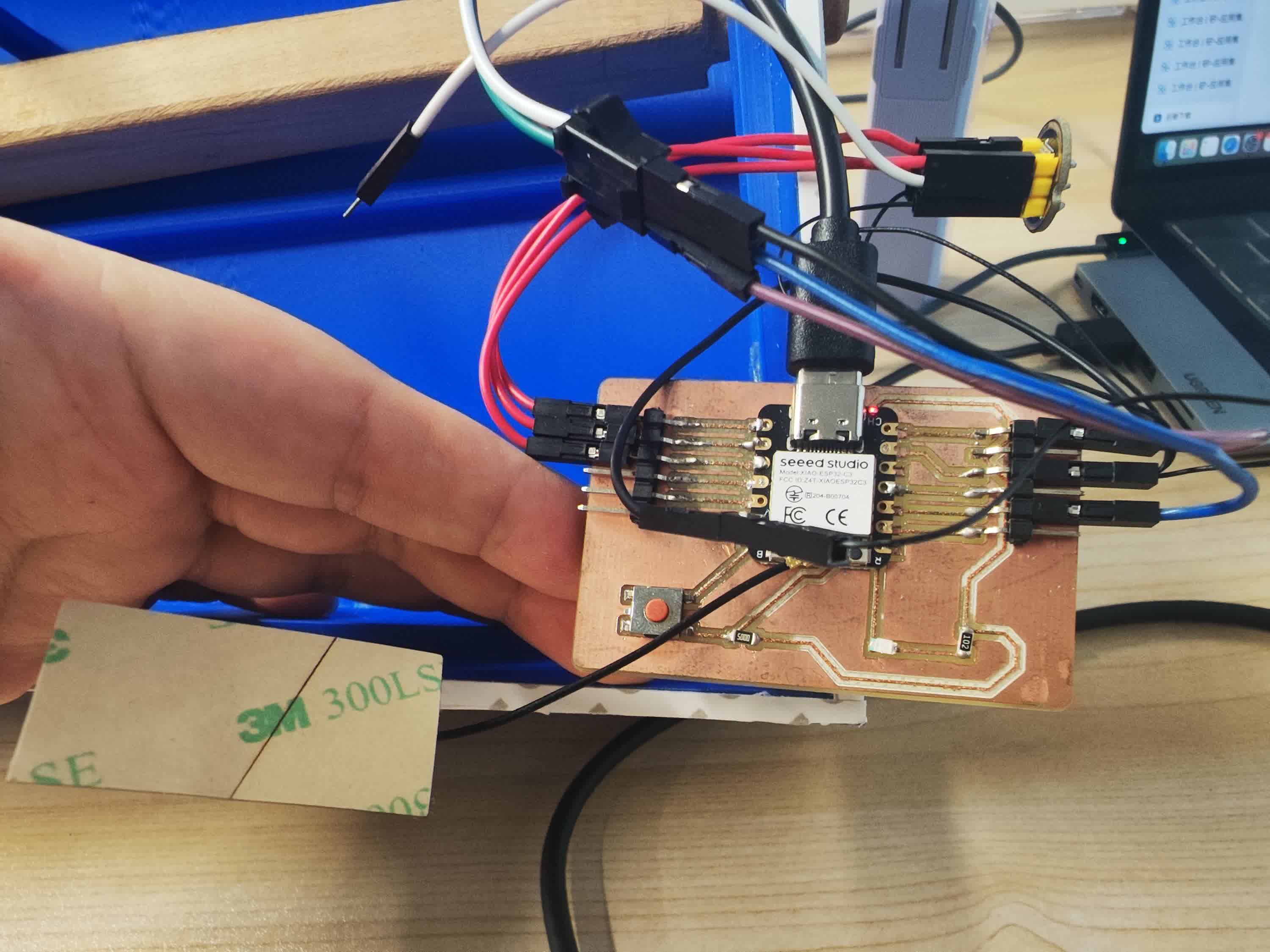
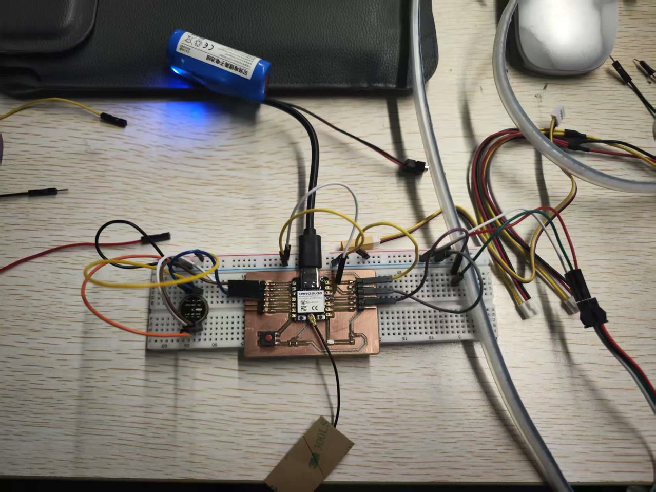
Testing the whole circuit on Breadboard
For the initial testing of my final project, I used jumper wires and breadboard to connect a XIAO ESP32C3, an INMP441 microphone module, and a 5V COB LED strip to verify whether the circuit could run properly.
Software Logic & Fast Fourier Transform (FFT)
To create a meaningful interaction between the acoustic sound and the digital light, I implemented a Fast Fourier Transform (FFT) algorithm using the arduinoFFT library. Instead of simply blinking to the volume, the software reads the 32-bit audio data via the I2S pins, cleans it, and maps it across different frequency bands.
The visual output is highly dynamic: the volume amplitude determines the length of the LED light column (spreading outward from the center), while the frequency (pitch) dictates the color. For instance, low-frequency bass notes trigger warm red colors, mid-range vocals trigger greens, and high-frequency overtones trigger bright blue flashes. During the testing phase, I hardcoded a brightness limit of 20 (out of 255) in the firmware to protect the computer's USB port from overcurrent.
Code:
#include <Adafruit_NeoPixel.h>
#include <driver/i2s.h>
#include "arduinoFFT.h"

// ================= Hardware Pin Configuration =================
// 1. LED Strip Configuration
#define LED_PIN     9      // XIAO D9 Pin
#define NUMPIXELS   160     // Number of LEDs on your strip
Adafruit_NeoPixel strip(NUMPIXELS, LED_PIN, NEO_GRB + NEO_KHZ800);

// 2. Microphone I2S Pin Configuration (Adapted for XIAO ESP32C3)
#define I2S_PORT    I2S_NUM_0
#define I2S_SCK     D0      // XIAO D0 Pin
#define I2S_WS      D1      // XIAO D1 Pin
#define I2S_SD      D2      // XIAO D2 Pin

// ================= FFT Audio Processing Parameters =================
const uint16_t samples = 256;           // Number of samples, must be a power of 2
const double samplingFrequency = 16000; // Sampling frequency 16kHz (Sufficient for main musical frequency bands)
double vReal[samples];                  // Real part array
double vImag[samples];                  // Imaginary part array

// Initialize FFT object
ArduinoFFT<double> FFT = ArduinoFFT<double>(vReal, vImag, samples, samplingFrequency);

void setup() {
  Serial.begin(115200);

  // 1. Initialize LED strip
  strip.begin();
  strip.setBrightness(20); // ⚠️ Safety Lock: Limit brightness to prevent USB overload
  strip.clear();
  strip.show();

  // 2. Configure I2S Microphone
  i2s_config_t i2s_config = {
    .mode = (i2s_mode_t)(I2S_MODE_MASTER | I2S_MODE_RX),
    .sample_rate = samplingFrequency,
    .bits_per_sample = I2S_BITS_PER_SAMPLE_32BIT, // INMP441 typically outputs 32 or 24 bits
    .channel_format = I2S_CHANNEL_FMT_ONLY_LEFT,  // Left channel
    .communication_format = I2S_COMM_FORMAT_STAND_I2S,
    .intr_alloc_flags = ESP_INTR_FLAG_LEVEL1,
    .dma_buf_count = 8,
    .dma_buf_len = 64,
    .use_apll = false
  };

  i2s_pin_config_t pin_config = {
    .bck_io_num = I2S_SCK,
    .ws_io_num = I2S_WS,
    .data_out_num = I2S_PIN_NO_CHANGE,
    .data_in_num = I2S_SD
  };

  // Install and start I2S driver
  i2s_driver_install(I2S_PORT, &i2s_config, 0, NULL);
  i2s_set_pin(I2S_PORT, &pin_config);

  Serial.println("Microphone initialization complete. Listening...");
}

void loop() {
  // 1. Capture Audio Data
  size_t bytesIn = 0;
  int32_t sampleBuffer[samples];

  // Read audio data from microphone into Buffer
  i2s_read(I2S_PORT, &sampleBuffer, sizeof(sampleBuffer), &bytesIn, portMAX_DELAY);

  int samplesRead = bytesIn / sizeof(int32_t);
  double totalVolume = 0;

  // 2. Data Cleaning: Convert 32-bit raw data to floating-point numbers for FFT processing
  for (int i = 0; i < samplesRead; i++) {
    // Bit-shift 32-bit data to scale, denoise, and calculate total absolute volume
    int16_t audioValue = sampleBuffer[i] >> 14;
    vReal[i] = audioValue;
    vImag[i] = 0.0; // Clear imaginary part
    totalVolume += abs(audioValue);
  }

  // Calculate average volume (used to control the number of lit LEDs)
  int averageVolume = totalVolume / samplesRead;

  // 3. Execute Fast Fourier Transform (FFT)
  FFT.windowing(FFT_WIN_TYP_HAMMING, FFT_FORWARD); // Apply Windowing to reduce noise leakage
  FFT.compute(FFT_FORWARD);                        // Compute frequency domain
  FFT.complexToMagnitude();                        // Compute magnitudes of frequencies

  // 4. Analyze Frequency Band Energy (Calculate Bass, Mid, and Treble ratios)
  long bassEnergy = 0, midEnergy = 0, trebleEnergy = 0;
  for (int i = 2; i < (samplesRead / 2); i++) { // Skip DC component
    if (i < 10) bassEnergy += vReal[i];            // Approx. 100-600Hz (Bass / Drum beats)
    else if (i < 40) midEnergy += vReal[i];        // Approx. 600-2500Hz (Mid-range / Vocals)
    else trebleEnergy += vReal[i];                 // Approx. 2500Hz+ (Treble / Instrument overtones)
  }

  // 5. Map Data to the LED Strip
  strip.clear();

  // If the environment is too quiet (background noise), do not light up
  if (averageVolume > 200) {
    // Determine the number of LEDs to light based on volume (expanding from the center)
    // Map: Volume 200~5000 to 1~15 LEDs (half strip)
    int ledsToLight = map(averageVolume, 200, 5000, 1, NUMPIXELS / 2);
    if (ledsToLight > NUMPIXELS / 2) ledsToLight = NUMPIXELS / 2;

    // Determine main color based on frequency band energy
    int r = map(bassEnergy, 0, 50000, 0, 255);
    int g = map(midEnergy, 0, 30000, 0, 255);
    int b = map(trebleEnergy, 0, 20000, 0, 255);

    // Constrain color values within the valid 0-255 range
    r = constrain(r, 0, 255);
    g = constrain(g, 0, 255);
    b = constrain(b, 0, 255);

    // Draw symmetrical volume columns from the center outwards
    int center = NUMPIXELS / 2;
    for (int i = 0; i < ledsToLight; i++) {
      // Apply the combined RGB colors symmetrically
      strip.setPixelColor(center + i, strip.Color(r, g, b));
      strip.setPixelColor(center - 1 - i, strip.Color(r, g, b));
    }
  }

  strip.show();
}
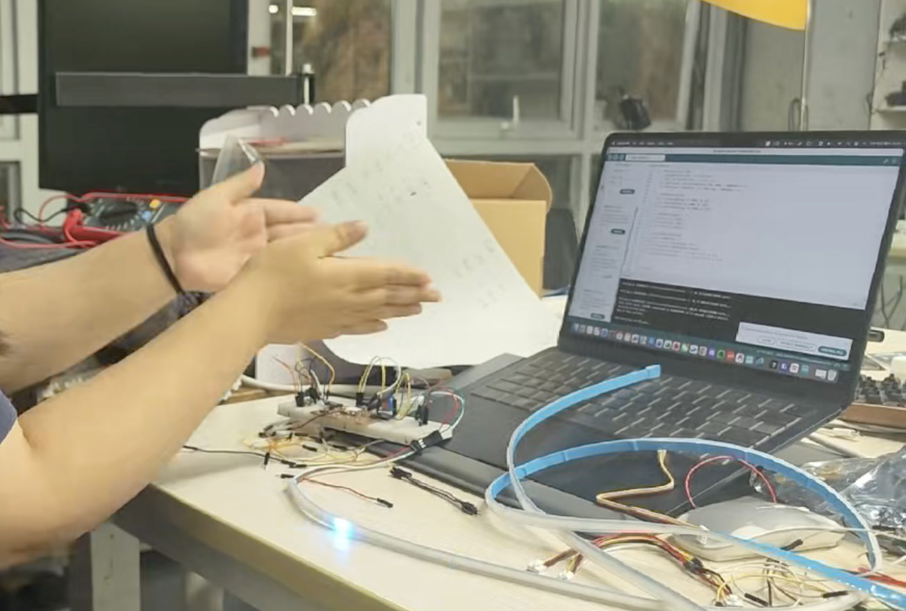
Simply clapped to test the effect after uploading the code, it lighted up when I clapped, and if the volume went higher, the light turned blue.
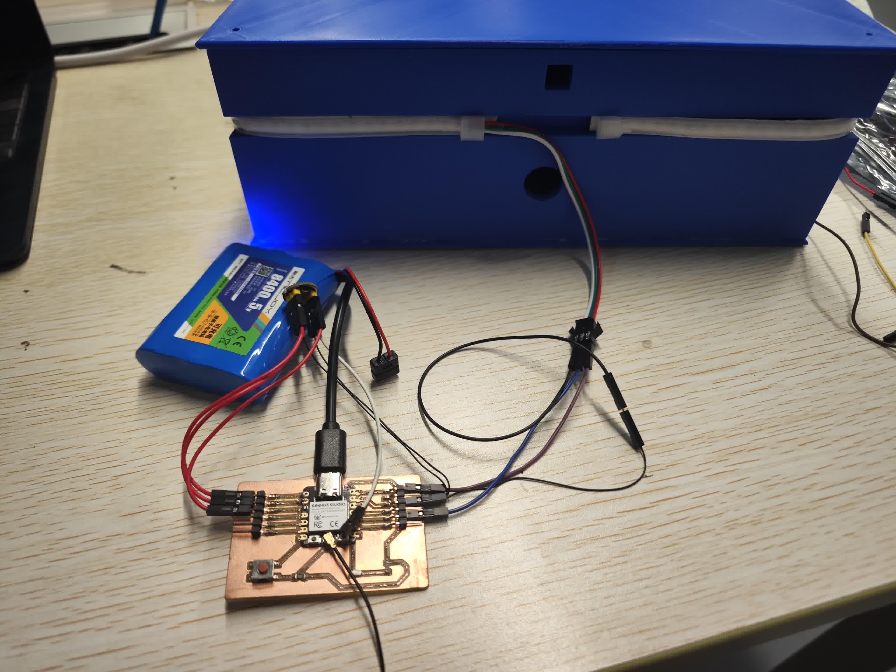
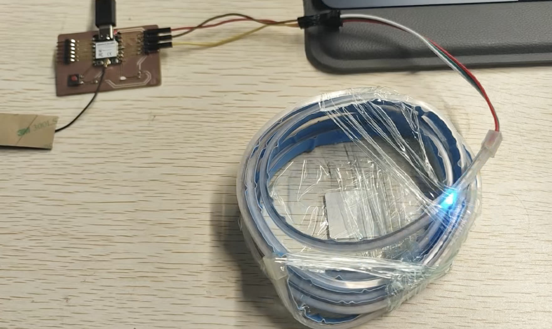
Direct Wiring & Functional Verification
Following successful validation on the breadboard, I proceeded to eliminate the prototyping board to test a more compact setup. I established direct point-to-point connections between the XIAO ESP32C3, the INMP441 microphone, and the LED strip using DuPont jumper wires. A subsequent system test confirmed that the hardware continued to execute the FFT audio-reactive code flawlessly. This step successfully verified the stability of the circuit logic and signal transmission before the final physical integration into the instrument's soundbox.
Web-Based Audio Visualizer using WebSocket and p5.js
While the local Processing application worked perfectly, I wanted to elevate the project by making the dashboard accessible via any standard web browser. This required an architectural shift. Standard web browsers cannot directly receive raw UDP packets due to security protocols. To bridge the gap between the microcontroller and the browser, I upgraded the ESP32C3 to act as a WebSocket Server. WebSocket provides a persistent, low-latency, full-duplex communication channel over a single TCP connection, which is the industry standard for real-time web applications.
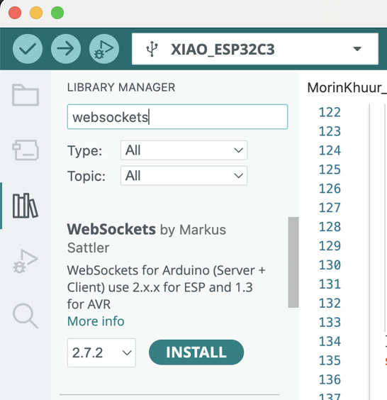
Hardware Implementation (ESP32C3 WebSocket Server)
I utilized the WebSocketsServer library by Markus Sattler. The ESP32C3 now opens port 81 and waits for incoming connections from a web client. To ensure the generative art animation on the web runs smoothly without the stuttering issues I encountered earlier, I optimized the data transmission rate. I set the broadcast interval to 20 milliseconds, which means the ESP32 pushes data at 50 FPS. This perfectly synchronizes the hardware sampling with the browser's rendering cycle.
Arduino WebSocket Sender Code:
#include <Adafruit_NeoPixel.h>
#include <driver/i2s.h>
#include "arduinoFFT.h"
#include <WiFi.h>
#include <WebSocketsServer.h>

// ================= 1. Network Configuration =================
// Replace with your actual Wi-Fi hotspot credentials
const char* ssid = "Xiaomi 12S Ultra";
const char* password = "13572468";

// Start WebSocket server on port 81
WebSocketsServer webSocket = WebSocketsServer(81);

unsigned long lastSendTime = 0;
// Set transmission interval to 20ms (~50 FPS) for buttery smooth visuals
const int sendInterval = 20;

// ================= 2. Hardware & FFT Configuration =================
#define LED_PIN     9
#define NUMPIXELS   160
Adafruit_NeoPixel strip(NUMPIXELS, LED_PIN, NEO_GRB + NEO_KHZ800);

#define I2S_PORT    I2S_NUM_0
#define I2S_SCK     D0
#define I2S_WS      D1
#define I2S_SD      D2

const uint16_t samples = 256;
const double samplingFrequency = 16000;
double vReal[samples];
double vImag[samples];
ArduinoFFT<double> FFT = ArduinoFFT<double>(vReal, vImag, samples, samplingFrequency);

void setup() {
  Serial.begin(115200);

  // Initialize Wi-Fi Connection
  Serial.print("Connecting to Wi-Fi...");
  WiFi.begin(ssid, password);
  while (WiFi.status() != WL_CONNECTED) {
    delay(500);
    Serial.print(".");
  }
  Serial.println("\nWiFi Connected!");

  // CRITICAL: Print the ESP32 IP address. You need this for the HTML file!
  Serial.print("ESP32 IP Address: ");
  Serial.println(WiFi.localIP());

  // Initialize WebSocket Server
  webSocket.begin();

  // Initialize NeoPixel LED Strip
  strip.begin();
  strip.setBrightness(20);
  strip.clear();
  strip.show();

  // Configure I2S Microphone
  i2s_config_t i2s_config = {
    .mode = (i2s_mode_t)(I2S_MODE_MASTER | I2S_MODE_RX),
    .sample_rate = samplingFrequency,
    .bits_per_sample = I2S_BITS_PER_SAMPLE_32BIT,
    .channel_format = I2S_CHANNEL_FMT_ONLY_LEFT,
    .communication_format = I2S_COMM_FORMAT_STAND_I2S,
    .intr_alloc_flags = ESP_INTR_FLAG_LEVEL1,
    .dma_buf_count = 8,
    .dma_buf_len = 64,
    .use_apll = false
  };
  i2s_pin_config_t pin_config = {
    .bck_io_num = I2S_SCK,
    .ws_io_num = I2S_WS,
    .data_out_num = I2S_PIN_NO_CHANGE,
    .data_in_num = I2S_SD
  };
  i2s_driver_install(I2S_PORT, &i2s_config, 0, NULL);
  i2s_set_pin(I2S_PORT, &pin_config);
}

void loop() {
  // Keep WebSocket connection alive
  webSocket.loop();

  // 1. Capture Audio Data
  size_t bytesIn = 0;
  int32_t sampleBuffer[samples];
  i2s_read(I2S_PORT, &sampleBuffer, sizeof(sampleBuffer), &bytesIn, portMAX_DELAY);

  int samplesRead = bytesIn / sizeof(int32_t);
  double totalVolume = 0;

  // 2. Data Cleaning
  for (int i = 0; i < samplesRead; i++) {
    int16_t audioValue = sampleBuffer[i] >> 14;
    vReal[i] = audioValue;
    vImag[i] = 0.0;
    totalVolume += abs(audioValue);
  }

  int averageVolume = totalVolume / samplesRead;

  // 3. Execute Fast Fourier Transform (FFT)
  FFT.windowing(FFT_WIN_TYP_HAMMING, FFT_FORWARD);
  FFT.compute(FFT_FORWARD);
  FFT.complexToMagnitude();

  // 4. Analyze Frequency Band Energy
  long bassEnergy = 0, midEnergy = 0, trebleEnergy = 0;
  for (int i = 2; i < (samplesRead / 2); i++) {
    if (i < 10) bassEnergy += vReal[i];
    else if (i < 40) midEnergy += vReal[i];
    else trebleEnergy += vReal[i];
  }

  int r = 0, g = 0, b = 0;
  strip.clear();

  // 5. Map Data to the LED Strip (Using tuned HDR parameters)
  if (averageVolume > 400) {
    int ledsToLight = map(averageVolume, 400, 8000, 1, NUMPIXELS / 2);
    if (ledsToLight > NUMPIXELS / 2) ledsToLight = NUMPIXELS / 2;

    r = map(bassEnergy, 0, 50000, 0, 255);
    g = map(midEnergy, 0, 30000, 0, 255);
    b = map(trebleEnergy, 0, 20000, 0, 255);

    r = constrain(r, 0, 255);
    g = constrain(g, 0, 255);
    b = constrain(b, 0, 255);

    int center = NUMPIXELS / 2;
    for (int i = 0; i < ledsToLight; i++) {
      strip.setPixelColor(center + i, strip.Color(r, g, b));
      strip.setPixelColor(center - 1 - i, strip.Color(r, g, b));
    }
  }
  strip.show();

  // 6. Broadcast Data via WebSocket
  unsigned long currentTime = millis();
  if (currentTime - lastSendTime >= sendInterval) {
    lastSendTime = currentTime;

    // Construct data packet: "R,G,B"
    String dataString = String(r) + "," + String(g) + "," + String(b);

    // Broadcast text to all connected HTML clients
    webSocket.broadcastTXT(dataString);
  }
}
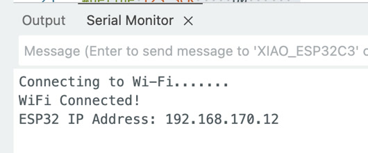
I copied the ESP32 IP address from Serial Monitor which will be used for the HTML & JS receiver code.
ESP32 IP Address: 192.168.170.12
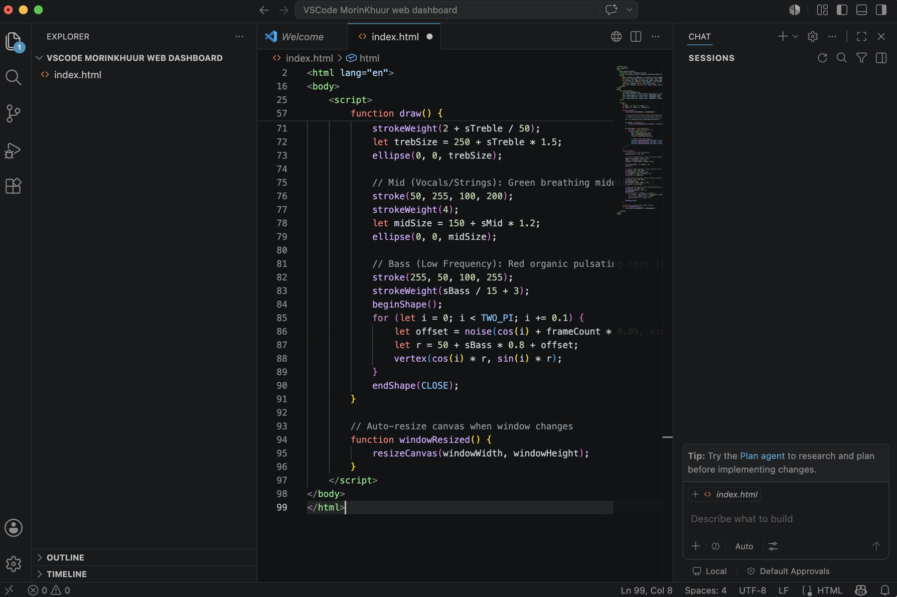
Development Environment & Workflow (VS Code)
To develop the frontend interface, I shifted from the Arduino IDE to Visual Studio Code (VS Code). It's my first time using VS Code, I downloaded it from the website.
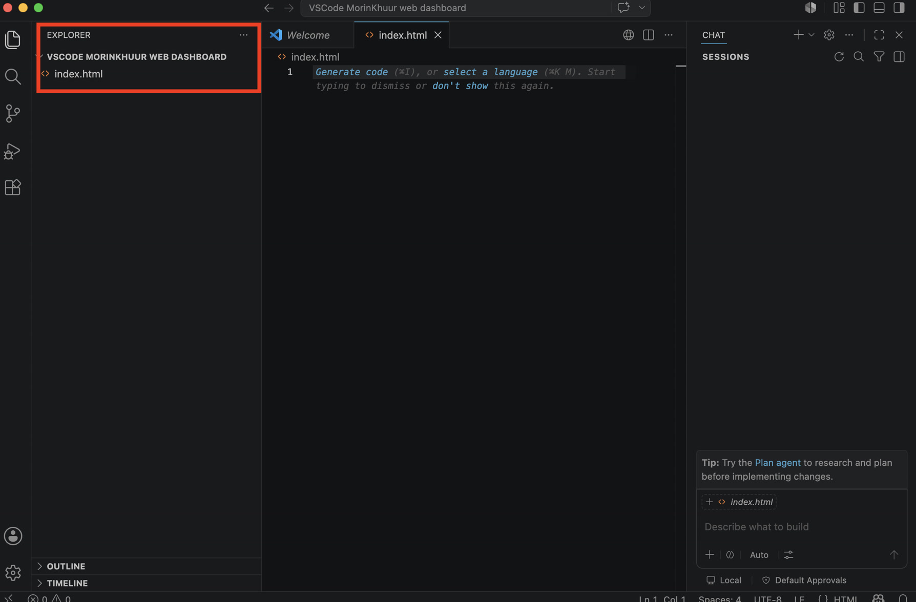
I created a dedicated project directory and initialized an index.html file. VS Code provided an environment for writing and formatting both the HTML structure and the embedded JavaScript (p5.js) logic.
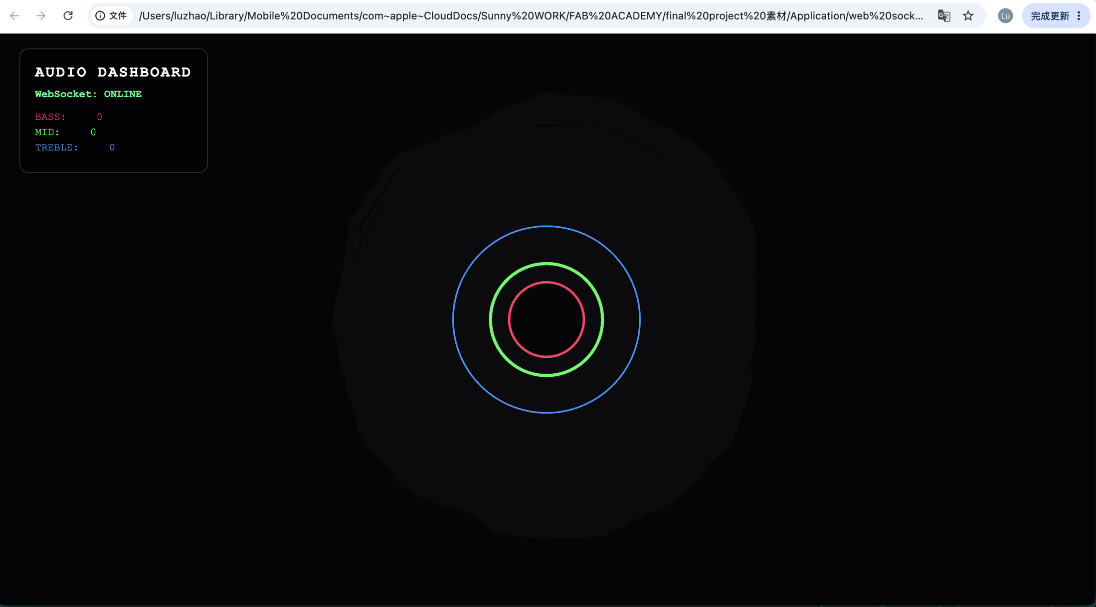
Software Implementation (HTML UI & p5.js Generative Art)
For the web client, I combined standard HTML/CSS with the p5.js library to build an "Audio Mandala".
-
The HUD Overlay: An HTML
<div>acts as a cyber-punk style Head-Up Display in the top-left corner. It parses the incoming WebSocket string and updates the exact Bass, Mid, and Treble numerical values dynamically. -
The p5.js Canvas: Instead of simple bar charts, I used generative art algorithms to visualize the sound. The high frequencies (Treble) drive a reactive outer blue ring, the vocal range (Mid) drives a breathing green ring, and the low frequencies (Bass) drive a pulsating red core.
-
Algorithmic Beauty: I utilized the
lerp()function to smooth out the incoming data, giving the visuals a natural damping effect. For the red bass core, I implementednoise()(Perlin Noise) on a circular path. This distorts the perfect circle into an organic, amoeba-like shape that physically reacts to the beats of the Morin Khuur, creating an incredibly immersive connection between the traditional instrument and the digital browser.
HTML & JS Receiver Code:
I used the ESP32 address above to fill in the line 36.
<!DOCTYPE html>
<html lang="en">
<head>
    <meta charset="UTF-8">
    <title>Morin Khuur Dashboard</title>
    <script src="https://cdnjs.cloudflare.com/ajax/libs/p5.js/1.6.0/p5.js"></script>
    <style>
        body { margin: 0; padding: 0; overflow: hidden; background-color: #08080A; font-family: 'Courier New', Courier, monospace; color: white;}
        #ui-layer { position: absolute; top: 20px; left: 30px; z-index: 10; background: rgba(0,0,0,0.6); padding: 20px; border-radius: 12px; border: 1px solid #333;}
        h1 { margin: 0 0 10px 0; font-size: 20px; letter-spacing: 2px; }
        .status { color: #00FF88; font-weight: bold; margin-bottom: 15px; font-size: 14px;}
        .data-row { margin: 5px 0; font-size: 14px;}
        span.val { display: inline-block; width: 40px; text-align: right; }
    </style>
</head>
<body>
    <div id="ui-layer">
        <h1>AUDIO DASHBOARD</h1>
        <div class="status" id="ws-status">Connecting to Instrument...</div>
        <div class="data-row" style="color: #FF3366;">BASS:   <span class="val" id="val-bass">0</span></div>
        <div class="data-row" style="color: #33FF66;">MID:    <span class="val" id="val-mid">0</span></div>
        <div class="data-row" style="color: #3399FF;">TREBLE: <span class="val" id="val-treb">0</span></div>
    </div>

    <script>
        let ws;
        let bass = 0, mid = 0, treble = 0;
        let sBass = 0, sMid = 0, sTreble = 0;

        function setup() {
            createCanvas(windowWidth, windowHeight);

            // =========================================================
            // REPLACE 192.168.X.X WITH YOUR ACTUAL ESP32 IP ADDRESS
            // =========================================================
            ws = new WebSocket("ws://192.168.170.12:81/");

            ws.onopen = function() {
                document.getElementById('ws-status').innerText = "WebSocket: ONLINE";
            };

            ws.onmessage = function(event) {
                let vals = event.data.split(',');
                if(vals.length === 3) {
                    bass = parseFloat(vals[0]);
                    mid = parseFloat(vals[1]);
                    treble = parseFloat(vals[2]);

                    // Update HTML DOM elements
                    document.getElementById('val-bass').innerText = Math.round(bass);
                    document.getElementById('val-mid').innerText = Math.round(mid);
                    document.getElementById('val-treb').innerText = Math.round(treble);
                }
            };
        }

        function draw() {
            // Motion blur effect background
            background(8, 8, 10, 40);

            // Linear interpolation (lerp) for buttery smooth visual transitions
            sBass = lerp(sBass, bass, 0.15);
            sMid = lerp(sMid, mid, 0.15);
            sTreble = lerp(sTreble, treble, 0.15);

            translate(width / 2, height / 2);
            noFill();

            // Treble (High Frequency): Blue reactive outer ring
            stroke(50, 150, 255, 200);
            strokeWeight(2 + sTreble / 50);
            let trebSize = 250 + sTreble * 1.5;
            ellipse(0, 0, trebSize);

            // Mid (Vocals/Strings): Green breathing middle ring
            stroke(50, 255, 100, 200);
            strokeWeight(4);
            let midSize = 150 + sMid * 1.2;
            ellipse(0, 0, midSize);

            // Bass (Low Frequency): Red organic pulsating core (using Perlin Noise)
            stroke(255, 50, 100, 255);
            strokeWeight(sBass / 15 + 3);
            beginShape();
            for (let i = 0; i < TWO_PI; i += 0.1) {
                let offset = noise(cos(i) + frameCount * 0.05, sin(i) + frameCount * 0.05) * sBass;
                let r = 50 + sBass * 0.8 + offset;
                vertex(cos(i) * r, sin(i) * r);
            }
            endShape(CLOSE);
        }

        // Auto-resize canvas when window changes
        function windowResized() {
            resizeCanvas(windowWidth, windowHeight);
        }
    </script>
</body>
</html>
After writing the code, the deployment process was straightforward: since standard web browsers natively support WebSockets and HTML5 Canvas, I simply opened the index.html file locally in Google Chrome. As long as my computer and the ESP32C3 were connected to the same local Wi-Fi hotspot, the browser successfully established the WebSocket handshake using the ESP32's assigned local IP address (e.g., ws://192.168.170.12:81/)
The demonstration video below showcases the real-time web-based audio visualizer in action. Its core principle relies on the ESP32C3 pushing FFT frequency data to the browser via the WebSocket protocol at an ultra-high frame rate of 50 FPS, while the frontend utilizes p5.js and Perlin Noise algorithms to smoothly render this data into a zero-latency generative art animation.
Change the Audio Clipping & Dynamic Range
During testing with full studio music, I noticed the mid (green) and treble (blue) rings remained statically expanded due to data clipping. Complex music tracks contain much denser high-frequency energy than a solo Morin Khuur, causing the original mapped values to constantly max out at the 255 limit. To resolve this, I significantly increased the dynamic range (mapping ceilings) in the Arduino code—for example, raising the mid-range limit from 30,000 to 80,000. This prevented the data from peaking and successfully restored the fluid, dynamic reactivity of the web visualizer.
Revised Arduino Code:
#include <Adafruit_NeoPixel.h>
#include <driver/i2s.h>
#include "arduinoFFT.h"
#include <WiFi.h>
#include <WebSocketsServer.h>

// ================= 1. Network Configuration =================
// Replace with your actual Wi-Fi hotspot credentials
const char* ssid = "Xiaomi 12S Ultra";
const char* password = "13572468";

// Start WebSocket server on port 81
WebSocketsServer webSocket = WebSocketsServer(81);

unsigned long lastSendTime = 0;
// Set transmission interval to 20ms (~50 FPS) for buttery smooth visuals
const int sendInterval = 20;

// ================= 2. Hardware & FFT Configuration =================
#define LED_PIN     9
#define NUMPIXELS   160
Adafruit_NeoPixel strip(NUMPIXELS, LED_PIN, NEO_GRB + NEO_KHZ800);

#define I2S_PORT    I2S_NUM_0
#define I2S_SCK     D0
#define I2S_WS      D1
#define I2S_SD      D2

const uint16_t samples = 256;
const double samplingFrequency = 16000;
double vReal[samples];
double vImag[samples];
ArduinoFFT<double> FFT = ArduinoFFT<double>(vReal, vImag, samples, samplingFrequency);

void setup() {
  Serial.begin(115200);

  // Initialize Wi-Fi Connection
  Serial.print("Connecting to Wi-Fi...");
  WiFi.begin(ssid, password);
  while (WiFi.status() != WL_CONNECTED) {
    delay(500);
    Serial.print(".");
  }
  Serial.println("\nWiFi Connected!");

  // CRITICAL: Print the ESP32 IP address. You need this for the HTML file!
  Serial.print("ESP32 IP Address: ");
  Serial.println(WiFi.localIP());

  // Initialize WebSocket Server
  webSocket.begin();

  // Initialize NeoPixel LED Strip
  strip.begin();
  strip.setBrightness(20);
  strip.clear();
  strip.show();

  // Configure I2S Microphone
  i2s_config_t i2s_config = {
    .mode = (i2s_mode_t)(I2S_MODE_MASTER | I2S_MODE_RX),
    .sample_rate = samplingFrequency,
    .bits_per_sample = I2S_BITS_PER_SAMPLE_32BIT,
    .channel_format = I2S_CHANNEL_FMT_ONLY_LEFT,
    .communication_format = I2S_COMM_FORMAT_STAND_I2S,
    .intr_alloc_flags = ESP_INTR_FLAG_LEVEL1,
    .dma_buf_count = 8,
    .dma_buf_len = 64,
    .use_apll = false
  };
  i2s_pin_config_t pin_config = {
    .bck_io_num = I2S_SCK,
    .ws_io_num = I2S_WS,
    .data_out_num = I2S_PIN_NO_CHANGE,
    .data_in_num = I2S_SD
  };
  i2s_driver_install(I2S_PORT, &i2s_config, 0, NULL);
  i2s_set_pin(I2S_PORT, &pin_config);
}

void loop() {
  // Keep WebSocket connection alive
  webSocket.loop();

  // 1. Capture Audio Data
  size_t bytesIn = 0;
  int32_t sampleBuffer[samples];
  i2s_read(I2S_PORT, &sampleBuffer, sizeof(sampleBuffer), &bytesIn, portMAX_DELAY);

  int samplesRead = bytesIn / sizeof(int32_t);
  double totalVolume = 0;

  // 2. Data Cleaning
  for (int i = 0; i < samplesRead; i++) {
    int16_t audioValue = sampleBuffer[i] >> 14;
    vReal[i] = audioValue;
    vImag[i] = 0.0;
    totalVolume += abs(audioValue);
  }

  int averageVolume = totalVolume / samplesRead;

  // 3. Execute Fast Fourier Transform (FFT)
  FFT.windowing(FFT_WIN_TYP_HAMMING, FFT_FORWARD);
  FFT.compute(FFT_FORWARD);
  FFT.complexToMagnitude();

  // 4. Analyze Frequency Band Energy
  long bassEnergy = 0, midEnergy = 0, trebleEnergy = 0;
  for (int i = 2; i < (samplesRead / 2); i++) {
    if (i < 10) bassEnergy += vReal[i];
    else if (i < 40) midEnergy += vReal[i];
    else trebleEnergy += vReal[i];
  }

  int r = 0, g = 0, b = 0;
  strip.clear();

  // 5. Map Data to the LED Strip (Using tuned HDR parameters)
  if (averageVolume > 400) {
    int ledsToLight = map(averageVolume, 400, 8000, 1, NUMPIXELS / 2);
    if (ledsToLight > NUMPIXELS / 2) ledsToLight = NUMPIXELS / 2;

    r = map(bassEnergy, 0, 60000, 0, 255);
    g = map(midEnergy, 0, 80000, 0, 255);
    b = map(trebleEnergy, 0, 60000, 0, 255);

    r = constrain(r, 0, 255);
    g = constrain(g, 0, 255);
    b = constrain(b, 0, 255);

    int center = NUMPIXELS / 2;
    for (int i = 0; i < ledsToLight; i++) {
      strip.setPixelColor(center + i, strip.Color(r, g, b));
      strip.setPixelColor(center - 1 - i, strip.Color(r, g, b));
    }
  }
  strip.show();

  // 6. Broadcast Data via WebSocket
  unsigned long currentTime = millis();
  if (currentTime - lastSendTime >= sendInterval) {
    lastSendTime = currentTime;

    // Construct data packet: "R,G,B"
    String dataString = String(r) + "," + String(g) + "," + String(b);

    // Broadcast text to all connected HTML clients
    webSocket.broadcastTXT(dataString);
  }
}
Finally, I played a piece of music by Morin Khuur and got the more dynamic visual effect corresponding to the music and the LED strip shining together in real time!
Structural Assembly
System Integration - Structure
Assembling the acoustic box was the most nerve-wracking part of the entire project.
There were so many critical variables: Would the AB epoxy hold the immense mechanical tension of the strings? Was my sound post the exact right length? Would the wooden neck actually fit into the 3D-printed slots? And most importantly—despite all my material and acoustic planning—would it sound like a beautiful Morin Khuur, or just a piece of hollow plastic?
Here is the step-by-step physical integration process to bring the instrument to life.
Step 1: The "Tub" Construction (Day 1)
To handle the heavy string tension, I used heavy-duty AB epoxy to permanently fuse the front panel to the middle frame.
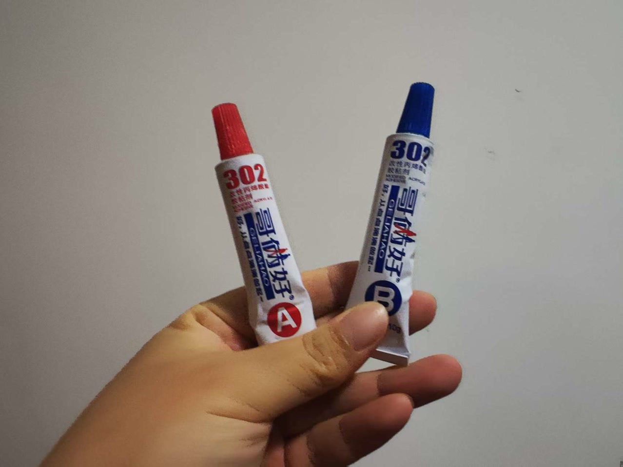
I spent time manually pressing the seams together to squeeze out any trapped air, ensuring a perfectly airtight seal. I carefully aligned the front panel to maintain its designed symmetrical overhang. Since AB epoxy reaches its maximum strength after 24 hours, I left this assembly to cure overnight.
Step 2: Neck Verification & Sound Post
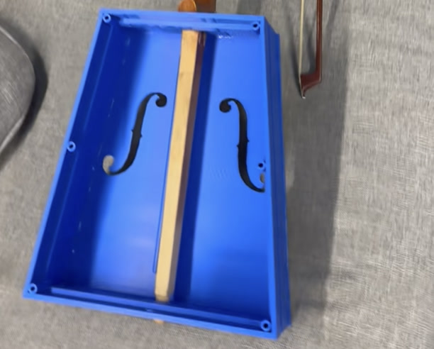
The next day, before doing anything else, I did a dry fit of the wooden neck into the top square slot and bottom round slot of the middle frame. It fit perfectly!
With the neck removed, I installed the 3D-printed sound post using a drop of 401 superglue. The sound post is the acoustic "soul" of the instrument—it structurally bridges the front and back panels, transferring the string vibrations from the front board to the entire body to generate that deep, resonant bass.
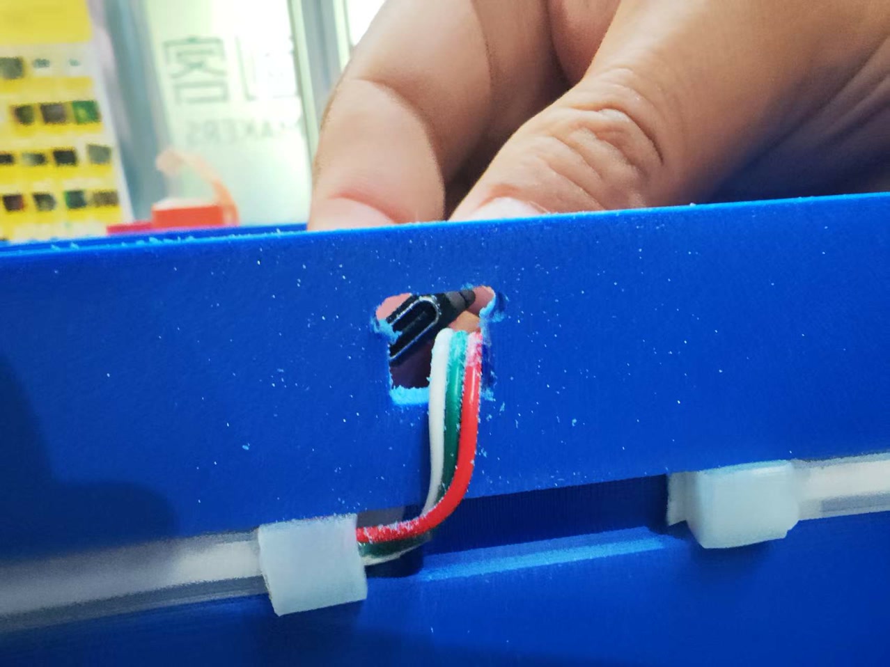
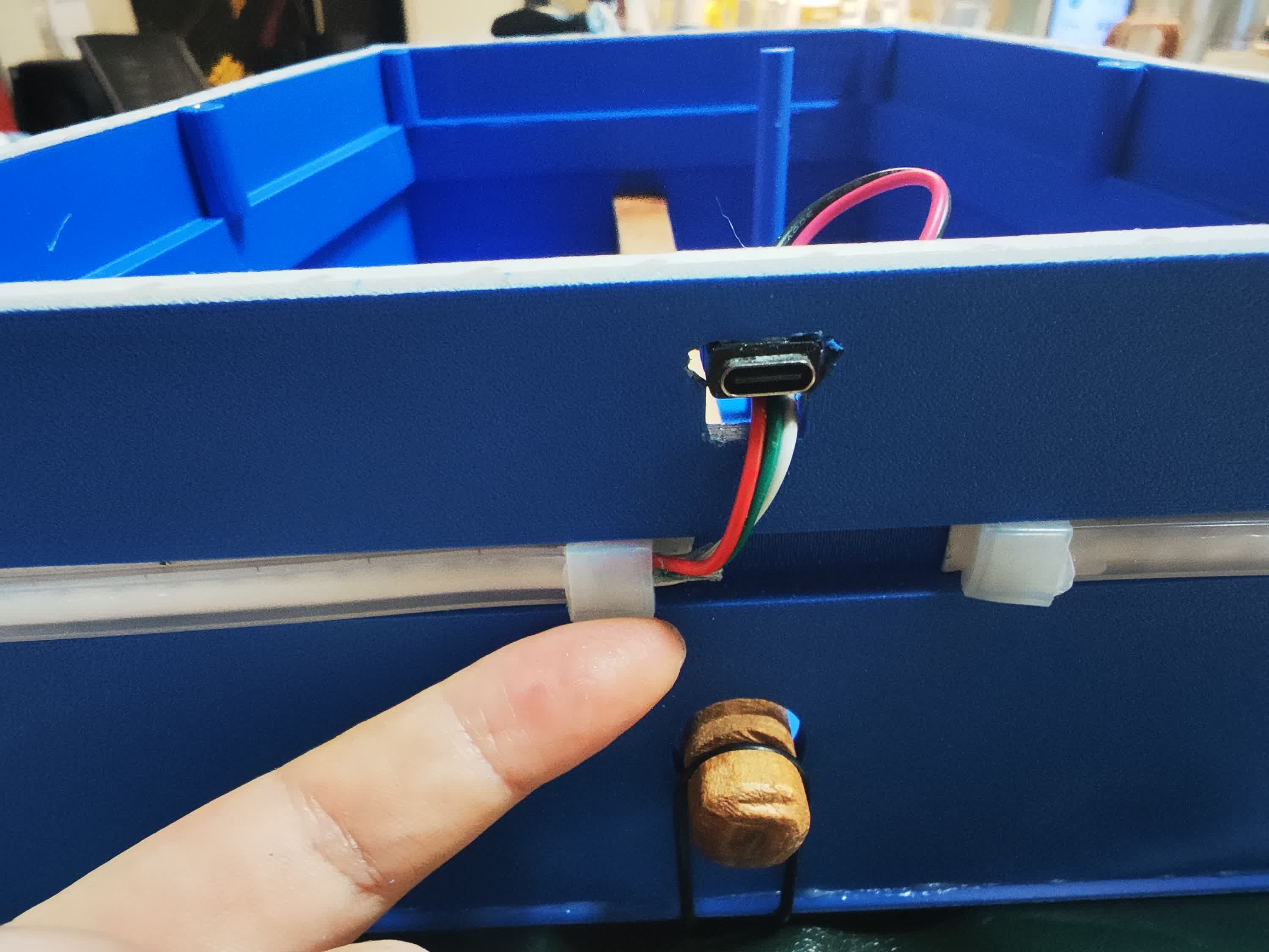
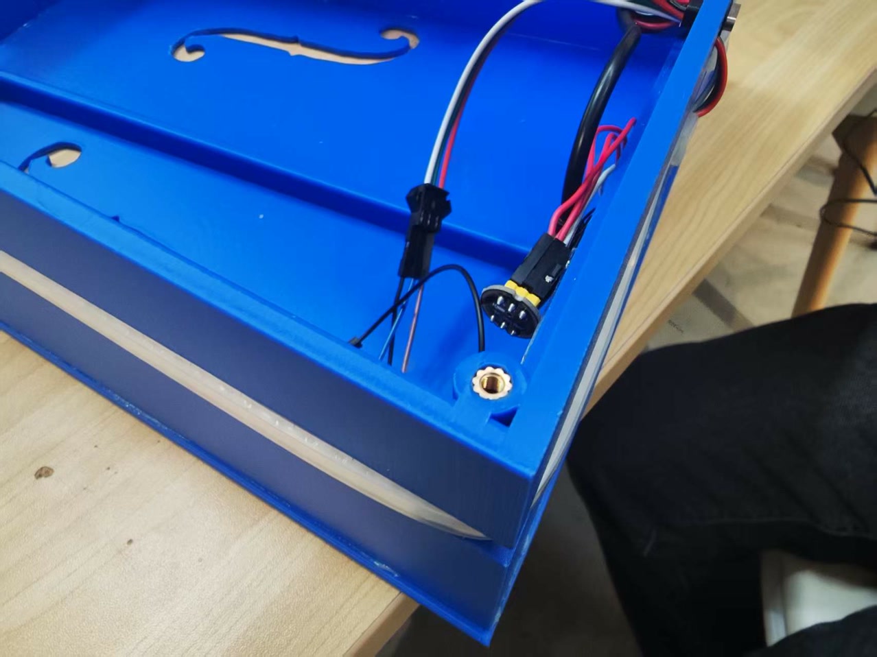
Step 3: Electronics Routing & Troubleshooting
Next, I installed the internal hardware. The 1-meter WS2812 LED strip routed smoothly out of the hole and fit perfectly into the exterior groove. However, I hit a physical bug: my designed 10mm exit hole was too small to pass the battery's Type-C charging port. I had to manually widen the hole with a file, then secure the Type-C port flush with 401 glue.
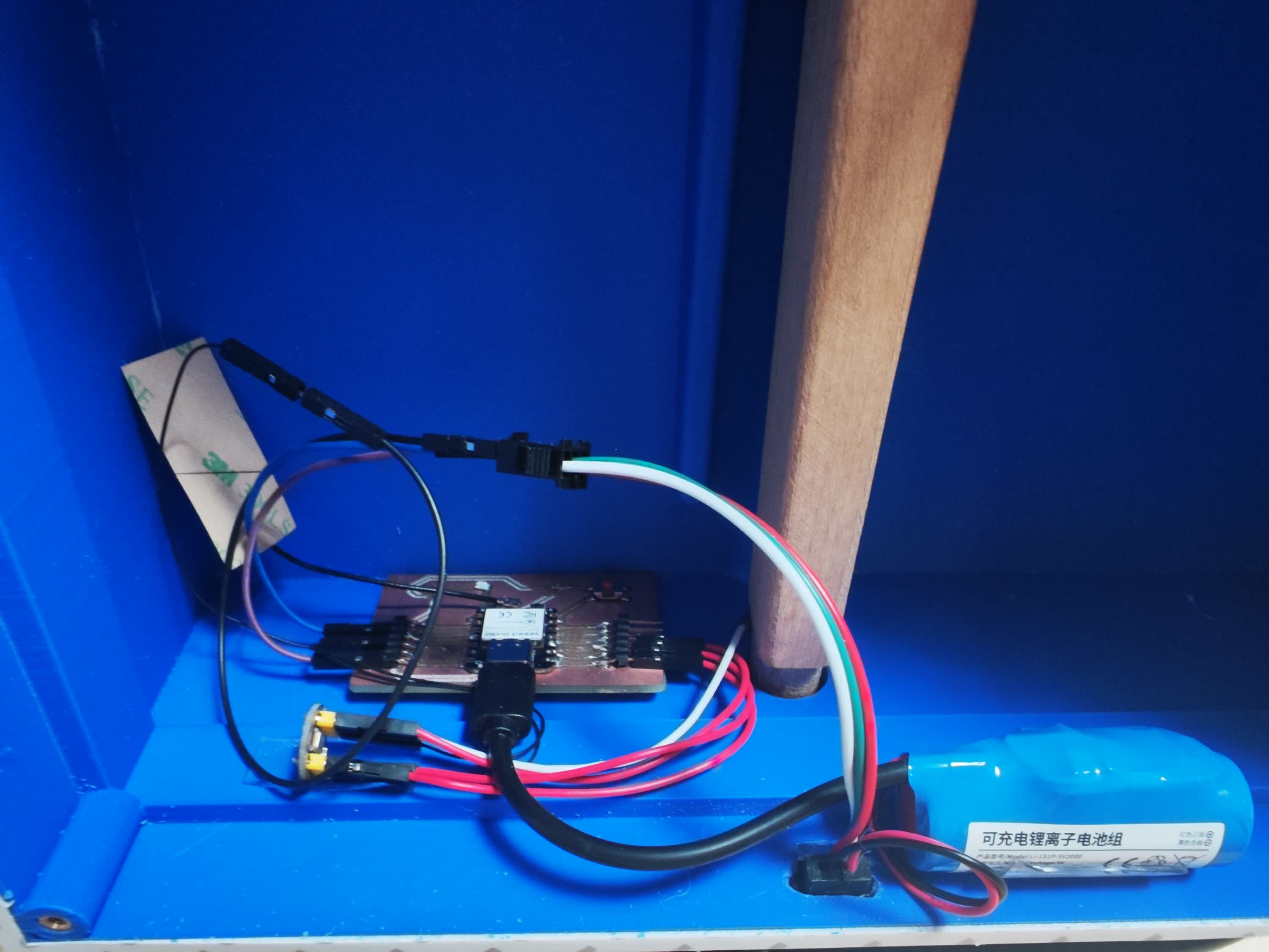
I mounted the PCB and microphone module inside using easily removable nano tape. Crucial acoustic detail: I made absolutely sure no electronic components or wires touched the front panel, as it needs to vibrate completely freely to produce sound.
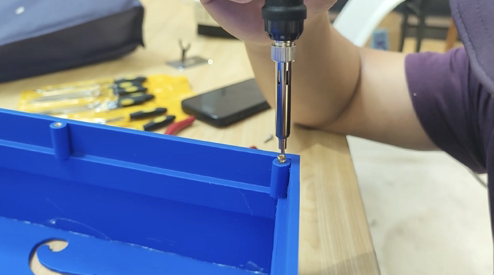
Step 4: The Heat-Set Inserts
This was a tense moment. As a non-engineering student, I researched this method specifically to make the back panel removable yet completely airtight.
Soldering Iron kit, M3 screws, M3 brass heat-set inserts:
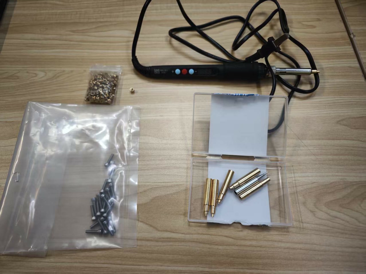
I set my soldering iron to 500°C and carefully pressed six M3 brass heat-set inserts vertically into the 3D-printed screw pillars. It melted in perfectly without damaging the plastic.
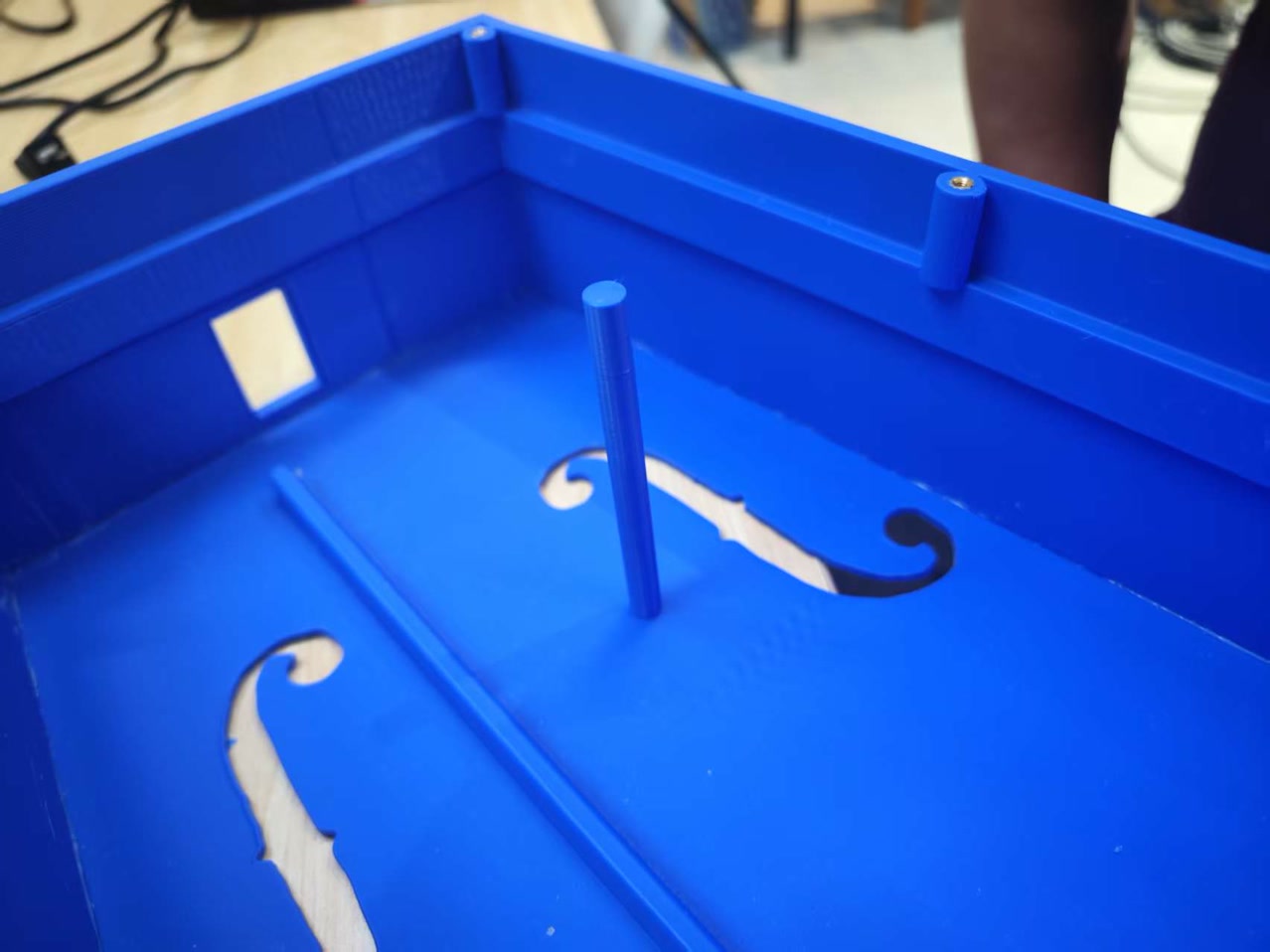
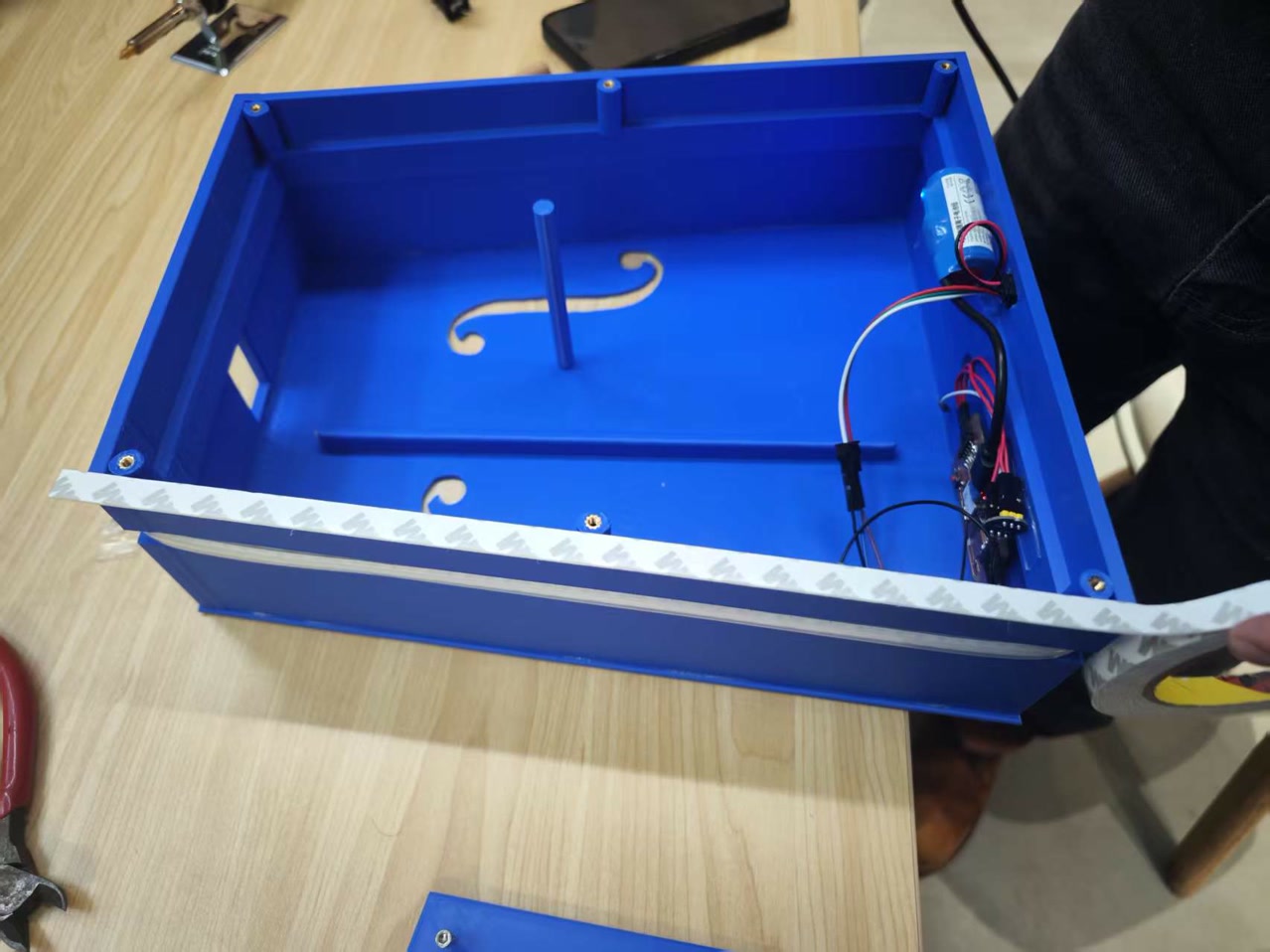
Step 5: Sealing the Acoustic Chamber
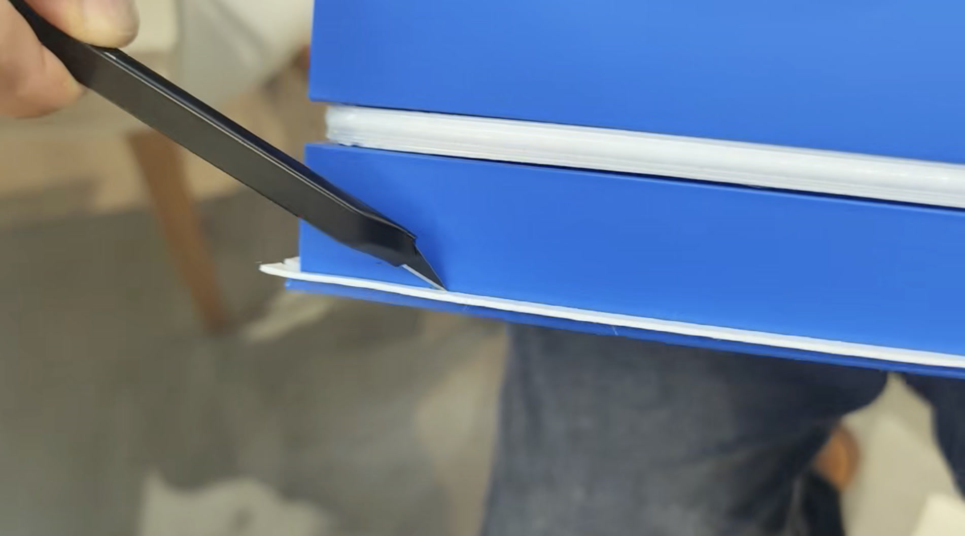
A back panel held by just six screws will leak air, which kills the sound. To solve this, I applied a continuous strip of 1mm thick, 10mm wide 3M acoustic foam tape along the 5mm interior rim of the middle frame.
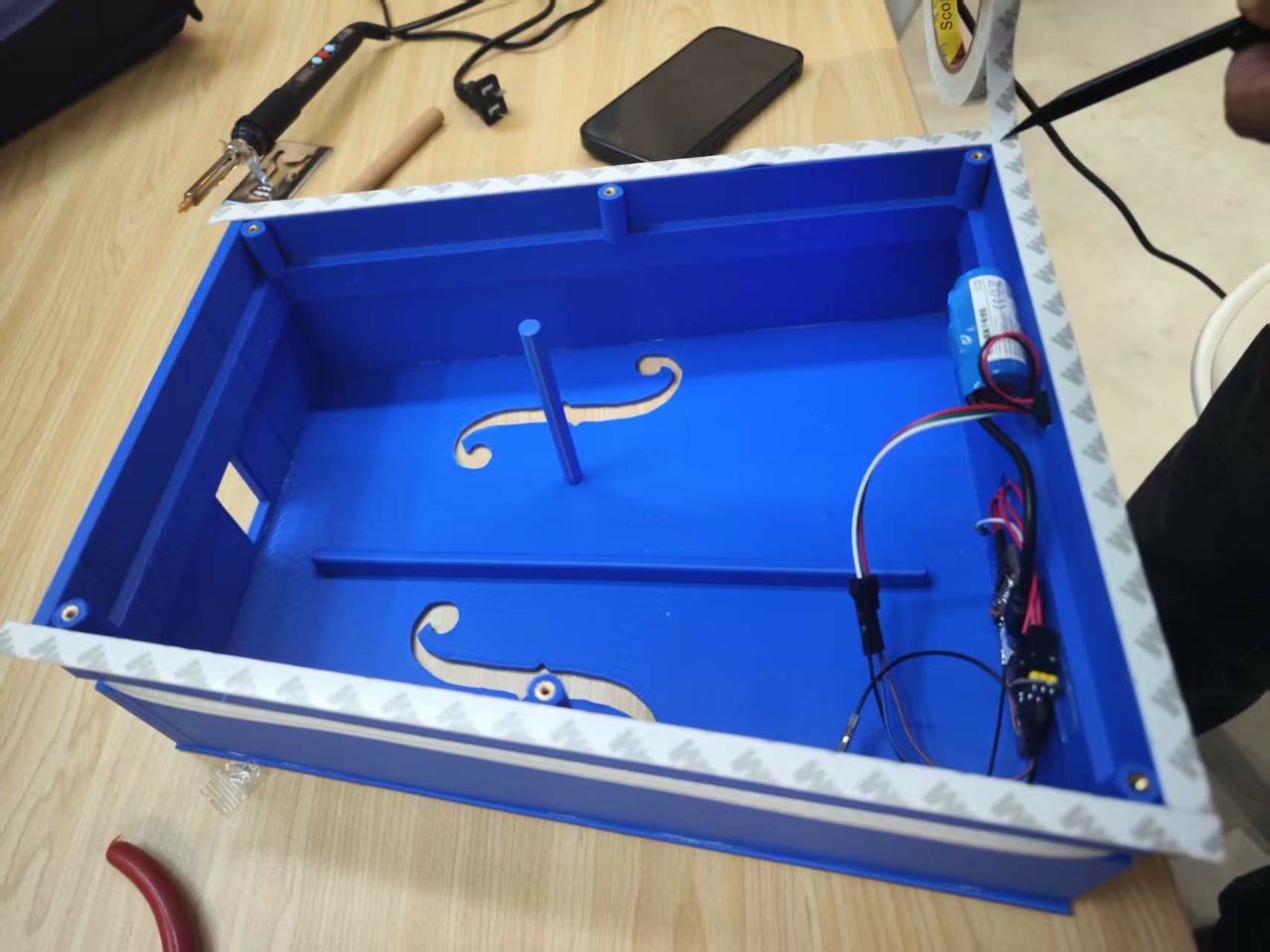
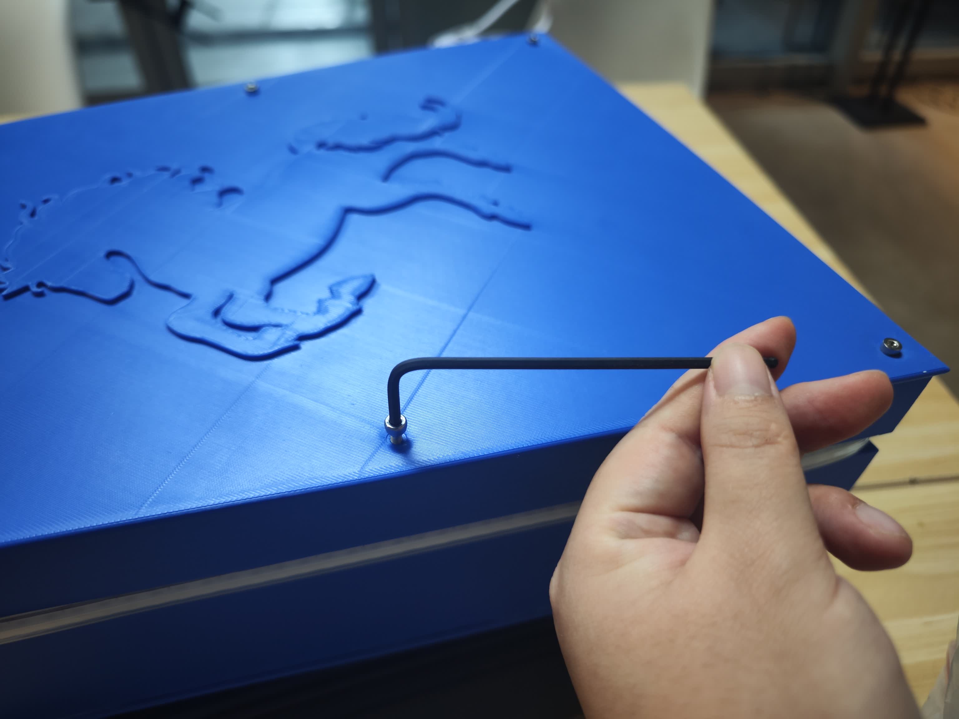
I tightly screwing in the back panel with six M3 screws.
I used a craft knife to carefully trim the excess 5mm of foam sticking out. The chamber was now perfectly sealed.
Then the acoustic box part was entirely integrated.
Step 6: Stringing and The First Note
Since stringing a Morin Khuur requires specific expertise, I invited my Morin Khuur teacher, Mr. Habur, to help me install the strings and tailpiece together.
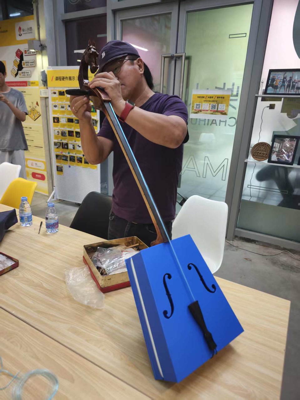
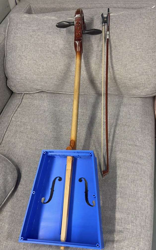
After the integration of wooden neck and strings, this new Morin Khuur was completed.
I tested this piece of Morin Khuur for the first time. The sound was thick, rich, and full of tension. It didn't sound "plastic" at all!
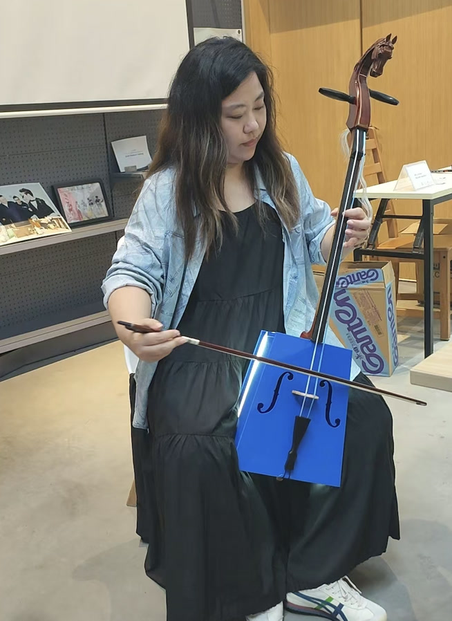
Then came the ultimate test. Mr. Habur played the first note, and we were both thrilled. The LED strip also reacted beautifully to the live playing, though I noted a few minor color and sensitivity glitches that I would later fix by tweaking the code. The 3D-printed acoustic design, the electronic parts, and the whole system integration seemed a success!
Open Source Sharing:
For the Physical Design & Hardware: CC BY-NC-SA 4.0
I am releasing all the 3D STL files, CNC routing parametric files, and PCB gerbers under the Creative Commons Attribution-NonCommercial-ShareAlike 4.0 International License.
-
The Reason: The Morin Khuur is not just a structural object; it carries the beautiful, soulful timbre of Mongolian cultural heritage. My biggest fear is that a large manufacturing factory might take my 3D models and mass-produce cheap, shoddily made plastic replicas to make a quick profit.
-
The Impact: A poorly manufactured version would ruin the acoustic resonance and compromise the visual LED effects. More importantly, it could give the public a completely wrong and disrespectful impression of what a Morin Khuur actually sounds and looks like.
-
The Rule: By using the "NonCommercial" (NC) clause, I ensure that makers, students, and musicians can download, 3D print, and modify the physical design for personal joy and education. However, mass commercial production is strictly prohibited. If others improve upon my physical design, they must share it under the exact same terms (ShareAlike).
For the Software & Firmware: MIT License
The ESP32-C3 firmware, the FFT audio processing code, and the WebSocket Web Dashboard are released under the MIT License.
-
The Reason: My entire journey in Fab Academy—learning to code, parsing data, and building interfaces—relied heavily on the generosity of the open-source community. I want to respect and contribute back to that culture.
-
The Goal: I want more people to experience the pure joy and inspiration that happens when traditional music meets modern technology. By keeping the software fully open and unrestricted, I hope other creators will join in. They can take my FFT visualizer code and apply it to a guitar, a violin, or a completely new interactive art installation. I want the digital soul of this project to be as free and adaptable as possible.
Future Plan:
While the current electro-acoustic prototype successfully meets all initial project goals, the debugging process revealed several areas for optimization. I have planned the following improvements for the next iteration to enhance stability, usability, and integration.
Mechanical and Structural Upgrades
-
A Fully Fabricated Instrument: The current version relies on an upcycled wooden neck, headstock, and bridge. The next step is to design and 3D print these remaining traditional components to achieve a completely digitally fabricated instrument.
-
Improved Enclosure Accessibility: Currently, flashing new firmware requires unscrewing the back panel. I plan to add a customized opening on the middle frame and use a USB-C male-to-female extension cable to expose the XIAO's data port and the battery interface. This will allow for external battery charging and easy reprogramming without opening the resonance box.
Electronics and Hardware Optimization
-
Dedicated PCB Redesign: The current circuit relies on a milled copper board adapted from my Week 6 assignment, which is prone to short circuits and fragile traces. I will design a new, project-specific PCB that properly breaks out the 3.3V pins, uses sturdier connectors, and have it professionally manufactured (e.g., via JLCPCB) to ensure long-term hardware stability.
-
Physical Power Switch: I will integrate a dedicated hardware power switch into the exterior of the resonance box to completely cut off the battery draw when the instrument is not in use.
Software and Interface Enhancements
-
Advanced Visual Algorithms: I plan to write more complex algorithms for the FastLED library to create richer, fluid animations that react to the FFT data, moving beyond the current simple bass/mid/high visualizers.
-
Interactive Web Control: The Web UI will be upgraded from a passive visualizer to an active remote control. Users will be able to send wireless commands to the ESP32 via WebSockets to dynamically switch between different LED animation presets without needing to re-upload code.
What I learned:
Looking back at the entire Fab Academy journey and the development of the new Morin Khuur, my biggest takeaway is the profound difference between making individual components and executing true systems integration.
Specifically, I learned:
-
Acoustics is deeply tied to digital fabrication parameters: I used to think of 3D printing strictly in terms of geometry and visual output. This project taught me to view FDM printing through the lens of material science and physics. Learning how internal damping coefficients (e.g. PETG vs. PLA) and specific slicing choices (100% solid sound posts vs. 20% gyroid soundboards) directly manipulate sound waves was a major breakthrough for me.
-
The absolute necessity of non-blocking code in embedded systems: Before this project, I often relied on simple linear code with delays. Pushing a single-core microcontroller like the XIAO ESP32-C3 to simultaneously process I2S audio, calculate FFTs, drive 160 LEDs, and maintain a WebSocket connection taught me how to write efficient, time-managed, non-blocking C++ code using
millis(). -
Hardware power management is as critical as the code: I learned that electronics design isn't just about routing signals correctly; it's about understanding the physical limits of your power source. Implementing a software-based current limit to prevent hardware failure was a practical lesson in bridging software commands with real-world electrical constraints.
-
The Maker's iterative mindset: Moving from breadboards to a milled PCB, and now planning for a professionally manufactured board in the future, showed me the complete spectrum of prototyping. I learned that a project is never truly "finished," but rather reaches a stable baseline from which the next, more robust version can be developed.
Ultimately, Fab Academy taught me how to think practically like a systems engineer—respecting the laws of physics, working within the constraints of microcontrollers, and seamlessly blending traditional mechanical structures with modern digital networks.
Files:
Morin Khuur - middle frame.stl