Assignment Overview
The objective of this week was to explore the end-to-end workflow of large-format CNC machining. For the Group Assignment, we focused on machine safety, characterizing our specific CNC tool by testing its kerf, runout, and optimal speeds and feeds for the materials provided. For the Individual Assignment, I applied these findings to design and fabricate a parametric, press-fit stool using Onshape, ensuring all joints included proper tolerances and dog-bone reliefs for a successful physical assembly.
Group Assignment
This is the link of our week7 group work:
https://fabacademy.org/2026/labs/chaihuo/docs/week7/week7_group_assignment/
The objective of this group assignment was to characterize our large-format CNC machine. We focused on understanding the machine's safety protocols, determining the actual kerf (material removed), testing runout, and identifying the optimal speeds and feeds for 18mm plywood to ensure high-quality, safe production.
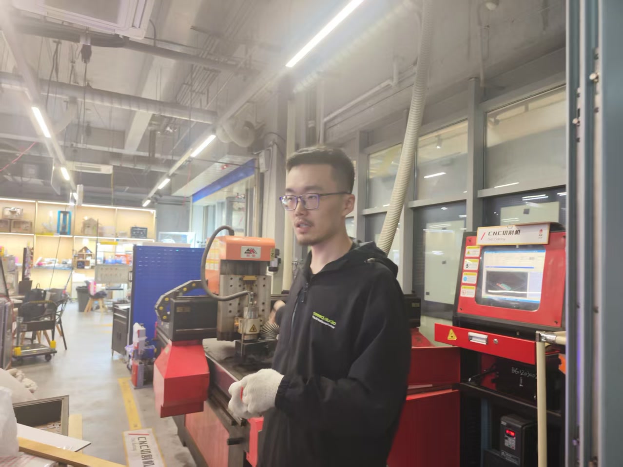
Our instructor Matthew gave us introduction of the machine, and instructions on safety and how to proceed the cutting step by step.
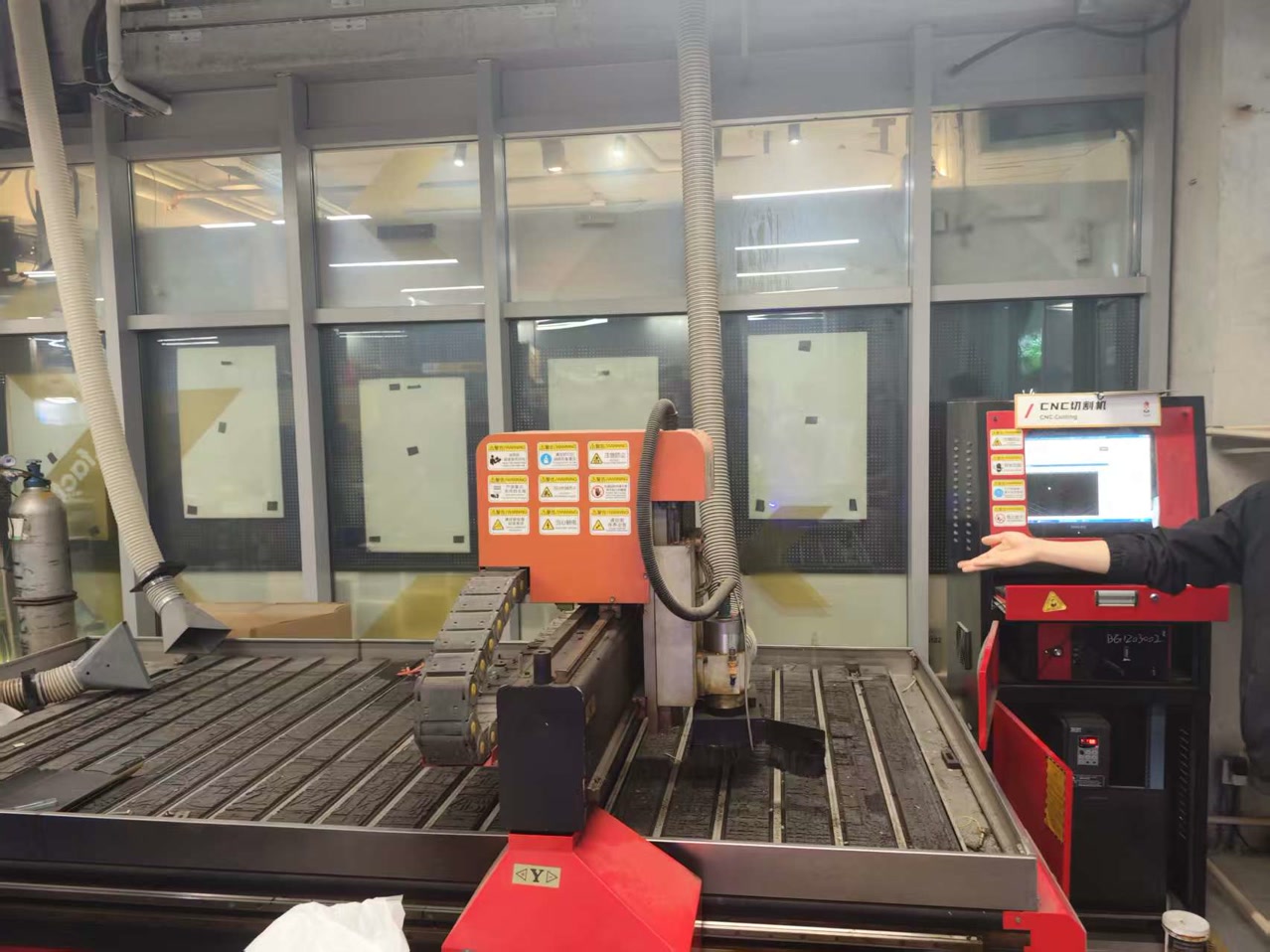
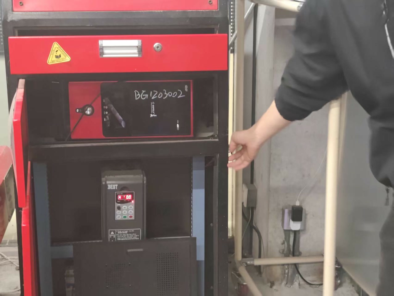
Machine Specifications & Tooling
We used the following equipment for our testing and subsequent fabrication:
- Machine: Tiancheng Xinli 3STX-1325A-style
- Work Area: 1300mm x 2500mm
- Spindle: 3.5kW Air-Cooled Spindle
- Cutting Tool: 8mm Two-Flute Flat End Mill Technical Parameters
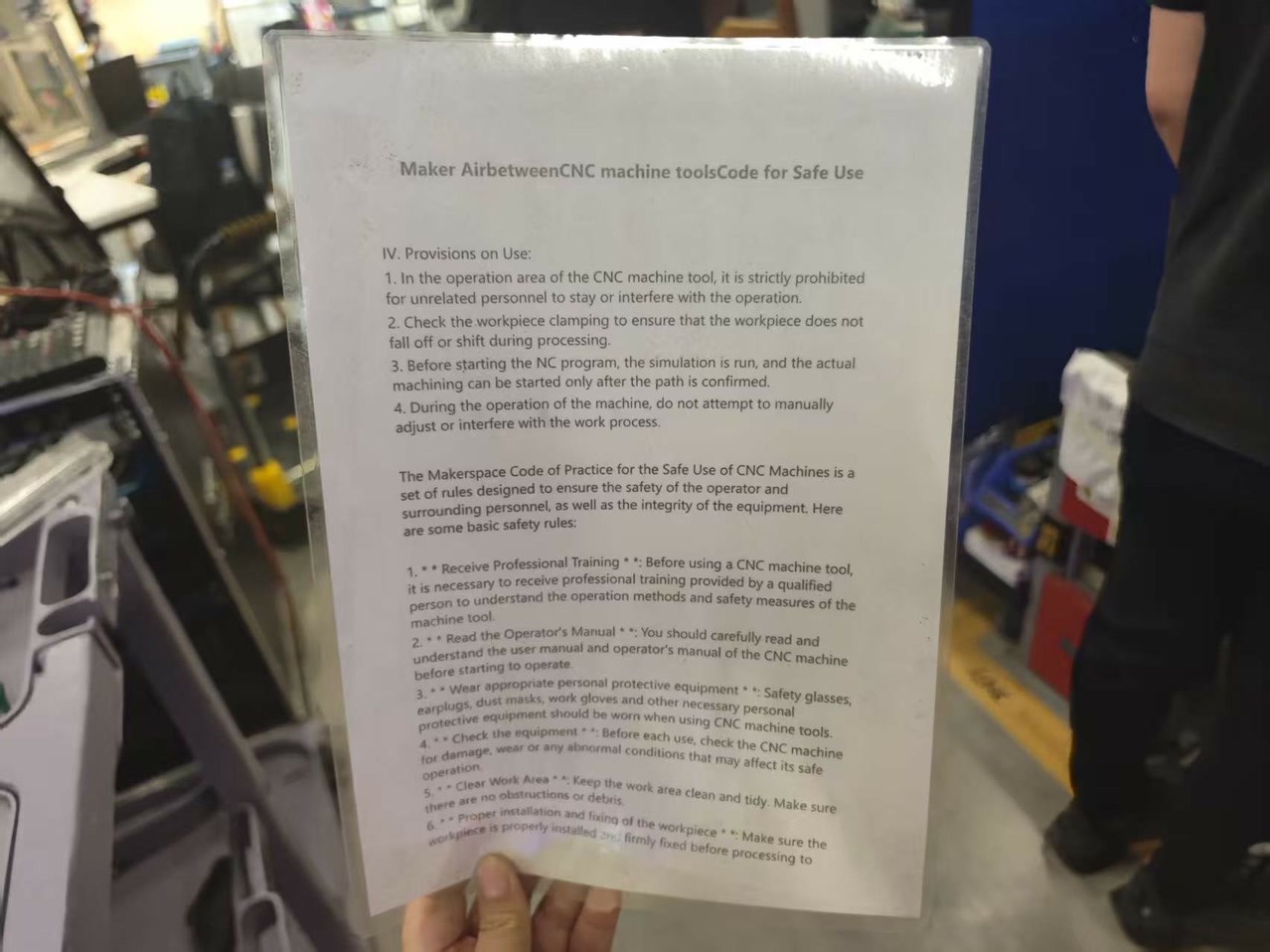
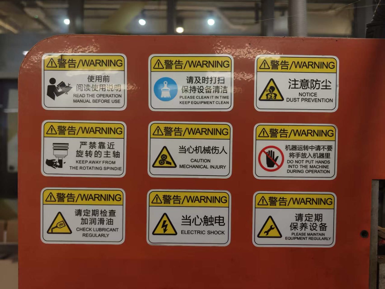
Safety Protocols
Operating an industrial CNC router involves high-speed rotating tools, heavy mechanical movement, and significant noise/dust. We implemented a multi-layered safety strategy to ensure a zero-injury environment.
1. Personal Protective Equipment (PPE)
Before the spindle was even powered on, all team members were required to wear the following:
- Eye Protection: Safety glasses are mandatory to protect against high-velocity wood chips and potential bit breakage.
- Hearing Protection: The 3.5kW spindle and vacuum pump generate noise levels exceeding 90dB; ear muffs or plugs were used at all times.
- Attire: We strictly prohibited loose clothing, dangling jewelry, and untied long hair, which could be caught in the rotating spindle or rack-and-pinion drive.
2. Machine Pre-Start Checklist
To prevent mechanical failure or accidents, we conducted a visual inspection:
- Collet & Nut Inspection: Ensuring the 8mm collet was clean and the nut was tightened securely with the appropriate wrenches.
- Work Area Clearance: Checking that the gantry's path was free of tools, screws, or debris.
- Sacrificial Board (Spoiler Board): Confirming the board was surfaced and level to prevent uneven cutting forces.
- Emergency Stop (E-Stop): Locating and testing the physical E-Stop buttons on both the handheld DSP controller and the machine chassis.
3. Operational Safety Rules
- The "Two-Person" Rule: One person operates the controller while a second person stands at a safe distance to act as a "spotter," ready to hit the E-Stop if anything goes wrong.
- Distance: No one is allowed within the "Yellow Tape" zone (the machine's footprint) while the spindle is moving.
- Vacuum & Dust Collection: The dust extractor must be turned on to prevent the buildup of flammable sawdust and to maintain visibility of the cutting path.
- Fire Prevention: Wood friction can lead to charring or fire if the feed rate is too slow. We kept a fire extinguisher within 3 meters of the machine and monitored for smoke.
4. Post-Process Safety
- Spindle Full Stop: We never reached into the machine area until the spindle had come to a complete 100% stop.
- Bit Removal: CNC bits remain extremely hot after cutting 18mm plywood; we allowed the tool to cool down or used heat-resistant gloves for removal.
- Cleanup: Using a vacuum (not compressed air) to clean the machine to avoid blowing fine dust into the air or into the linear rails.
Board Material
For the characterization process, we selected high-density fiberboard (HDF) as the test material.
- Nominal thickness: 18 mm
- Measured thickness: 18.3 mm
- Board dimensions: 1220 mm × 2440 mm
- Material property: high-density, heavy, and compact Before starting the machining process, we measured the actual thickness of the board using calipers, since nominal specifications may differ from the real material. The measured value is critical for accurate joint design and proper fitting.
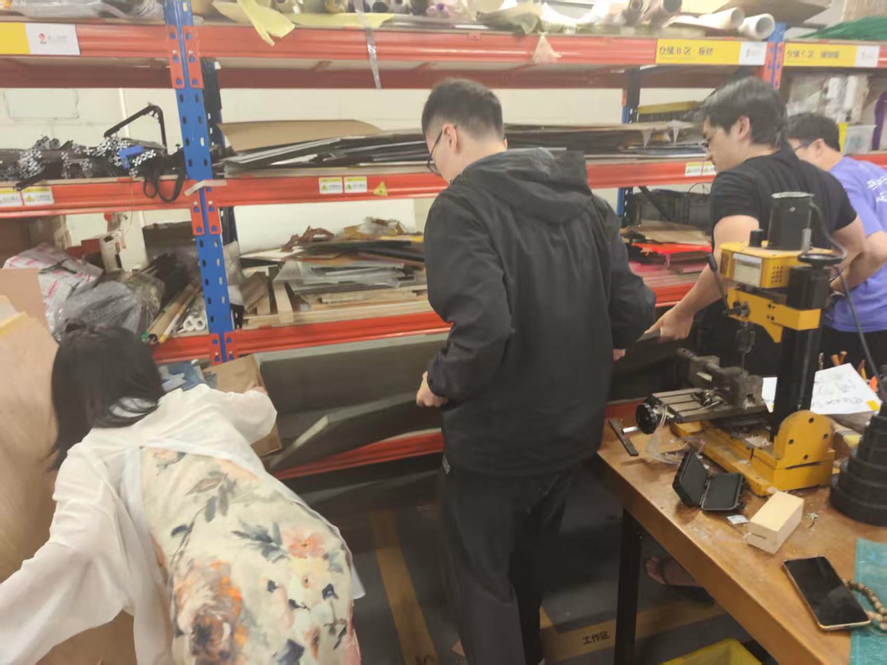
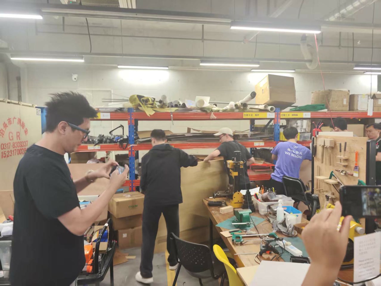
The board is heavy, several fellows worked together to carry the board from the storage place to the CNC machine.
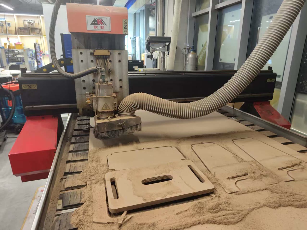
Get prepared for Cutting
Before placing the board, we thoroughly cleaned the machine bed. Even small chips or dust particles can cause the material to sit unevenly, which may lead to inconsistent cutting depth during the machining process.
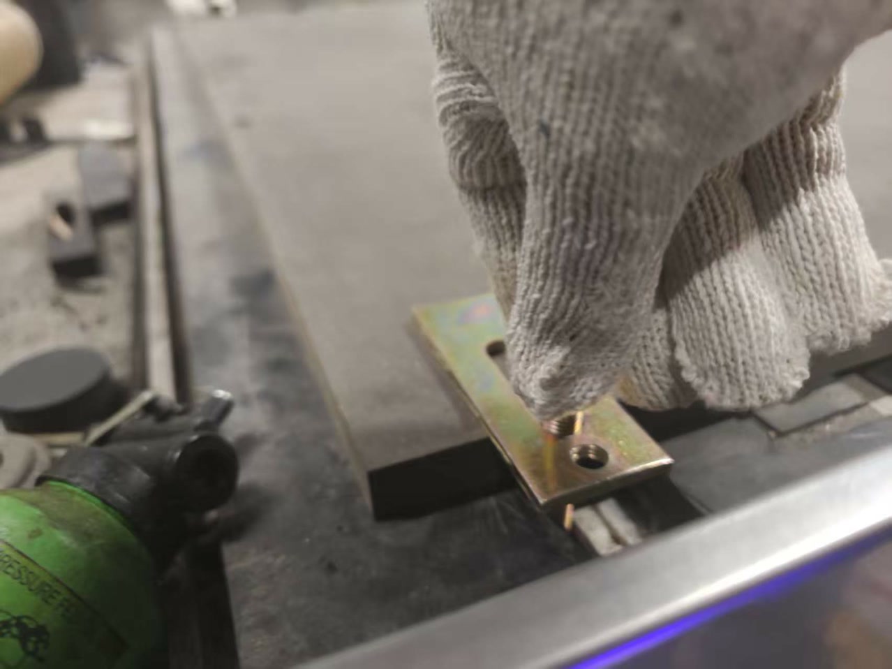
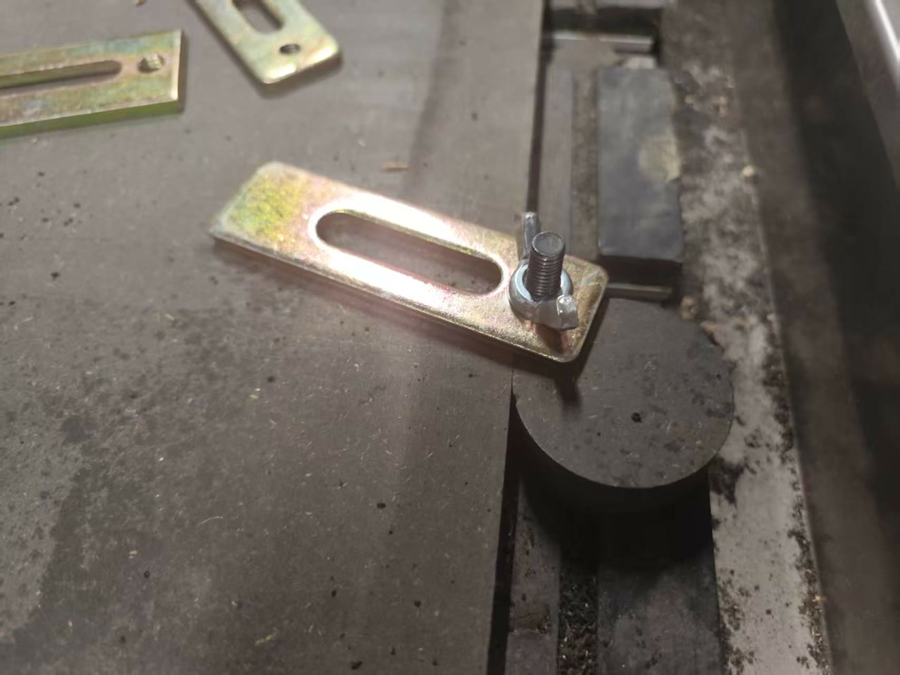
Securing the Board
The board was placed flat on the machine bed and firmly fixed along the edges using screws into the sacrificial layer. Special attention was given to ensure that the fasteners were positioned outside the toolpath area to prevent interference with the cutting operation.
Before starting the machining process, we defined the machine’s work origin. The spindle was jogged manually to the corner on the left side of the board, where the X and Y zero positions were established.
For the Z axis, we used the touch-off probe (or alternatively lowered the end mill carefully by hand until it just contacted the material surface) and then set the Z zero at that point.
An important detail to consider is that the Z reference must be set relative to the top surface of the material, rather than the machine bed. If the board is slightly uneven or the table is not perfectly leveled, setting Z from the bed can result in inconsistent cutting depths, even when the toolpath appears uniform in the design file.
Settings on MasterCAMFirst of all, we used ChatGPT to assist in converting our DXF test files into G-code files that could be executed by the CNC machine. This helped streamline the workflow from design to machining.
Toolpath SettingsFor contour cutting, which is the most commonly used operation during the characterization process, we focused on configuring several essential parameters to ensure accurate and consistent results.
Toolpath type: 2D contour
Tool diameter: 8 mm
Spindle speed: 15,000 rpm
Cutting feed rate: 5000 mm/min
Plunge rate: 1000 mm/min
Depth per pass: 8 mm
Total cut depth: Full board thickness + 0.2 mm into spoilboard
Compensation direction: Right to left
Testing Process
To understand the performance of our CNC machine, we designed a comprehensive test file that included:
-
Pocket and Contour Cuts: To observe the surface finish at various feed rates.
-
Kerf Measurement: A slot of a known width to calculate exactly how much material the 8mm bit removes.
-
Press-fit Graduated Slots: A series of slots with slightly different widths to determine the ideal tolerance for a "glue-free" assembly. We conducted the tests with the spindle speed fixed at 18,000 RPM while varying the feed rate.
-
Feed Rate Impact: We noticed that at higher feed rates, the exit edges of the plywood became noticeably rougher. Conversely, at very low feed rates, there was slight discoloration on the wood, indicating heat buildup due to friction.
-
Depth of Pass: We compared shallow passes versus aggressive deep cuts. While cutting in multiple passes (6mm each) took longer, it resulted in much more consistent and vertical walls compared to a single full-depth pass, which put significant load on the tool.
-
The Inside Corner Issue: A key takeaway was observing how the rounded bit leaves a radius at inside 90° corners. We confirmed that for a square-edged part to seat fully, we must implement dog-bone reliefs in our designs. Based on our test results, we established the following "sweet spot" settings for the 18mm plywood using our 8mm flat end mill:
-
Material: HDF / MDF, approximately 18.3 mm thickness
-
Bit diameter: 8 mm flat end mill
-
Spindle speed: 24,000 rpm
-
Feed rate: 2000 mm/min
-
Plunge rate: 1000 mm/min
-
Depth per pass: 6 mm
-
Tabs: 3 mm height, 5 mm width, placed at corners
-
Press-fit slot offset: −0.4 mm per side relative to measured board thickness
-
Kerf (average): Approximately 0.4 mm
Lessons Learned
This characterization process replaced guesswork with data. My key takeaways for the individual project are:
- Measure First: Never trust the "nominal" 18mm label. Our board was actually 18.3mm. Designing based on caliper measurements is the only way to ensure parts fit.
- Account for Kerf: The machine removes slightly more material than the bit's physical diameter. This must be compensated for in the joint design.
- Corner Logic: Always plan for the bit's radius. Whether using dog-bones or extending slots, internal corners require active design intervention.
- Stability: Properly securing the board and following a logical cut order (Inside cuts before Outside cuts) is essential for both safety and precision.
Individual Assignment
Overview
The goal of this assignment is to design and fabricate a parametric interlocking stool using CNC (Computer Numerical Control) machining. The project follows a "Design for Manufacturing" (DfM) workflow, where a digital model is translated into a physical, functional object. The stool is designed to be press-fit, meaning it relies on precise geometry and friction for assembly, requiring no screws, glue, or external fasteners.
Learning Objectives & Focus
- Parametric Engineering: Mastering the use of variables (such as #thickness and #gap) in Onshape. This ensures the design remains flexible and can be instantly adjusted to accommodate different material thicknesses or machine tolerances.
- Joinery Logic & Clearance: Learning to design interlocking slots and "dog-bone" fillets. Since CNC router bits are round, dog-bone reliefs are essential at internal corners to allow rectangular parts to seat fully and flush.
- 3D to 2D Workflow: Navigating the transition from a 3D assembly to a 1:1 scale production-ready DXF file, including proper part nesting and orientation for efficient material use.
- CNC Fabrication Logic: Understanding the end-to-end machining process, from setting toolpaths (profiles and tabs) in CAM software to actual physical cutting and post-processing.
OnShape Design of the Stool
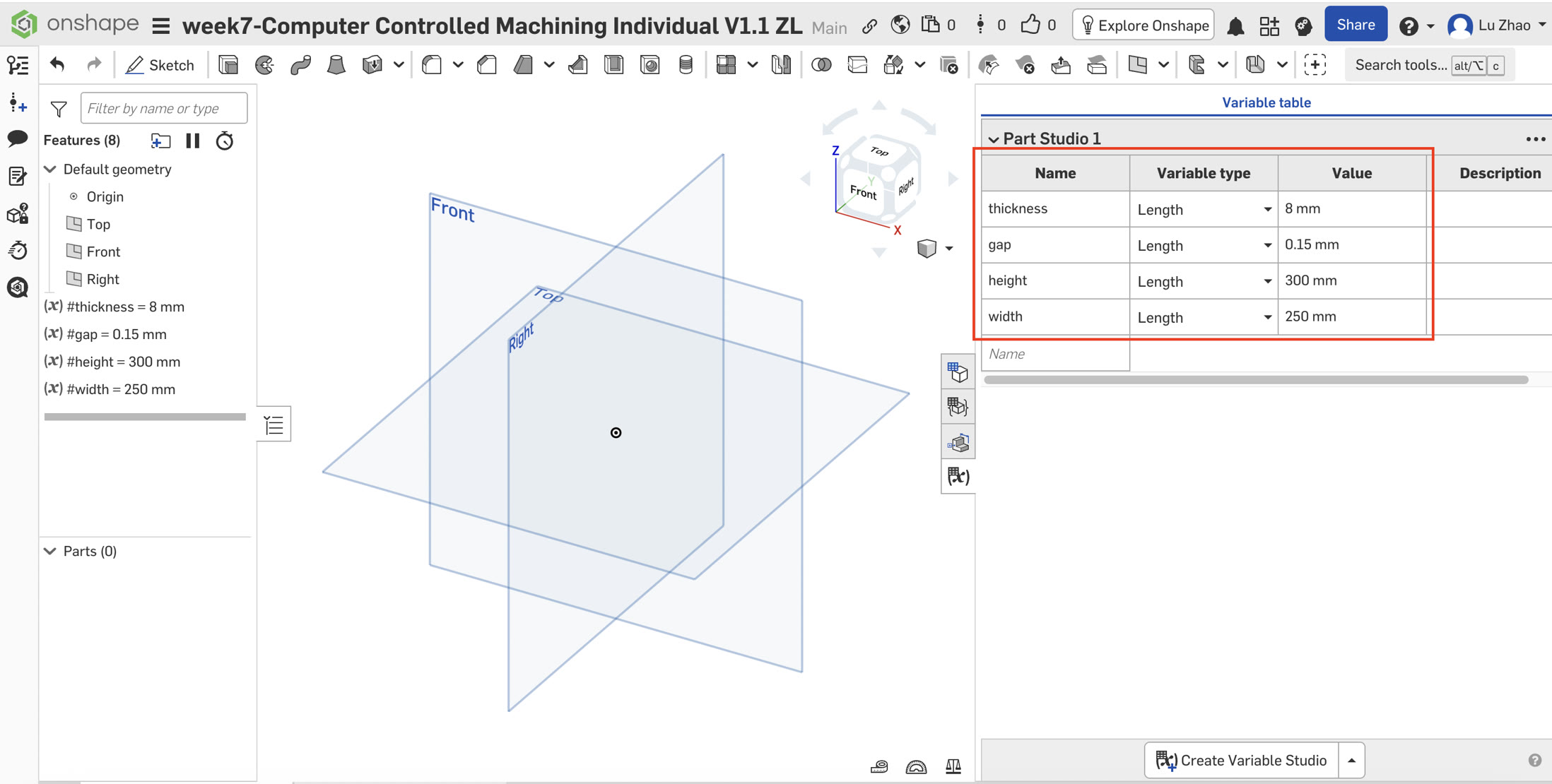
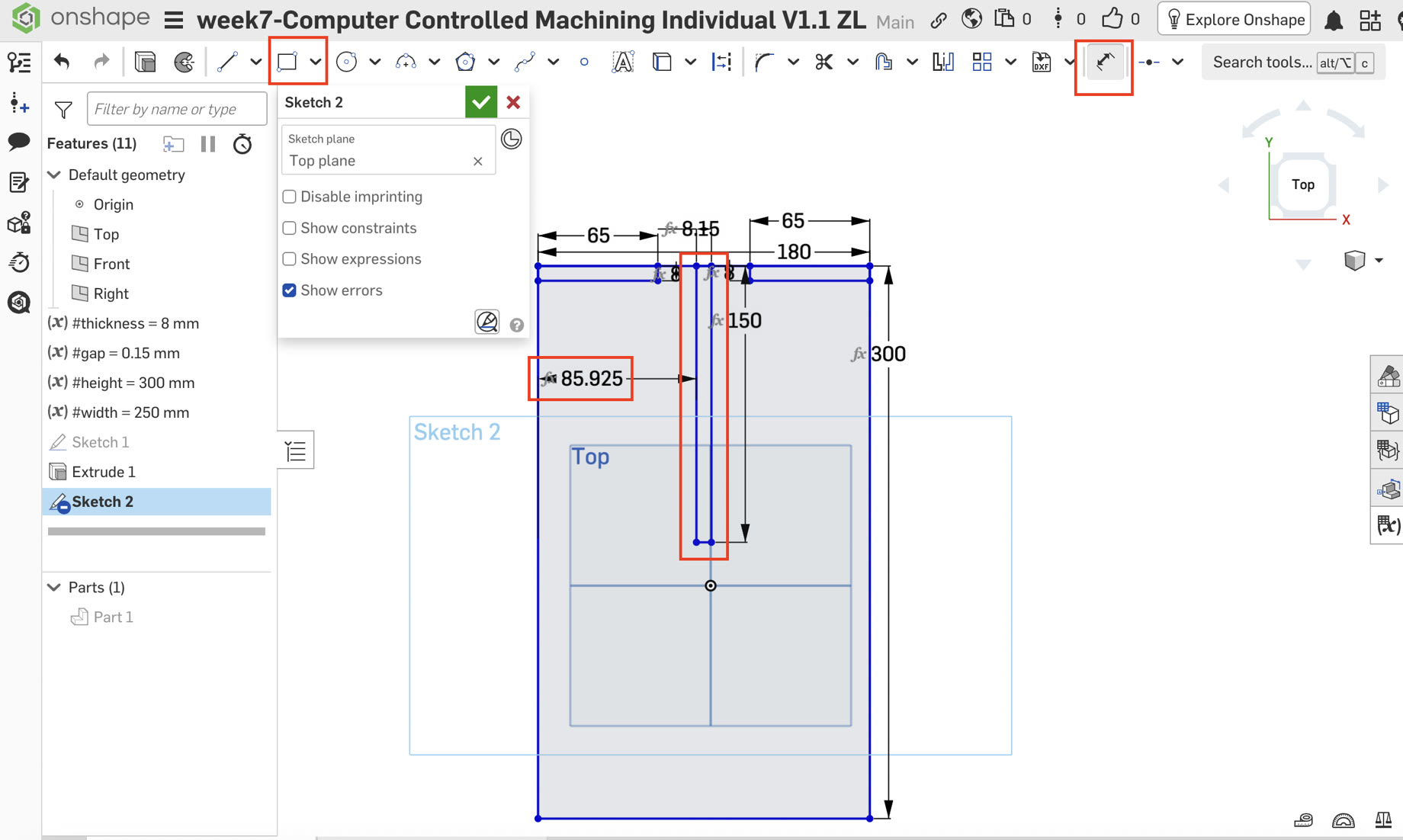
1. Initial Setup and Parametric Variables
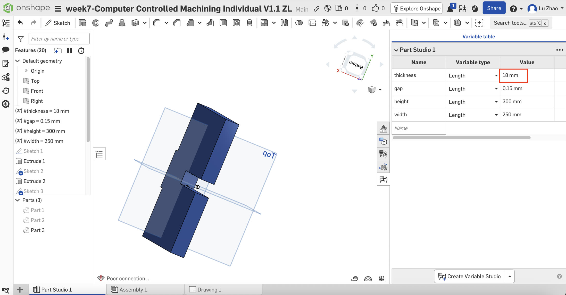
The design began with establishing a Variable Table to ensure the model adapts automatically to material changes.
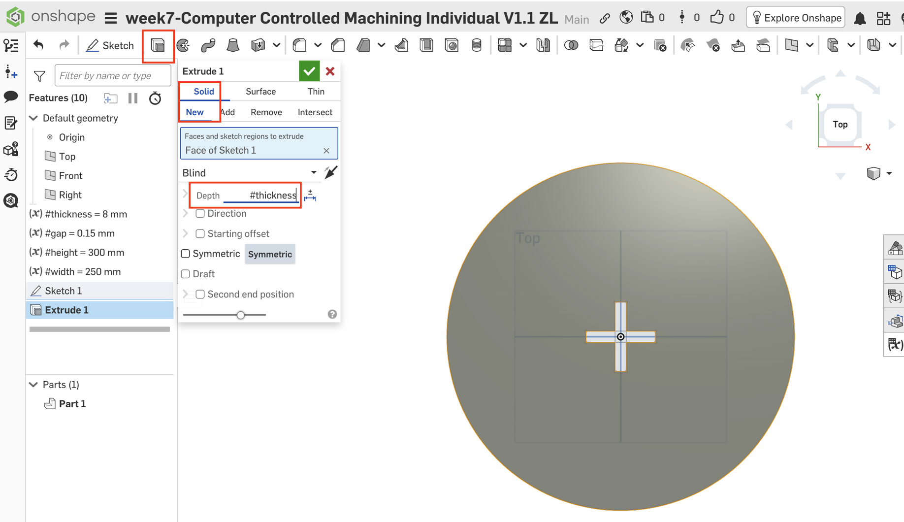
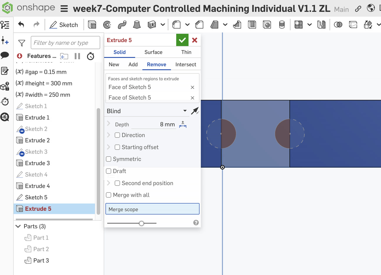
- #thickness: 8mm (The measured thickness of the plywood).
- #gap: 0.15mm (Tolerance for the kerf and fit).
- #height: 300mm (Overall height of the stool).
- #width: 250mm (Diameter of the seat). In my Onshape model, I defined a #gap variable of 0.15mm to ensure a press-fit connection. Unlike the kerf compensation I handled in the laser cutting week, for this CNC project, the tool diameter compensation is handled by the CAM software, allowing me to focus on the mechanical fit (gap) in the design stage.
Understanding the distinction between Gap and Kerf is essential for precision in digital fabrication. In laser cutting, Kerf refers to the width of the material actually removed by the laser beam. To ensure a tight fit, the designer must offset lines outward to compensate for this "burnt-away" material.
In contrast, the Gap (or tolerance) used in this CNC project is an intentional design offset. Because a CNC bit is a physical rotating tool and wood fibers can be irregular or slightly swollen, adding a #gap such as 0.15mm to the slot width is crucial. Unlike the passive compensation of kerf, this gap is a proactive adjustment that allows components to slide together smoothly without excessive force, achieving a stable "press-fit" while accounting for material friction. By using a parametric variable for the gap, I can fine-tune the tightness of all joints globally without needing to redraw the entire model.
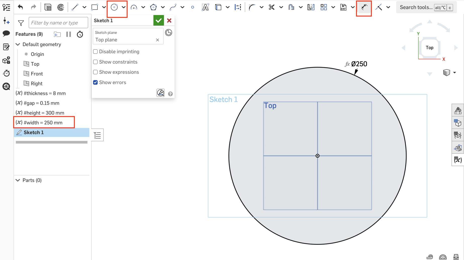
2. Component A: The Seat (Top Plate)
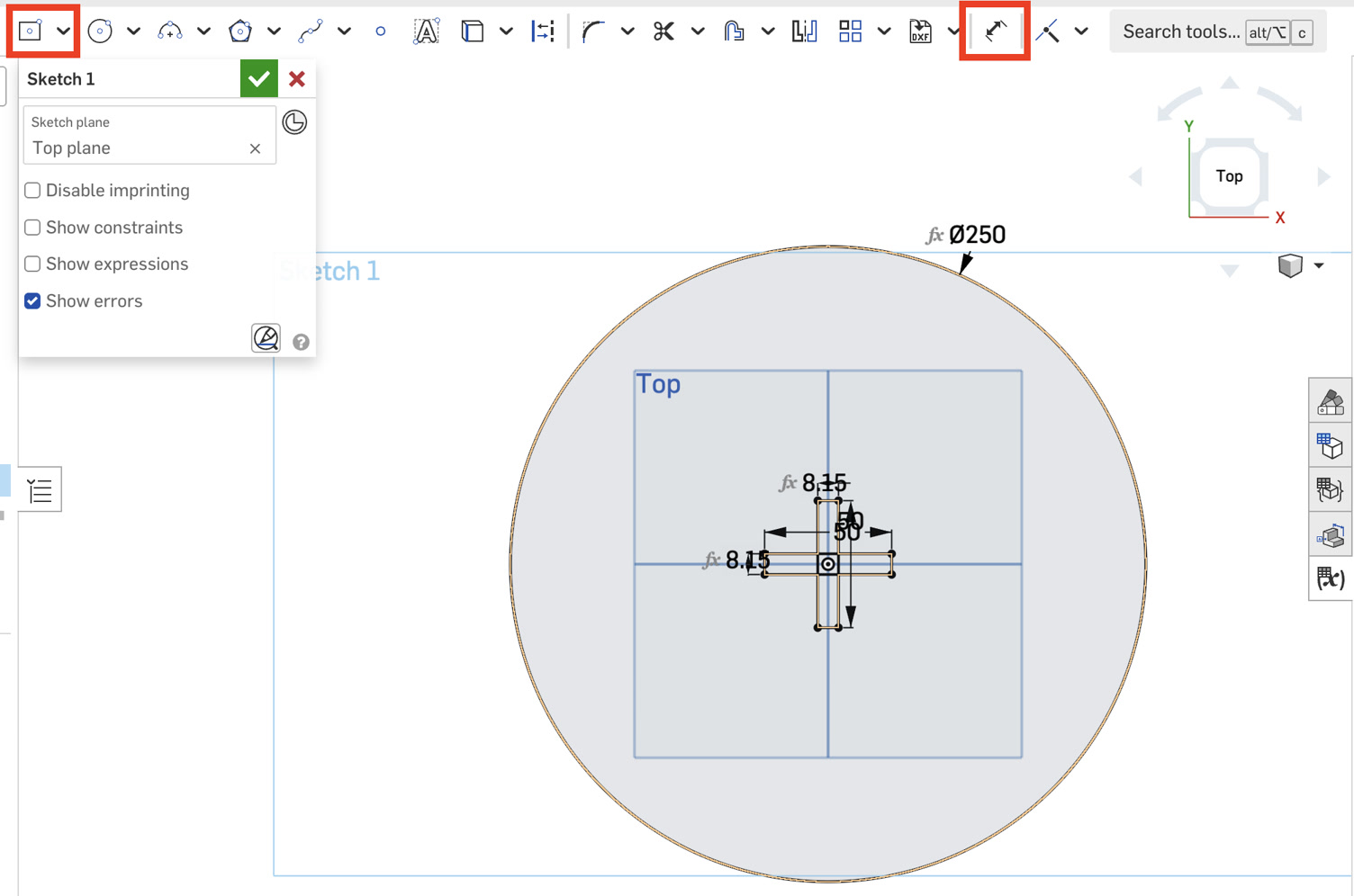
Sketching: Created a new sketch on the Top Plane. Drew a center-point circle with a diameter of #width.
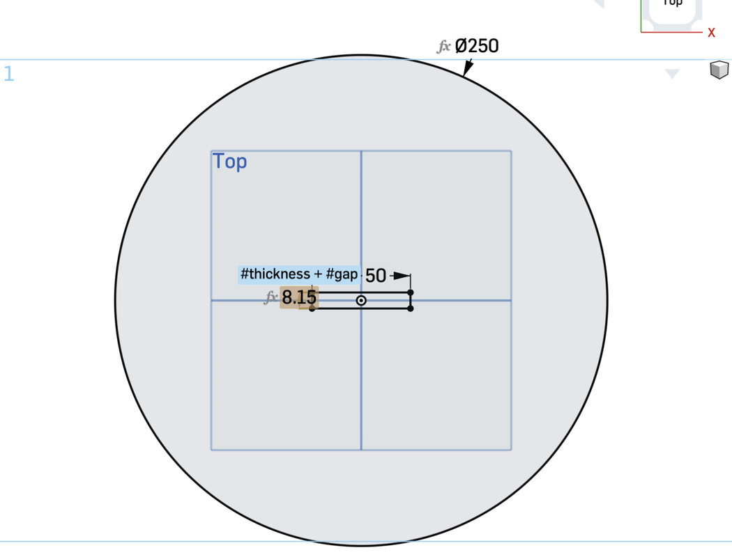
Cross-Slot: Used the Center Point Rectangle tool to draw two perpendicular rectangles at the origin.
Horizontal: 50mm width by (#thickness + #gap) height.
Vertical: (#thickness + #gap) width by 50mm height.
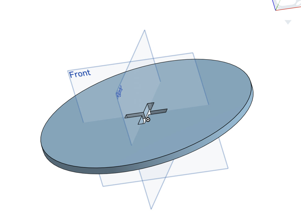
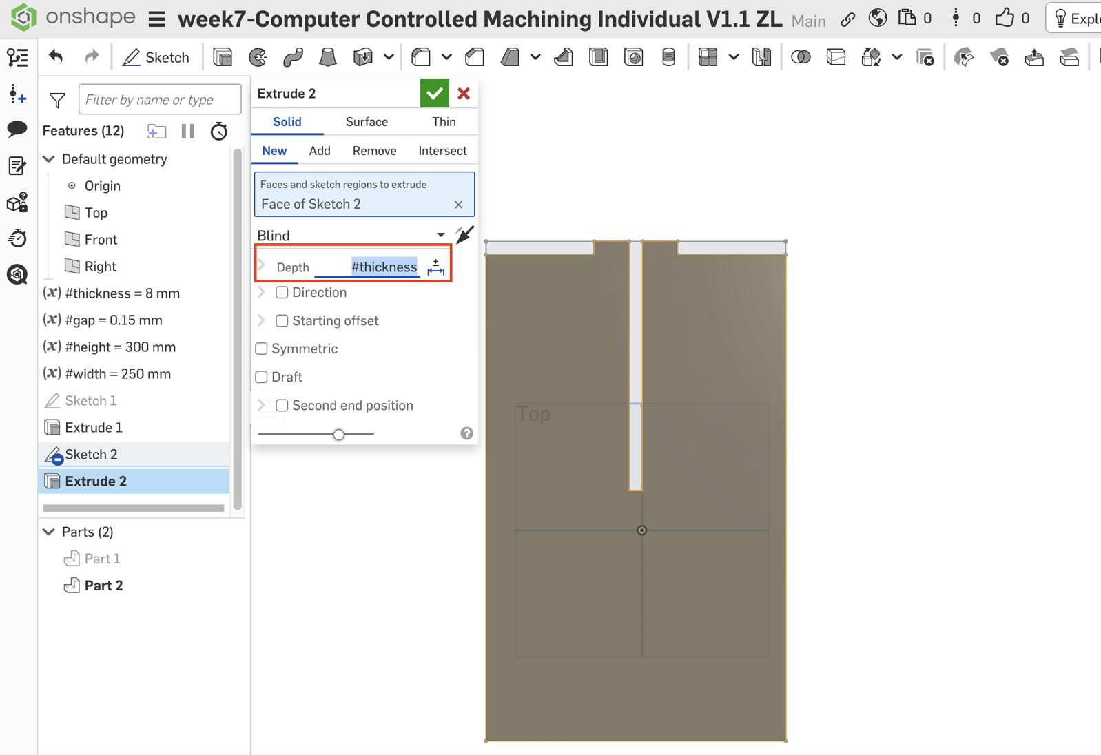
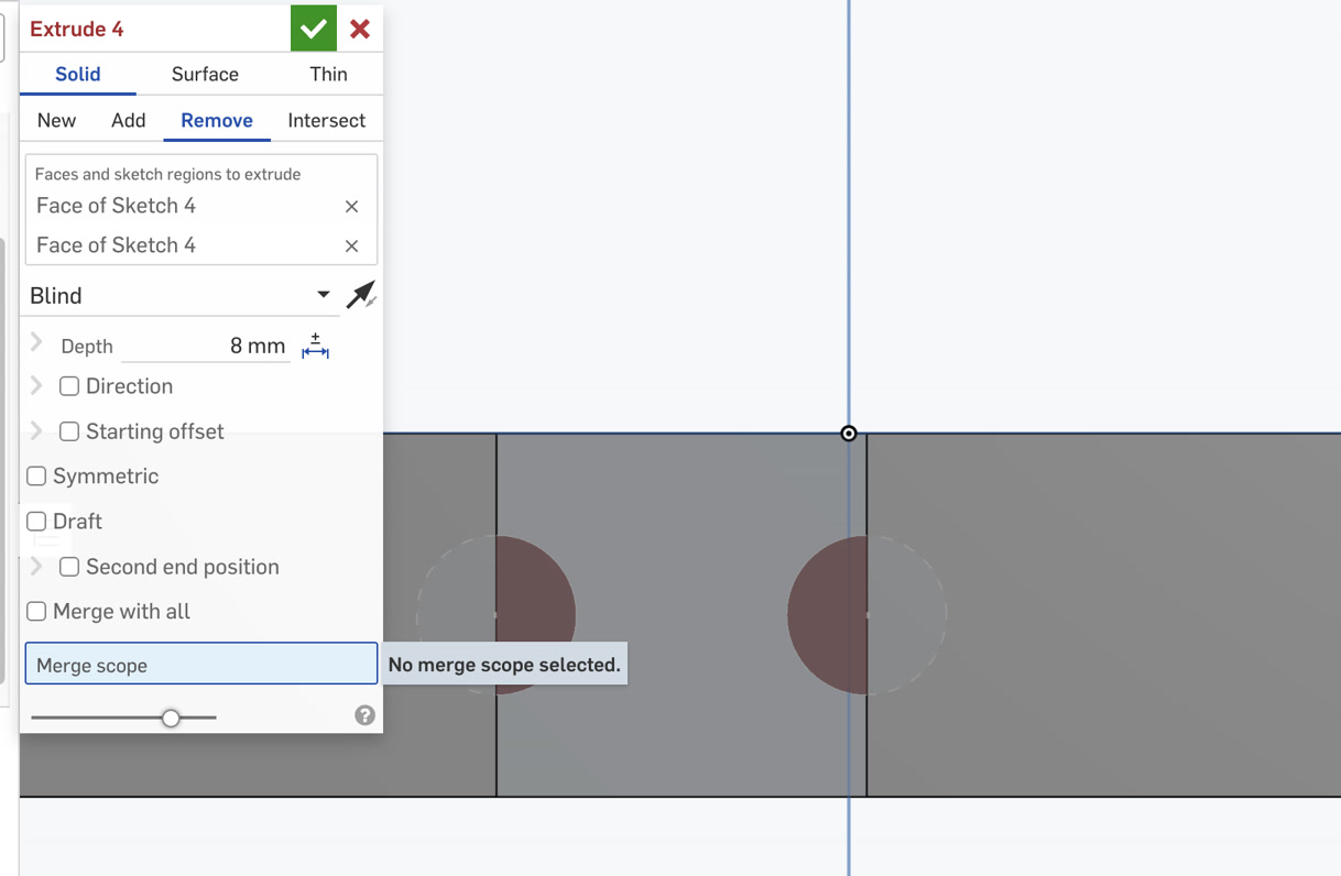
Extrusion: Performed a Solid New Extrude on the circular region (excluding the cross and dog-bones) with a depth of #thickness.
3. Component B: Leg A (Upper Slot)
Sketching: Selected the Front Plane to ensure the leg stands vertically.
Main Body: Drew a corner rectangle (180mm wide x #height tall).
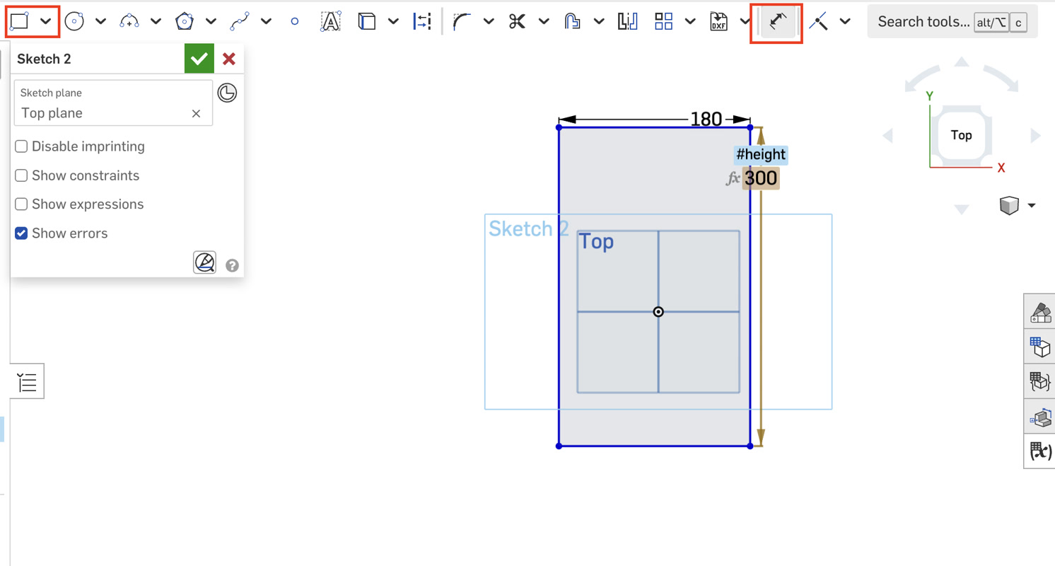
Tenon & Shoulders: Sketched two 65mm x #thickness rectangles at the top corners. These are removed later to create the 50mm central tenon that fits into the seat.
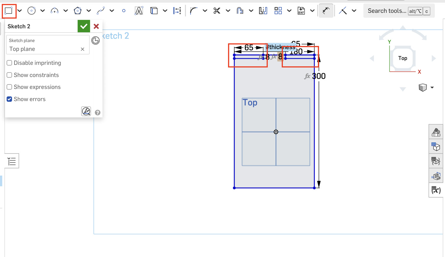
Upper Connection Slot: A central slot was drawn from the top edge downwards.
Dimensions: Width = (#thickness + #gap), Depth = #height / 2 (150mm).
Constraint: Applied a dimension formula to center the slot: (180mm - (#thickness + #gap)) / 2.
Extrusion: Used Extrude New for the main body and set the depth of #thickness.
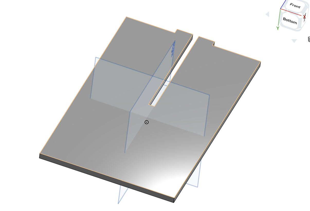
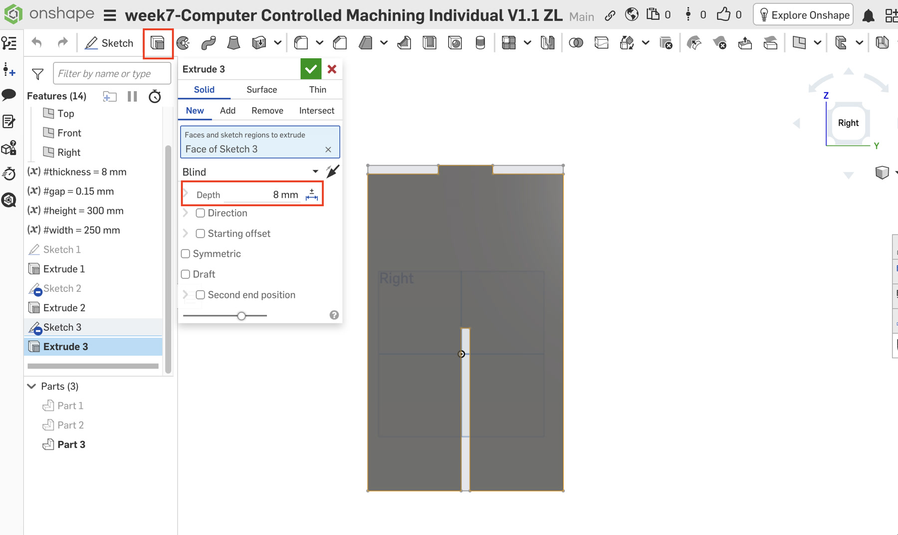
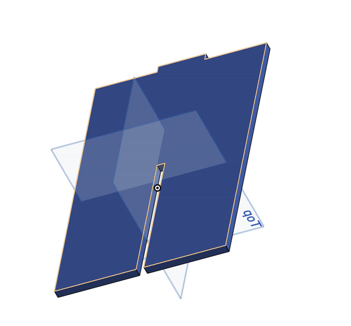
4. Component C: Leg B (Lower Slot)
The structure of Leg B is almost same as Leg A, but the connection slot position is opposite.
Sketching: Selected the Right Plane to create a perpendicular orientation to Leg A.
Geometry: Repeated the main body and shoulder steps from Leg A.
Lower Connection Slot: Unlike Leg A, this slot was drawn from the bottom edge upwards.
Dimensions: Width = (#thickness + #gap), Depth = #height / 2.
Constraint: Used the same centering formula: (180mm - (#thickness + #gap)) / 2.
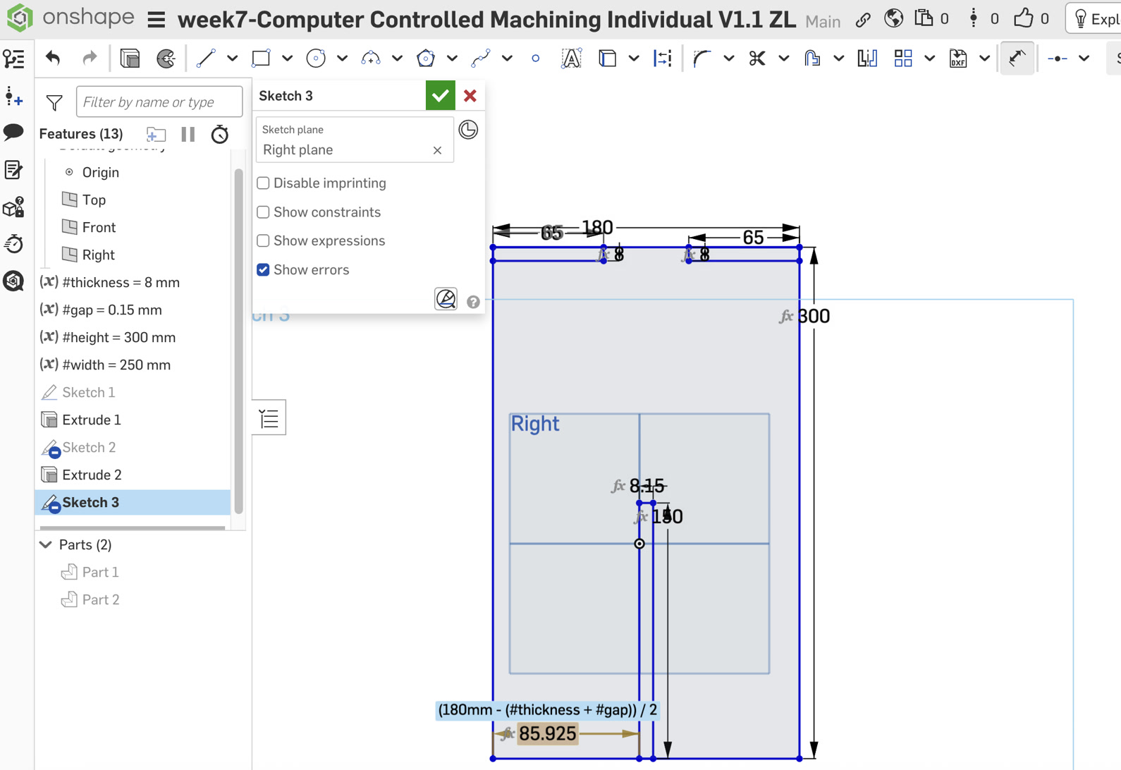
Extrusion: Finished with Extrude New at #thickness.
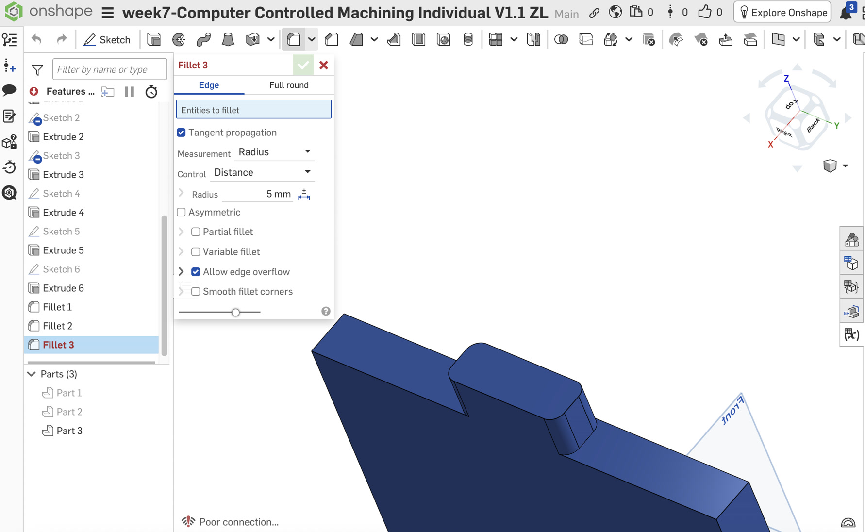
5. Implementation of Dog-bone Fillets
After finalizing the primary structures for all components, I performed a dedicated "Post-Processing" phase to add dog-bone fillets. I followed the assembly logic by processing the legs first and the seat last.
Leg A & Leg B: Slot-Base Pocket Relief
Since the legs are the core structural members, I began by adding relief to their interlocking slots.
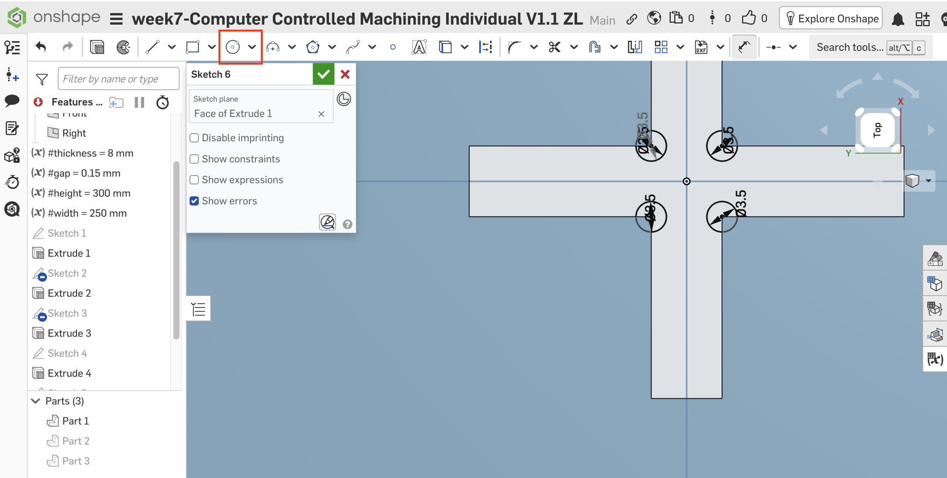
Locating the Sketch Plane: For both Leg A and Leg B, the dog-bones must be placed at the "dead end" of the slots. I rotated the 3D model to select the narrow rectangular face at the very base of the slot (the 8mm x 8.15mm plane).
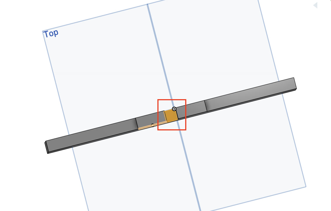
Internal Corner Sketching: On this small plane, I started a new Sketch. I zoomed in closely to capture the two internal corners where the slot floor meets the side walls.
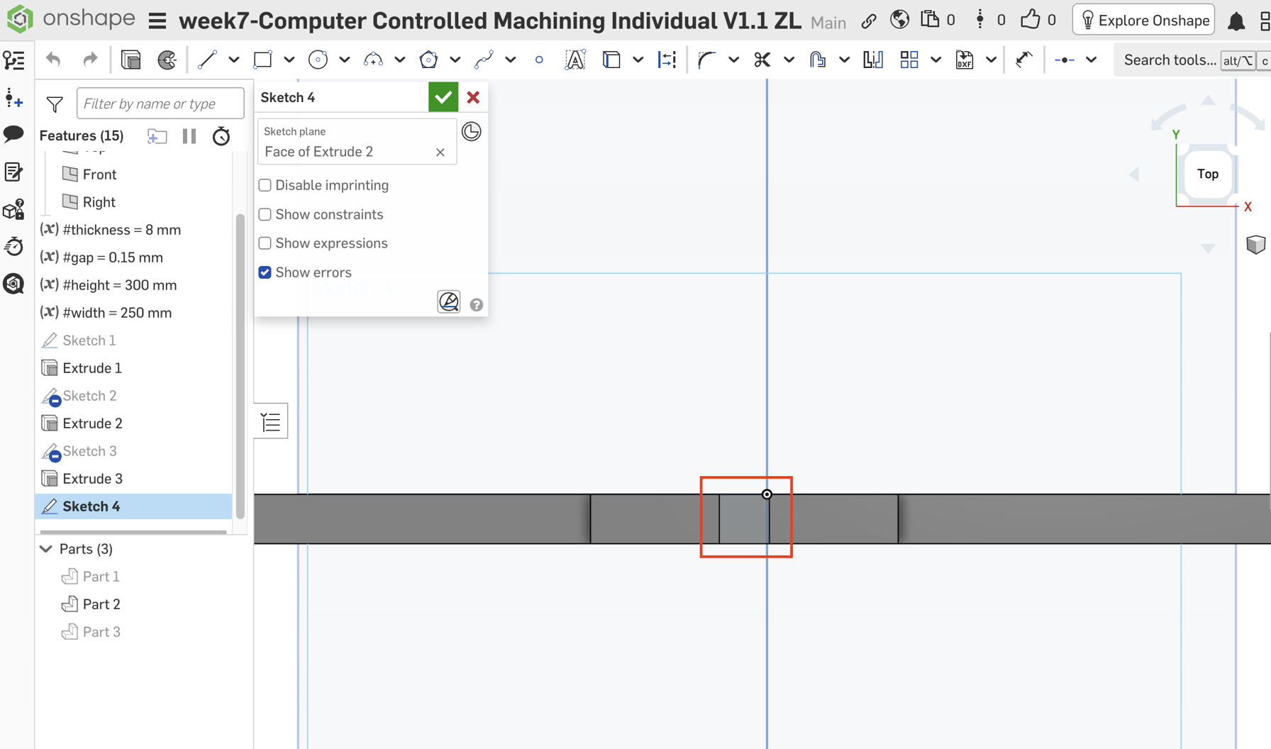
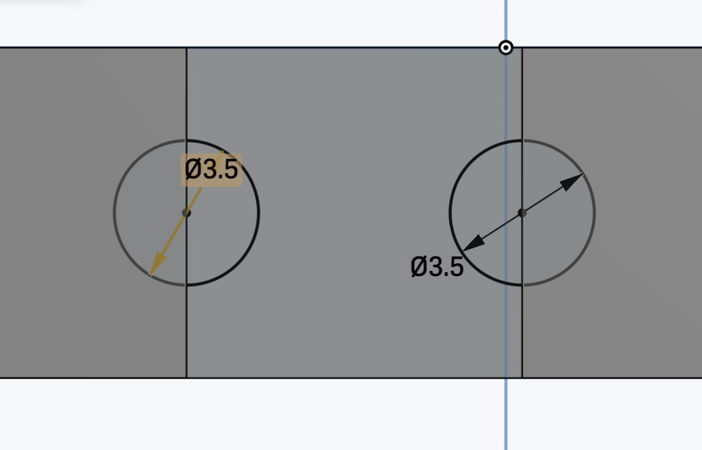
Precise Alignment: Using the Center Point Circle (C) tool, I drew two 3.5mm circles. I waited for the orange snap indicator to ensure the center of each circle was perfectly locked onto the corner vertex.
The dog-bone diameter was set to 3.5mm to accommodate a standard 3.175mm (1/8 inch) CNC end mill. In CNC machining, the relief hole must be slightly larger than the cutting tool to ensure the bit can fully enter the corner and clear out enough material. This extra 0.325mm of clearance guarantees that the sharp 90-degree corners of the mating parts can seat completely flush without being obstructed by the rounded edges left by the tool.
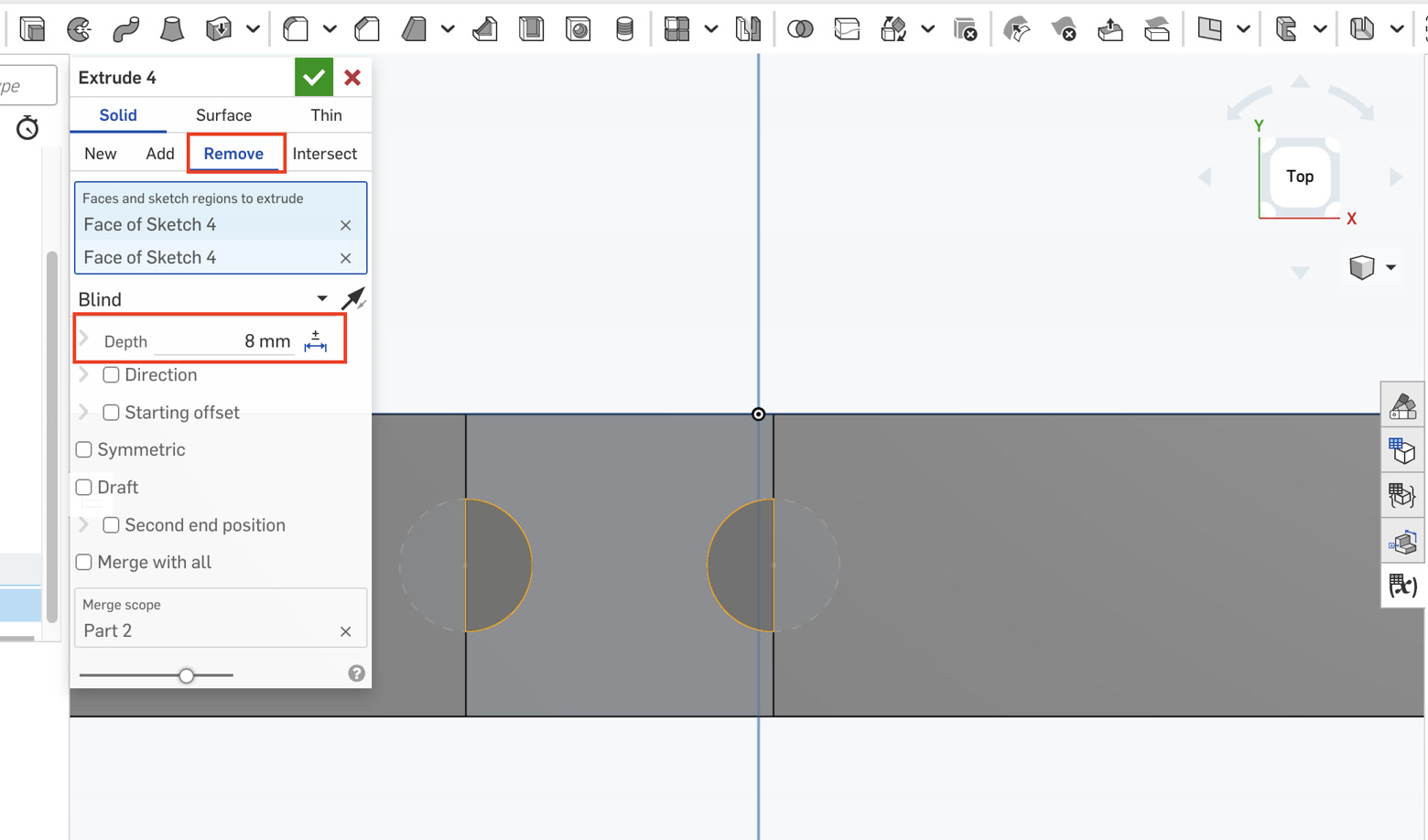
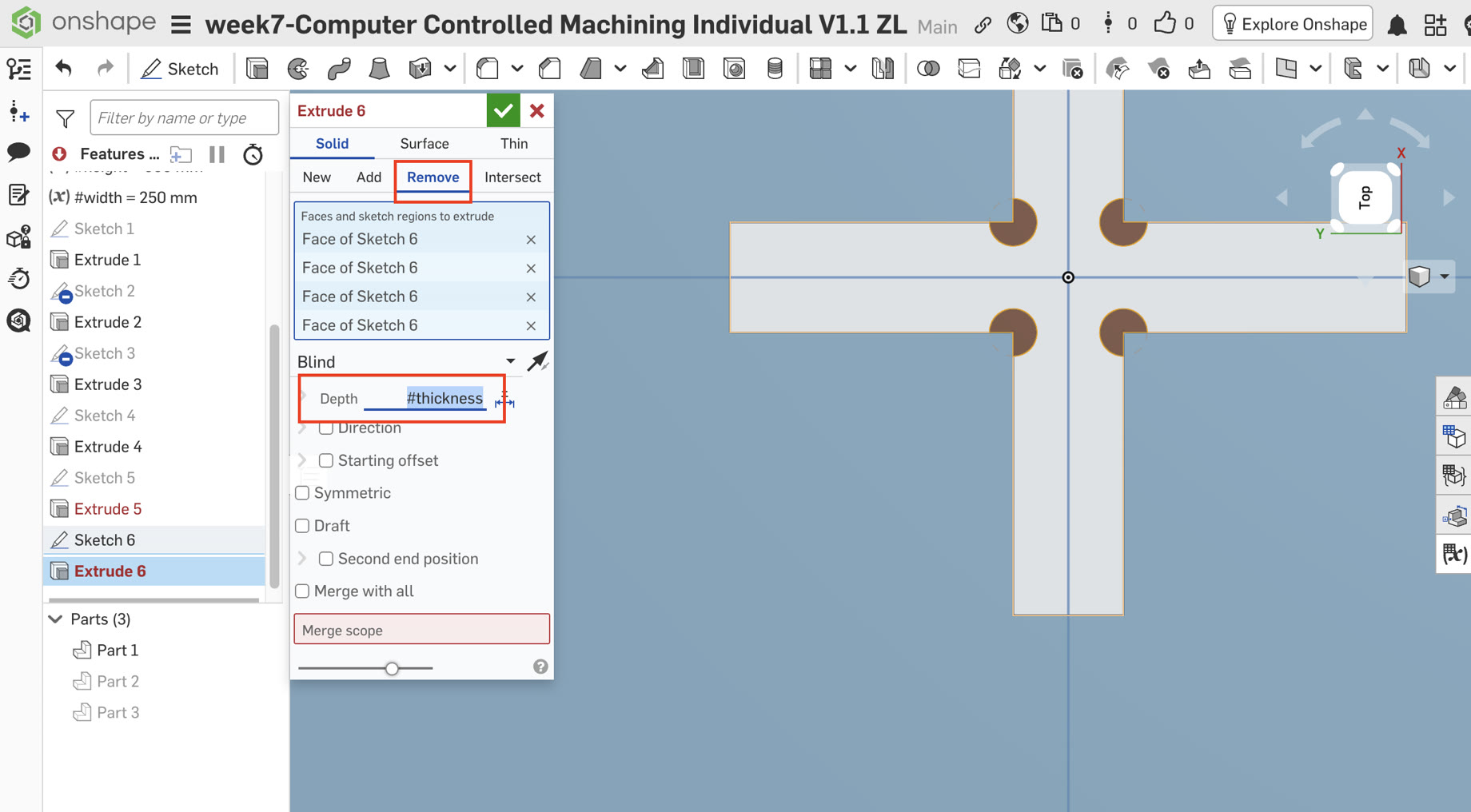
Execution: I applied an Extrude Remove operation to these circles. This resulted in two semi-circular "pockets" at the corner of the joint, ensuring that the sharp shoulder of the mating leg can seat fully to the bottom.
Leg A dog bone:
Leg B dog bone:
Seat: Vertical Through-Hole Relief
Once the legs were prepared, I moved to the Seat to ensure the combined "cross-tenon" could pass through it.
Surface Selection: I selected the top face of the Seat and created a new Sketch, then pressed 'N' to orient the view.
Vertex Snapping: I identified the internal L-shaped vertices of the cross-slot. I hovered the circle tool over these points until the orange square snap appeared, confirming the center was precisely on the corner.
Constraints: I drew the circles and used the Dimension (D) tool to set the first one to 3.5mm. I then selected all circles and applied the Equal (=) constraint to maintain parametric consistency across the entire part.
Material Removal: I finalized the step with an Extrude Remove command. I selected the circular regions and set the depth to the variable #thickness, creating vertical cylindrical channels through the board.
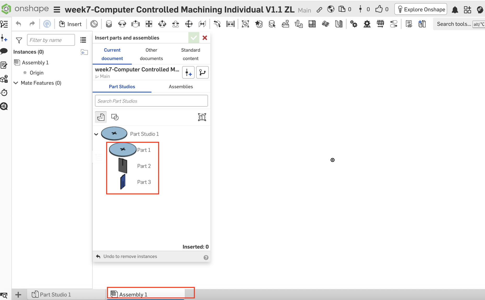
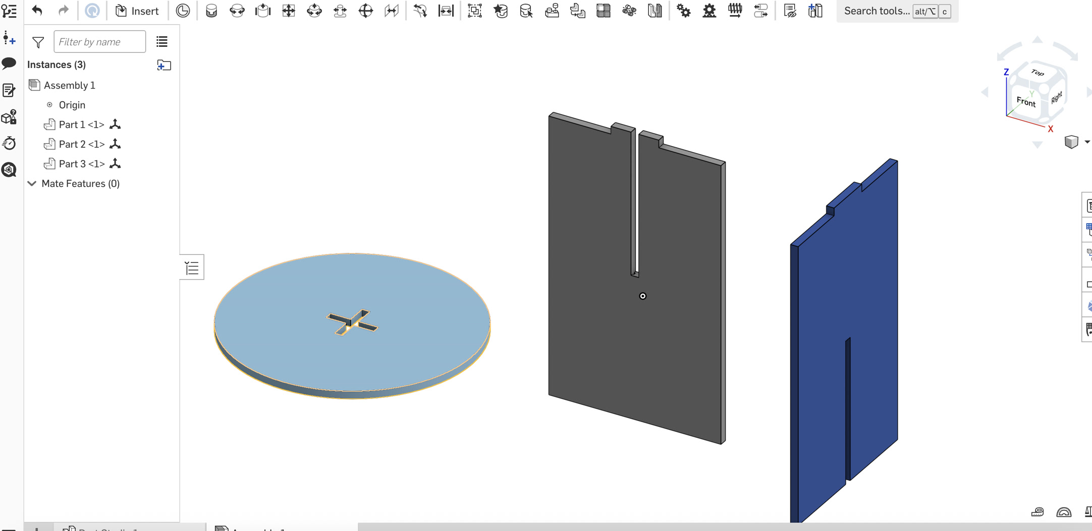
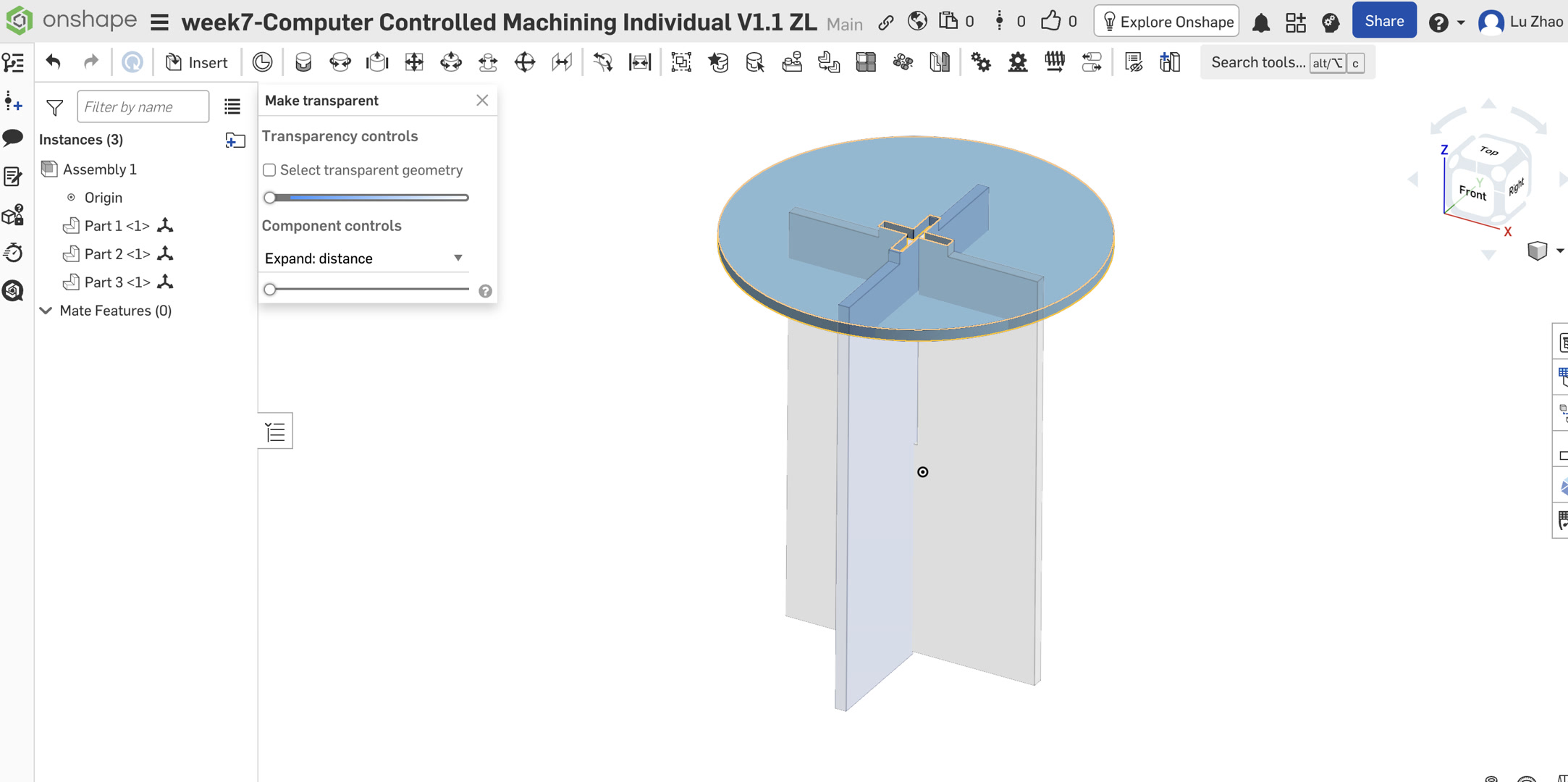
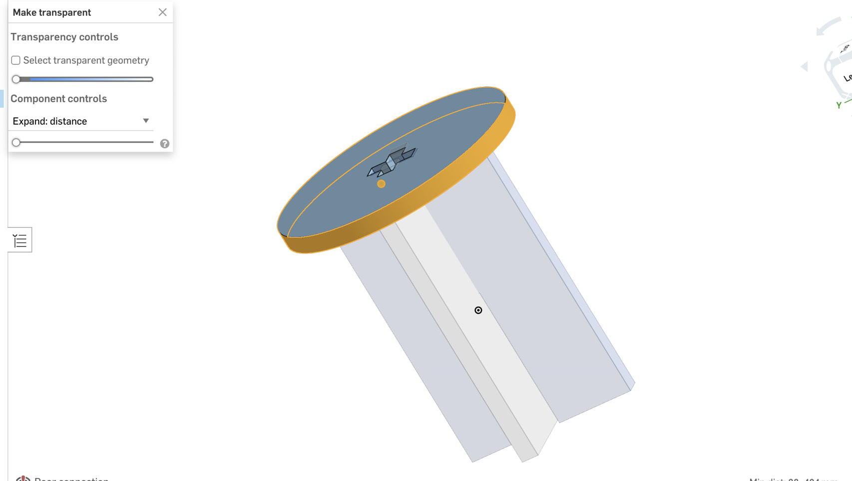
6. Assembly and Interference Check
Interference Check: I returned to the Assembly tab to inspect the fit.
Visual Confirmation: Using the Section View, I verified that the sharp 90-degree corners of the interlocking legs now occupy the "voids" created by the dog-bones. This confirms that the parts will achieve a flush press-fit during physical assembly, as the cylindrical tool path has been pre-cleared in the digital model.
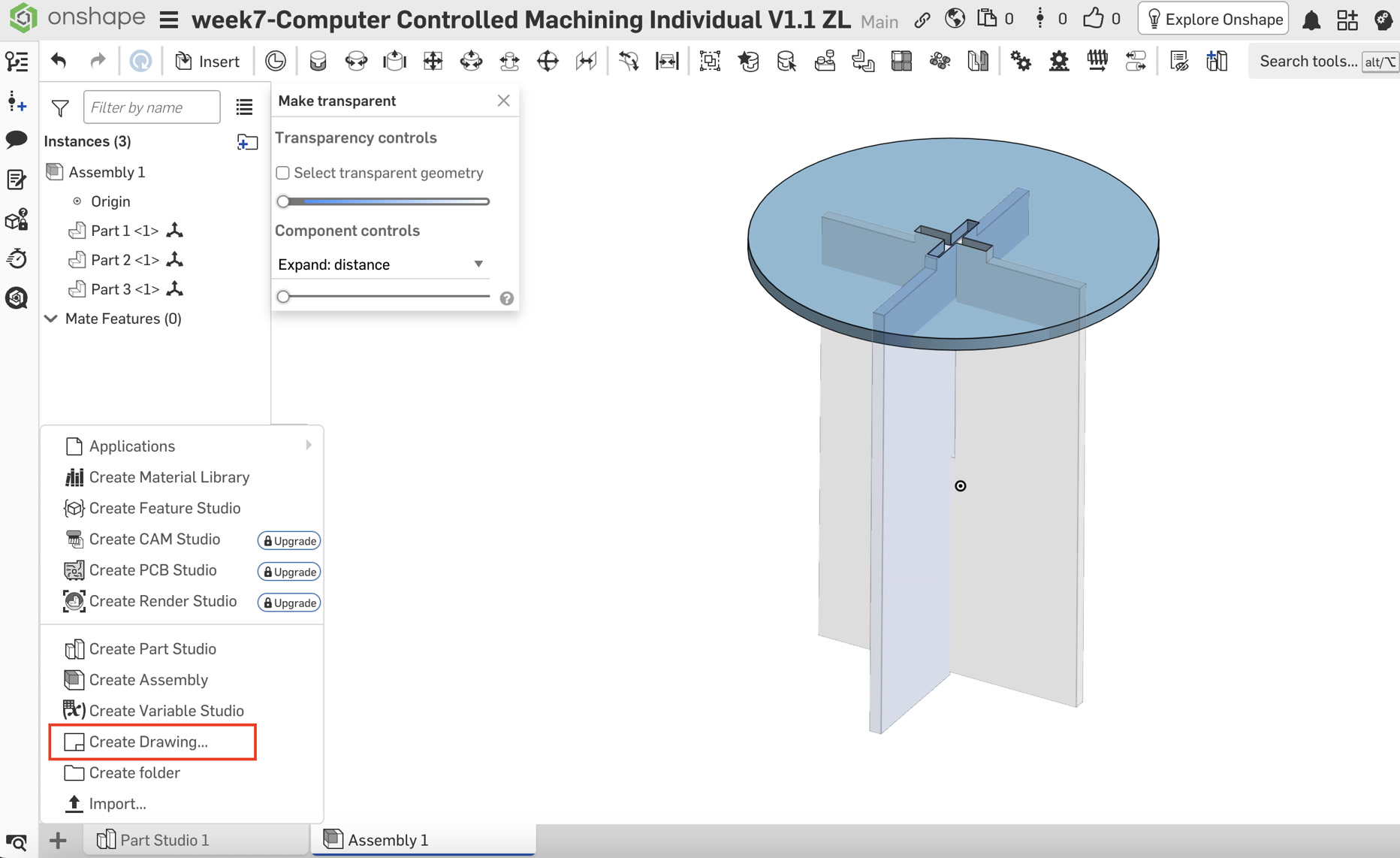
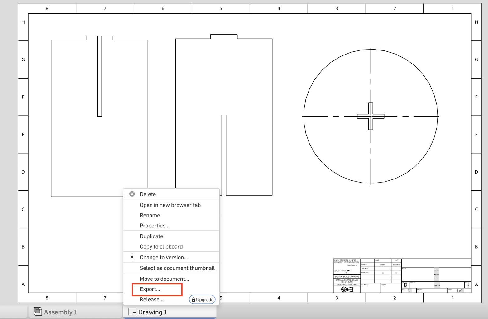
7. Exporting for Manufacturing (DXF)
To prepare for CNC cutting, all parts were flattened into a single production file:
Create Drawing: Created a new D-size Drawing with no borders or title blocks.
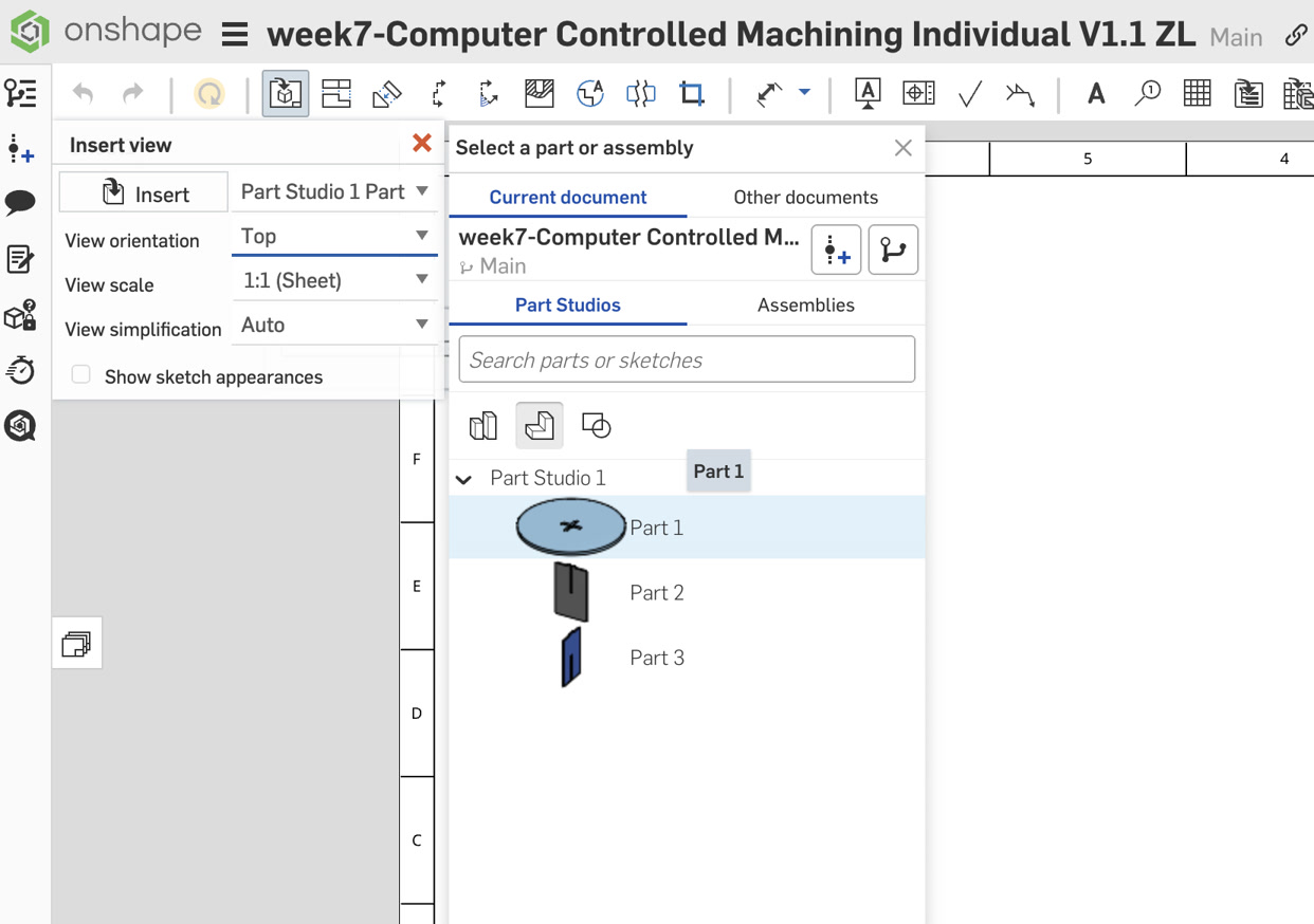
Inserting Views:
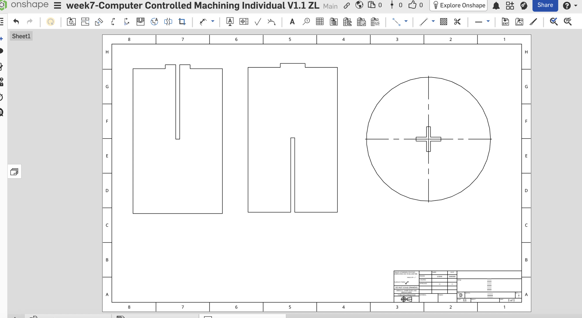
- Seat: Inserted the Top View at a 1:1 Scale.
- Leg A: Inserted the Front View at a 1:1 Scale.
- Leg B: Inserted the Right View at a 1:1 Scale.
Nesting: Arranged the parts on the sheet with at least 20mm clearance between them.
Export Settings:
8. Conclusion
The final DXF file is a 1:1 vector representation of the 3D model, ready for CAM software. The parametric nature of the design allows for rapid adjustment if a different plywood thickness is used.
Before CNC cutting, I double checked the material parameters and just realized that the thickness of board is 18mm, not 8mm. Since I had variable table, it made it much easier to change this diameter. Then all the related parameters are changed accordingly.
Also, as per our instructor, the diameter of the end mill is 8mm, not 3. So, I changed the circle diameter to 9mm for the dog bone.
I exported the updated DXF file again with the updated #thickness diameter.
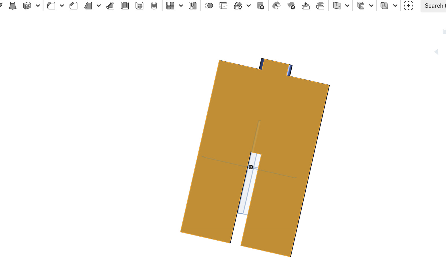
Update:Before finishing the design, I just tried one more thing--for the cross slot of stool surface, and the connection parts of leg A & leg B, the dimension is totally the same. According to other Fab Academy fellows' suggestion, if the slot and tab are designed with exactly the same dimensions, assembly can be difficult because of machining tolerances, material thickness variation, cutting kerf, and friction between parts. Thus, I finally added the fillet on the tabs of leg A and leg B, of 5mm radius.
DXF file:
Part Studio 1 - stool.dxf Part Studio 1 - Leg B.dxf Part Studio 1 - Leg A.dxfMasterCAM Setting to generate G-code
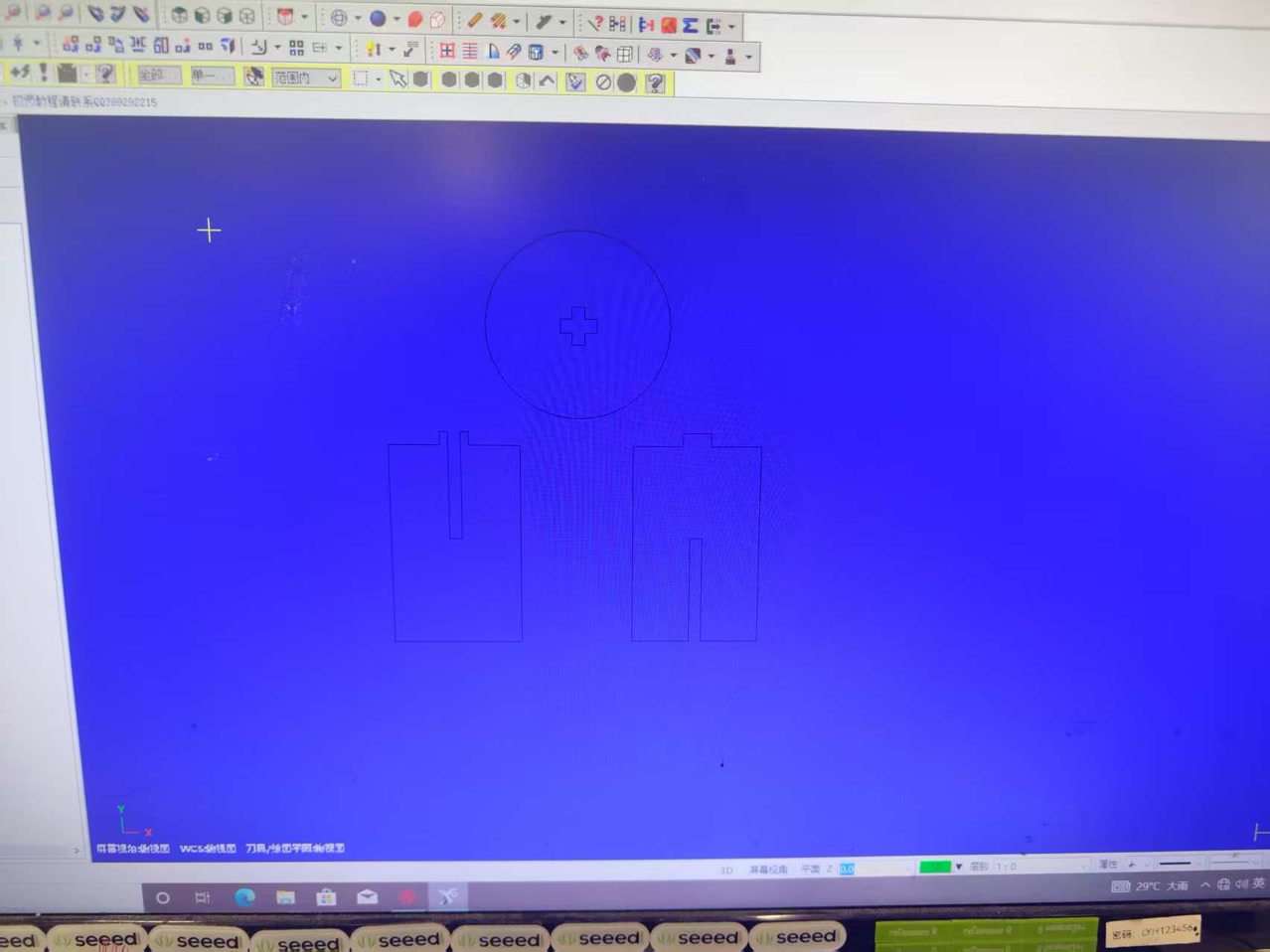
DXF File import:
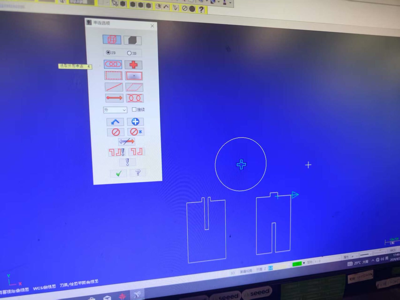
I imported the DXF file to the MasterCAM to confirm settings for next CNC cutting. First drop the parts which shall be cutted to the sheet.
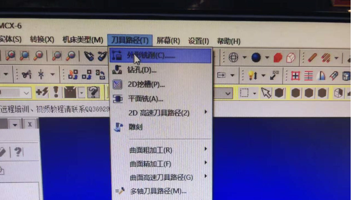
For a press-fit stool, we primarily use Contour (Profile) toolpaths:
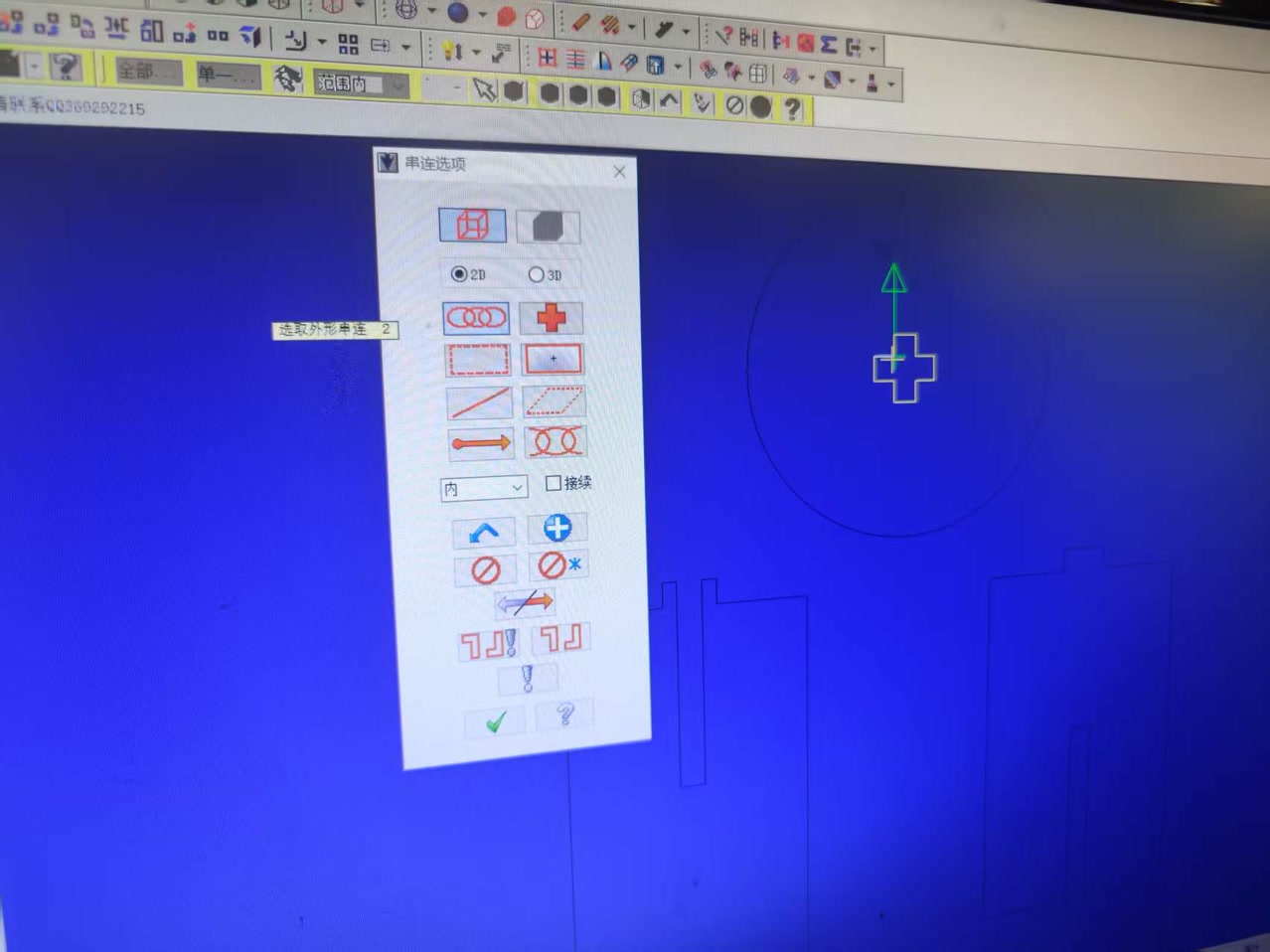
- Inner Slotted Cuts: Select the internal slots first.
- Outer Contour: Select the overall perimeter of the parts. Toolpaths were arranged using an “inside before outside, small before large” strategy: internal features and smaller areas were machined first, followed by the outer contours to keep the material stable for as long as possible.
Settings for the innerside first. For all 3 parts to be cutted, the only innerside part is the cross-shaped slot inside the stool surface. I discussed with our instructor-if not cutting the cross first but cutting the circle edge instead, when cutting the cross slot, the force applied to the tool head will cause the stool surface to rotate, preventing the correct cutting of the cross-shaped slot.
When configuring the toolpath, the following parameters are the most vital:
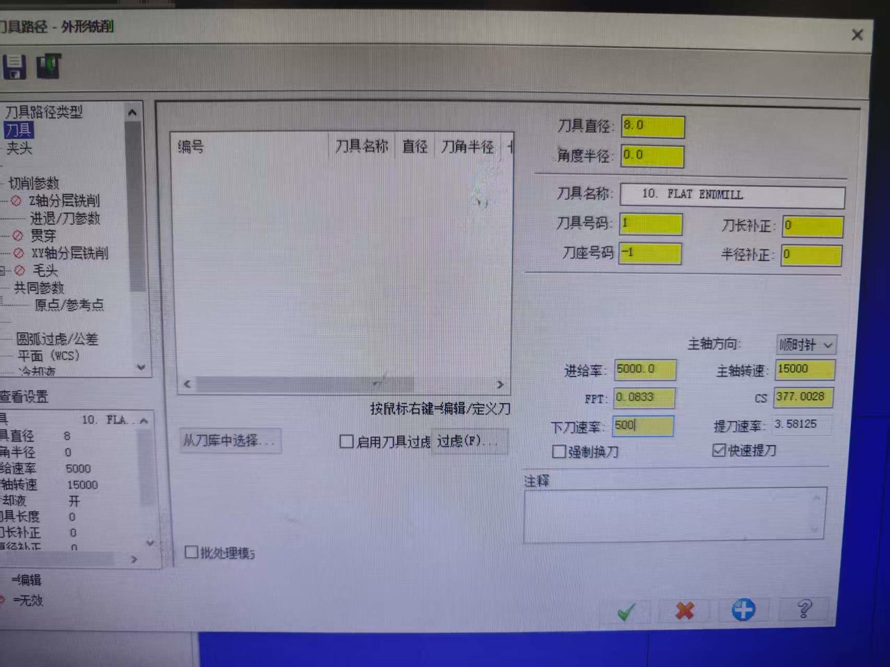
- Tool Definition: Specify the 8mm Flat End Mill. It defines the geometry of the tool so the software can calculate the correct offset.
- Spindle Speed (15,000 RPM): It is the rotational speed of the bit. High speeds are needed for clean cuts in plywood.
- Feed Rate (5,000 mm/min): It means how fast the machine moves horizontally through the wood.
- Plunge Rate (500 mm/min): The speed at which the bit enters the material vertically.
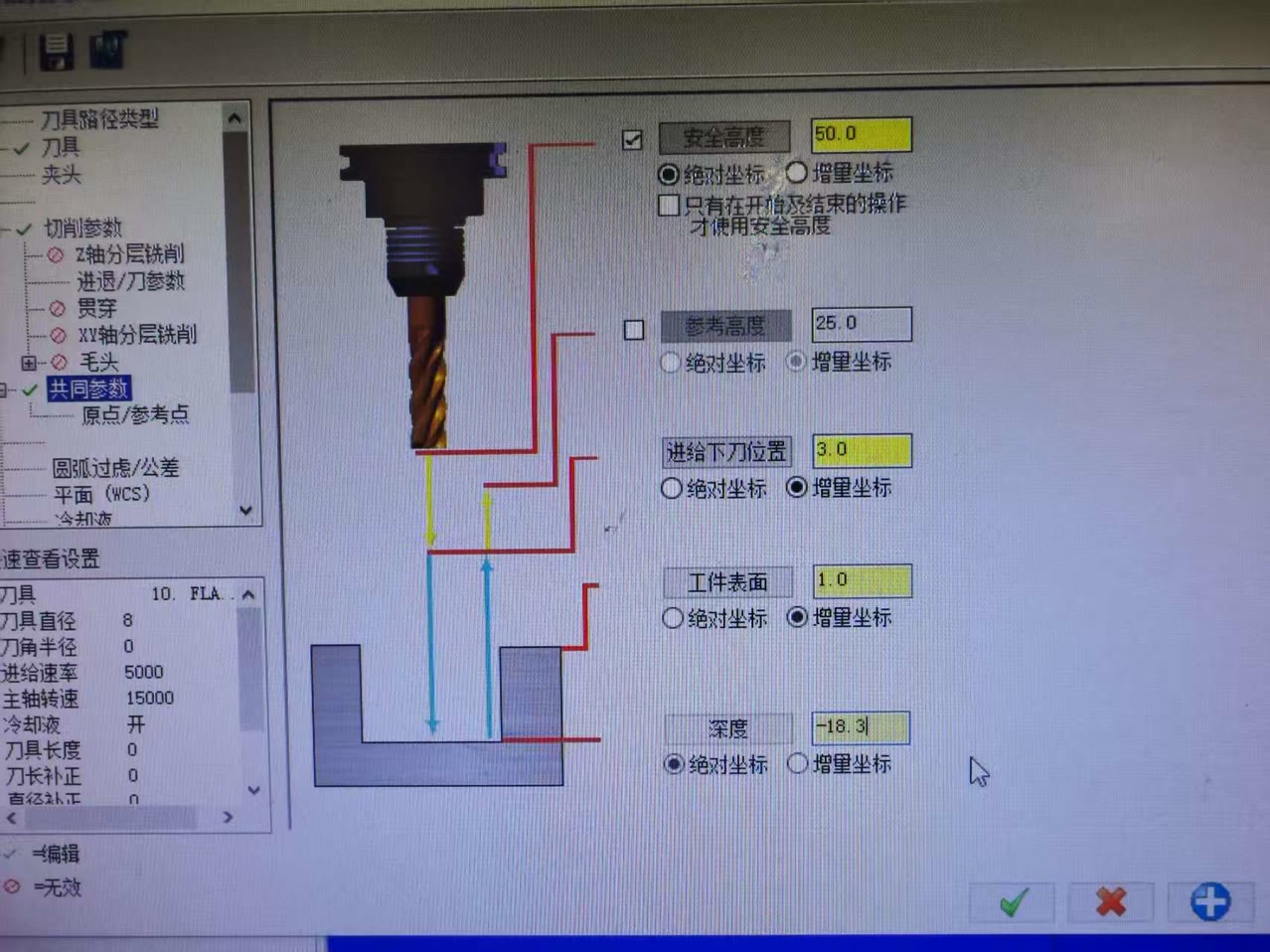
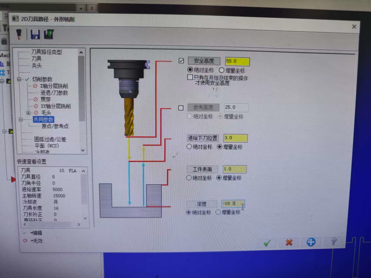
- Depth Cuts (Stepdown: 18.3mm): The maximum depth the bit cuts in a single pass. For the 18mm board, we set the parameter to 18.3 to make sure the tool can successfully cut to the bottom of board.
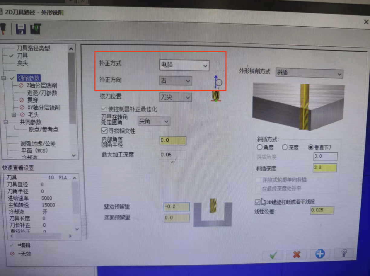
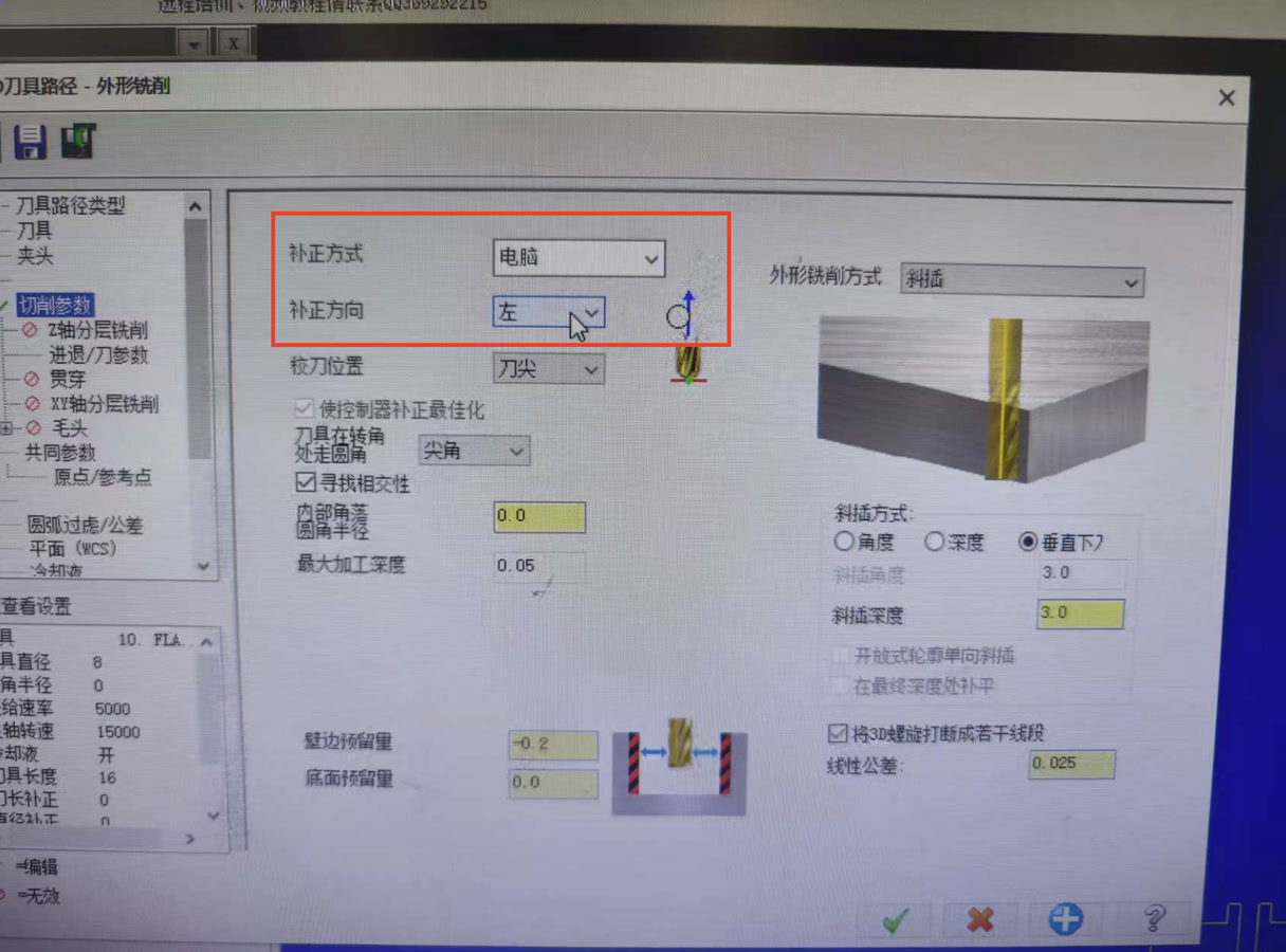
- Lead In/Out: Adds a small radius or tangent line to the start/end of a cut so the bit doesn't leave a "witness mark" on the final edge.
It tells the machine to stay on the Outside (for perimeters) or Inside (for slots) of the line. This accounts for the 8mm diameter of the tool to ensure the final part dimensions are accurate.
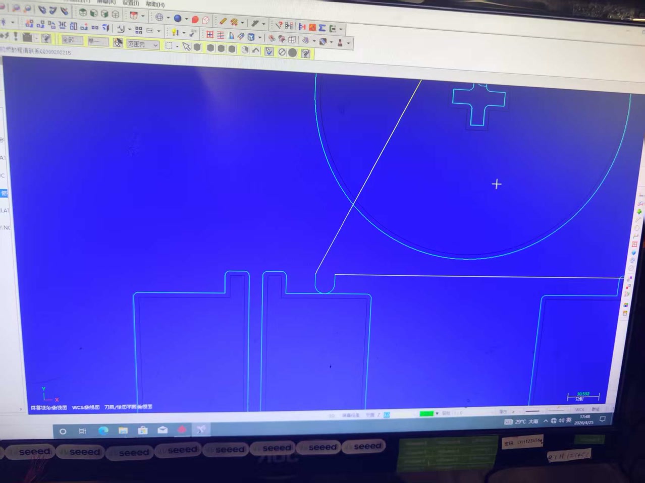
After the settings of innerside, we can see the toolpath of the cross slot on stool surface.
Then we did the settings for the outside. We selected the outer lines, which included the outer circle of stool surface, the entire path leg A and leg B.
After finishing the settings for both inner and outer, I can see the path for all 3 parts. I converted the toolpaths into a .nc file (G-Code) that the CNC controller can execute.
G-code file:
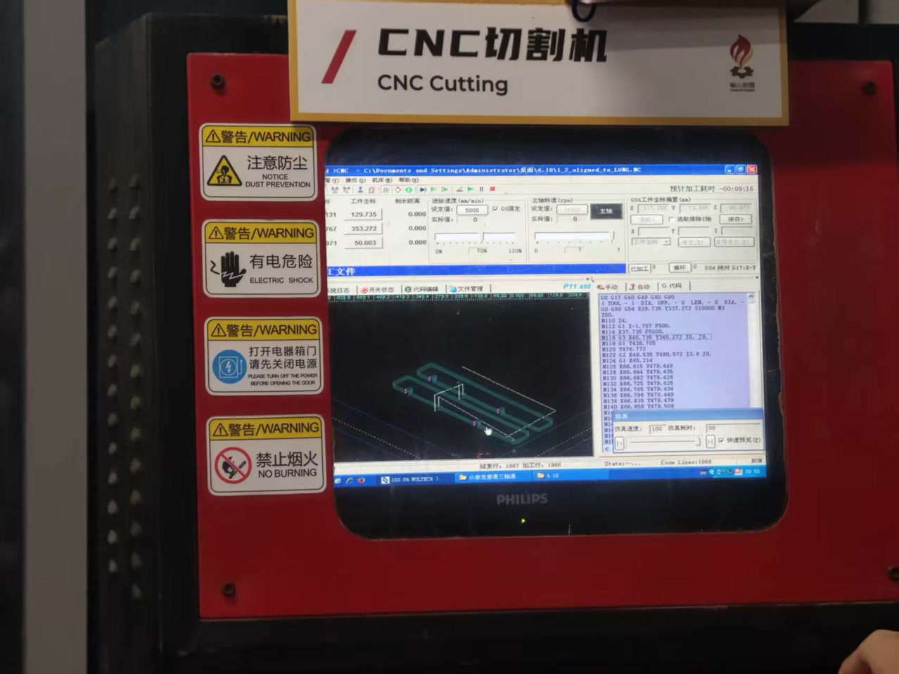
SUNNY stool GCODE for CNC.NCSettings on CNC Machining
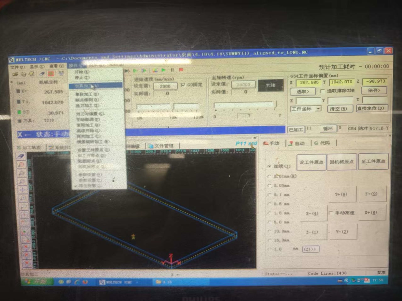
Once the layout and toolpaths were verified, we established the machining origin so the machine could correctly reference the starting positions of the X, Y, and Z axes relative to the workpiece.
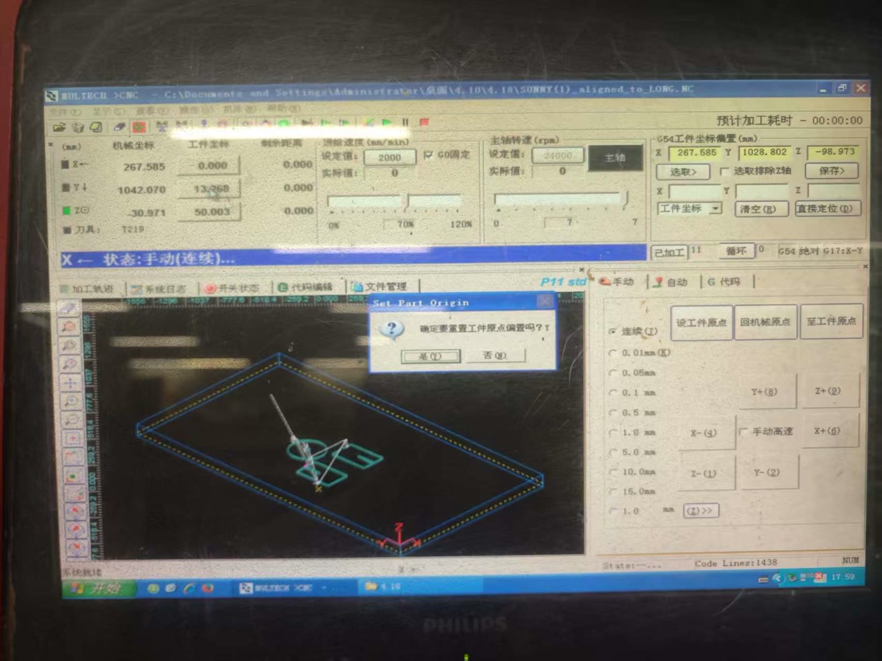
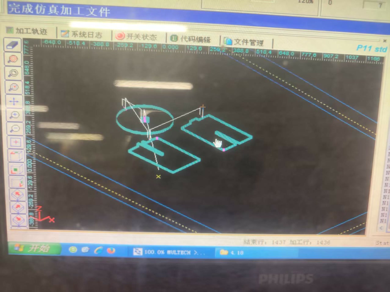
I selected "simulation processing", then we saw the tool path for these workpieces.
CNC Cutting
During the cutting operation, we followed the sequence below:
- Positioning: Place the board onto the machine table.
- Fixing: Secure the material firmly to prevent any movement during the machining process.
- Zero Setting: Adjust the work origin so it matches the coordinates defined in the CAM setup.
- Dust Control: Turn on the air or dust collection system (and any required extraction) to manage chips and dust.
- Program Check: Verify the selected program and machine settings on the controller before starting the job.
- Monitoring: Watch the cutting process continuously. If a small part separates from the main sheet before the outer contour is finished, pause the machine (we used F10), wait until the spindle has completely stopped, and then remove the loose piece. Only handle parts when the machine is paused and the tool is no longer rotating.
- Cleaning: After the job is completed, clean the working area, remove chips, inspect the spoilboard, and leave the machine ready for the next user.
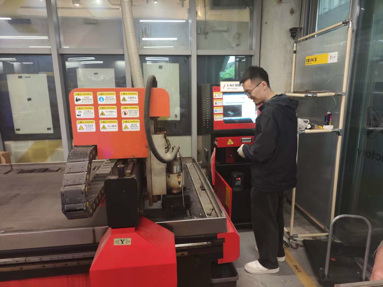
After we ensure every step can be secured, I started the cutting process on CNC.
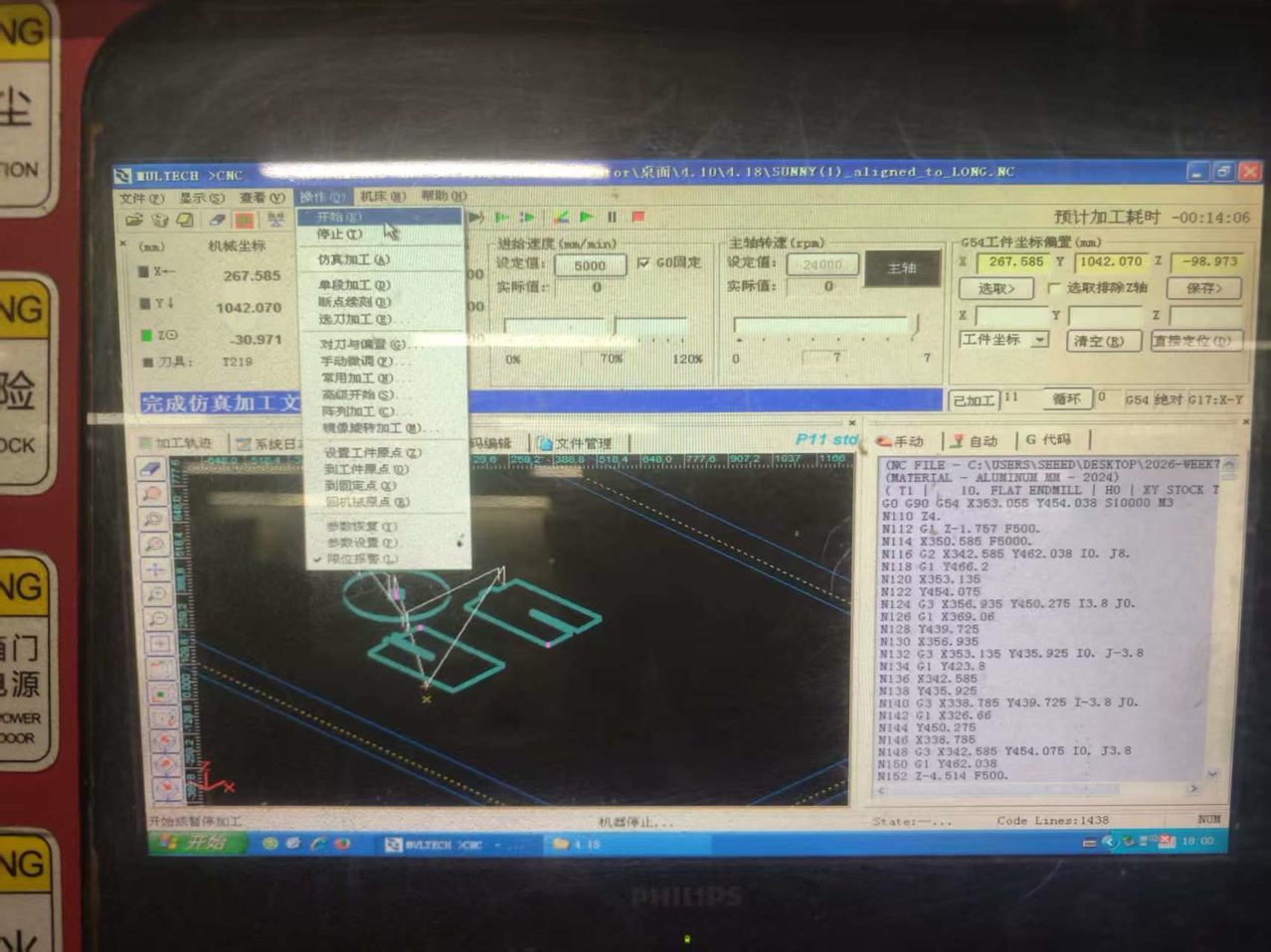
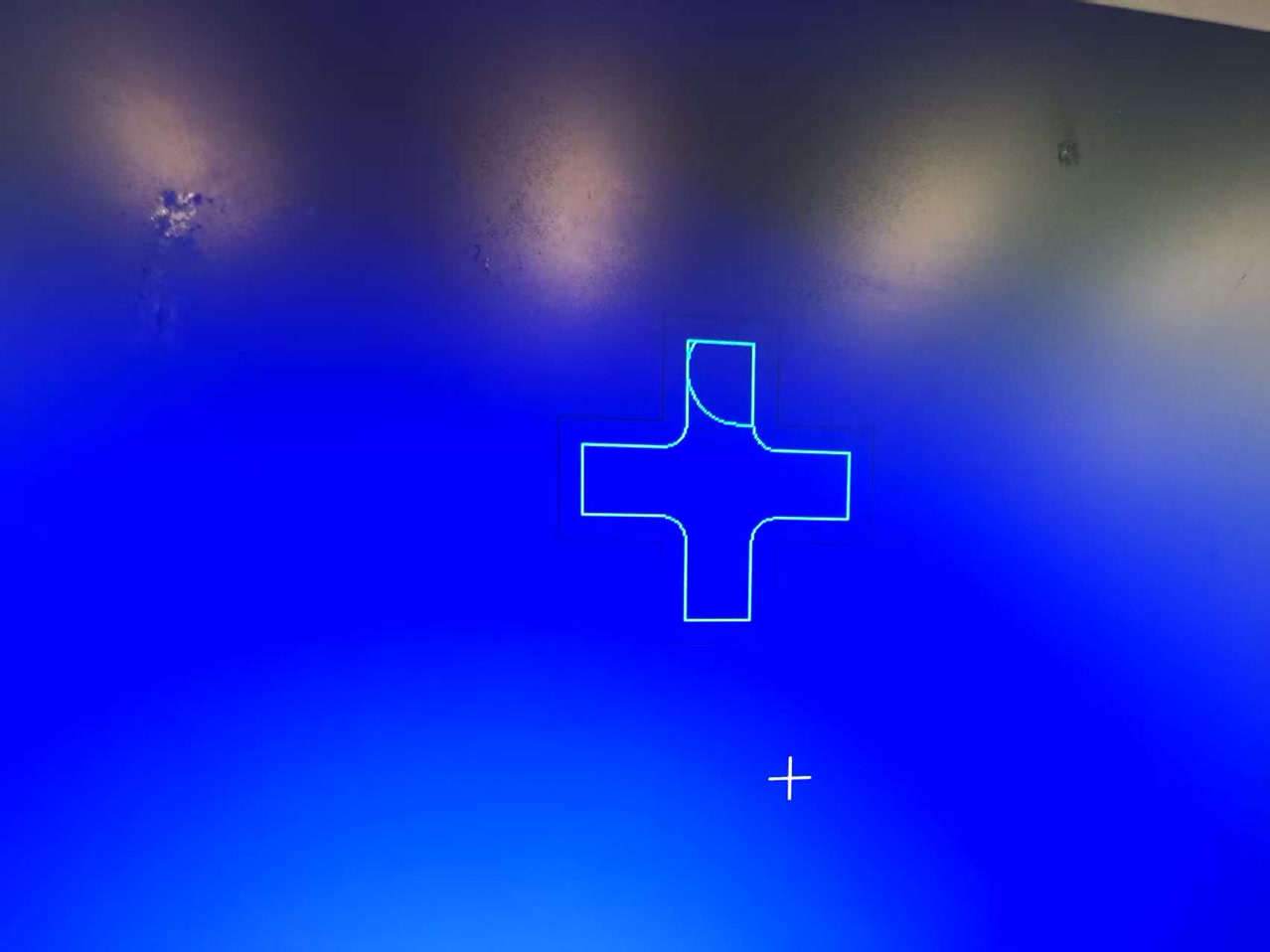
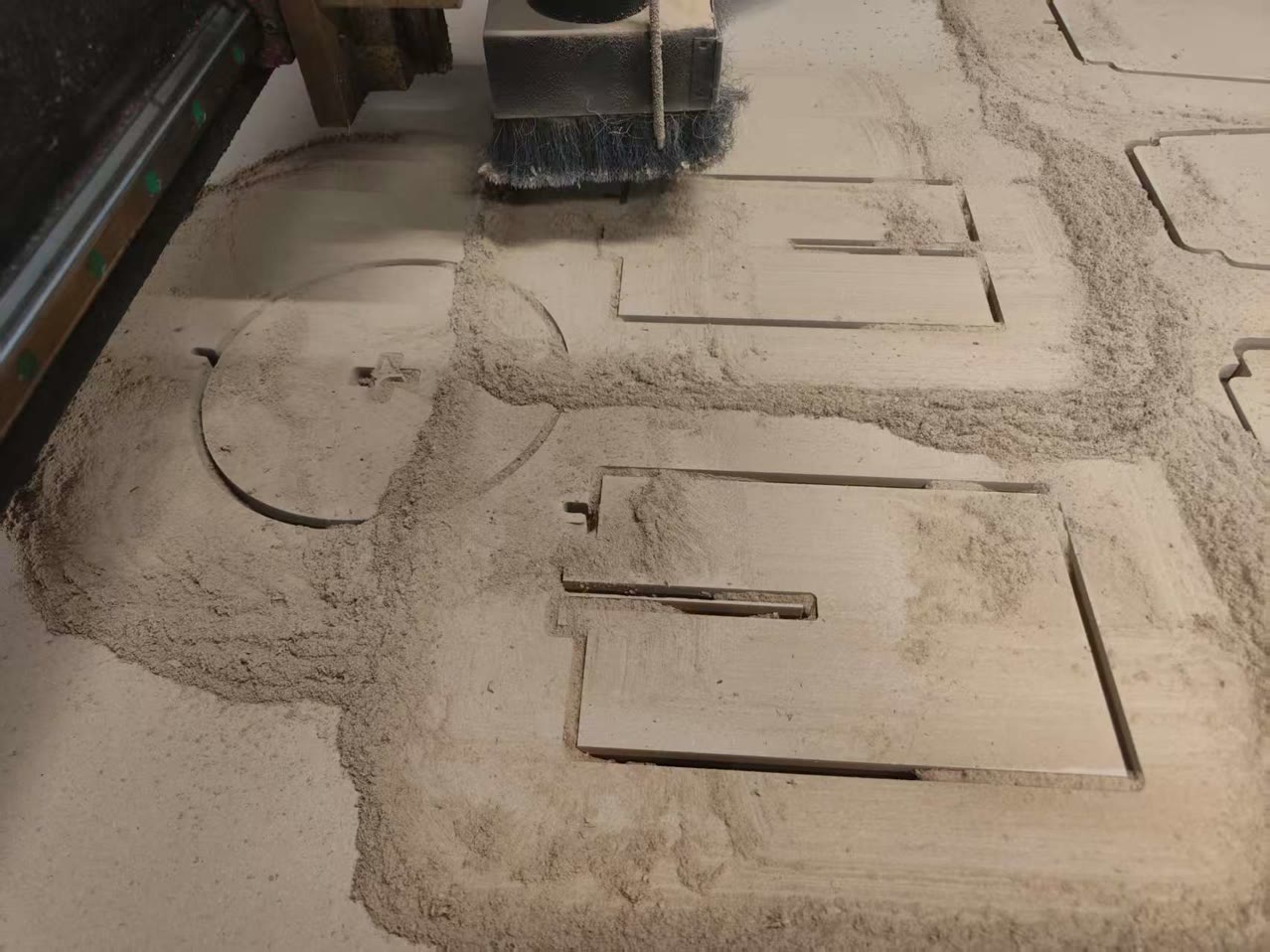
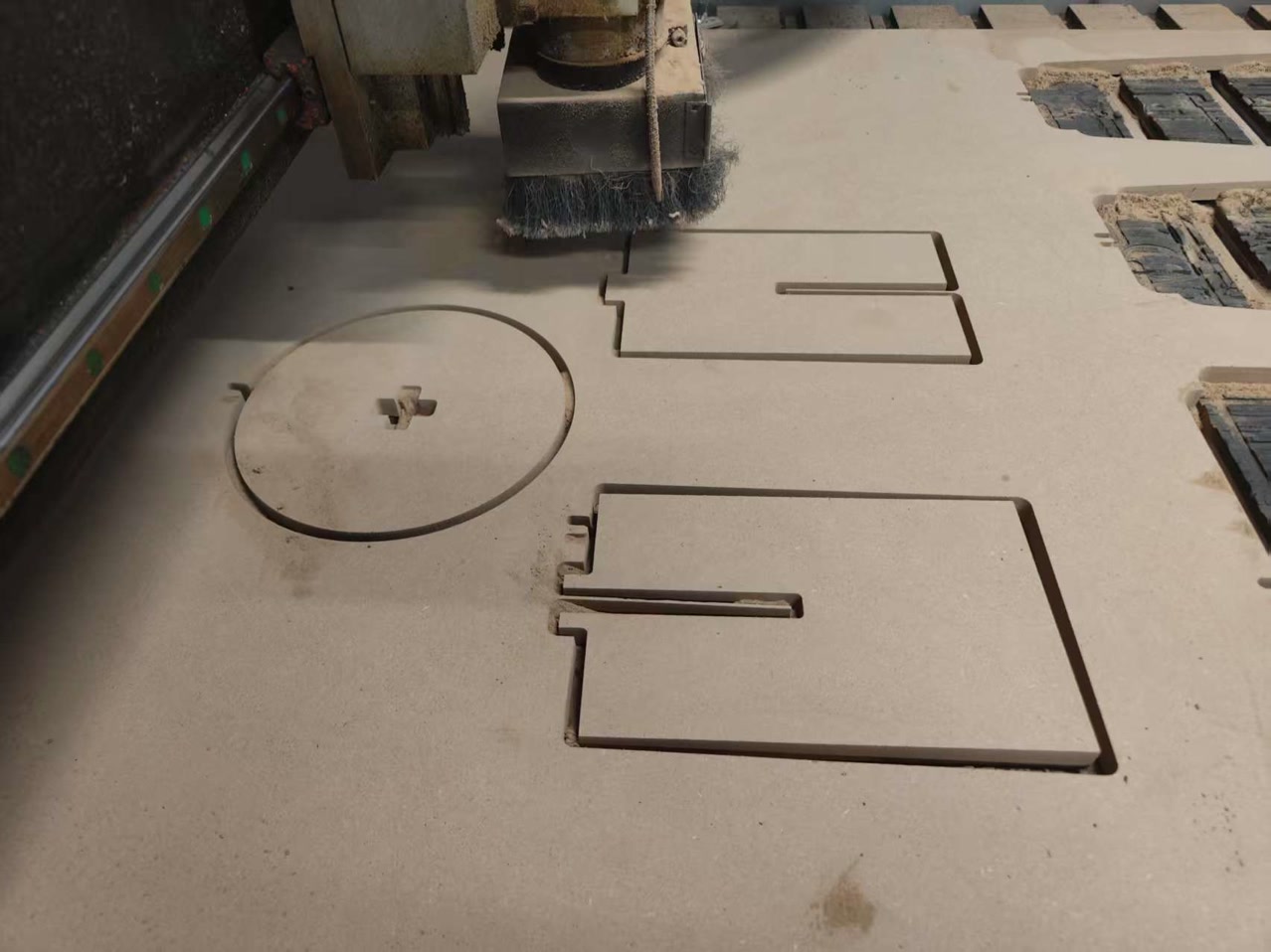
CNC machine is cutting from the the stool surface now:
It only took about 13 minutes to finish the cutting. Now the physical parts are ready!
Stool Assembling
Since our dust extraction equipement is not working today, I used the vacuum cleaner to remove all the dusts generated from board cutting.
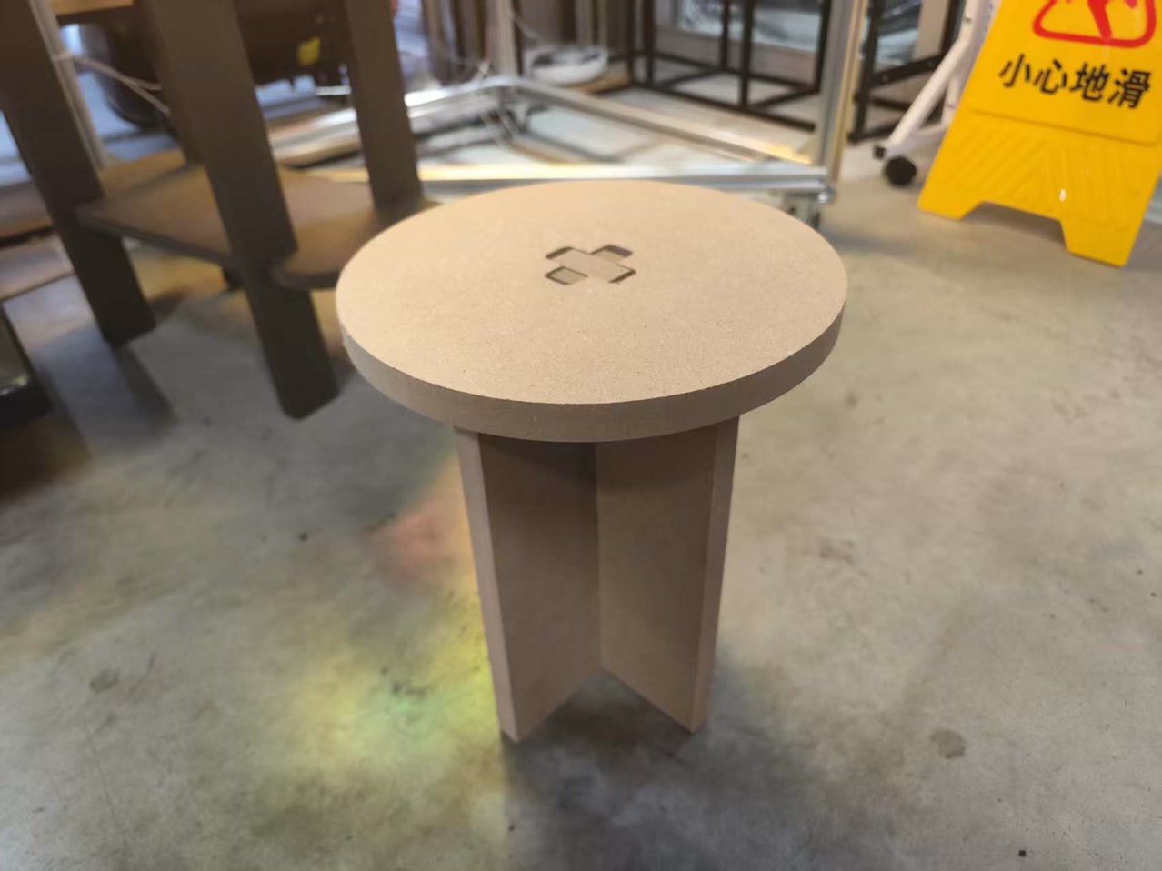
I checked the parts to see if there's any tear-out, tabs, and if the slots on stool surface, leg A & leg b, and corners could match my design. Then I integrated all the parts together, then I have my first designed CNC stool.
As a whole, the stool is quite stable, I can sit on it.
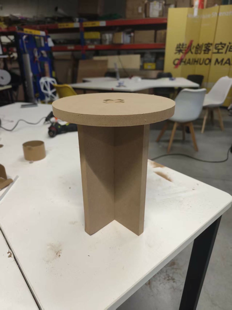
I found one problem:
The tabs from 2 legs does not match the press-fit of the cross slot on stool surface.
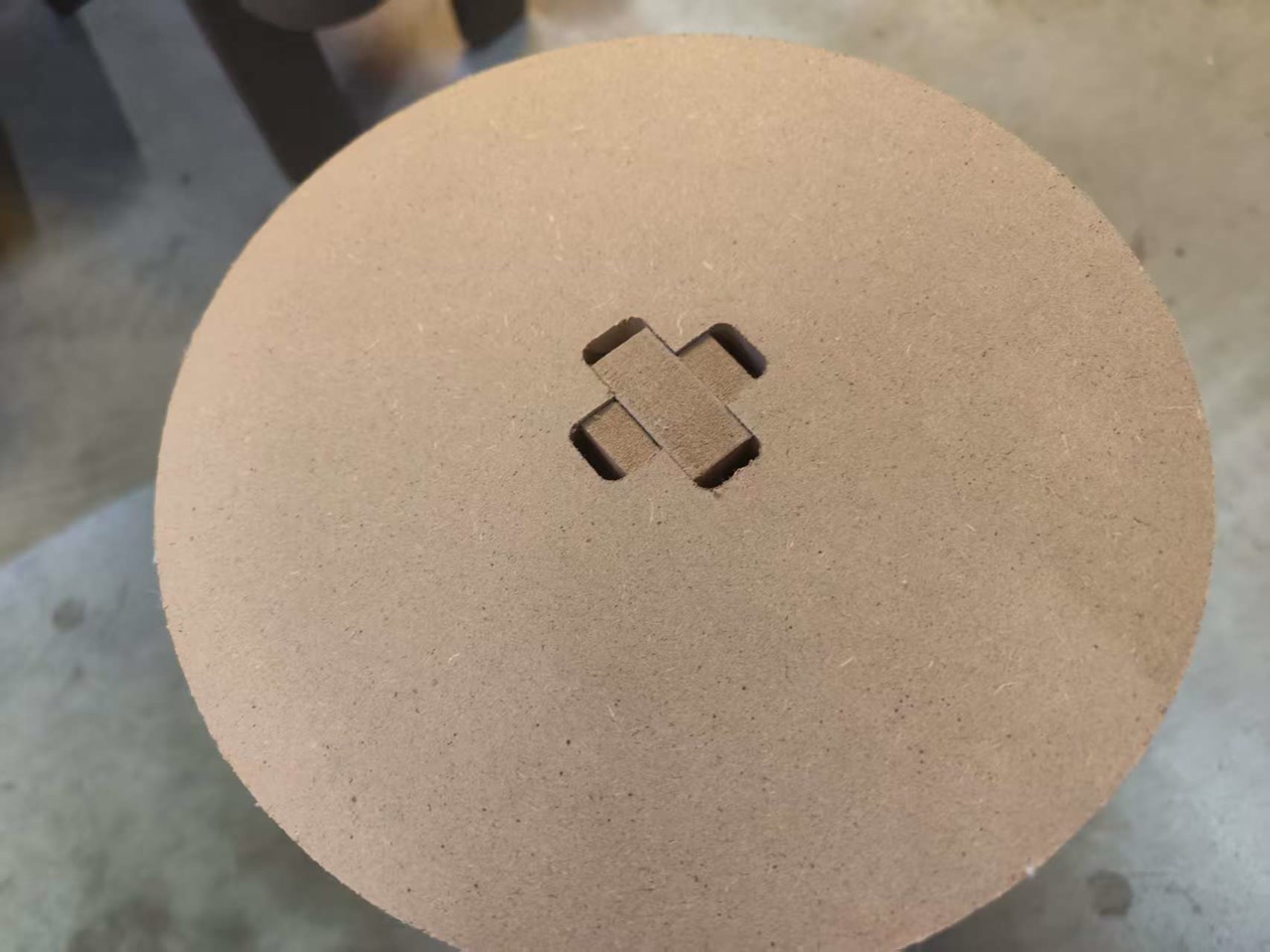
I checked the reason. It's because the fillet radius is 5mm of each corner, once I exported the DXF file (2D), it only recognized the flat surface onside, which is 50mm-5mm-5mm=40mm. So, in total, I lost 10mm on each tab. If I made a 1-2mm fillet radius, it would be much better.
Learning Summary & Reflection
- Parametric Design: I learned that building models with variables (like #thickness and #gap) is essential for CNC projects to quickly adapt to actual material measurements.
- Machine Characterization: Through group testing, I understood how to determine the actual kerf and runout of the machine to achieve a perfect press-fit.
- Tooling Logic: I discovered that selecting the right bit (e.g., an 8mm flat end mill) is a balance between material thickness, structural rigidity, and heat management.
- Joint Clearance: I mastered the use of dog-bone fillets to compensate for the circular nature of the cutting bit, allowing square parts to fit into internal corners.
- Design for Manufacturing (DfM): I realized that aesthetic fillets on joints can accidentally reduce contact surfaces and loosen the fit, as seen when my 5mm fillets "ate" 10mm of joint width.
- CAM Workflow: I learned to prioritize cut order (inside before outside) and use tabs to keep parts stable and safe during the final stage of machining.
- Safety & Precision: I gained hands-on experience in XYZ zeroing with a touch probe and learned that constant monitoring is the most effective safety protocol.