Week 3: Computer-Controlled Cutting
Group Assignment: Laser Cutter Characterization & Calibration
This week, our group collaborated to calibrate the industrial laser cutter specifically for 3mm Basswood. The core objective was to determine the Kerf (the amount of material removed by the laser beam) to ensure precision in future press-fit joinery.
1. Machine Specifications & Safety Protocol
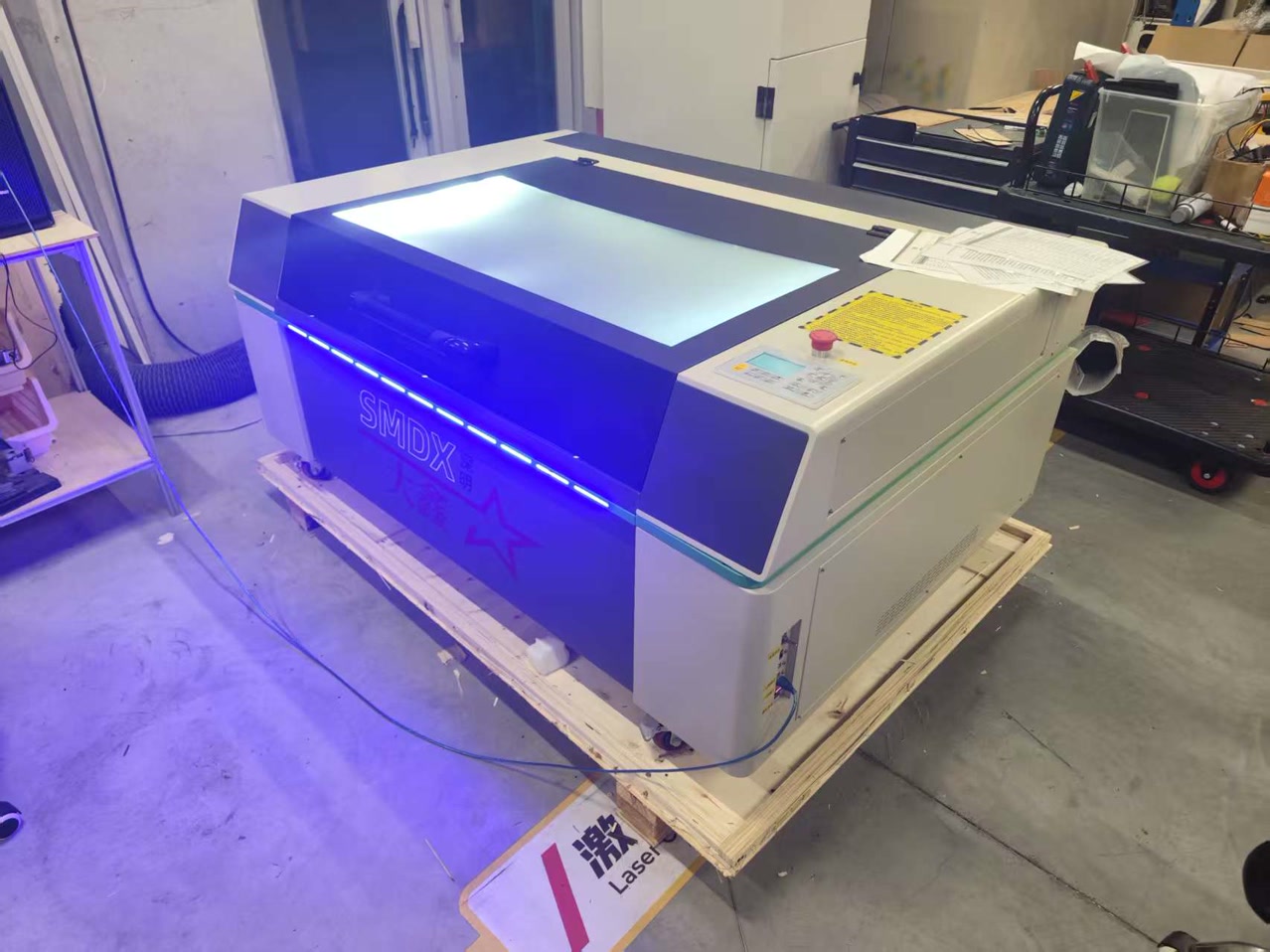
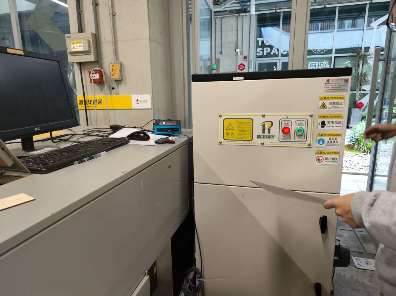
We I used a professional CO2 laser cutting machine from SMDX (深明大鑫) at Chaihuo Makerspace.
As a beginner, I followed a strict safety and preparation SOP:
-
Specifications: Work area of 1300mm x 900mm (providing ample space for large-scale nesting)., laser power 80-100W, and controlled by SmartCarve or RDWorks software.
-
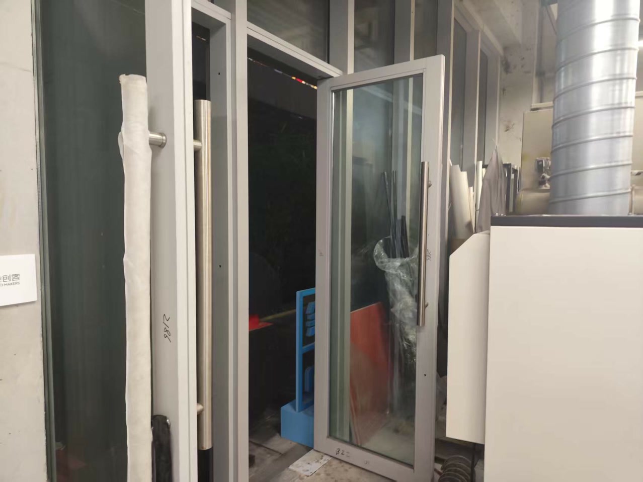
Ventilation: I ensured the doors were open and the exhaust fan was active to remove hazardous smoke and dust.
-
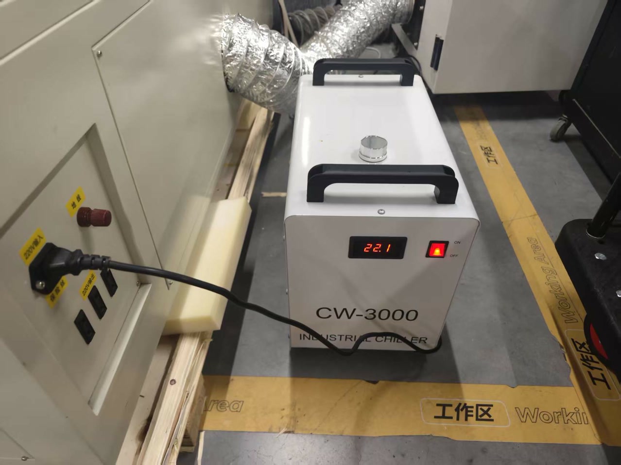
Cooling: I confirmed the water chiller was functioning to protect the laser tube from overheating.
-
Air Assist: I verified the air compressor was blowing through the nozzle to prevent the 3mm Basswood from catching fire during the process.
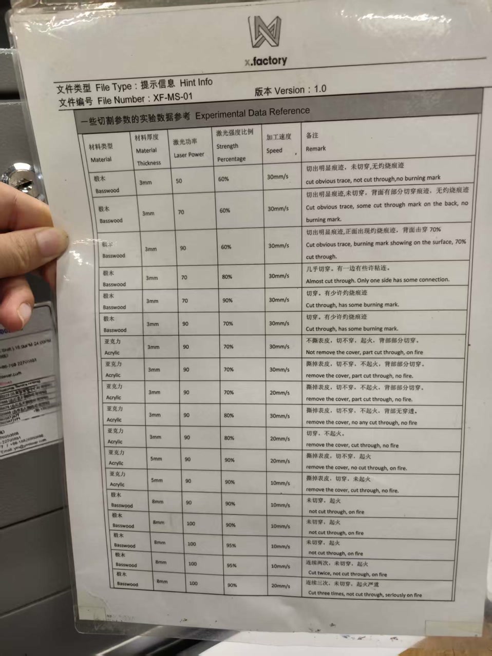
I read the guidance of the settings for different kinds of cutting materials.
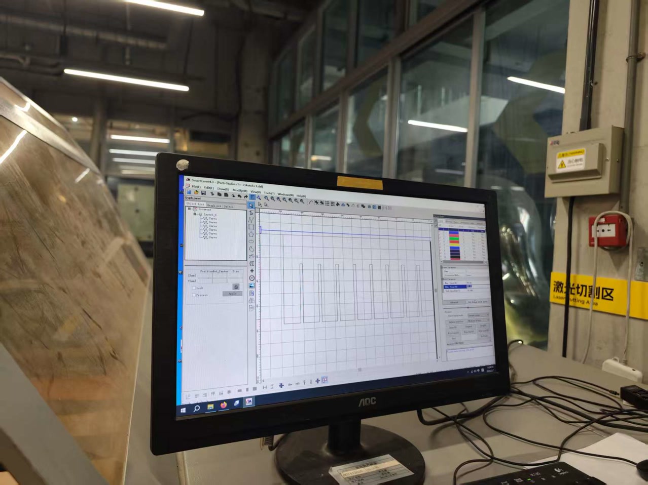
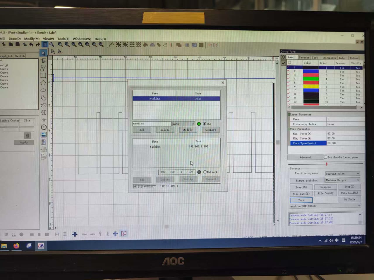
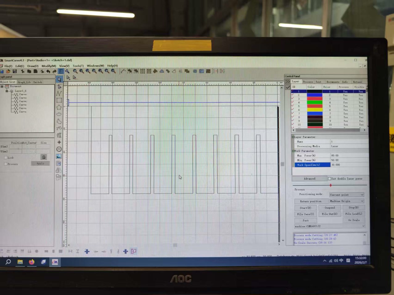
2. Software Workflow & Production (SmartCarve 4.3)
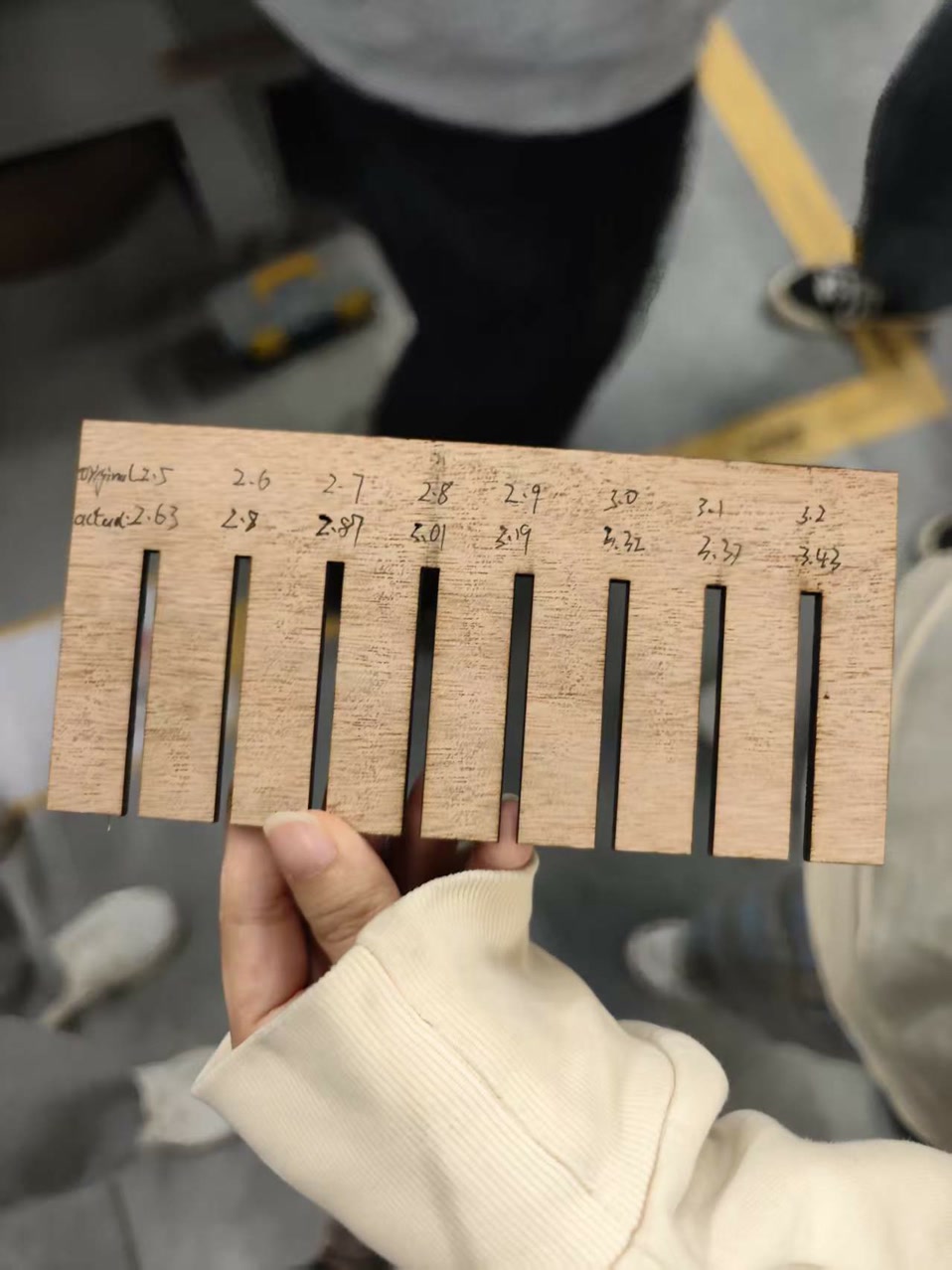
We processed a "Comb" design (a DXF file) featuring slots from 2.4mm to 3.2mm.
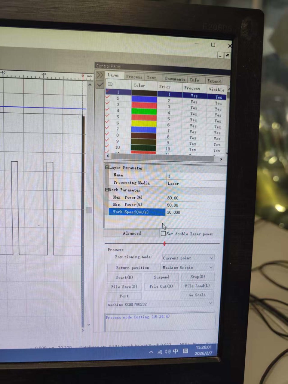
Parameter Strategy for 3mm Basswood: Based on our calibration for 3mm material, we used the following settings:
-
Speed: 30 mm/s
-
Max Power: 80% (For standard cutting paths)
-
Min Power: 50% (Velocity Compensation: Since the machine slows down at the corners of the slots, reducing power prevents over-burning at these vertices).
-
Connection: press port and then connect to make sure the computer and machine are perfectly united.
-
Framing: I clicked "Go Scale" to preview the cutting path, ensuring the laser head moved within the material boundaries and didn't hit any clamps.
-
Start: Finally press start to cut the material.
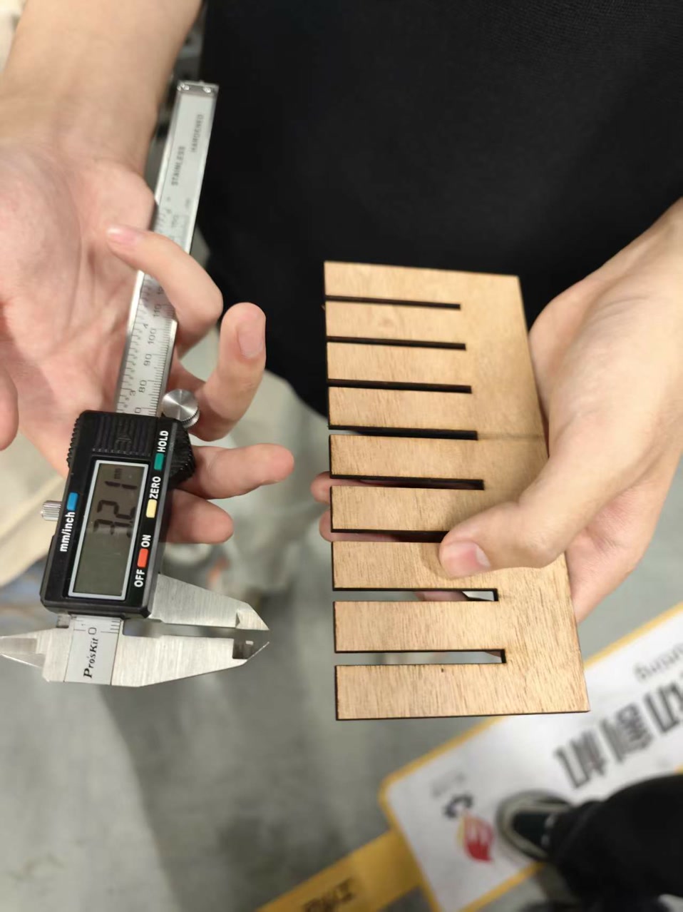
4. Results & Measurement (Data Consistency with Group Test)
To ensure the precision of our group assignment, I followed the exact measurement logic used in our collective test. We focused on finding the "Sweet Spot" where the physical material interacts perfectly with the laser-cut slot.
- Material Calibration: Using a digital caliper, I measured the 3mm Basswood. The actual average thickness was 2.96mm (matching the high-precision measurement standards of our group).
- The Fit Test: We tested the strip against the comb slots.
- Slot 2.80mm: Slightly loose.
- Slot 2.85mm: Too loose.
- Slot 2.74mm (The Winner): This slot provided the perfect Press-fit. The 2.96mm wood snapped into the 2.74mm (designed) slot with a satisfying friction grip.
- Data Recording:
- Measured Material: 2.96 mm
- Designed Slot Width: 2.85 mm
- Measured Slot Width (Post-Cut): 2.96 mm
- Resulting Kerf: 0.11 mm (2.96mm - 2.85mm = 0.11mm).
5. Final Conclusion & Technical Reflections
- The 0.11mm Kerf: Our experiment concluded that the laser removes 0.11mm of material on this specific machine for 3mm Basswood. This means when I design in CAD, I need to account for a 0.055mm offset on each side.
- Why Data Matters: the Kerf directly affects the structural integrity of the project. A difference of even 0.04mm (the difference between 0.11 and 0.15) can mean the difference between a rock-solid joint and one that falls apart.
- Application: For my individual project, I will use this 0.11mm Kerf value. If I want to join two pieces of 2.96mm wood, I will set my slots to 2.85mm (2.96mm - 0.11mm) to achieve a professional-grade press-fit.
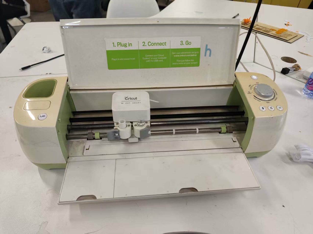
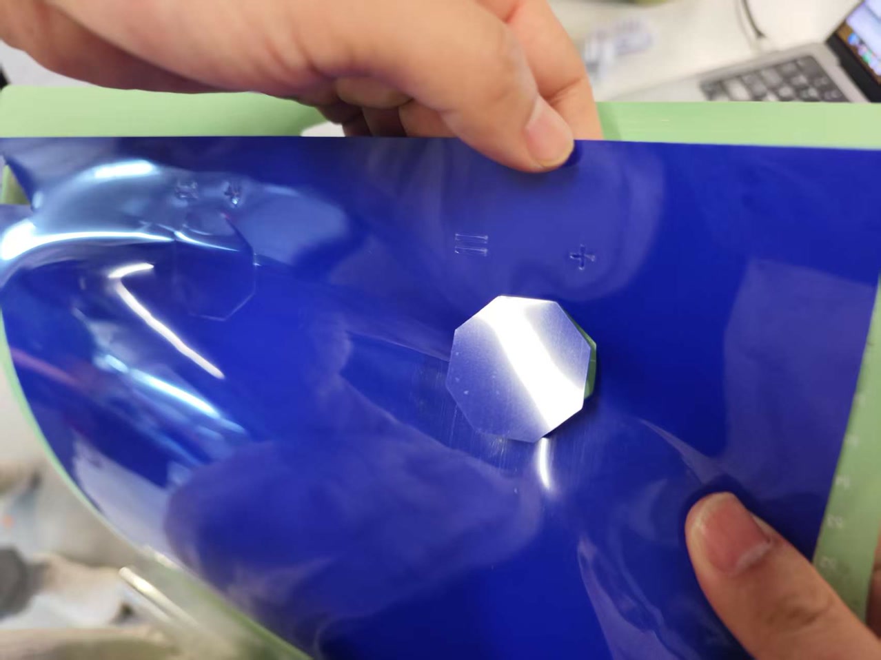
Group Assignment: the Vinyl Cutter process
Besides laser cutting, we also got a hands-on introduction to the Cricut vinyl cutter. It’s essentially a 2D CNC plotter that uses a tiny, sharp blade to follow vector paths instead of using heat or ink.
How it works
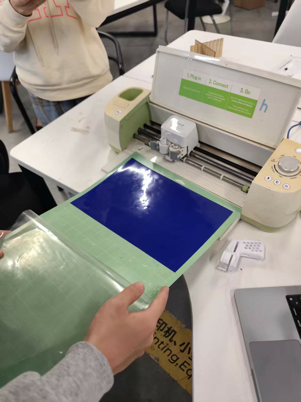
The logic here is purely mechanical. Unlike the laser cutter where we worry about power and frequency, the Cricut focuses on blade pressure and material thickness. Because the blade is physically dragging across the surface, the material must be stuck firmly onto a sticky cutting mat. If it’s not flat, the blade will catch the edges and ruin the design.
Our process and settings
We decided to test it with some colored cardstock.
First, we pressed the paper onto a green StandardGrip mat, making sure there were no air bubbles.
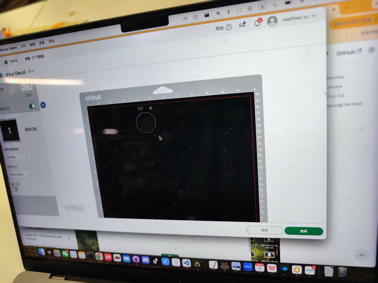
For the software, we used Cricut Design Space. It’s pretty user-friendly: we just imported our shapes and picked "Cardstock" from the material library.
The software is smart enough to know the preset pressure for cardstock, so we didn't have to guess the settings. After aligning the mat in the machine’s guides, we hit the load button and then the flashing start button to let the blade do its work.
Finally we got the cutted piece, with the extremely smooth edge of the shape.
Individual Assignment: Vinyl Cutting - Character Silhouette
1. Introduction
For this week's individual assignment, I designed and cut a vinyl sticker. I chose to create a simplified Mickey Mouse silhouette to practice fundamental 2D CAD skills, including geometric constraints, mirroring, and path cleaning for vector output.
2. Design Process in Onshape
I still used Onshape, a cloud-based parametric CAD software, to ensure the design was precise and scalable.
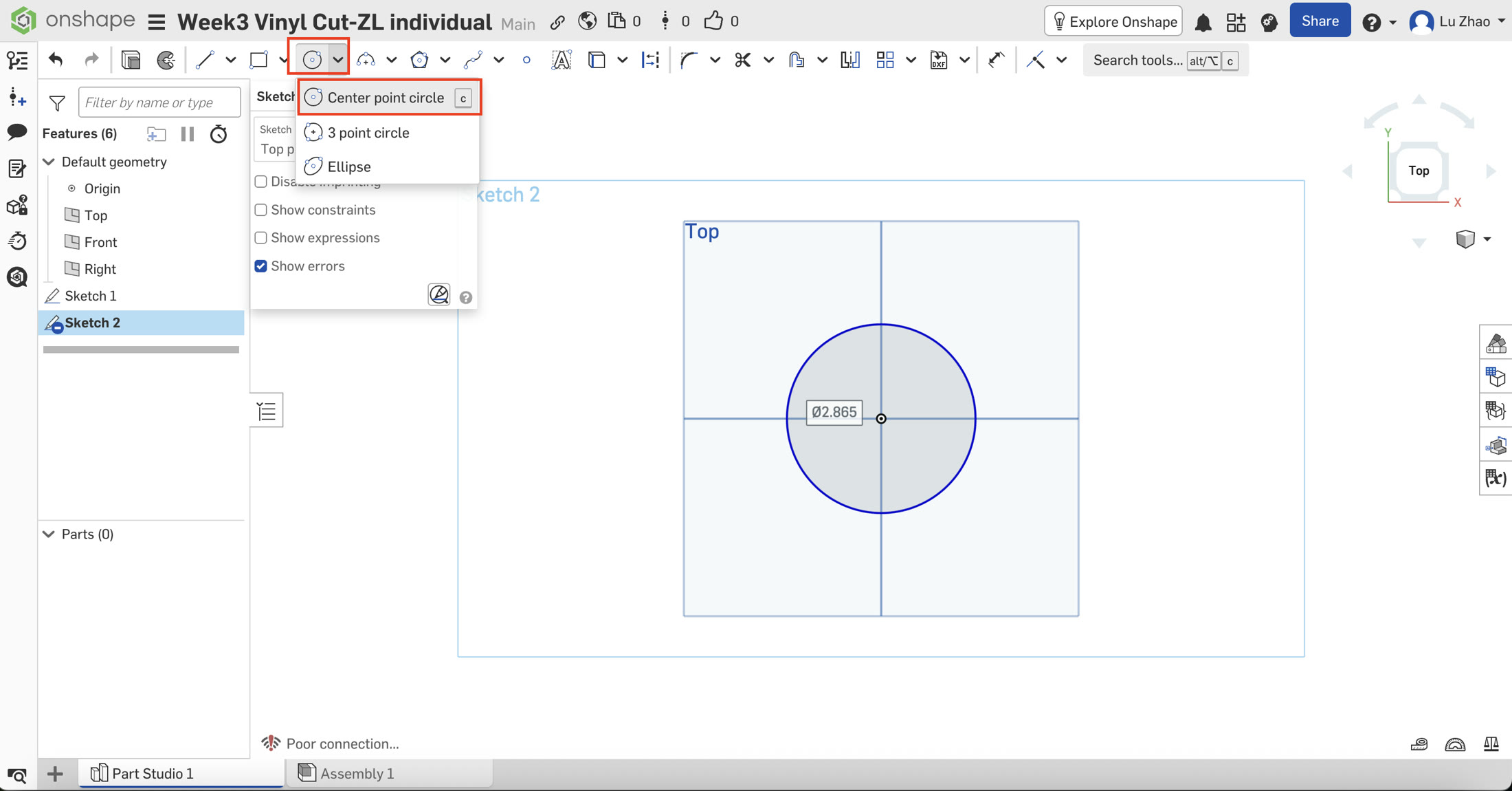
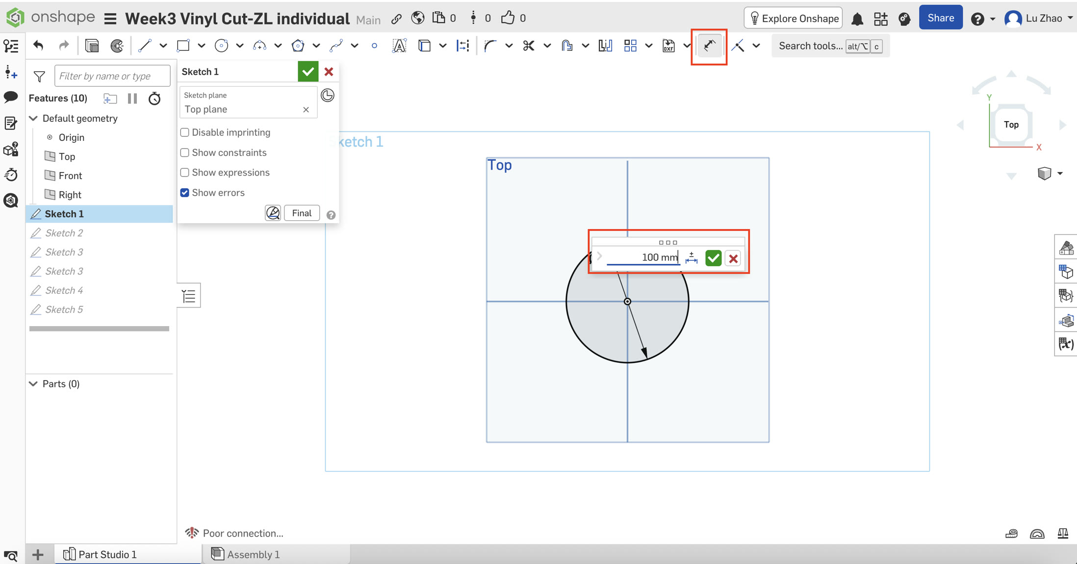
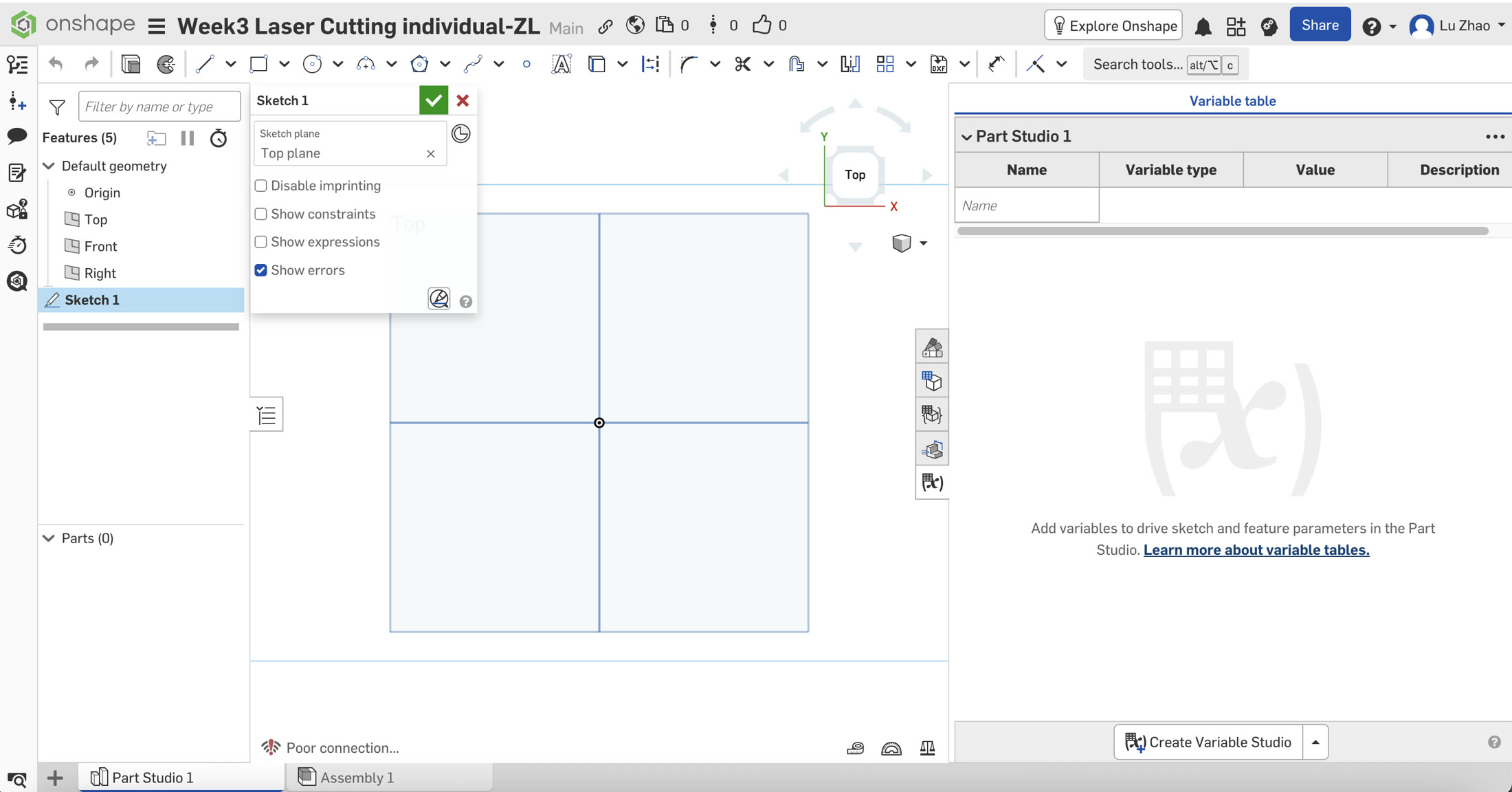
Step 1: Sketching the Base Geometry
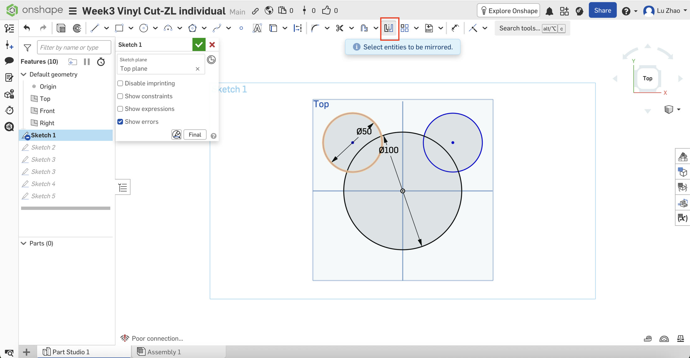
I started by creating a new sketch on the Top Plane. I used the Center Point Circle (C) tool to draw the main head (Diameter: 100mm) centered at the origin.
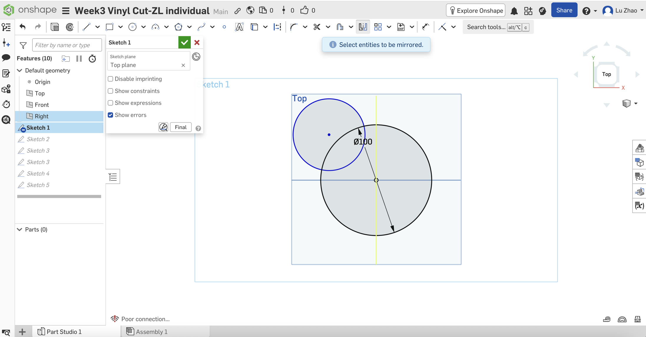
Step 2: Adding the Ears
I drew a smaller circle for the left ear (50mm). To ensure perfect symmetry, a key principle in parametric design, I used the Mirror tool. I selected the middle vertical line as the mirror line and mirrored the left ear to the right side just by clicking the left ear.
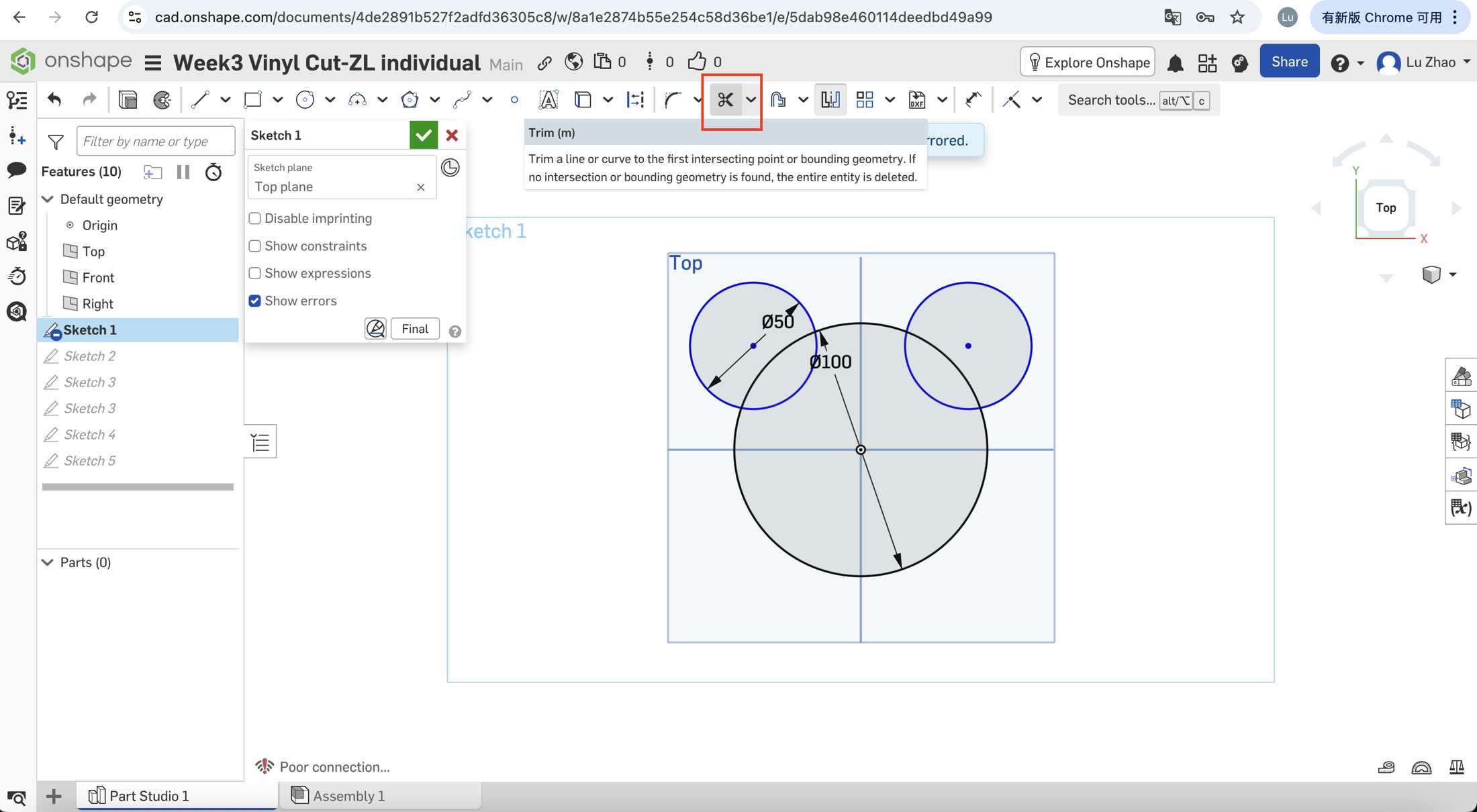
Step 3: Path Cleaning (The Challenge)
To make the file "cut-ready," I needed a single continuous outer boundary without overlapping internal lines.
I initially tried the Trim (M) tool, to remove the extra lines inside the boundary, to make sure the cutter will give me a single shape and not splitted cutted parts.
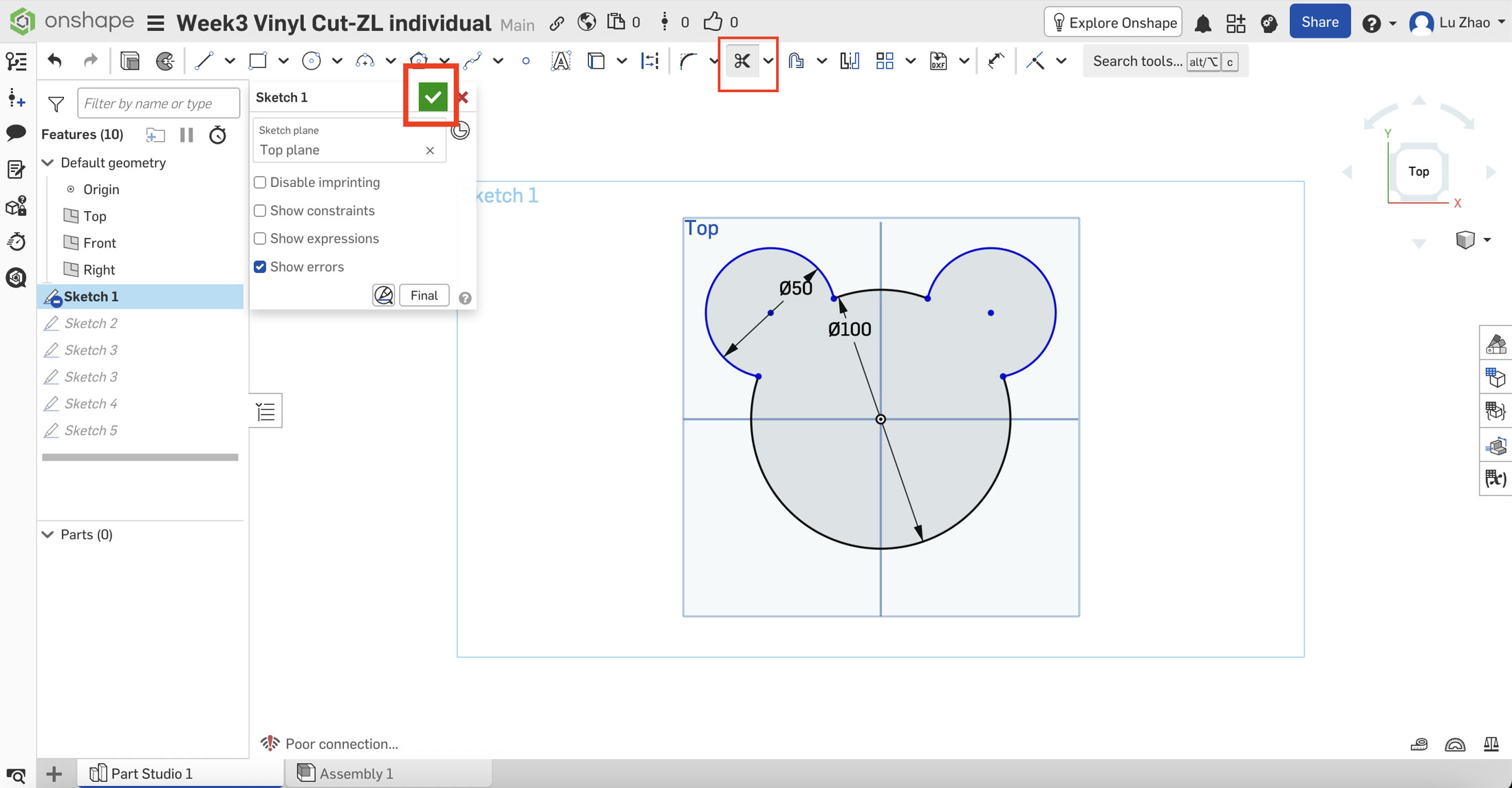
Step 4: Verification
The final shape appeared as a single shaded region in Onshape, confirming the path is fully closed and ready for the vinyl cutter.
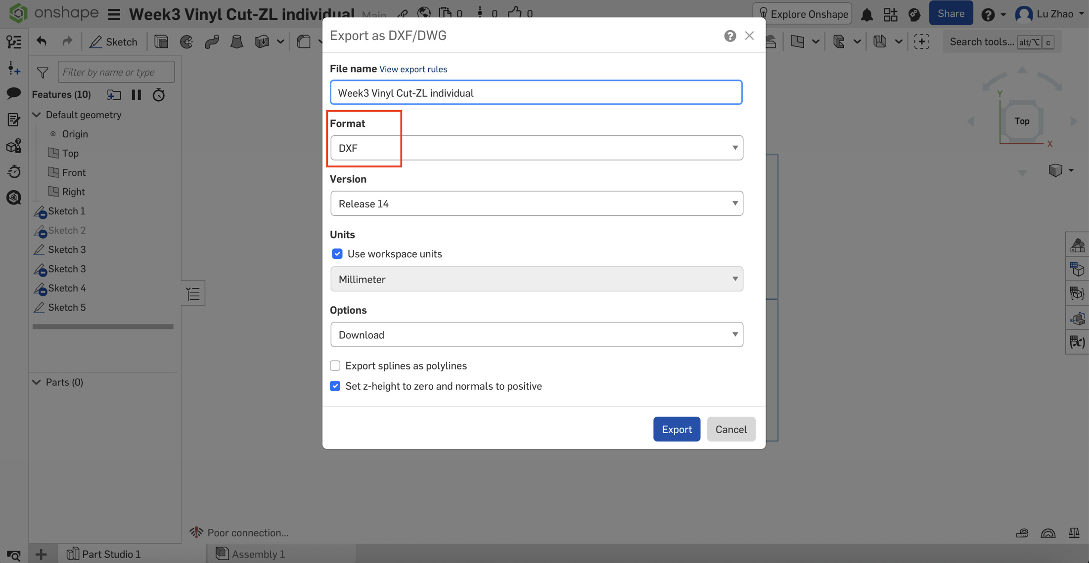
3. Exporting for Production
- Format: I exported the sketch as a DXF file (Release 14). I chose DXF over SVG to maintain absolute scale accuracy when importing into the cutter's software.
- Settings: I ensured all lines were exported as "polylines" to provide a smooth, continuous path for the blade. The DXF file is here: Week 3 vinyl cut DXF
4. Cutting
I used the Cricut Explore for this project. Firstly I downloaded and installed the Cricut Design Space on my own computer and registered.
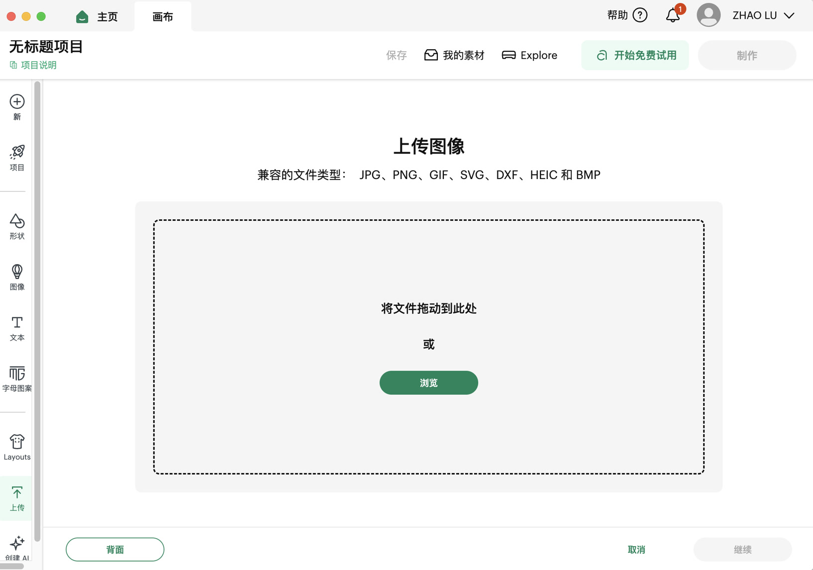
After registering and log-in, click "start new project" and upload my DXF file.
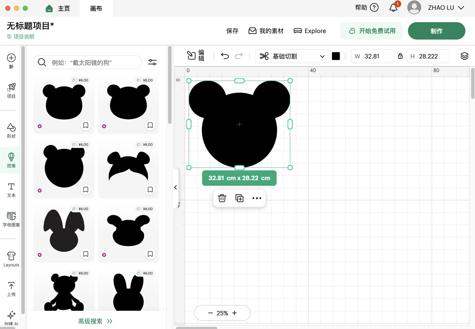
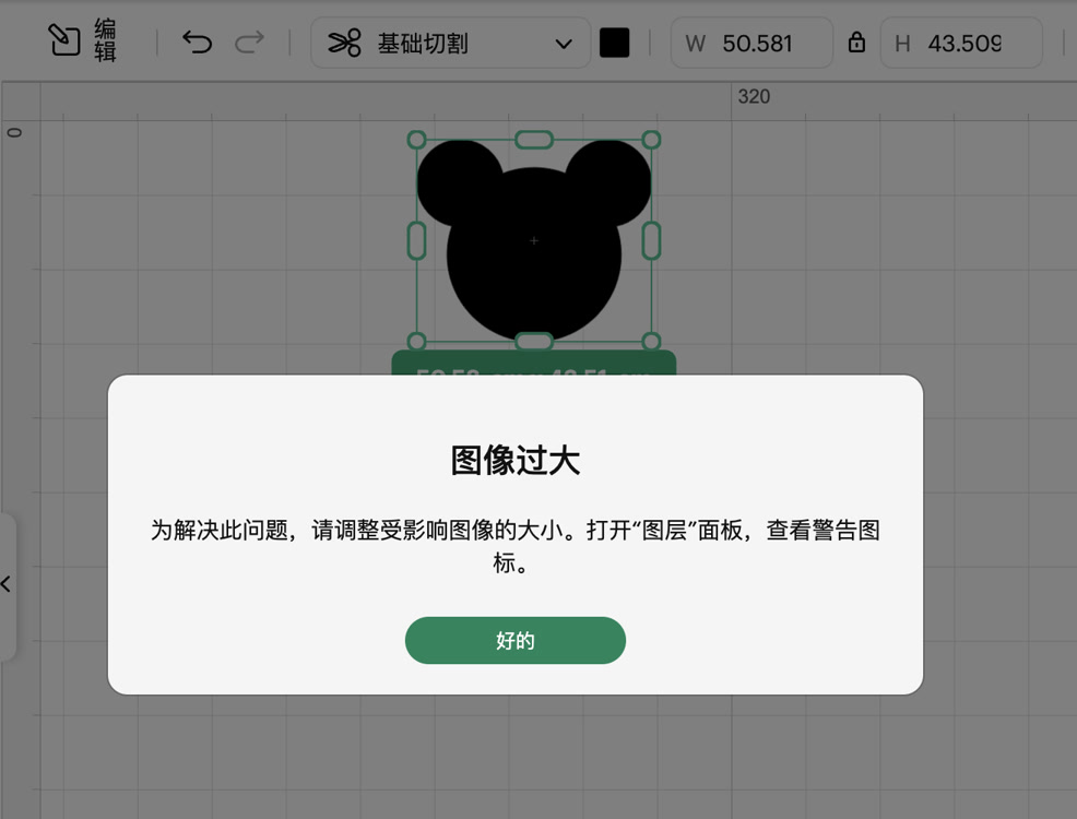
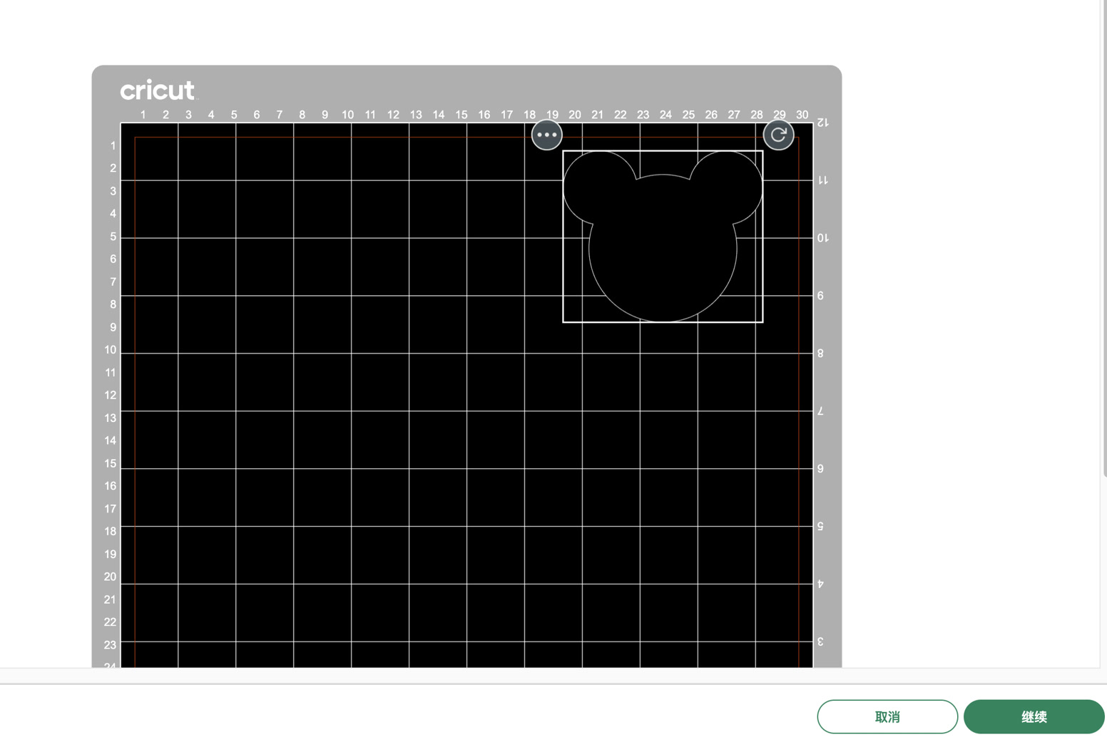
Now I can see the Mickey mouse head on the sheet. However the dimension was originally too big, then I made the size smaller to make it fit for the size and space of the vinyl.
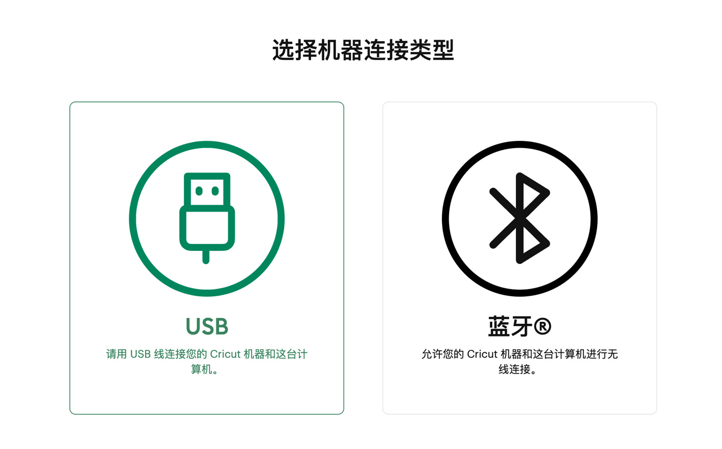
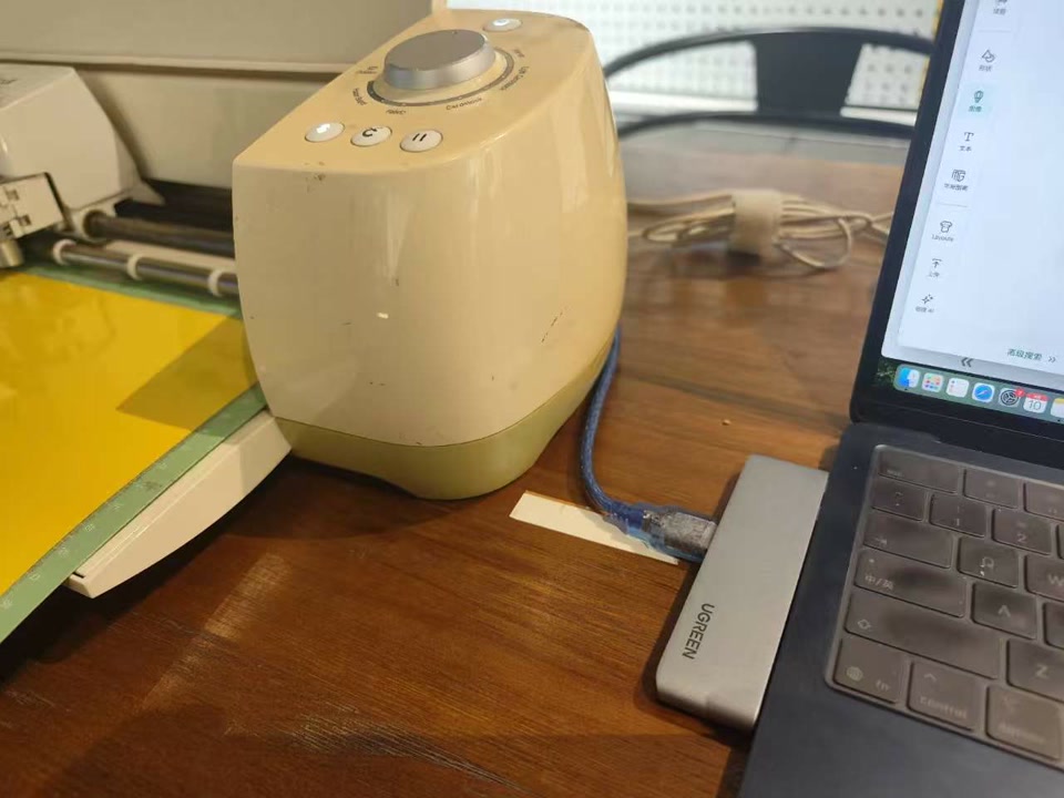
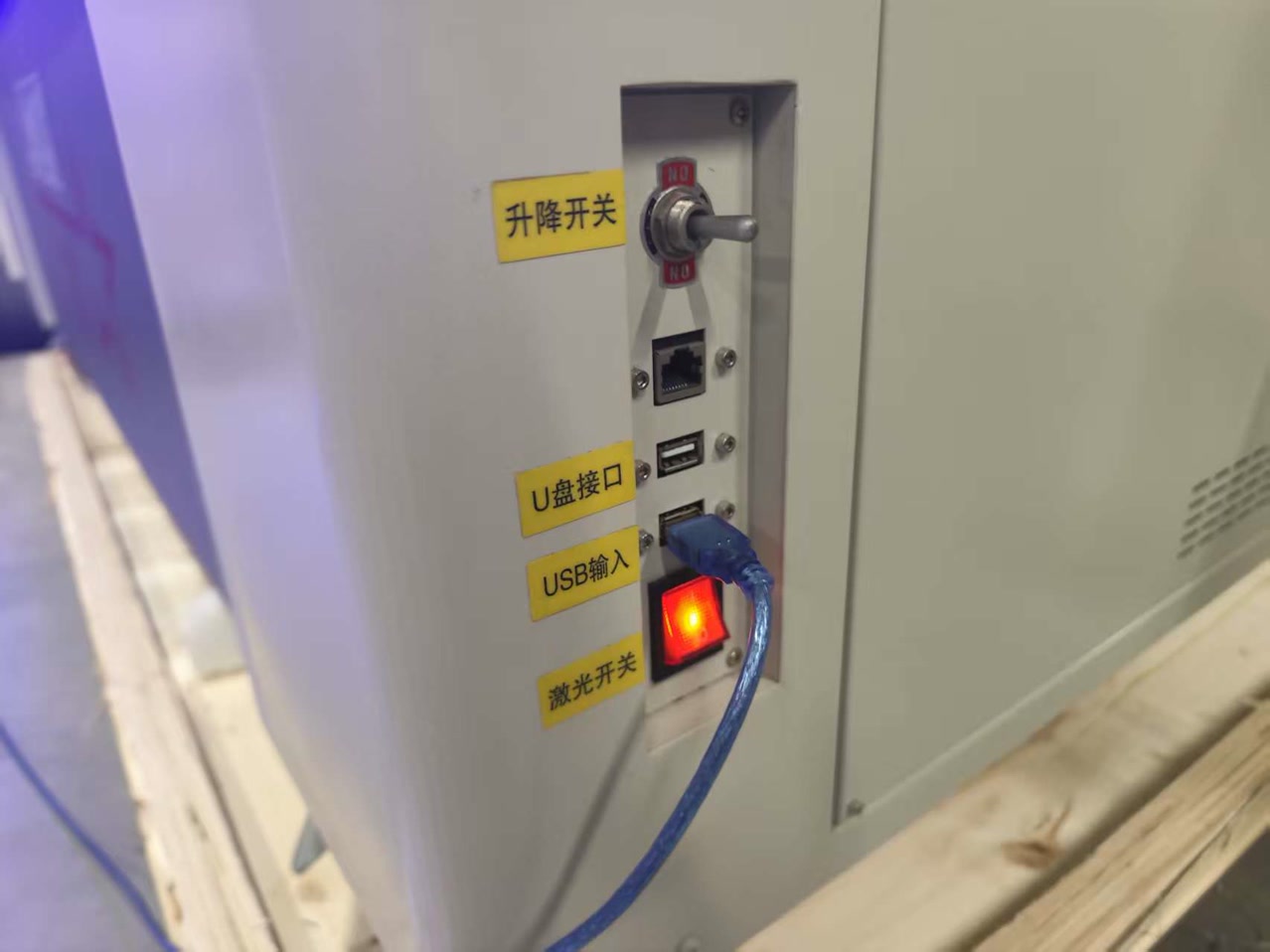
Then I click produce (制作),and it reminds me to connect the computer to the machine and activate the vinyl machine. I chose the USB for connection.
After clicking "NEXT" as the process, I can see the "simulation" of my work on the sheet. I moved it to the clear section for cutting.
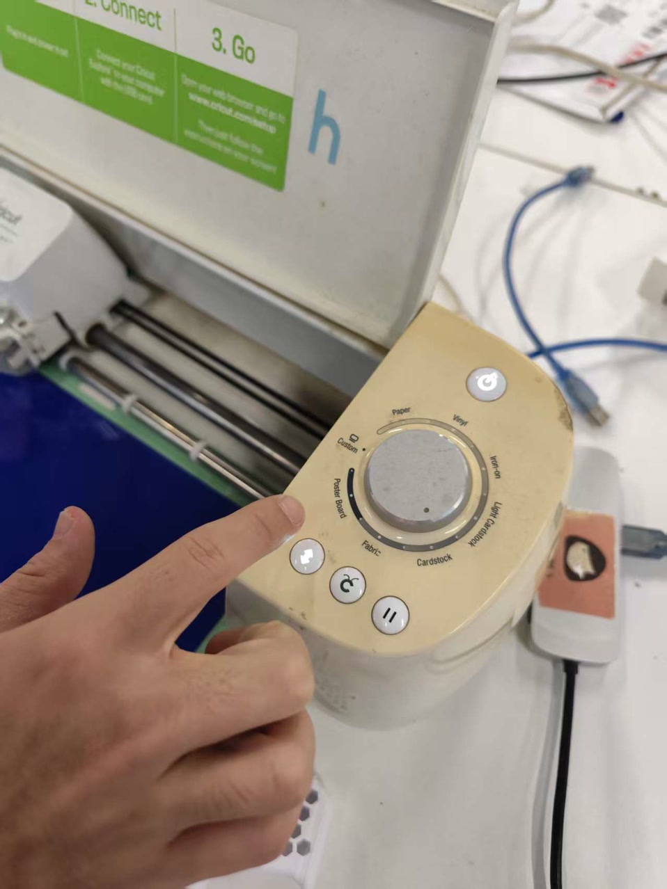
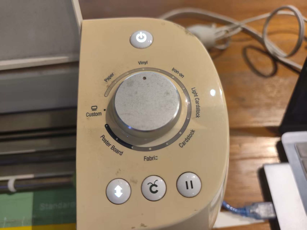
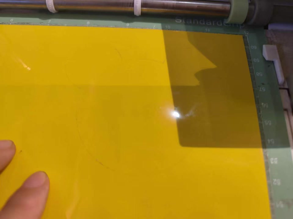
I placed a sheet of yellow vinyl onto the "LightGrip" cutting mat, smoothing it out to avoid any air bubbles that could catch the blade. Then I put it to the right postion to the machine to get prepared to cutting. I set the material as "vinyl", and push the load/unload button which blinked.
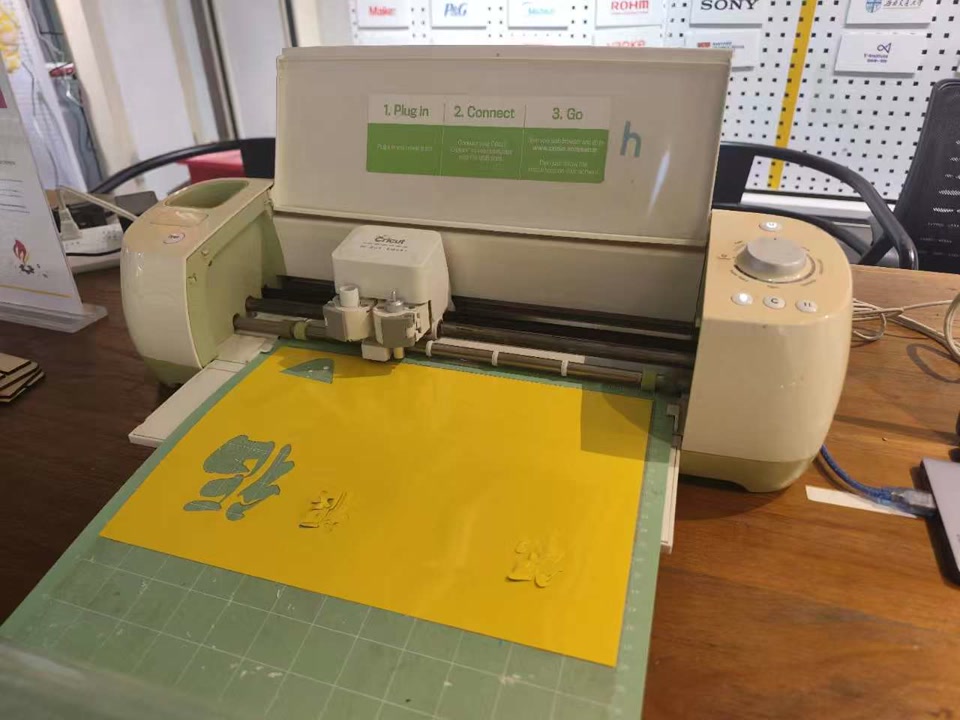
Then the "C" button blinked, I pressed the C button to proceed the cutting. However after this process completed, I encountered a small problem: it is not completely cutted, I cannot remove my cutted part from the vinyl.
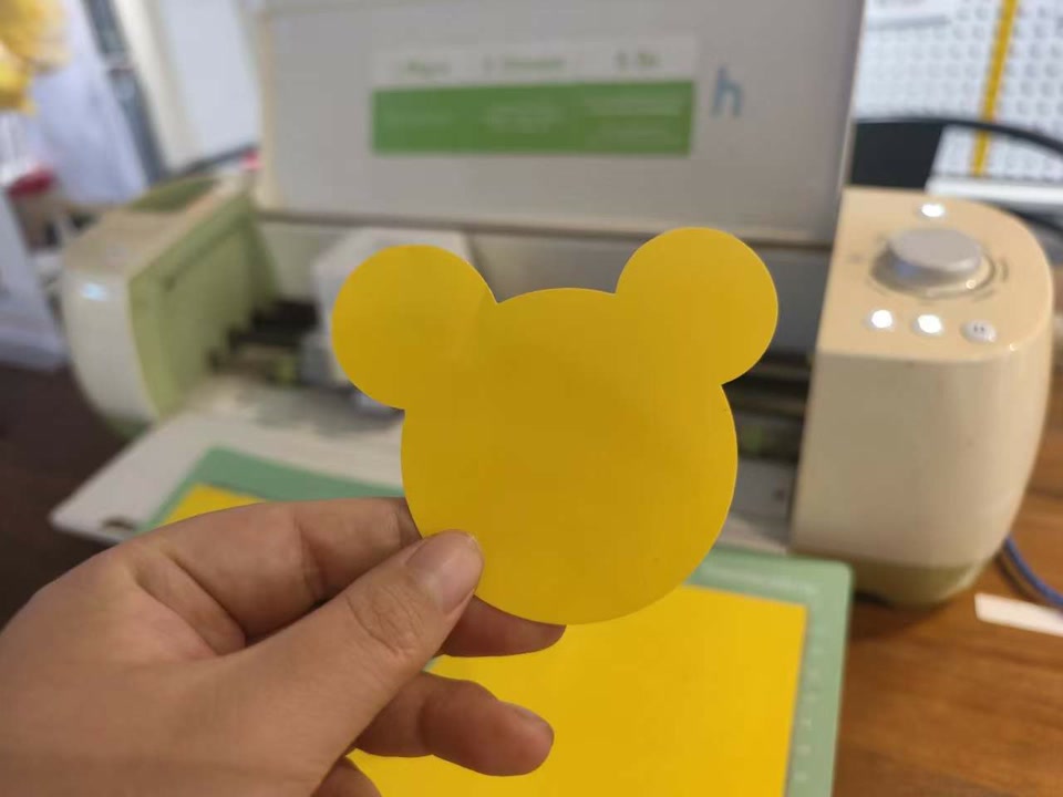
I checked and found the thickness of this vinyl might be bigger then standard, the blade of machine has to go deeper, then I tried to change the mode from vinyl to poster board, and tried the cutting process again. Finally I got my Mickey mouse head.
Individual Assignment: Laser Cutting
1. Assignment Overview
For my individual assignment I focused on creating a parametric press-fit kit—a set of components designed to interlock securely without the need for adhesives, accounting for material thickness and laser kerf.
2. Characterizing the Machine (Group Work Context)
Before designing, I needed to understand the "Kerf" (the amount of material the laser removes).
- Measured Kerf: 0.11 mm (based on previous calibration tests on the machine).
- Material: 3.0mm Basswood (though actual measurements varied).
3. Parametric Design in Onshape
I chose Onshape for this assignment because of its robust parametric capabilities. Instead of drawing static shapes, I used variables to drive the entire design.
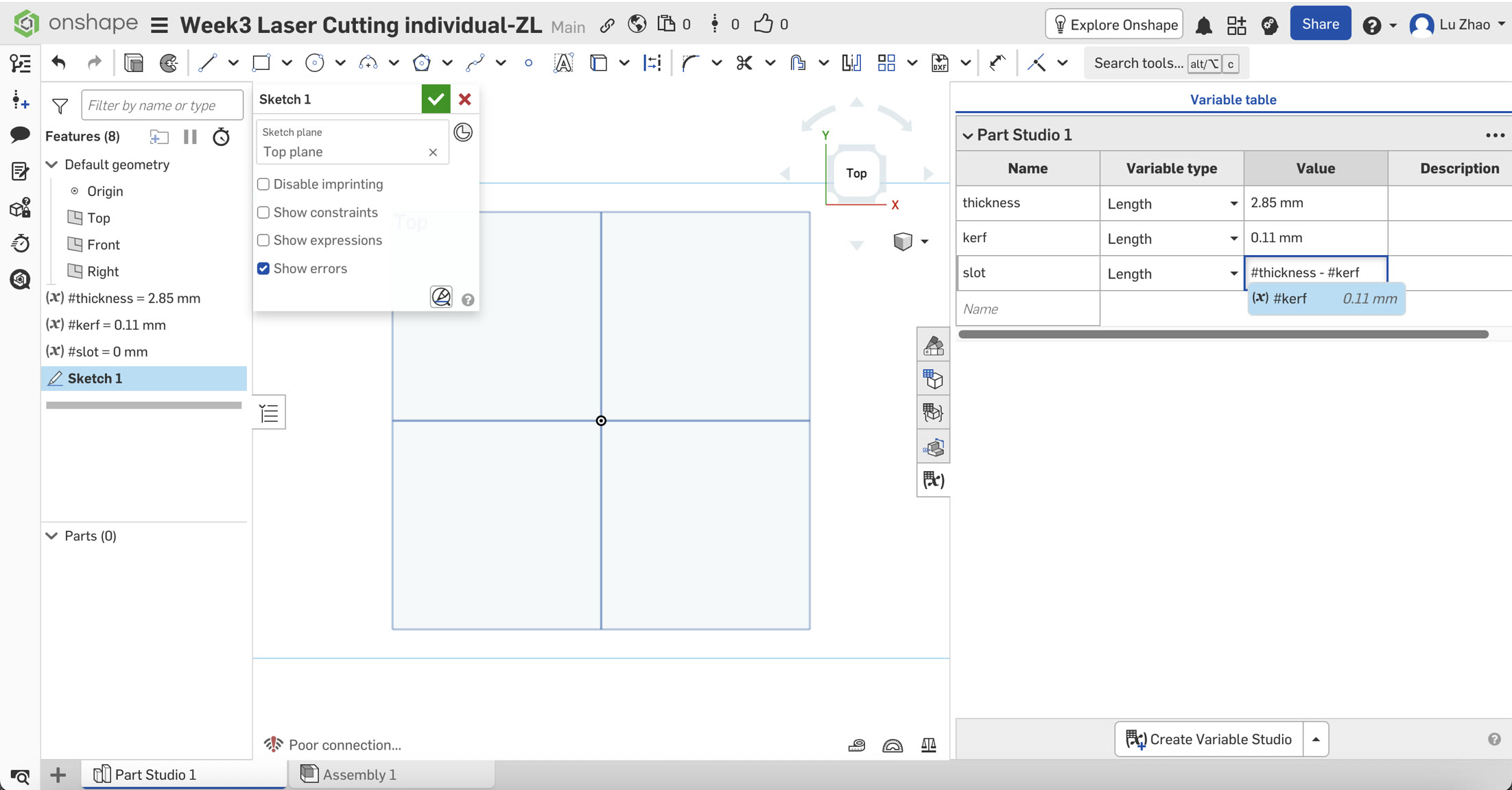
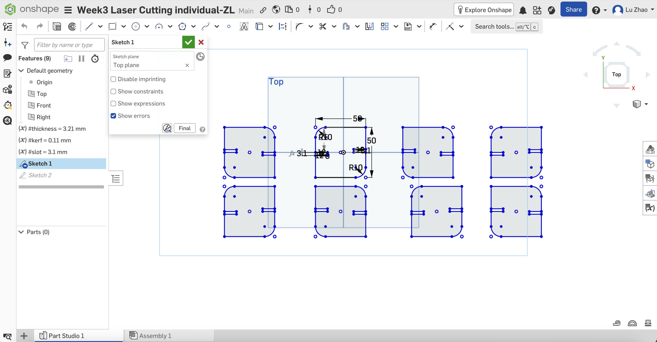
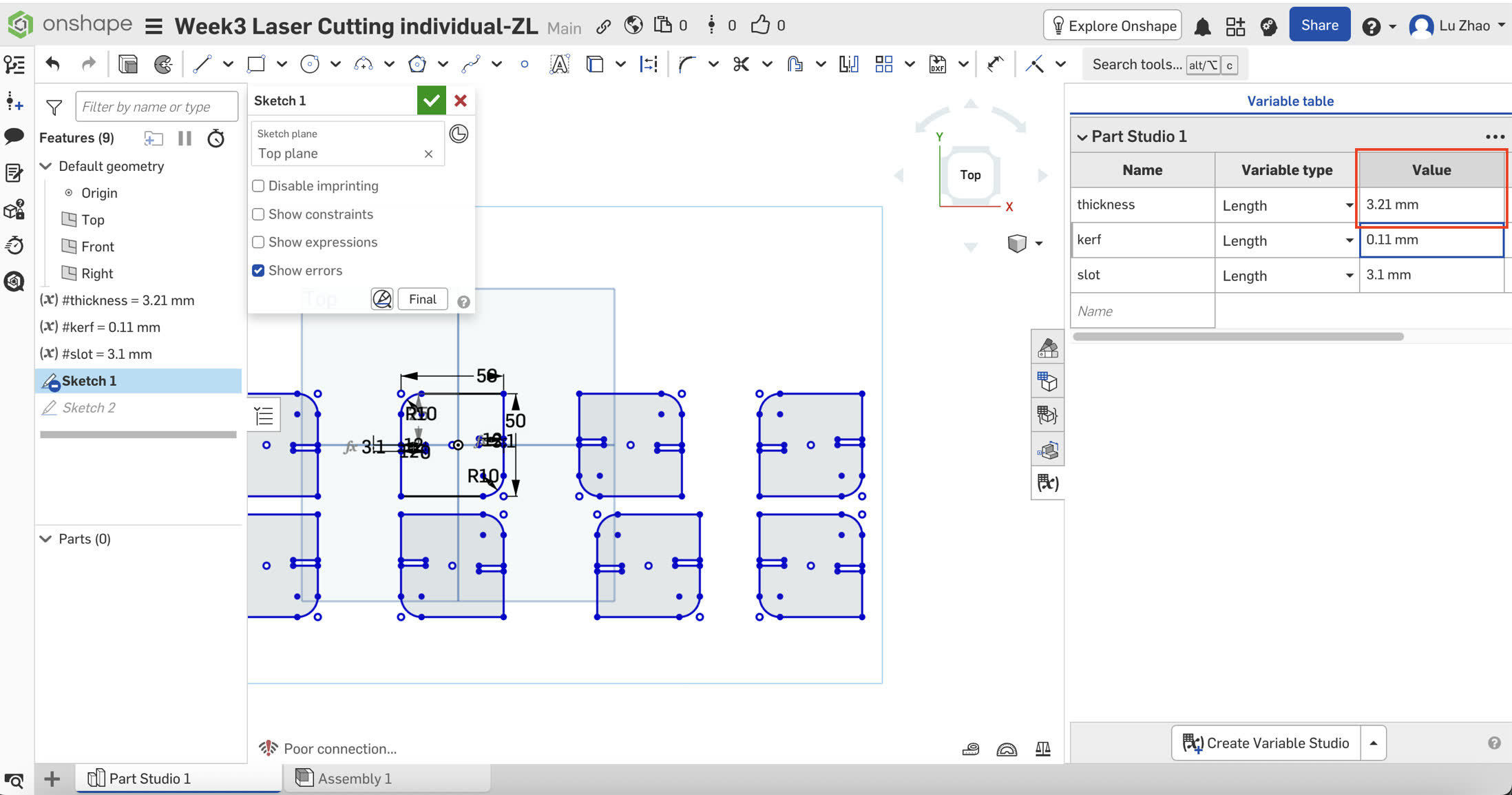
A. Setting the Variables
I established a variable table to ensure the design could adapt to any material thickness:
- #thickness: Initially set at 2.85mm, but updated to 3.21mm after a final caliper measurement of the actual basswood sheet.
- #kerf: Set to 0.11mm.
- #slot: Defined by the formula #thickness - #kerf. For my final cut, this resulted in a slot width of 3.10mm.
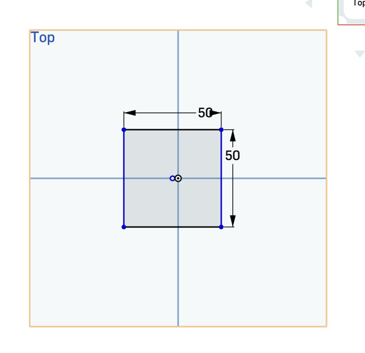
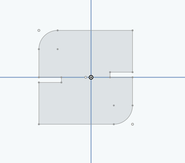
B. Sketching and Constraints
I clicked the centre point rectangle and designed a 50mm x 50mm square first.
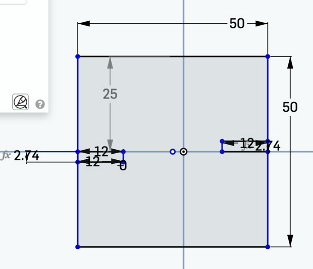
I used the corner rectangle to draw the slot, starting from the middle point of one side of square.
For dimension of the slot, I set the depth to 12mm and the width to my #slot variable. I just put the #slot in the dimension of the slot width, thus it will be same as in the variable table automatically. Since originally I set the thickness of 2.85mm and kerf of 0.11mm, the slot width became 2.85-0.11=2.74mm.
I manually draw the second slot on the diagonal opposite side to ensure complete control over the geometry, maintaining a depth of 12mm.
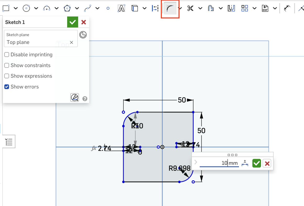
I applied a 10mm Radius Fillet to the corners using the "Sketch Fillet" tool to give the pieces a professional finish and better tactile feel.
C. Final Path Cleaning
Before duplicating the parts, I used the Trim (M) tool to remove the overlapping lines where the slots met the square’s edge. This ensures the laser follows a single, continuous closed loop.
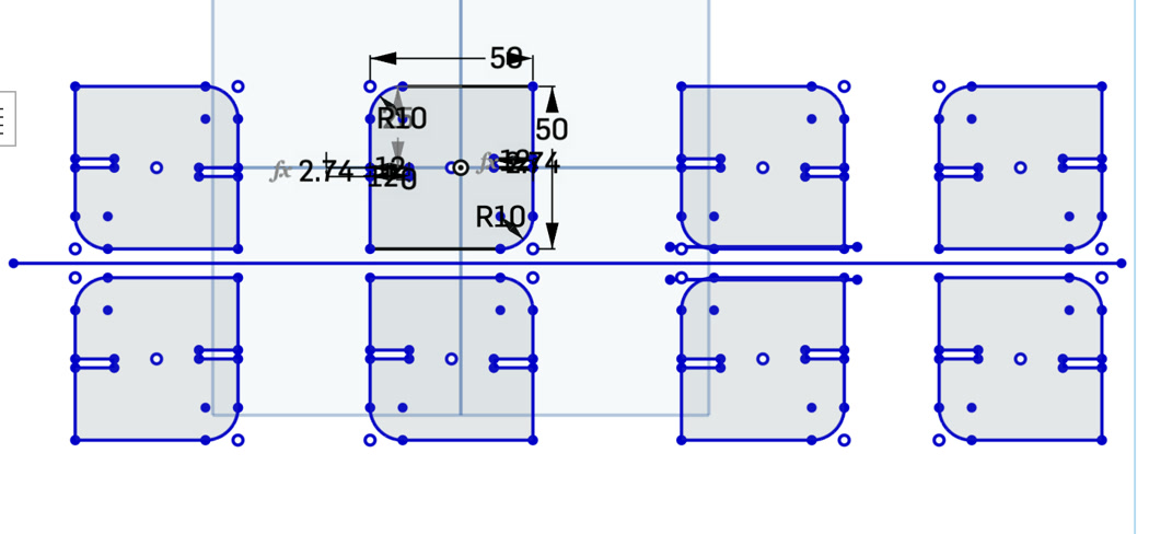
4. Preparing for Production ( quantity from 1 to 8)
To produce the 8 pieces I need for the kit, I used the Mirror Tool.
I drew a construction line to serve as a central axis. I mirrored the original part to create a pair.
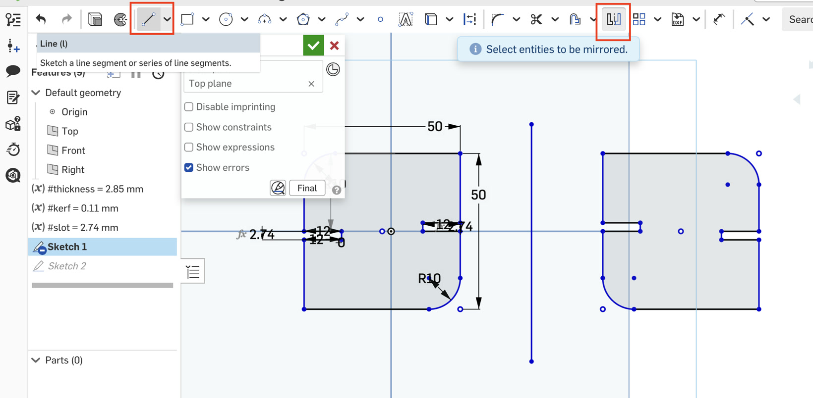
I repeated the process until I had a layout of 8 identical parts ready for export.
Then I remove the central axis lines because I don't need to cut them.
5. Laser Cutting & Assembly
Exporting to DXF
I exported the Part Studio as a DXF (Release 14) with "Splines as Polylines" enabled to ensure compatibility with the laser software. The DXF file is here: Week 3 laser cutting DXF
The process
The most critical moment was the final measurement. Just before cutting, I re-measured the basswood and found it was 3.21mm. Because of my parametric setup, I simply changed the #thickness variable to 3.21, and all 8 parts updated instantly.
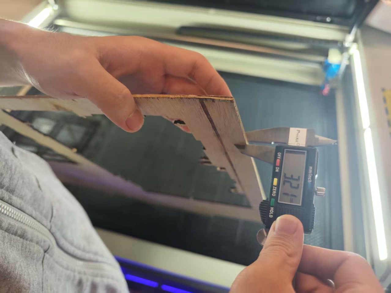
The parts were cut on the SMDX (深明大鑫) Industrial CO2 Laser Cutter.
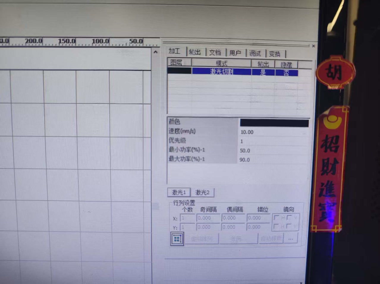
I imported the DXF file to the computer software RDWorks; and started to adjust the settings for the next cutting procedure.
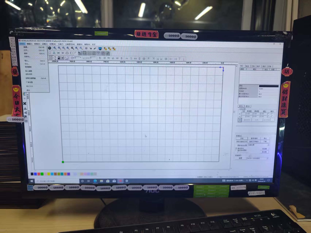
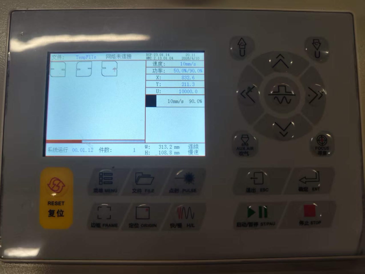
Firstly I set the max power of 90%, min power of 50%, speed of 10mm/s to make sure the board can be cutted to the bottom completely.
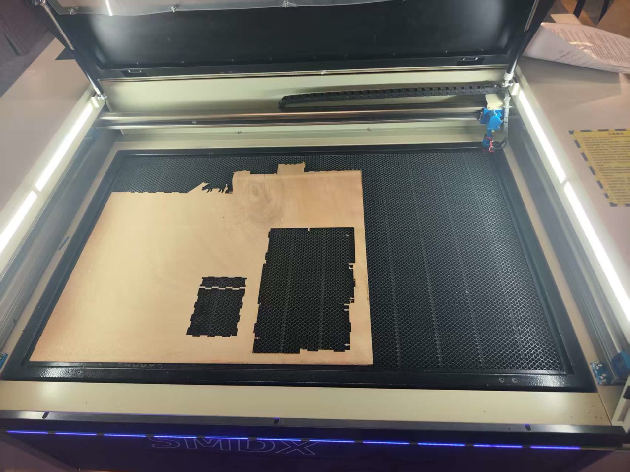
Before cutting, I put the 3.21mm thickness of basewood board to the working place in the laser cutting machine, set the original position of the laser cutting head, and then run "Go Scale" from the computer.
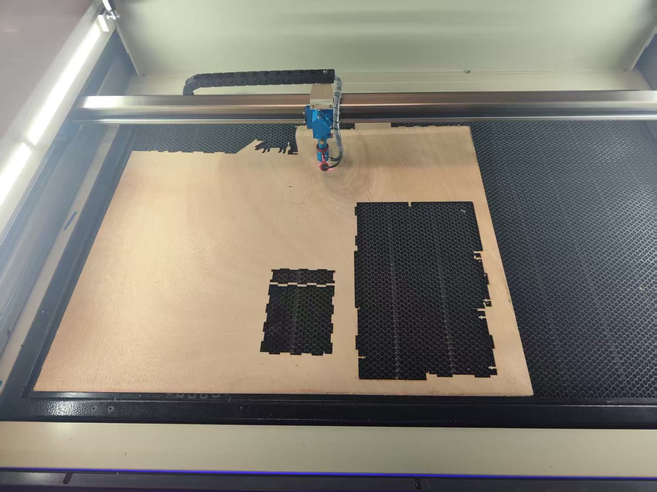
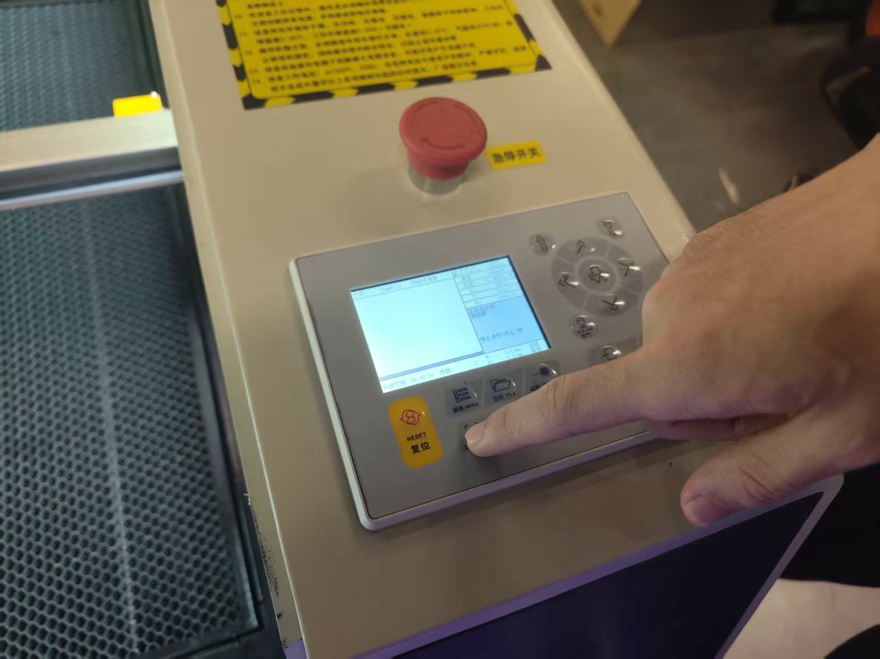
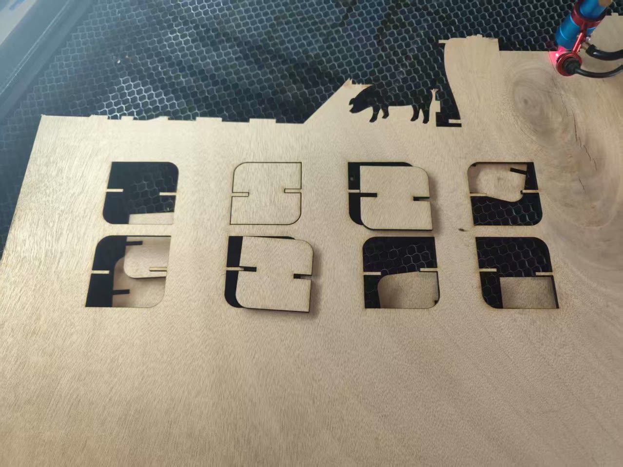
After everything is set-up, I clicked "Start" on computer to cut my parts. It is interesting that I can see the process of the cutting process from the screen of the machine.
After the cutting process, I found nothing happened to the board, I tried to figure it out and found I did not turn on the laser switch of machine! Then I turned it on, and run this cutting process again.
Finally, after the cutting process completed, I have my cutted 8 units.
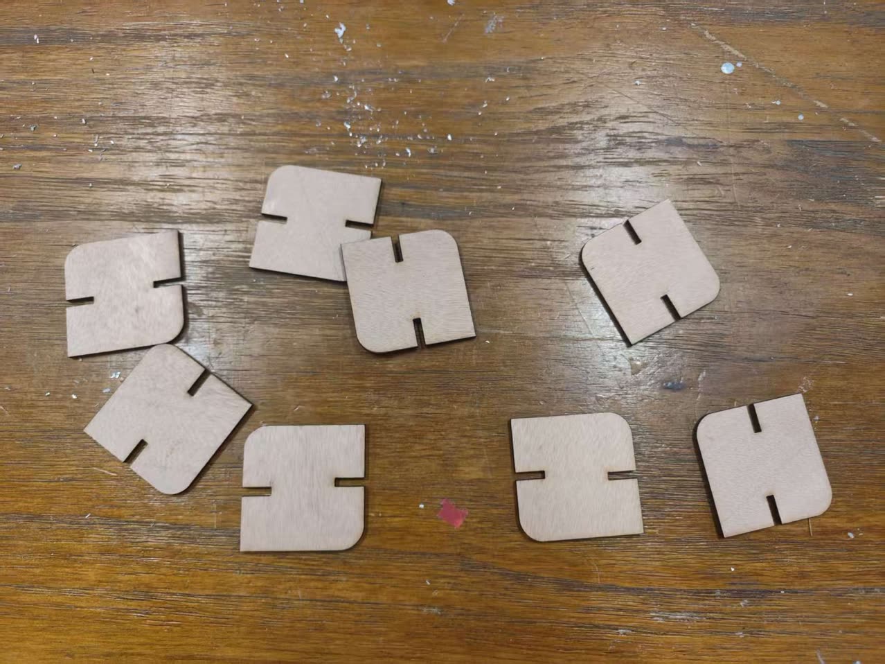
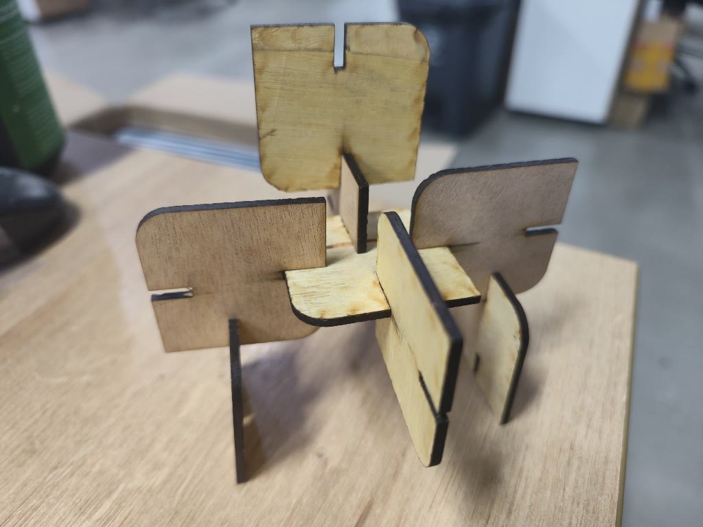
I tried to assemble them together, hoping it is not too loose or too tight. Thanks to the 0.11mm kerf compensation, the pieces achieved a perfect friction fit (Press-fit). They "clicked" together securely without the need for glue, yet could be disassembled to create different structures.
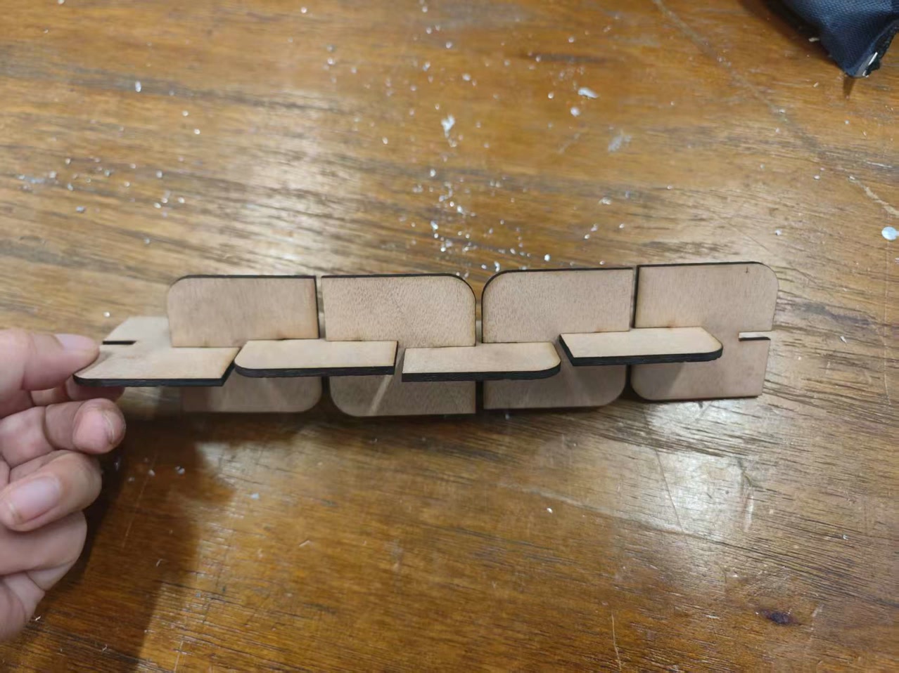
The components connected smoothly and securely. The slot friction was well balanced—firm enough to keep the structure stable without adhesive, while still allowing the pieces to be taken apart without difficulty.