Week16 - System Integration
This week's efforts were directed toward the system integration phase of the final project. I systematically sorted out all the required electronic modules and subsequently integrated the structural parts that fully encloses the electronic system. The architectural overview of my project "Smart Morin Khuur: The Glowing Melody" is illustrated as follows.

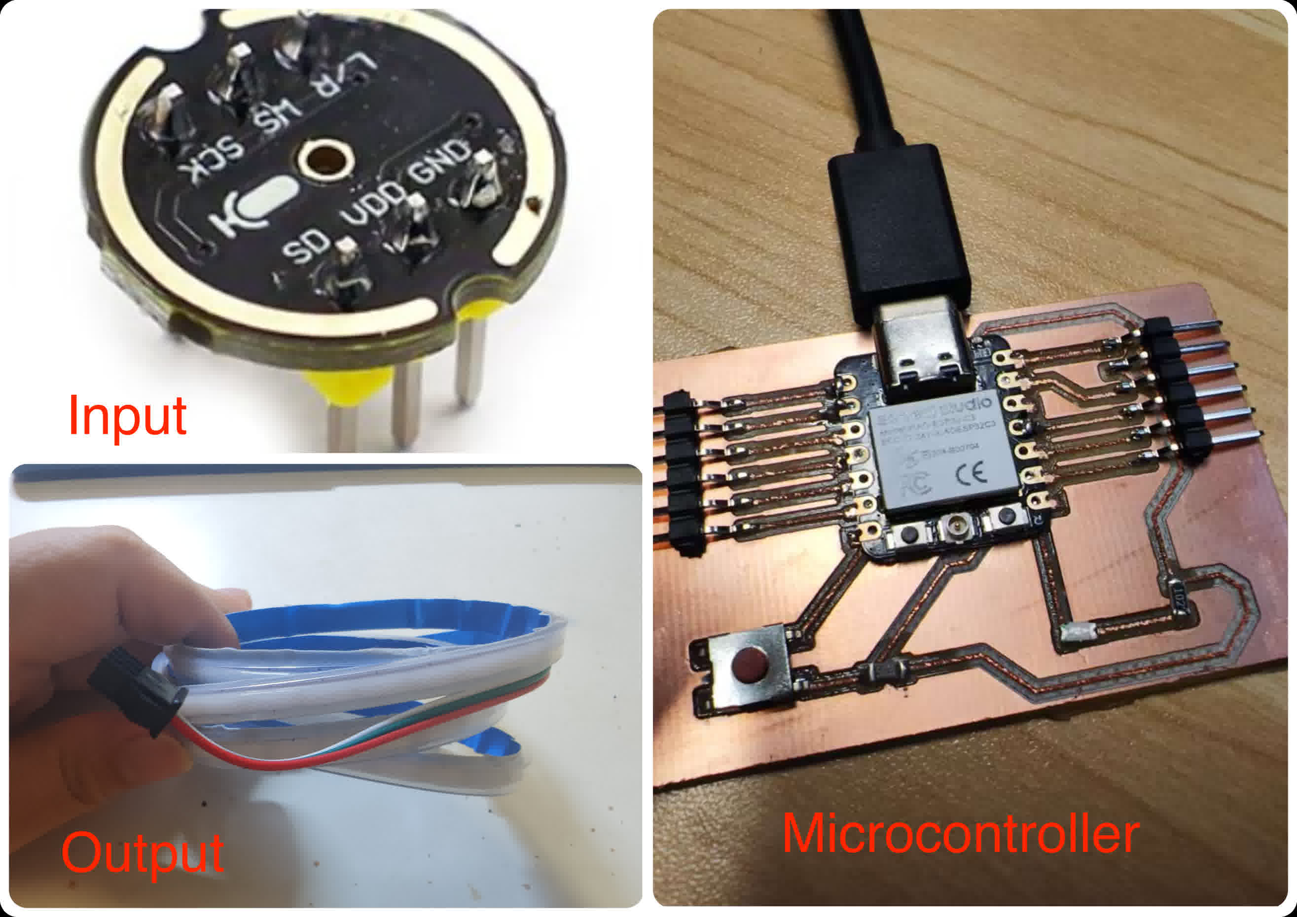
System Integration - Electronics
To transform the traditional Morin Khuur into a digital, sound-reactive instrument, I designed an embedded electronics system centered around the Seeed Studio XIAO ESP32C3. This microcontroller was chosen for its ultra-compact form factor, built-in Wi-Fi/Bluetooth, and powerful I2S audio processing capabilities. The interactive visual feedback is driven by a high-density 5V COB WS2812B LED Strip, which eliminates light spots for a smooth neon effect. For audio input, I integrated an INMP441 I2S Omnidirectional Digital Microphone to capture real-time acoustic data from the instrument's soundbox. Power is supplied by a 5V 2000mAh Li-Po Battery mounted on the removable back panel for easy access.
Main hardware composition:
-
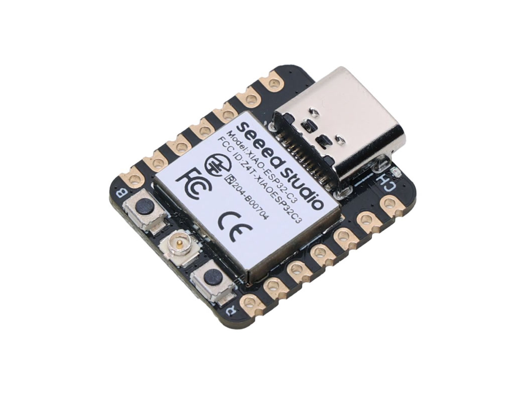
Microcontroller: XIAO ESP32C3
-
Input: INMP441 Omnidirectional MEMS Microphone Module with I2S Interface
-
Output: 5V WS2812B COB RGB LED Strip - 8mm Wide, IP65 Waterproof, 160 LEDs/m
BOM (Bill of Materials) List:
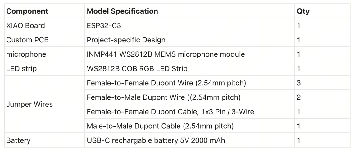
Microcontroller: XIAO ESP32-C3
Custom PCB:
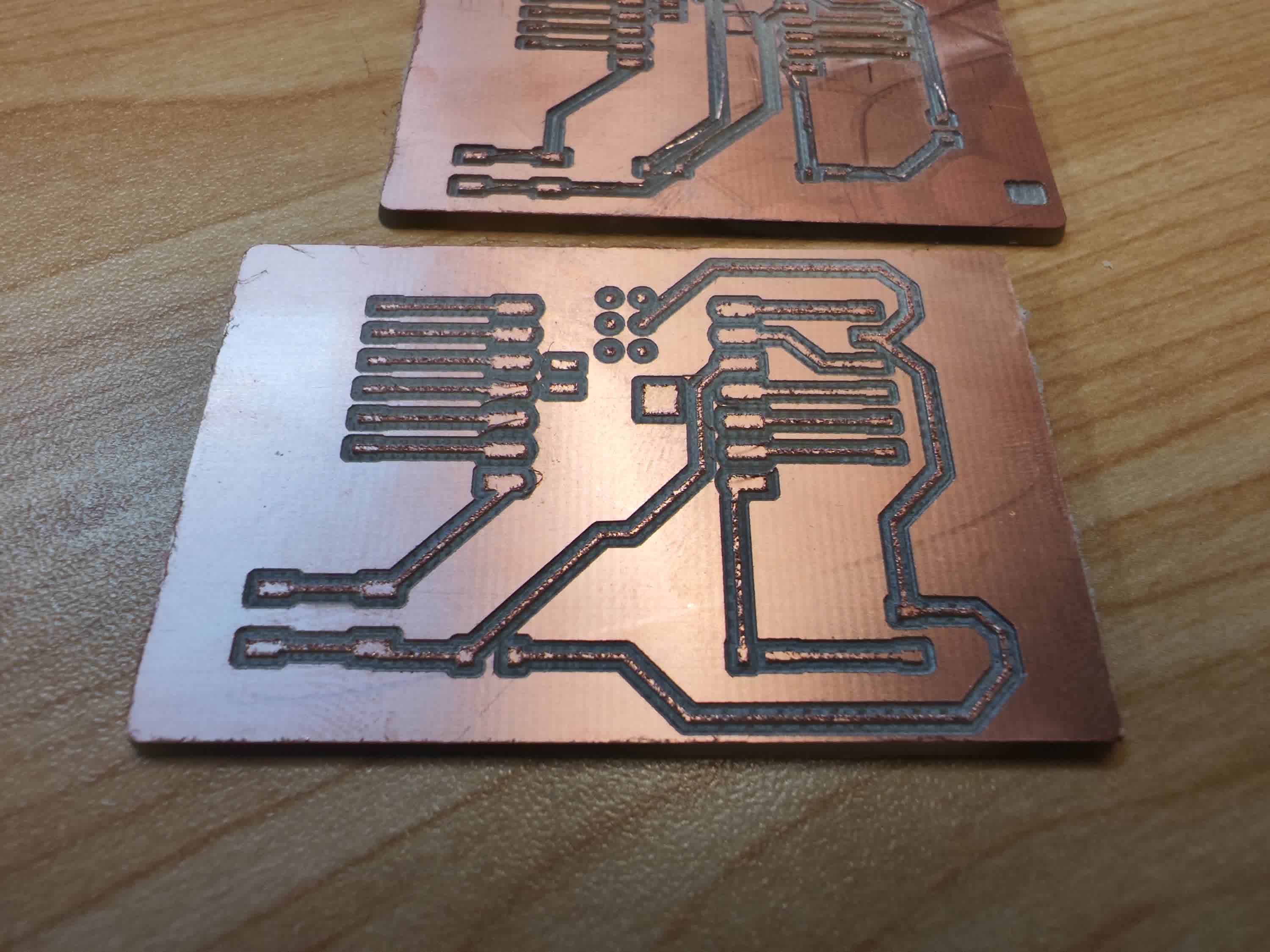
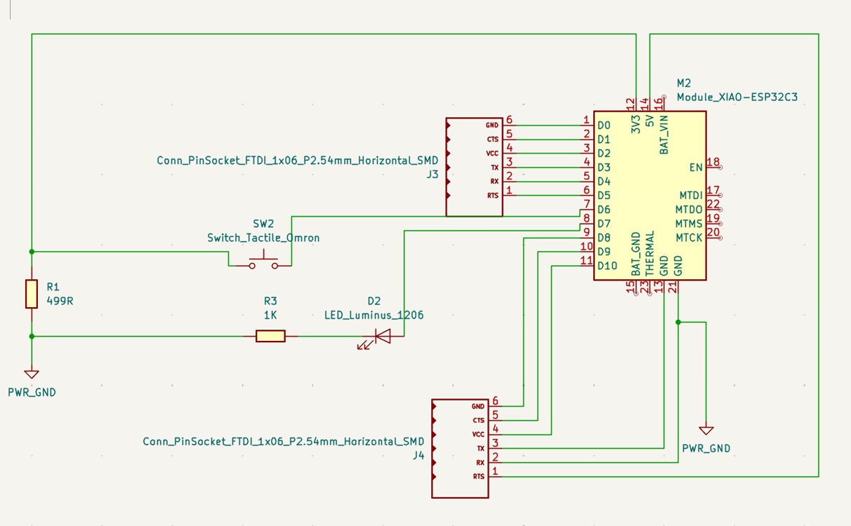
Circuit Schematic Design & PCB Diagram:
Refer to Week6 - Electronics Design | Lu Zhao | Fab Academy 2026 for more details.
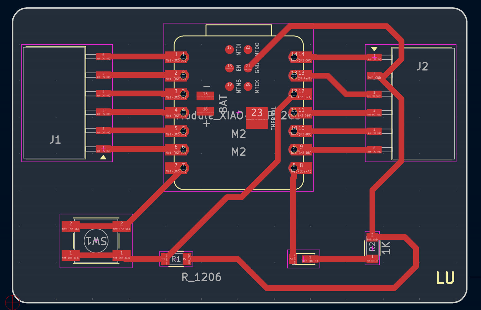
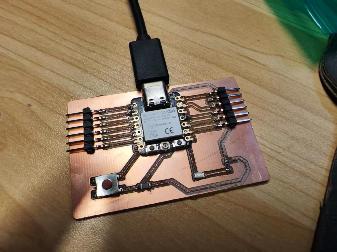
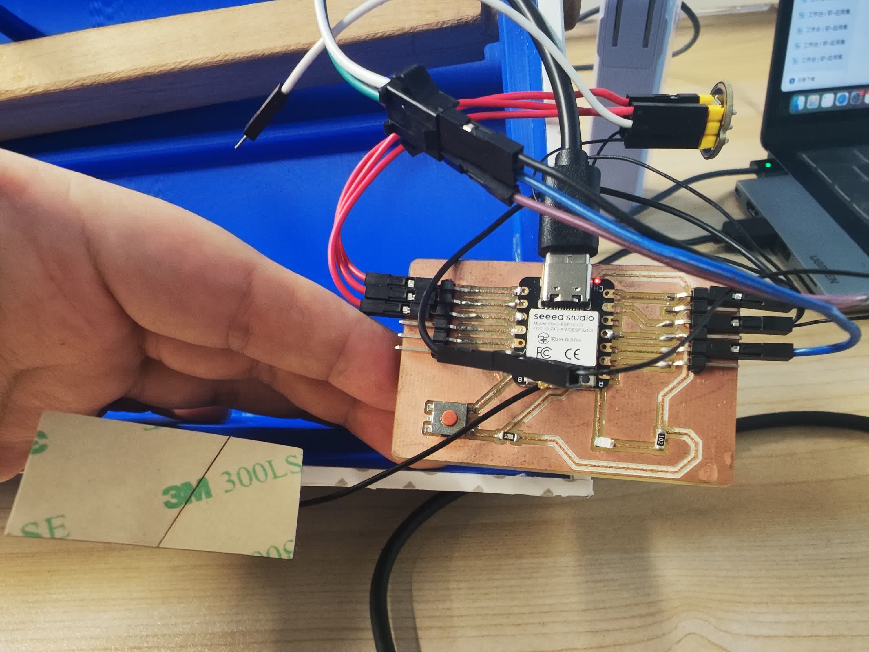
Integration of XIAO ESP32-C3 with custom PCB:
for production of custom PCB, refer to Week8 - Electronics Production | Lu Zhao | Fab Academy 2026
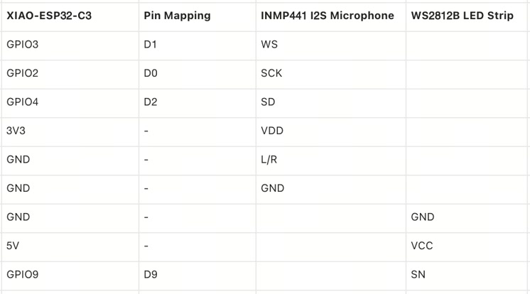
Circuit Connection, Pin Mapping
The wiring was carefully planned to utilize the pin matrix capabilities of the ESP32-C3 chip while strictly adhering to voltage safety limits.
For the lighting system, the LED strip's data line was connected directly to the D9 (GPIO 9) pin. The LED strip is a 5V component and it connects to XIAO 5V.
For the INMP441 I2S Microphone, precise routing and strict voltage control were critical. I mapped the connections as follows:
-
VDD to 3V3: This is an absolutely critical safety measure. The microphone operates strictly on a 1.8V - 3.3V logic level.
-
GND to GND: Standard power ground.
-
L/R to GND: Channel selection. Tying this pin to the ground configures the microphone to output data exclusively on the "Left Channel".
-
SCK to D0 (GPIO 2): Serial Clock (BCLK) for the I2S interface.
-
WS to D1 (GPIO 3): Word Select (LRCLK) to dictate the data channel timing.
-
SD to D2 (GPIO 4): Serial Data (DIN) output carrying the captured audio signal to the microcontroller.
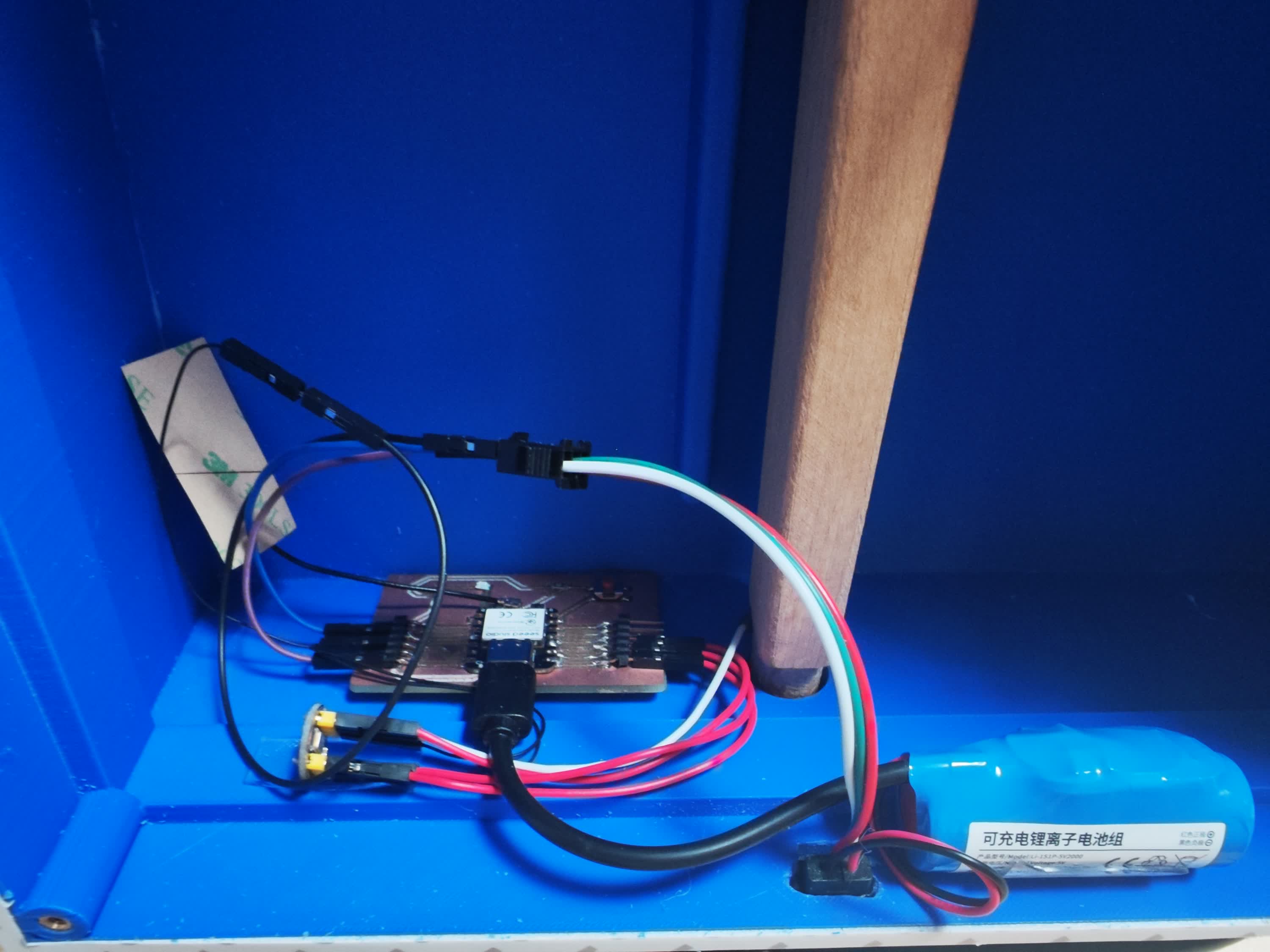
Main components for circuit
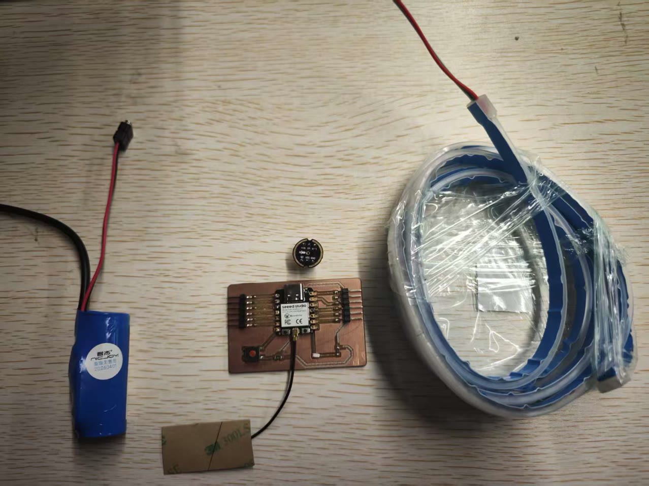
I used the dupont cables to connect all electronic parts together.
System Integration - Structure
The Assembly Challenges
Assembling the 3D-printed acoustic resonance box was honestly the most nerve-wracking phase of this entire project. At this stage, the individual parts were printed and the electronics were prepped, but physical integration meant facing several critical "make-or-break" checkpoints. If any of these failed, the instrument would either be physically impossible to put together or acoustically ruined.
Before making any permanent moves, the questions of major engineering and acoustic concerns ran through my head:
Structural Tension: I planned to permanently fuse the front panel to the middle frame using AB epoxy. But would this chemical bond actually hold? Once the tailpiece and strings were installed, the mechanical tension pulling on that joint would be massive. I was genuinely worried the panel might warp or suddenly rip off under the stress.
The Sound Post Calibration: Was my calculated length for the 3D-printed sound post perfectly accurate? If it was even slightly too short, it wouldn't stand tightly between the front and back panels to transfer vibrations. If it was too long, I wouldn't be able to screw the back panel shut.
Neck Alignment & Tolerances: Did I get the dimensions and positions exactly right for the top square slot and the bottom round hole on the middle frame? If the wooden neck didn't slide in properly, the structural core of the instrument would fail immediately.
I/O Clearances: Was the exit hole I designed actually large enough, and in the correct location, to smoothly route both the WS2812 LED strip and the internal battery's Type-C charging port to the outside?
Screw Matching: Would the screw pillars I modeled on the middle frame perfectly align with the holes on the back panel? Furthermore, would the M3 brass heat-set inserts melt perfectly into those pillars, or would they misalign and ruin the plastic?
Acoustic Sealing: Because I designed the back panel to be removable (using only six M3 screws instead of glue), I was terrified of air gaps. Any leak would destroy the internal air pressure and cause an awful buzzing sound. I had to trust that the 1mm thick 3M foam tape I prepared would perfectly seal the chamber.
The Final Tone: Above all else, despite carefully considering the acoustic principles, the 3D printing filament, and the infill settings, my ultimate fear was the actual sound quality. I didn't want a project that just looked cool but sounded like a hollow plastic toy. I desperately wanted it to sing with the rich, beautiful voice of a real Morin Khuur.
With these seven major concerns hanging over the process, I took a deep breath and began the physical assembly.
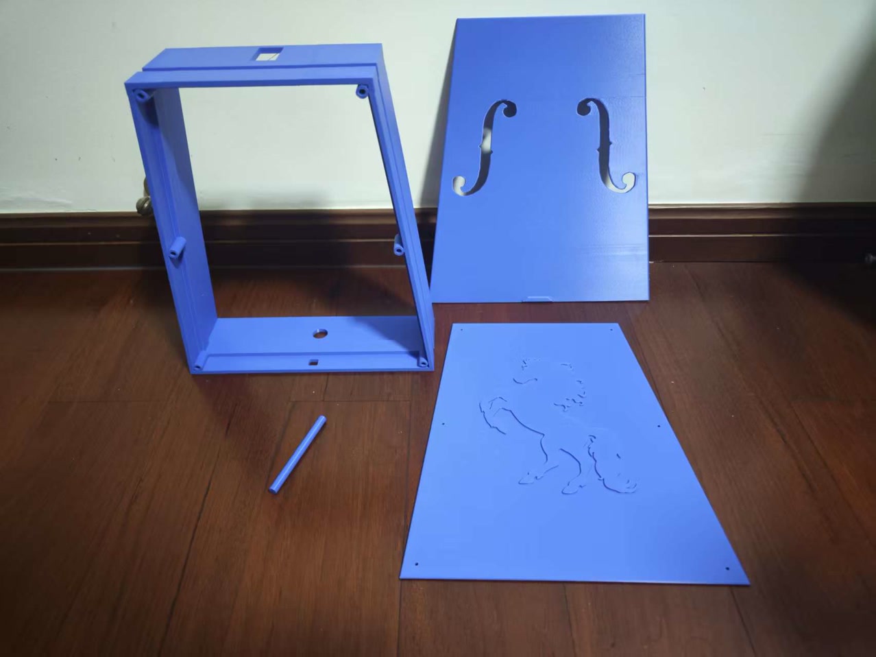
Step 1: The "Tub" Construction (Day 1)
To handle the heavy string tension, I used heavy-duty AB epoxy to permanently fuse the front panel to the middle frame.
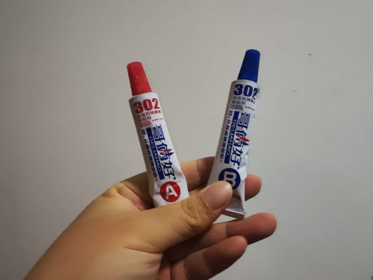
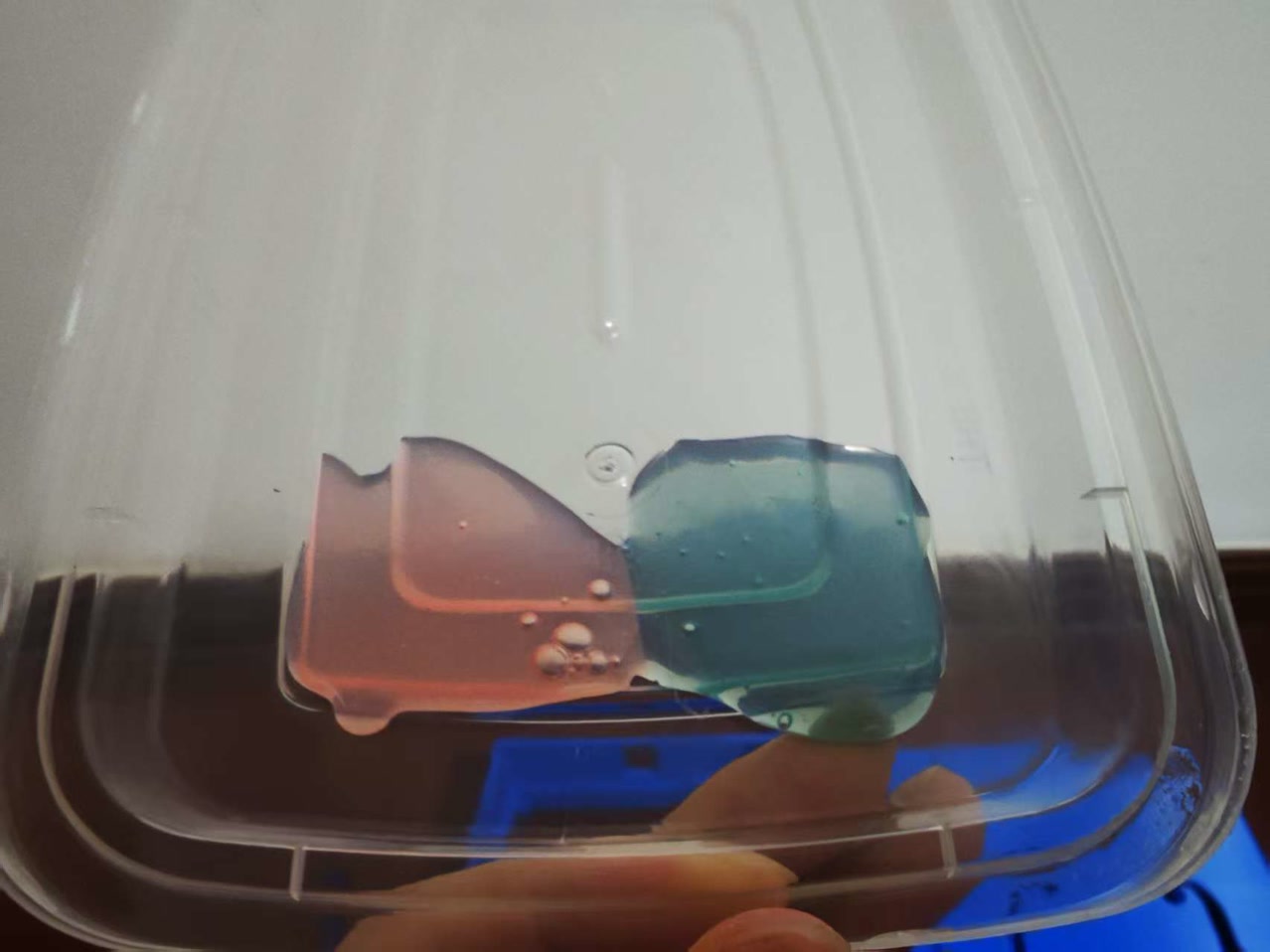
I spent time manually pressing the seams together to squeeze out any trapped air, ensuring a perfectly airtight seal. I carefully aligned the front panel to maintain its designed symmetrical overhang. Since AB epoxy reaches its maximum strength after 24 hours, I left this assembly to cure overnight.
Step 2: Neck Verification & Sound Post
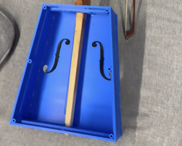
The next day, before doing anything else, I did a dry fit of the wooden neck into the top square slot and bottom round slot of the middle frame. It fit perfectly!
With the neck removed, I installed the 3D-printed sound post using a drop of 401 superglue. The sound post is the acoustic "soul" of the instrument—it structurally bridges the front and back panels, transferring the string vibrations from the front board to the entire body to generate that deep, resonant bass.
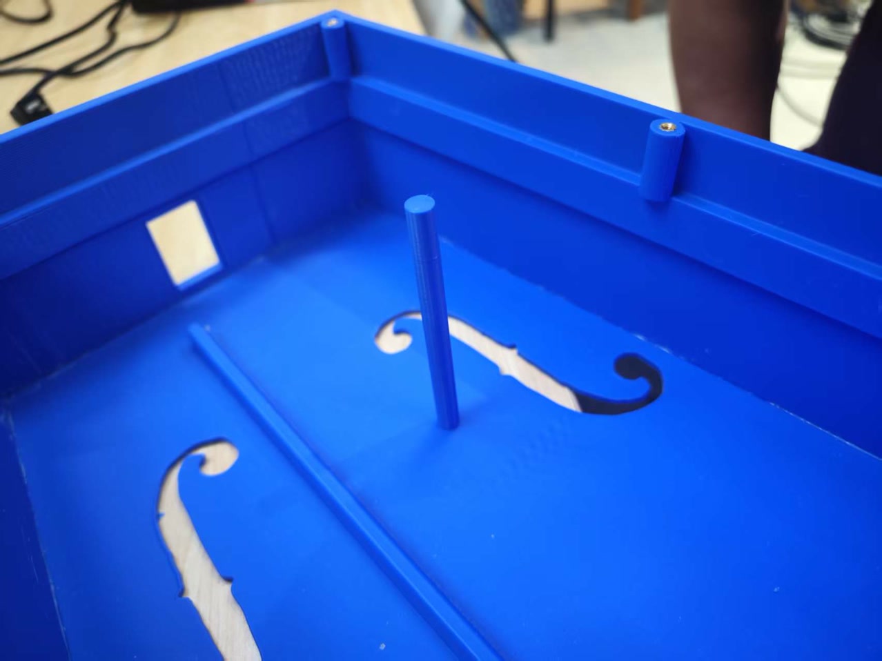
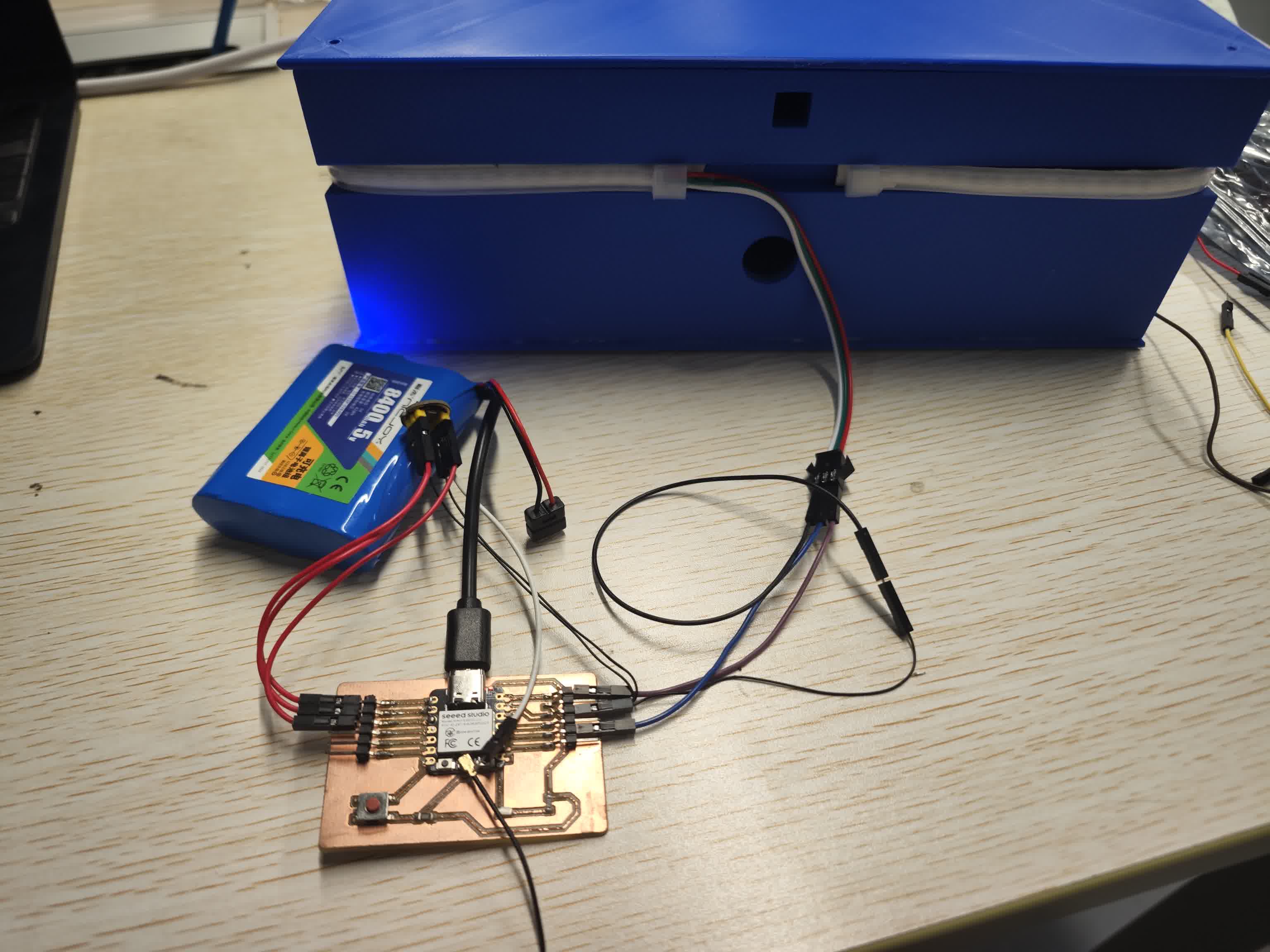
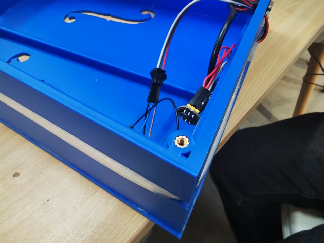
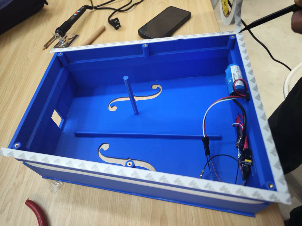
Step 3: Electronics Routing & Troubleshooting
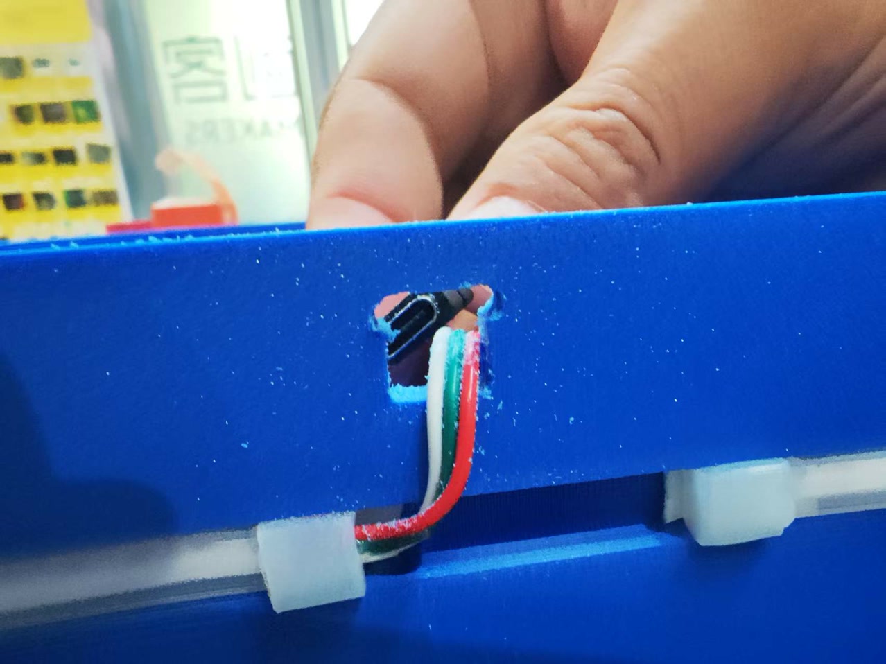
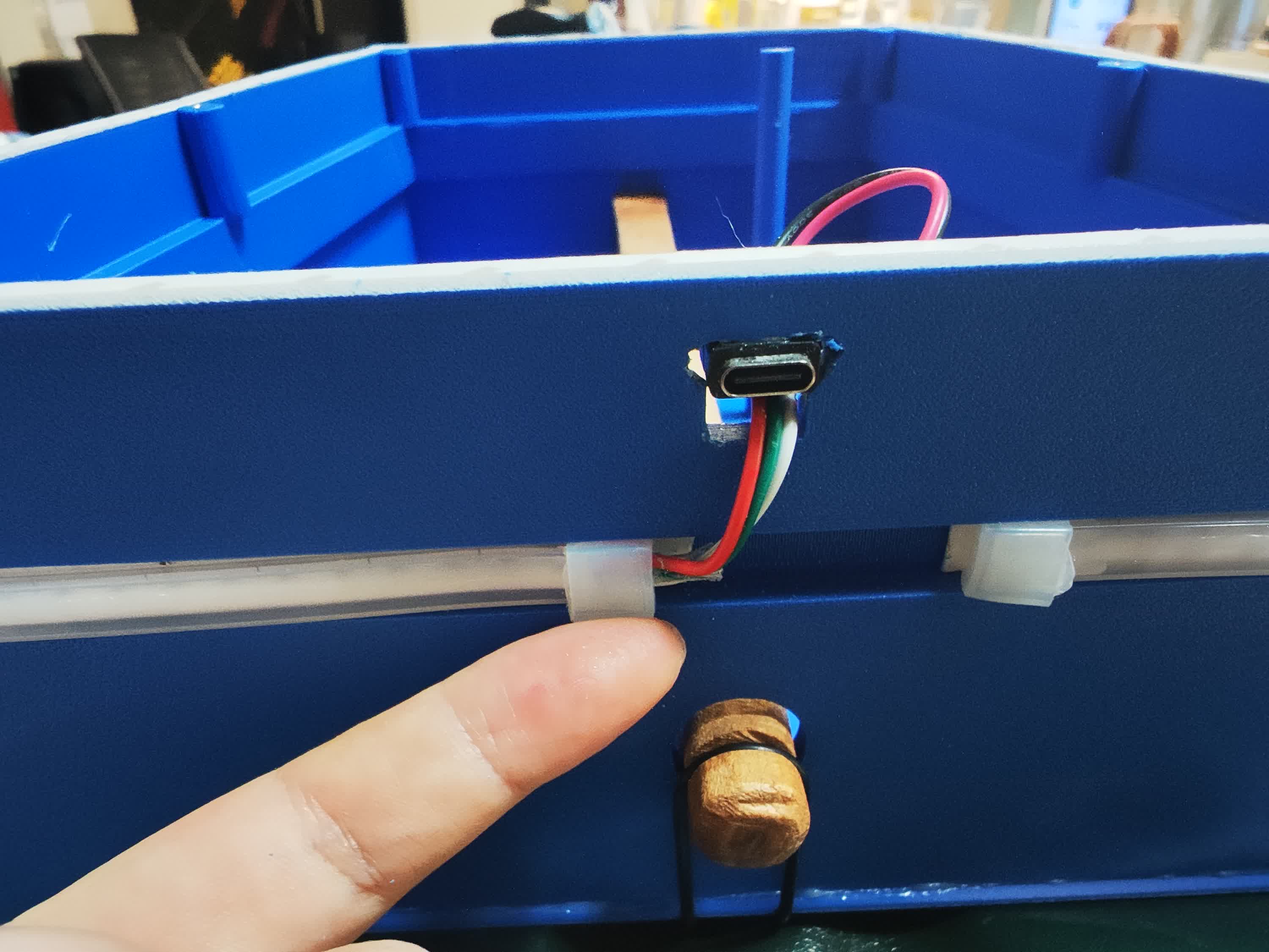
Next, I installed the internal hardware. The 1-meter WS2812 LED strip routed smoothly out of the hole and fit perfectly into the exterior groove. However, I hit a physical bug: my designed 10mm exit hole was too small to pass the battery's Type-C charging port. I had to manually widen the hole with a file, then secure the Type-C port flush with 401 glue.
I mounted the PCB and microphone module inside using easily removable nano tape. Crucial acoustic detail: I made absolutely sure no electronic components or wires touched the front panel, as it needs to vibrate completely freely to produce sound.
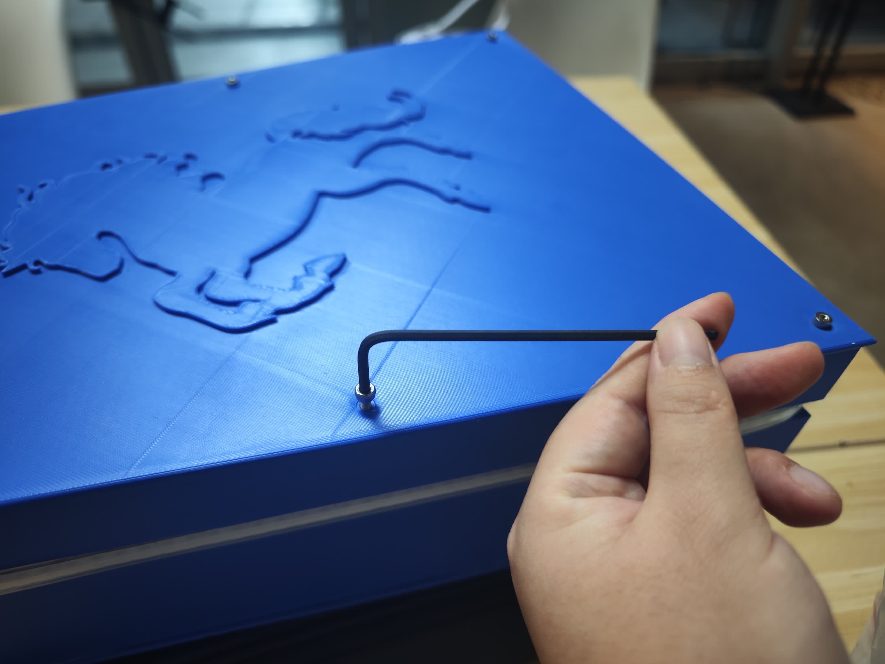
Step 4: The Heat-Set Inserts
This was a tense moment. As a non-engineering student, I researched this method specifically to make the back panel removable yet completely airtight.
Soldering Iron kit, M3 screws, M3 brass heat-set inserts:
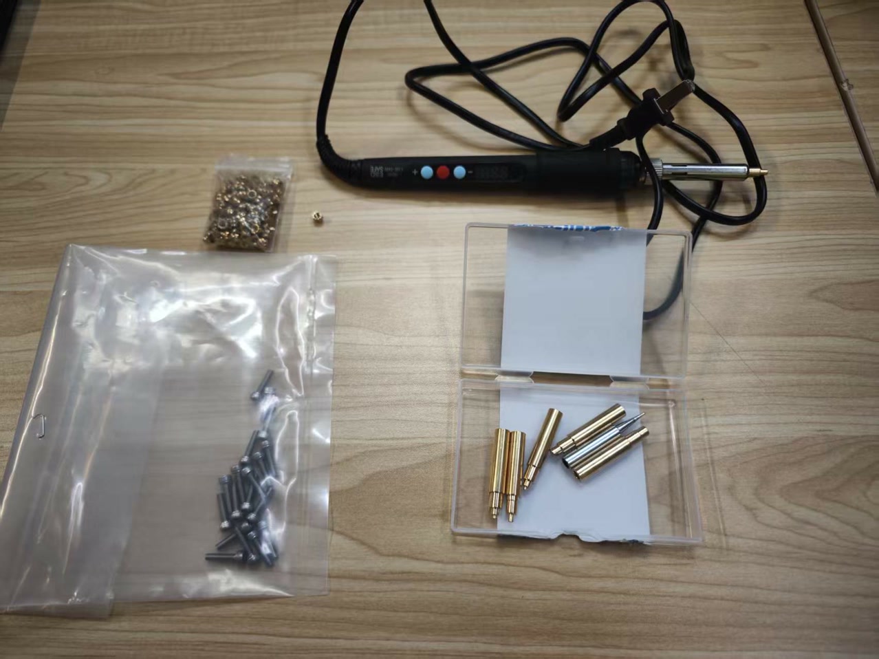
I set my soldering iron to 500°C and carefully pressed six M3 brass heat-set inserts vertically into the 3D-printed screw pillars. It melted in perfectly without damaging the plastic.
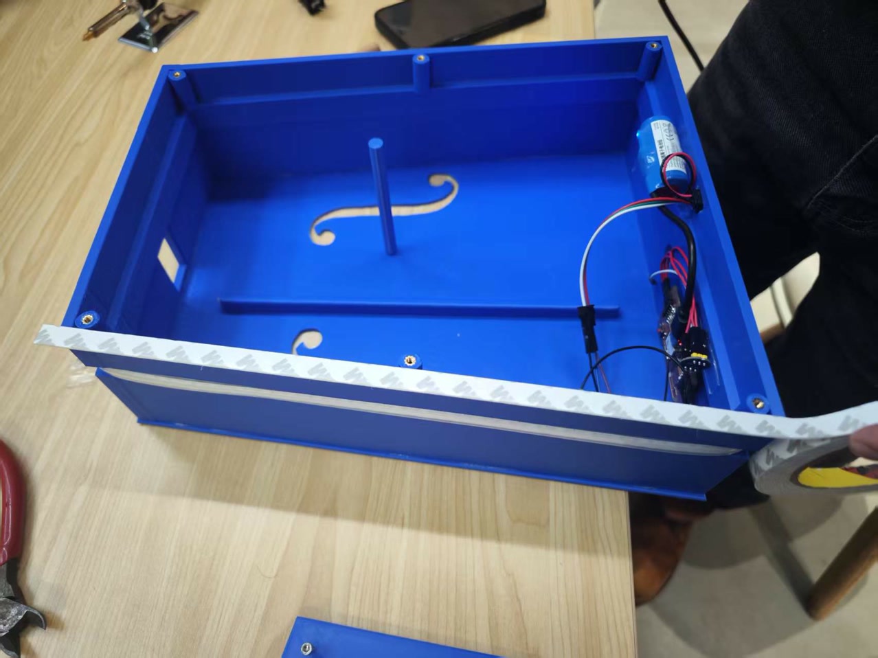
Step 5: Sealing the Acoustic Chamber
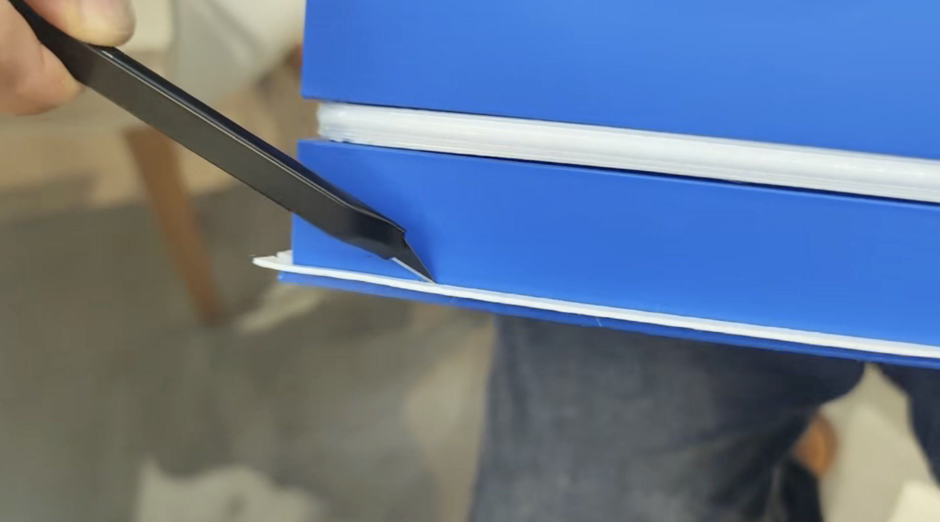
A back panel held by just six screws will leak air, which kills the sound. To solve this, I applied a continuous strip of 1mm thick, 10mm wide 3M acoustic foam tape along the 5mm interior rim of the middle frame.
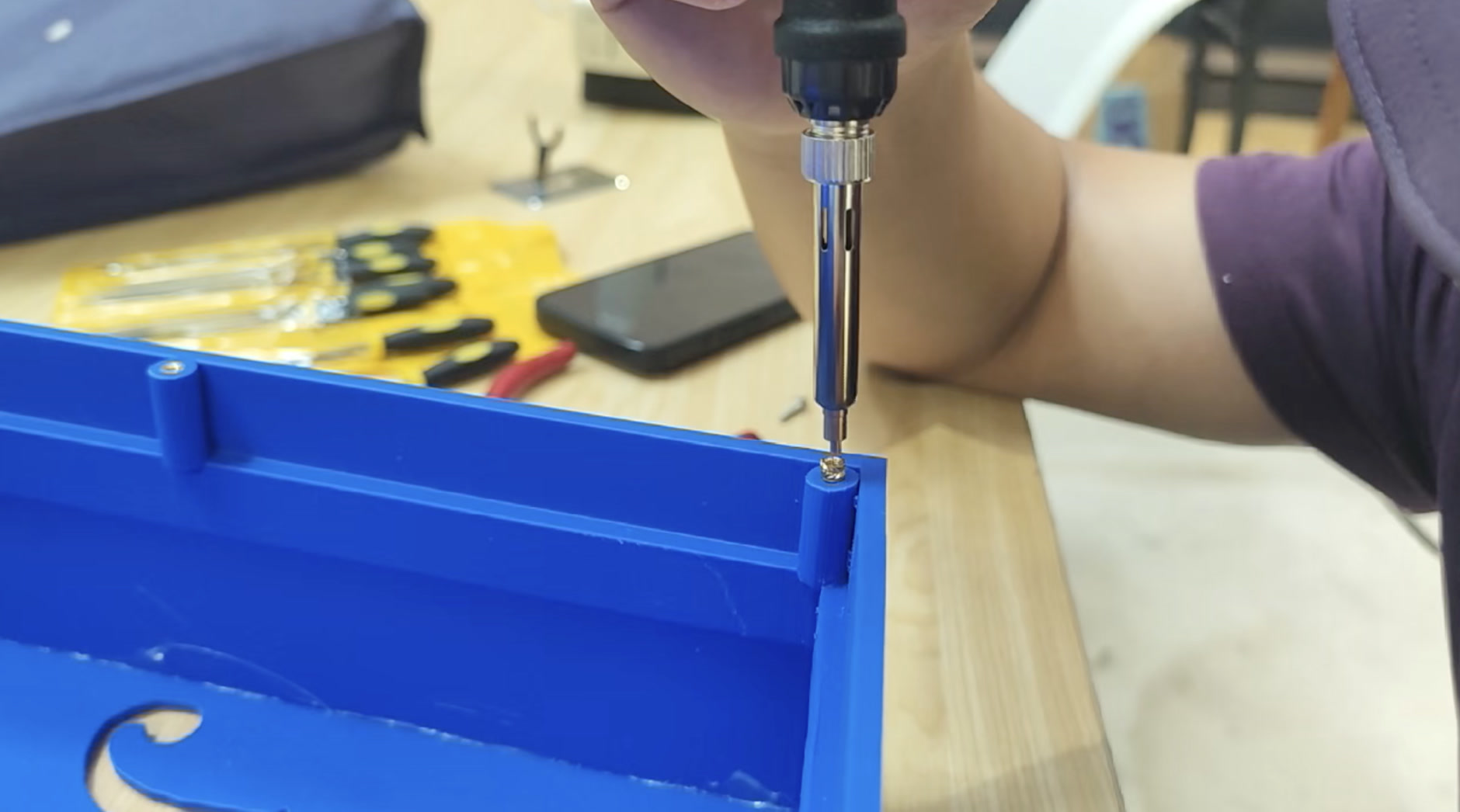
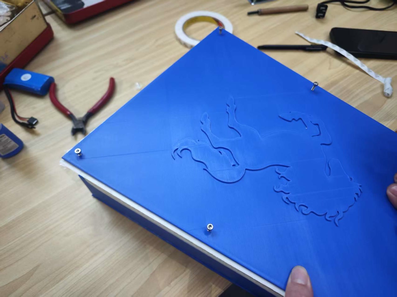
I tightly screwing in the back panel with six M3 screws.
I used a craft knife to carefully trim the excess 5mm of foam sticking out. The chamber was now perfectly sealed.
Then the acoustic box part was entirely integrated.
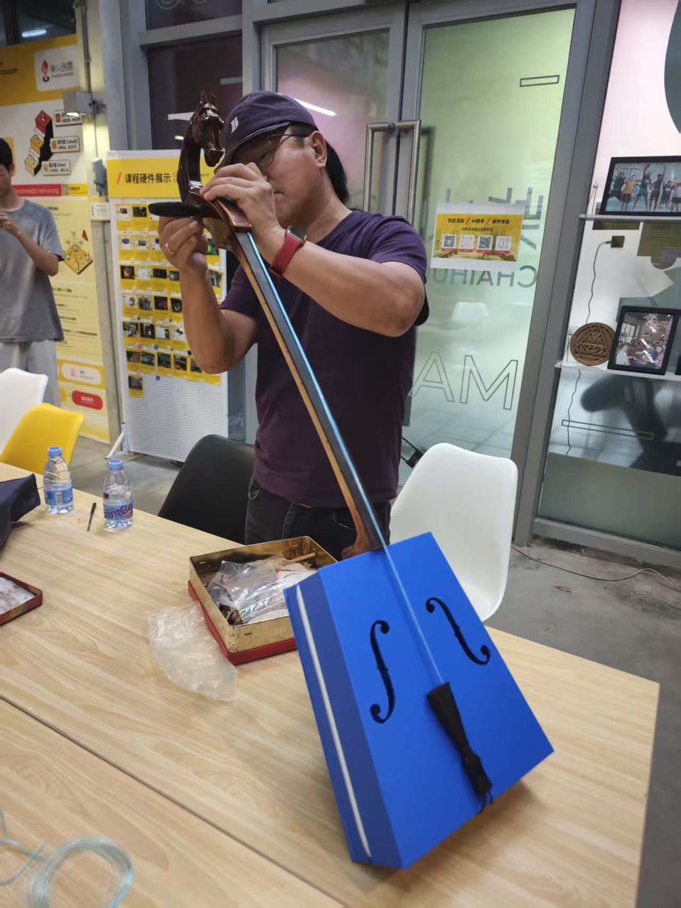
Step 6: Stringing and The First Note
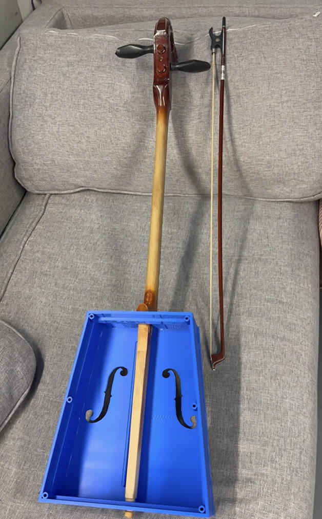
Since stringing a Morin Khuur requires specific expertise, I invited my Morin Khuur teacher, Mr. Habur, to help me install the strings and tailpiece together.
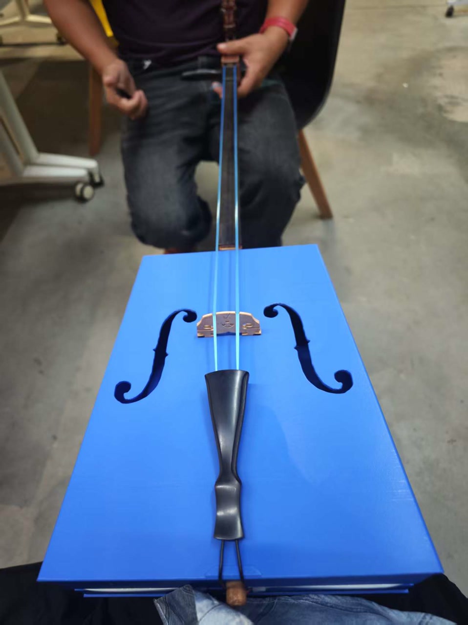
After the integration of wooden neck and strings, this new Morin Khuur was completed.
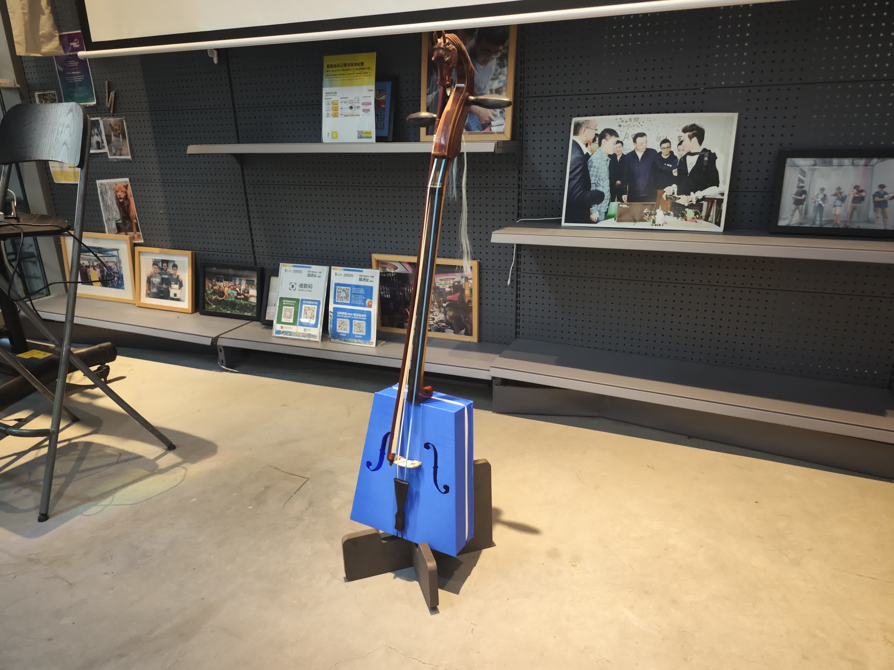
I tested this piece of Morin Khuur for the first time. The sound was thick, rich, and full of tension. It didn't sound "plastic" at all!

Then came the ultimate test. Mr. Habur played the first note, and we were both thrilled. The LED strip also reacted beautifully to the live playing, though I noted a few minor color and sensitivity glitches that I would later fix by tweaking the code. The 3D-printed acoustic design, the electronic parts, and the whole system integration seemed a success!