Week 11 — Group Assignment: Networking and Communications
Send a message between two projects.
This week we connect populated PCBs and microcontroller nodes from earlier weeks — wired and wireless — to exchange data between two boards. The group deliverable is direct node-to-node communication; the integrated MQTT + WiFi + LoRa chain below extends that toward the final-project solar PV system.
See assignment requirements for the full brief. Full code and walkthroughs: Timothy Mintargo's Week 11 documentation.
This page documents our Week 11 group collaboration at Chaihuo Makerspace. We built on the custom PCBs from Week 6 and Week 8, populated with XIAO modules, OLEDs, and Grove radios. Networking lets multiple boards exchange data while keeping power, signal, and radio subsystems modular.
Platform — PCB nodes connected
Each node combines:
- A populated carrier PCB or XIAO breakout with soldered headers
- I²C OLED (status display) on the designed SDA/SCL pins
- Wireless module — BLE (on-board ESP32), or Grove LoRa 868 MHz (UART)
- Common 3.3 V / 5 V rails and ground tied across probes and radios
Messages travel over the buses and radios we designed into the board — not loose breadboard jumpers.
Summary — earlier group experiments
Before the MQTT + LoRa integration, the cohort tested direct communication between two nodes:
| Experiment | Nodes | Bus / link | Result |
|---|---|---|---|
| Bluetooth BLE | 2× XIAO ESP32-C3 + OLED | BLE (2.4 GHz) | Server advertises; client scans and connects. Range ~10 cm without antenna, >10 m with two IPEX antennas. |
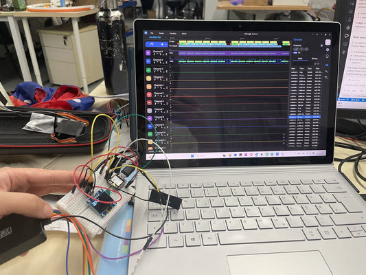
| I²C decode | XIAO ESP32-C3 + OLED | I²C (wired) | Logic analyzer captured 0x3C WR packets updating the OLED framebuffer. |
| SPI / RFID | Raspberry Pi 4 + MOSFET + LED | SPI (wired) | Proof-of-concept load switch; CS/CLK/MOSI/MISO visible on analyzer. |
Lessons from the earlier tests:
- Wireless needs both sides defined — server/client roles, reconnect logic, and OLED feedback
- Antennas matter — ESP32-C3 BLE without IPEX antenna is usable on the bench only
- I²C is wired networking — address byte + ACK; same decode skills as Week 9 scope work
- Two-node messaging is harder than one-direction UART — manage state on both microcontrollers
Wireless technology comparison (reference)
| Technology | Range | Frequency | Data rate | Internet |
|---|---|---|---|---|
| Wi-Fi | 50–100 m | 2.4 / 5 GHz | 10–600 Mbps | Yes (via AP) |
| Bluetooth BLE | 10–50 m | 2.4 GHz | 125 kbps–2 Mbps | Via gateway |
| LoRa | 2–15 km | 433 / 868 / 915 MHz | 0.3–50 kbps | No (needs LoRaWAN) |
Higher frequency → more data, shorter range. LoRa trades speed for distance — good for field nodes that should not depend on Wi-Fi.
Wired/wireless integration — MQTT + WiFi + LoRa��
Taking the two-node work further, we tested wireless communication between multiple units of the solar PV final-project concept: location detection and bidirectional command exchange. A WiFi + LoRa combination was chosen as robust for mixed indoor/outdoor use. Because cloud services and a payment system are planned later, MQTT was added so the embedded chain mirrors a realistic IoT publish/subscribe flow.
Content adapted from Timothy Mintargo's Week 11 — wired/wireless integration.
Basics of MQTT
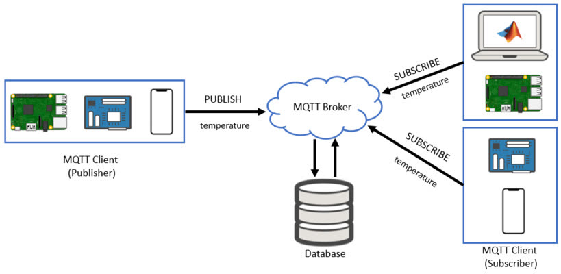
MQTT (Message Queuing Telemetry Transport) uses a publish/subscribe model:
| Role | Function |
|---|---|
| Broker | Central server (we used Mosquitto) — receives and routes messages |
| Publisher | Sends messages to a topic (e.g. lora/tx) |
| Subscriber | Receives messages from topics it subscribed to |
Devices do not talk to each other directly — they talk through the broker. This decouples the WiFi-connected node from the LoRa-only node.
Minimal mosquitto.conf for lab testing:
listener 1883
allow_anonymous true
Start the broker: mosquitto -c mosquitto.conf -v
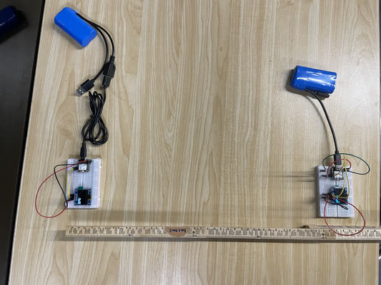
Two-node setup
| Node (left) | Node (right) |
|---|---|
| XIAO ESP32-C3 + Grove LoRa 868 MHz + OLED | XIAO RP2040 + Grove LoRa 868 MHz + OLED |
| WiFi + MQTT subscriber | LoRa receiver only |
| Forwards MQTT messages over LoRa UART | Processes commands on display |
The RP2040 has no built-in Wi-Fi — it depends on LoRa from the ESP32-C3, reducing reliance on internet at the remote node.
LoRa wiring (both boards):
| LoRa pin | XIAO pin |
|---|---|
| TX | D7 (MCU RX) |
| RX | D6 (MCU TX) |
| VCC | 3.3 V |
| GND | GND |
OLED (I²C, both boards): SDA → D4, SCL → D5
Flow:
- ESP32-C3 connects to WiFi and subscribes to MQTT topic
lora/tx - PC publishes via
mosquitto_pub→ broker → ESP32-C3 callback - ESP32-C3 forwards the string over LoRa UART to RP2040
- RP2040 shows the message on OLED
Full firmware for both boards is in Timothy's Week 11 page (ESP32-C3: WiFi + PubSubClient + Serial1; RP2040: RadioHead RH_RF95 receiver + OLED).
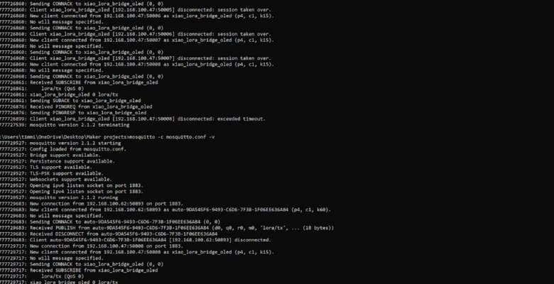
Running the broker and sending messages
After uploading firmware, start Mosquitto in one terminal. Status messages confirm the broker is listening on port 1883.
Open a second terminal and publish test commands:
mosquitto_pub -t "lora/tx" -m "Hello ESP32"
mosquitto_pub -t "lora/tx" -m "turn on the system"
mosquitto_pub -t "lora/tx" -m "turn off the system"
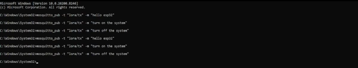
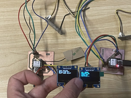
The ESP32-C3 receives each message and relays it over LoRa; the RP2040 OLED updates with the text.
End-to-end demo: MQTT publish on PC → ESP32-C3 → LoRa → RP2040 OLED.
What we learned
- PCB nodes are the integration point. Radios and OLEDs mount on the same boards we designed and fabricated — networking tests the full stack, not just a dev kit on a breadboard.
- Pick the link for the job. BLE for short-range peer pairing; LoRa for longer range without Wi-Fi; MQTT when a PC or cloud service must inject commands.
- Brokers decouple nodes. The ESP32-C3 and RP2040 never need a direct IP path to each other — only to the broker (ESP32) and LoRa link (both).
- Antennas and UART wiring are part of the design. Swapped TX/RX or missing IPEX antenna shows up immediately as silent radios or dropped BLE.
- Test with known strings first.
Hello ESP32,turn on the system,turn off the systemmade it obvious when each hop in the chain worked.
These group findings feed into each student's individual assignment: design, build, and connect wired or wireless node(s) with bus addresses and local I/O on your own PCB.