Week 7 — Group Assignment: Computer-Controlled Machining
Characterise the lab CNC machine before anyone cuts a final part:
- Complete your lab's safety training
- Test runout, alignment, fixturing, speeds, feeds, materials and toolpaths for your machine
- Document your work on this group page and reflect on what you learned on your individual page
The individual assignment for this week is to make something big (~meter-scale): design, mill, and assemble it. See assignment requirements for details.
This page documents our Week 7 group collaboration at Chaihuo Makerspace to characterise the CNC router: safety training, machine setup, test cuts, and the working parameters we measured. The numbers here fed directly into each student's individual assignment.
Safety Training
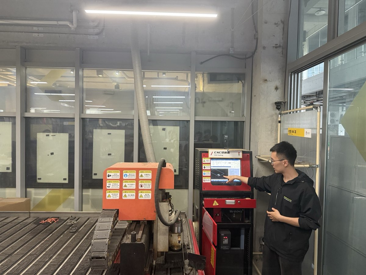
We did not skip the safety training even though some of us had seen a CNC machine before. Instructor Matthew walked us through the full safety checklist before anyone touched the machine.
Checklist covered:
- Machine safety basics and standard operating procedure
- Emergency stop location — everyone confirmed they could find it without looking
- Protective guards functional
- No loose clothing or gloves near the spindle
- No hands on the table during operation
- Board must be fully secured before the job starts
- Check the bit for chipping or wobble before running
- Dust and noise protection — masks, hearing protection, dust collector running
 |  |
|---|
Standing next to a machine that size feels different from reading the rules on paper. The safety training is what made the rest of the week's cuts possible without incident.
Our CNC Machine
The CNC router at Chaihuo is a Tiancheng Xinli 3STX-1325A-style machine.
| Specification | Details |
|---|---|
| Manufacturer | Tiancheng Xinli CNC |
| Model | 3STX-1325A |
| Working area (X × Y) | 1300 mm × 2500 mm |
| Z-axis travel | 180 mm |
| Spindle speed range | 0 – 24000 rpm |
| Spindle power | 3 kW water-cooled |
| Control file format | G-code / UPP / nc |
| Max feed rate (cutting) | 15000 mm/min |
| Positioning accuracy | ±0.15 mm / 300 mm |
Material
For characterization we used high-density fiberboard (HDF):
| Property | Value |
|---|---|
| Nominal thickness | 18 mm |
| Measured actual thickness | 18.3 mm |
| Board size | 1220 mm × 2440 mm |
We measured the real board thickness with calipers before starting — nominal sizes are not always accurate, and the real number matters for joint design. The boards are heavy; it took four or five of us to carry one sheet safely.
Machine Setup
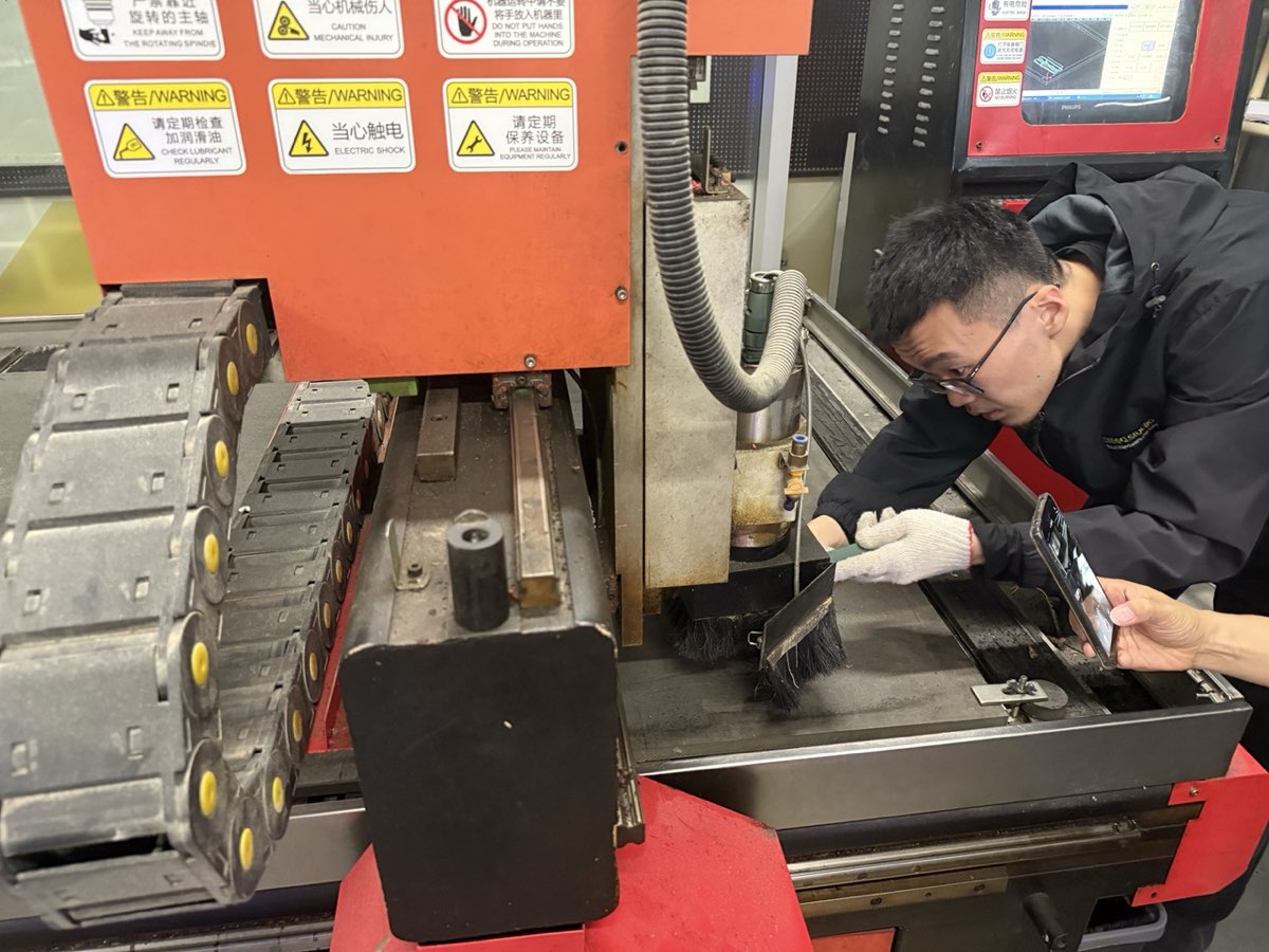
Cleaning and securing the workpiece
We cleaned the table before placing the board. Even small chips can tilt the board and cause uneven cutting depth. The board was clamped at the edges with fasteners screwed into a sacrificial layer, keeping clamps outside the cutting area.
Setting the origin (X / Y / Z zero)
We jogged the spindle to the front-left corner of the board and set X/Y zero there. For Z, we lowered the bit until it just touched the top surface of the board (not the machine bed) and zeroed Z. If the board is not perfectly flat, cuts that look uniform in the file can come out shallower on one side — setting Z relative to the actual board surface avoids that.
CAM Setup — MasterCAM
We prepared toolpaths in MasterCAM X6 for the Week 7 characterization file and individual press-fit projects (e.g. Little Dog Bed V1.2). The workflow was: import or draw 2D geometry → assign a 2D Contour toolpath → set tool, speeds/feeds, cutting parameters, and depth → simulate → post to G-code for the Tiancheng Xinli controller.
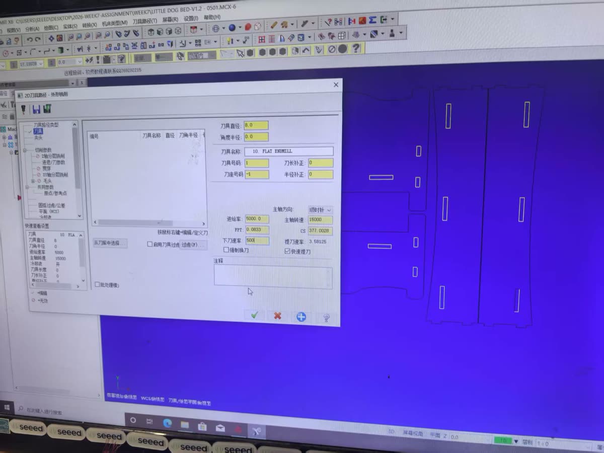
Tool, speeds and feeds
For the characterization cuts we used an 8 mm flat end mill (Tool #1) with these values in MasterCAM:
| Parameter | Value |
|---|---|
| Tool | 8 mm flat end mill |
| Spindle speed | 15000 rpm |
| Feed rate | 5000 mm/min |
| Plunge rate | 500 mm/min |
| Spindle direction | Clockwise |
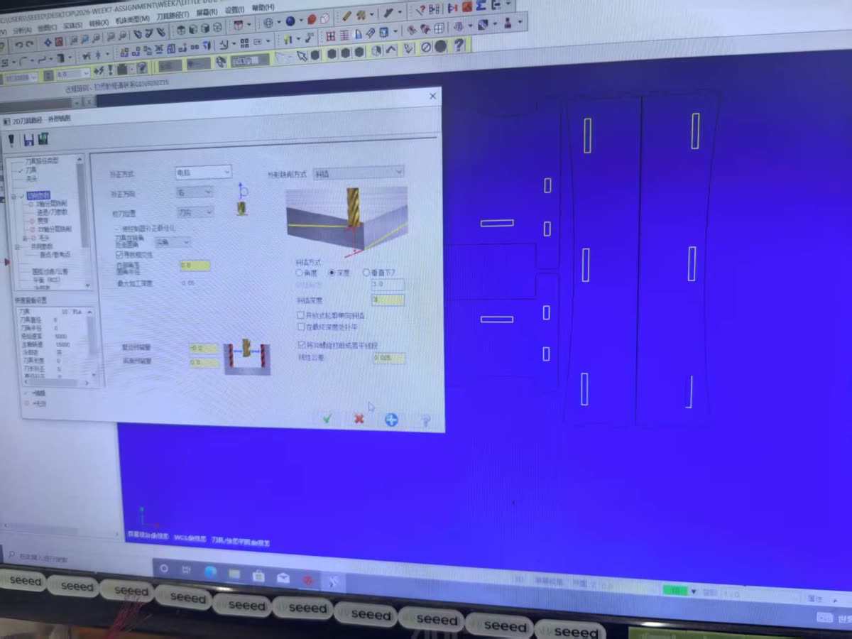
Cutting parameters
Contour compensation was set to computer / left so MasterCAM offsets the toolpath correctly for an outside cut. We left −0.2 mm on walls to account for kerf and press-fit tolerance; floor stock was 0. Ramp entry used a 3 mm depth with 0.025 mm linear tolerance.
| Parameter | Value |
|---|---|
| Compensation | Computer, left |
| Stock to leave (walls) | −0.2 mm |
| Stock to leave (floors) | 0.0 mm |
| Ramp depth | 3.0 mm |
| Linear tolerance | 0.025 mm |
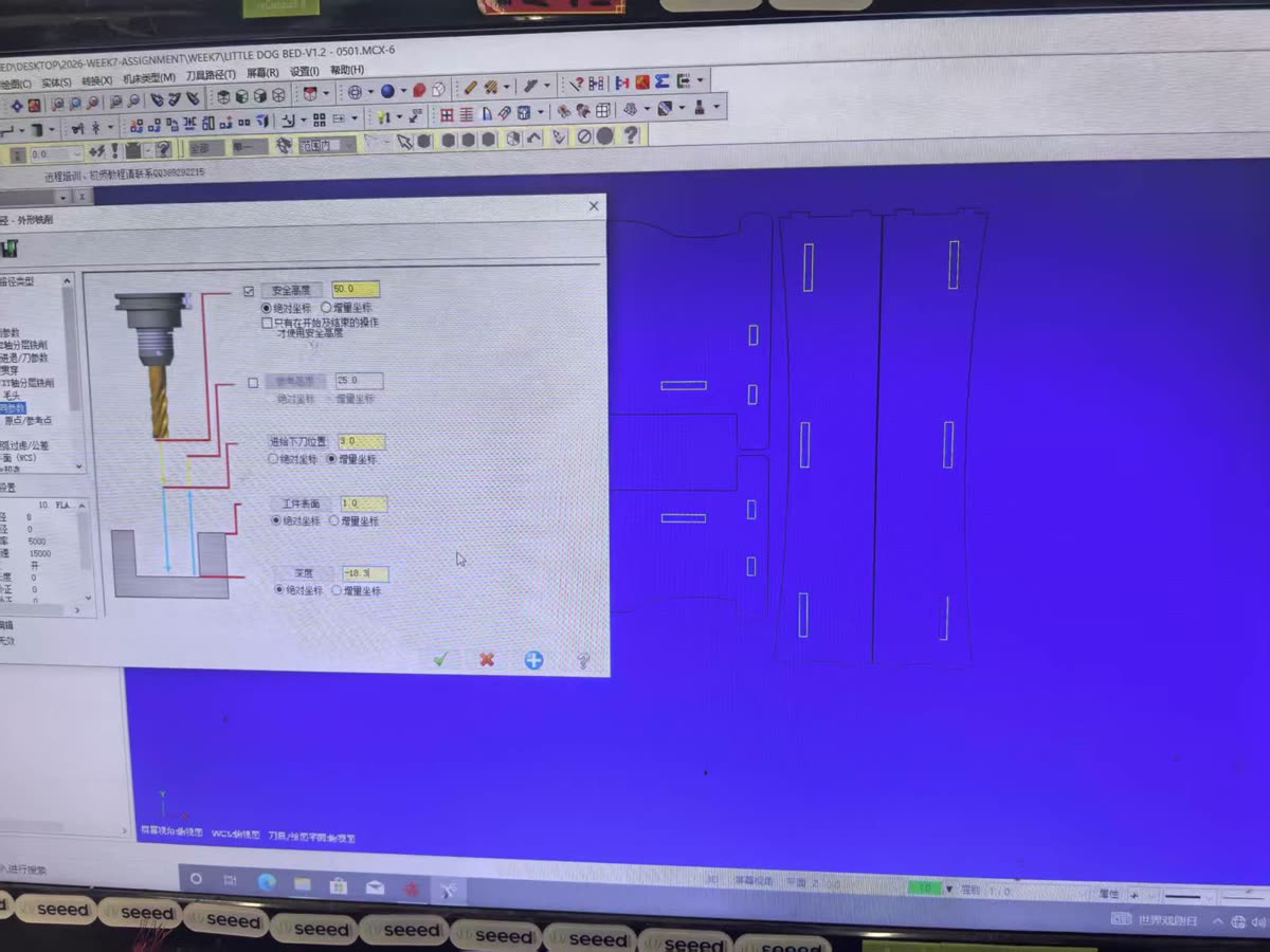
Depth and clearance heights
Cut depth was set from the measured board thickness. Top of stock was 1.0 mm (absolute); final depth −18.3 mm matches the caliper reading on our HDF sheet. Safety and reference heights keep the tool clear of the workpiece during rapid moves.
| Parameter | Value | Mode |
|---|---|---|
| Safety height | 50.0 mm | Absolute |
| Reference height | 25.0 mm | Absolute |
| Feed plane | 3.0 mm | Incremental |
| Top of stock | 1.0 mm | Absolute |
| Cut depth | −18.3 mm | Absolute |
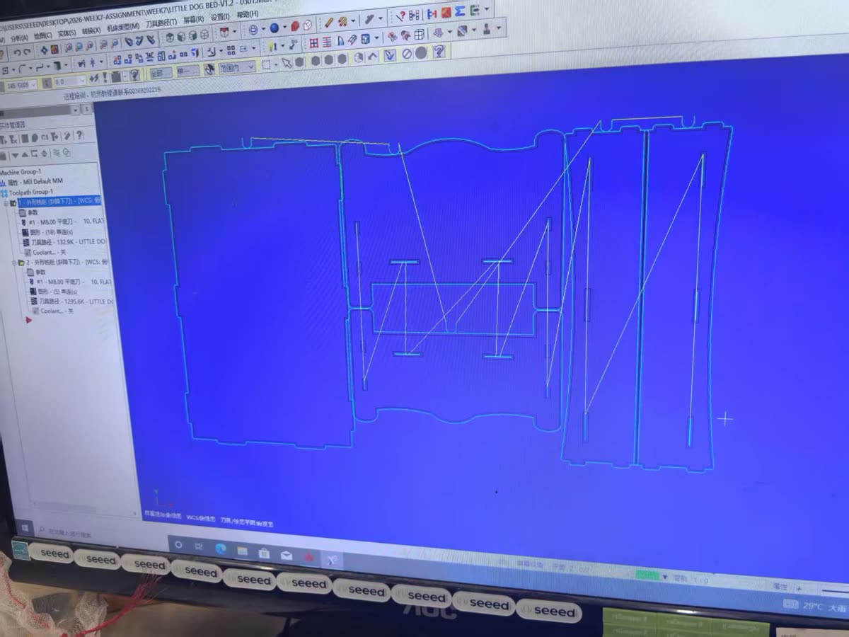
Toolpath simulation
After setting parameters we ran the toolpath simulation in MasterCAM. The screenshot below shows the nested press-fit panels for the dog-bed test layout — outer contours, internal slots, and rapid moves between chains — before posting G-code to the machine.
Machine Characterization
The group assignment asks us to test runout, alignment, fixturing, speeds, feeds, materials, and toolpaths before cutting final parts. Here is what we checked and what we found.
Runout
We inspected spindle/tool rotation for eccentricity before the first cut. A damaged or wobbly bit does not just cut poorly — it can break under load. We replaced one bit that showed visible chipping before running the test file.
Alignment and fixturing
Workpiece alignment was verified by confirming the board sat flat on the table and that clamp positions did not intrude into the toolpath. Coordinates were calibrated at the board corner origin described above. Any movement of the workpiece mid-cut means a ruined part at best and a safety hazard at worst, so we re-checked clamping after every board move.
Speeds, feeds, materials and toolpaths
We designed a test file with rectangular pockets and contour cuts at different feed rates, a kerf measurement slot, and press-fit slots with graduated tolerances. The MasterCAM settings above (15000 rpm, 5000 mm/min feed) were used for the main characterization run; we also tried lower feed rates on separate test pieces to compare edge quality.
Toolpath settings used for characterization (see CAM Setup — MasterCAM above for screenshots):
| Parameter | Value used |
|---|---|
| CAM software | MasterCAM X6 |
| Toolpath type | 2D contour |
| Tool diameter | 8 mm flat end mill (characterization) / 6 mm (recommended for final parts) |
| Spindle speed | 15000 rpm |
| Feed rate (cutting) | 5000 mm/min |
| Plunge rate | 500 mm/min |
| Cut depth | −18.3 mm (measured board thickness) |
| Wall stock offset | −0.2 mm |
| Cut order | inside before outside, small before large |
What changed across the test runs:
- Higher feed rates produced noticeably rougher edges on the exit side
- The lowest feed rate showed slight discoloration at corners, suggesting heat buildup
- Cutting in multiple shallow passes gave more consistent walls than a single full-depth pass at 18 mm
- For press-fit joints, inside corners need dog-bone reliefs — a round bit cannot cut a true 90° inside corner, so a mating square corner will not seat fully without compensation
| Parameter | Unit | Controls | Rule of thumb |
|---|---|---|---|
| Tool diameter | mm | Cut width | Larger Ø = wider cut |
| Spindle speed | RPM | Tool rotation speed | Harder material → lower RPM |
| Feed rate | mm/min | Tool traverse speed | Balance with spindle speed |
| Depth of cut | mm | Material removal per pass | Deep cuts → multiple passes |
Summary of Recommended Parameters
After all the tests, these are the settings we found to work well for HDF/MDF on our machine:
| Parameter | Recommended value |
|---|---|
| Material | HDF / MDF, ~18.3 mm (measure each sheet) |
| Bit diameter | 6 mm flat end mill |
| Spindle speed | 24000 rpm |
| Feed rate | 2000 mm/min |
| Plunge rate | 1000 mm/min |
| Depth per pass | 6 mm |
| Tabs | 3 mm tall, 5 mm wide, placed at corners |
| Press-fit slot offset | −0.4 mm per side vs. measured board thickness |
| Kerf (average) | ~0.4 mm |
| Dog-bone radius | bit radius = 3 mm |
What We Learned
- Measure the real board thickness. Ours was 18.3 mm, not 18.0 mm. Design joints from caliper readings, not the label.
- Kerf compensation belongs in the design. The machine removes more material than the bit diameter alone suggests. For receiving slots, add half the kerf to each side.
- Inside corners always need attention. Design for dog-bones or extend slots slightly at each end.
- Feed rate affects quality, not just cycle time. Too slow burned corners; too fast roughened edges. Find the middle range for your material and bit before the final cut.
- Cut order matters. Inside before outside, small before large — keeps the workpiece stable until the last pass.
- Secure the board every time. A shifting board ruins the job and is a safety issue.
These numbers came from actual cuts, measurements, and a few mistakes — the kind of reference we actually trust going into the individual assignment.