Week 6 — Group Assignment: Embedded Programming
This week group assignment focuses on use electronic measurement tools. These include the multimeter, oscilloscope, and logic analyzer. Understanding how to use these tools is essential for anyone working with electronic circuits.
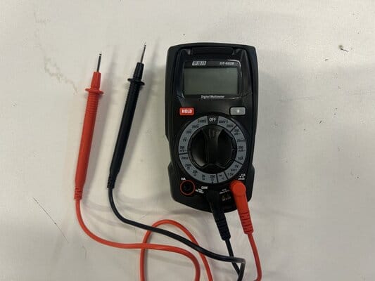
1.1 Multimeter
The multimeter is a measuring instrument for electrical properties: Voltage (V), Current (A), and Resistance (Ω).
- Display – shows negative values
- Selection Knob – choose V, A, Ω, or continuity test
- 3 Ports:
10A (left) – for currents >200mA
COM (middle) – black probe, circuit ground
VΩmA (right) – red probe, for voltage, resistance, and currents ≤200mA
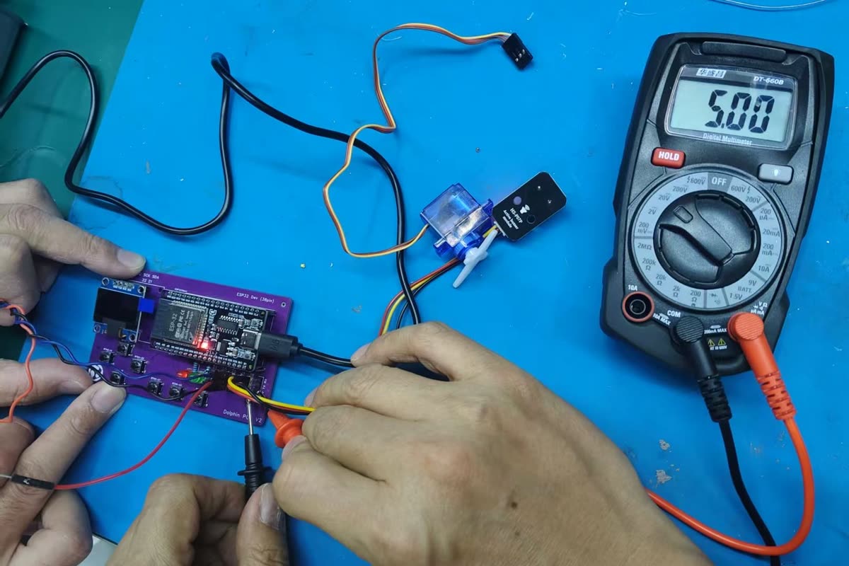
1.1.1 Multimeter Measure Voltage
- Voltage – the electrical potential difference between two points.
- How to measure: Connect the multimeter in parallel across the component.
I measured the voltage between GND and VCC pins on the ESP32. It displayed 5.00V.
- Voltage measurement:
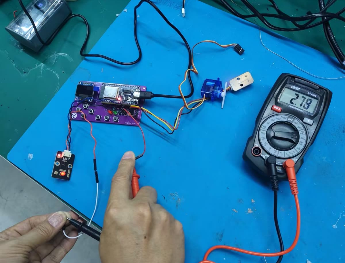
1.1.2 Multimeter Measure Current
Current – the flow of electric charge through a circuit. How to measure: Insert the multimeter in series with the component (break the path and place the meter in between).
I measured the current between GPIO 19 and GND pins on the ESP32. It displayed 2.78 mA.
-
Current measurement:
-
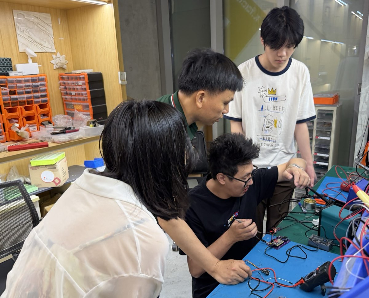
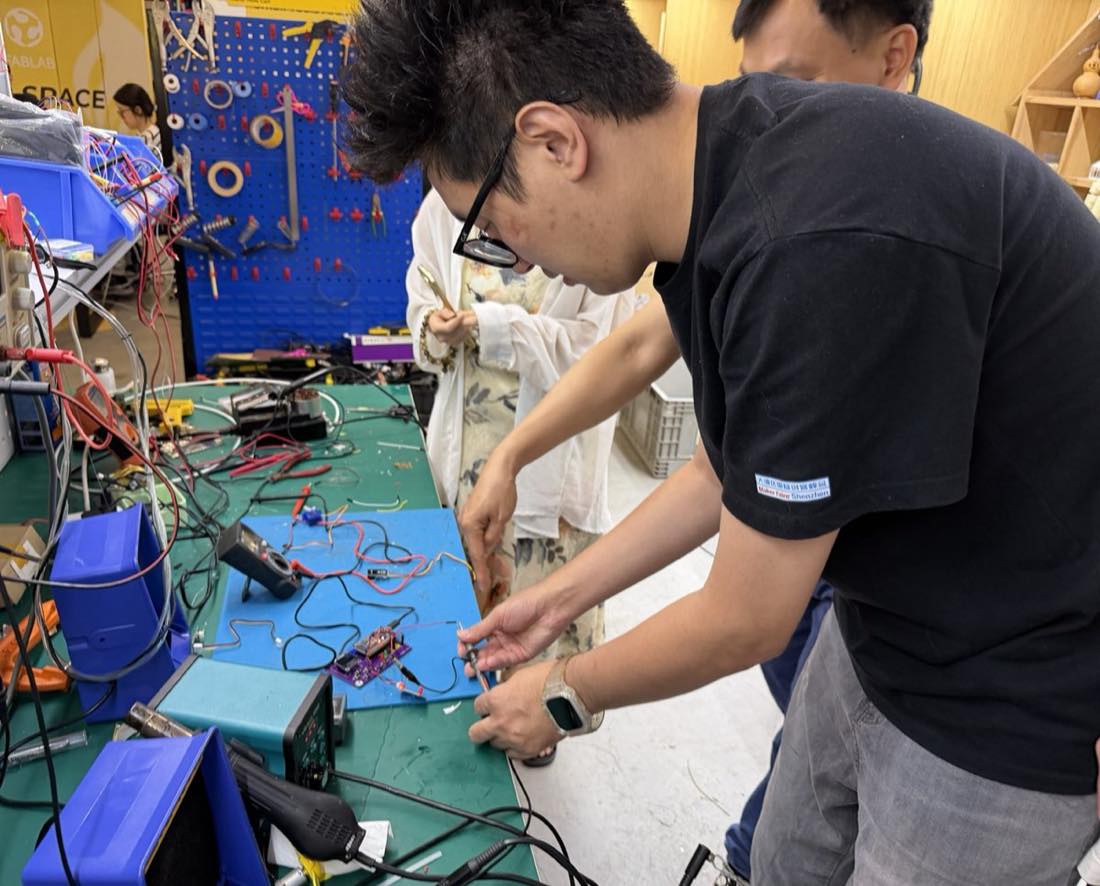
Group using multimeter:
1.2 Oscilloscope
Oscilloscope – a device that displays electrical signals as waveforms.
- Y-axis: Voltage
- X-axis: Time
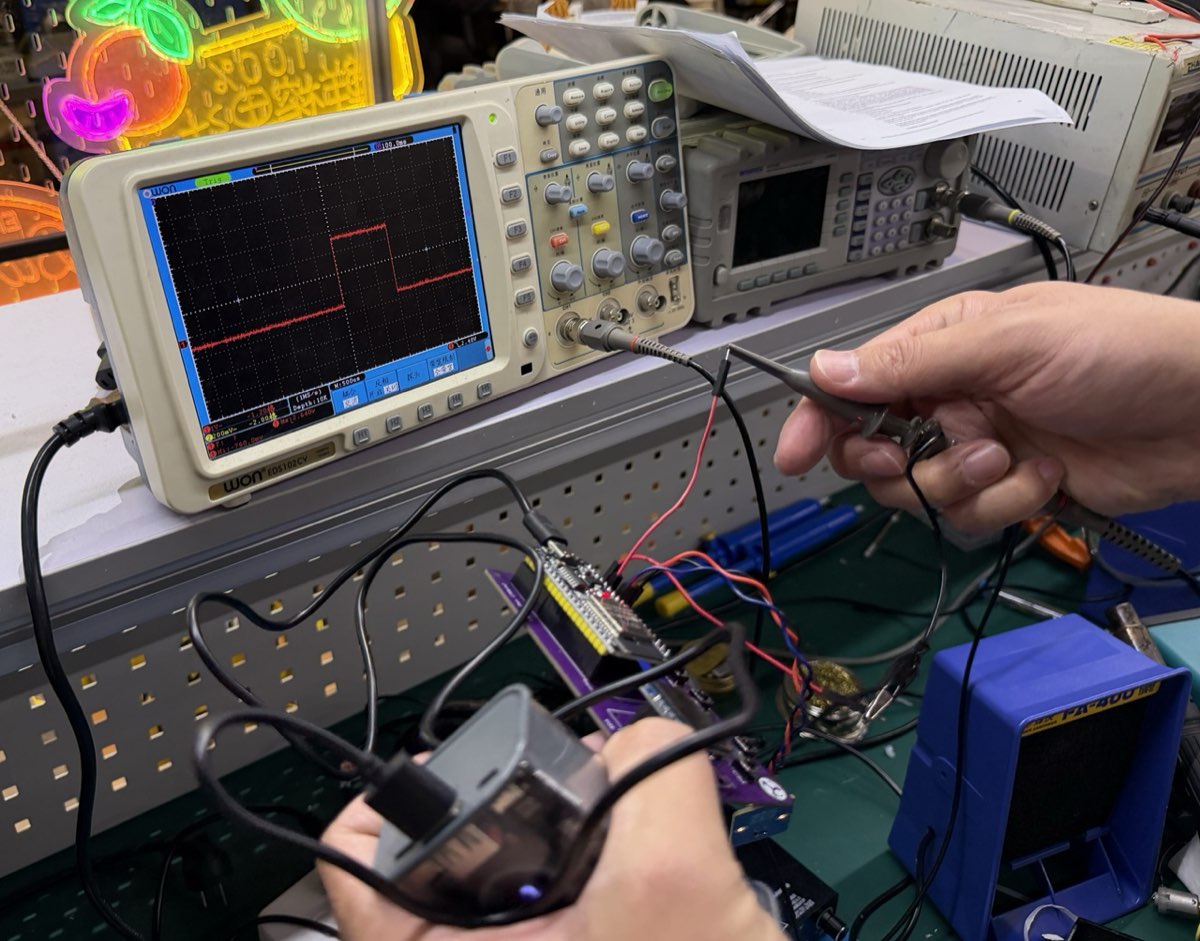
1.2.1 Measure Servo Signal
I connected a servo motor to the ESP32 and programmed it to rotate to 90°, 0°, and -90° positions. The oscilloscope was used to measure the servo control signal (PWM).
-
esp32 connect servo and rotate
-
Oscilloscope measurement