Week 12 — XIAO Vending Machine
Now launched — How to Vend Almost Anything
What started as our Week 12 Fab Academy prototype is now a fully working four-column machine with a live PC backend, RFID writer, inventory tracking, and two real dispense modes. The open-source release is live:
Seeed-Studio/how-to-vend-almost-anything
Operators write cards from a dashboard; customers tap the machine. Any product family that shares one shape and form can ride the same column + bus-servo architecture — this XIAO machine is the reference for that bigger idea.
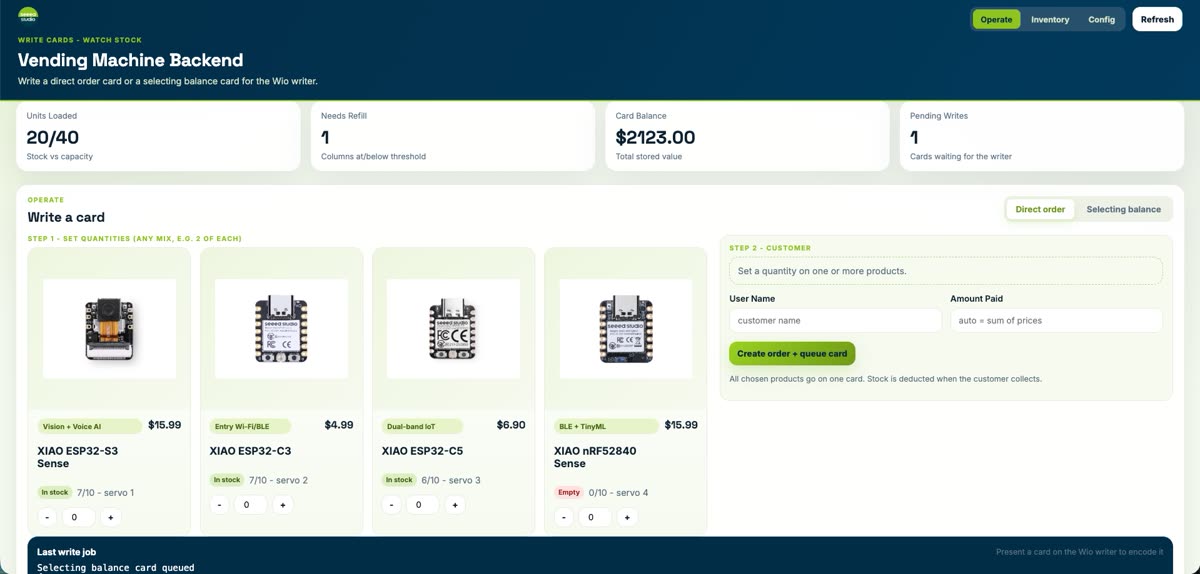
Live backend dashboard (Operate): write a direct order card or a selecting balance card, watch stock, and queue the Wio RFID writer.
Two dispense modes — real operation
| Mode | Card | At the machine |
|---|---|---|
| Direct order | Pre-paid SKU + quantity | Tap → dispenses that order immediately |
| Selecting balance | Stored value on the card | Tap → LCD menu → customer picks a column |
Direct order
Tap the Order card → column / serve status on the Wio → servo gate releases the product.
Selecting balance
Tap the Balance card → four-column menu on the LCD → select → dispense + backend balance update.
Full dashboard walkthrough, inventory/config pages, and end-to-end flow: §9 From Prototype to Full System.
The Week 12 prototype (origin story)
For the machine design group assignment, our team designed and prototyped a vending machine for selling Seeed Studio XIAO Series development boards — ideation, planning, component selection, and the first working dispense loop.
That early pipeline: a user taps a pre-programmed RFID card, a Wio Terminal reads it over I2C, verifies the embedded credit token, and — only if the card carries the TRUE payload — drives STS3215 serial-bus servos to swing the column gates and drop a board into the chute. Every step is mirrored on the built-in LCD.
The sections below document that journey: brainstorm, architecture, BOM, subsystem testing, mechanical integration, wiring, and the first complete prototype demo.

Week 12 prototype demo: card tap → authentication → servo dispense → XIAO board delivered.
1. Idea Generation
We started by brainstorming what kind of machine would be useful in a makerspace context. The idea of a vending machine for XIAO boards came up quickly — it solves a real problem: making dev boards available to makers on demand, without staffing a counter.
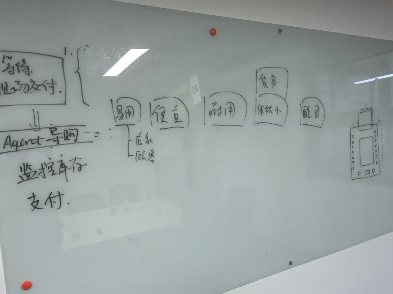
The team's initial brainstorming session. We outlined the system flow: user authentication, payment, inventory monitoring, and product dispensing.
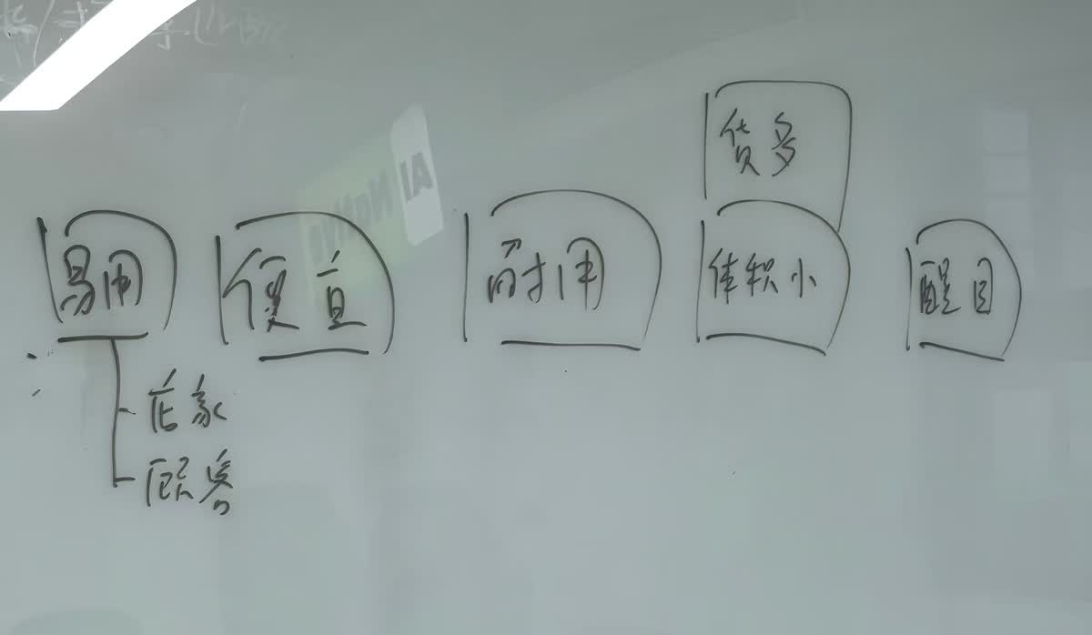
From the brainstorm, we converged on a set of core requirements for the machine:
| Requirement | Description |
|---|---|
| Easy to use (易用) | Simple tap-and-go interaction via RFID card |
| Affordable (便宜) | Low-cost components, reuse of makerspace materials |
| Durable (耐用) | Robust mechanical structure for repeated use |
| Compact (体积小) | Small footprint suitable for a desk or counter |
| Eye-catching (醒目) | Transparent acrylic case to showcase the products inside |
The machine would support both in-store and remote purchasing (via an agent system), with inventory monitoring and a digital payment flow.
2. Planning and Design
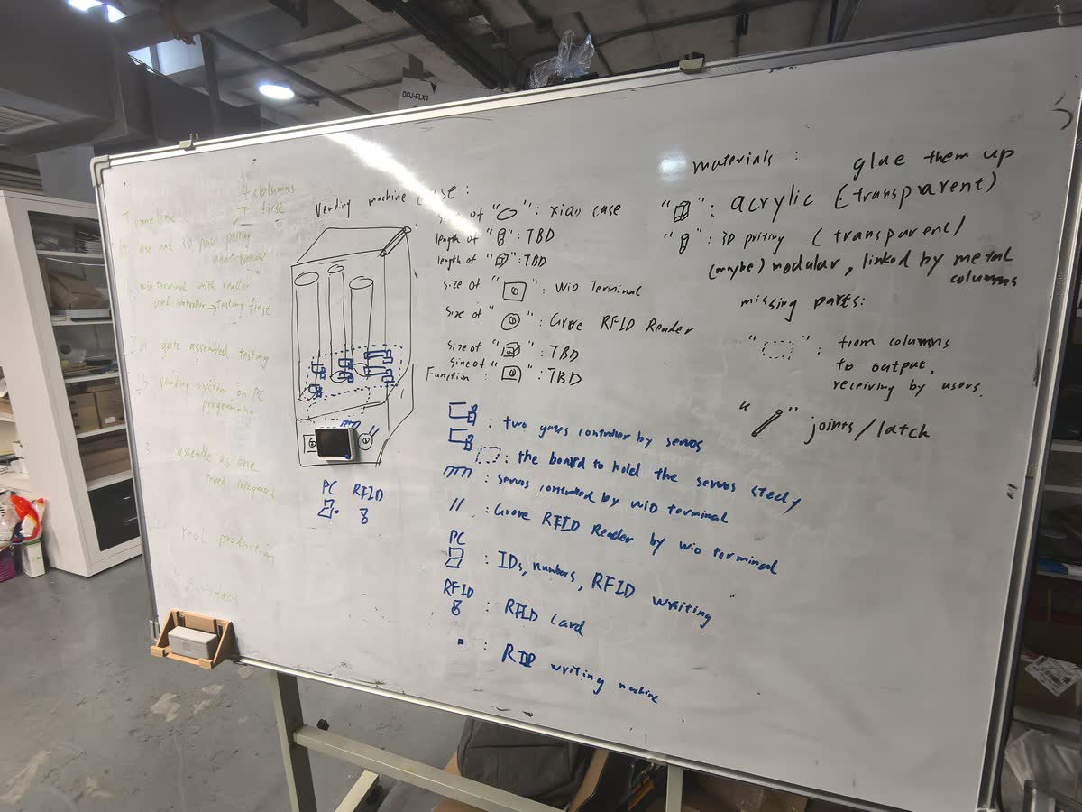
With the concept locked, we moved to detailed planning. The whiteboard below captures our full design — timeline, case sketch, component legend, and materials list.
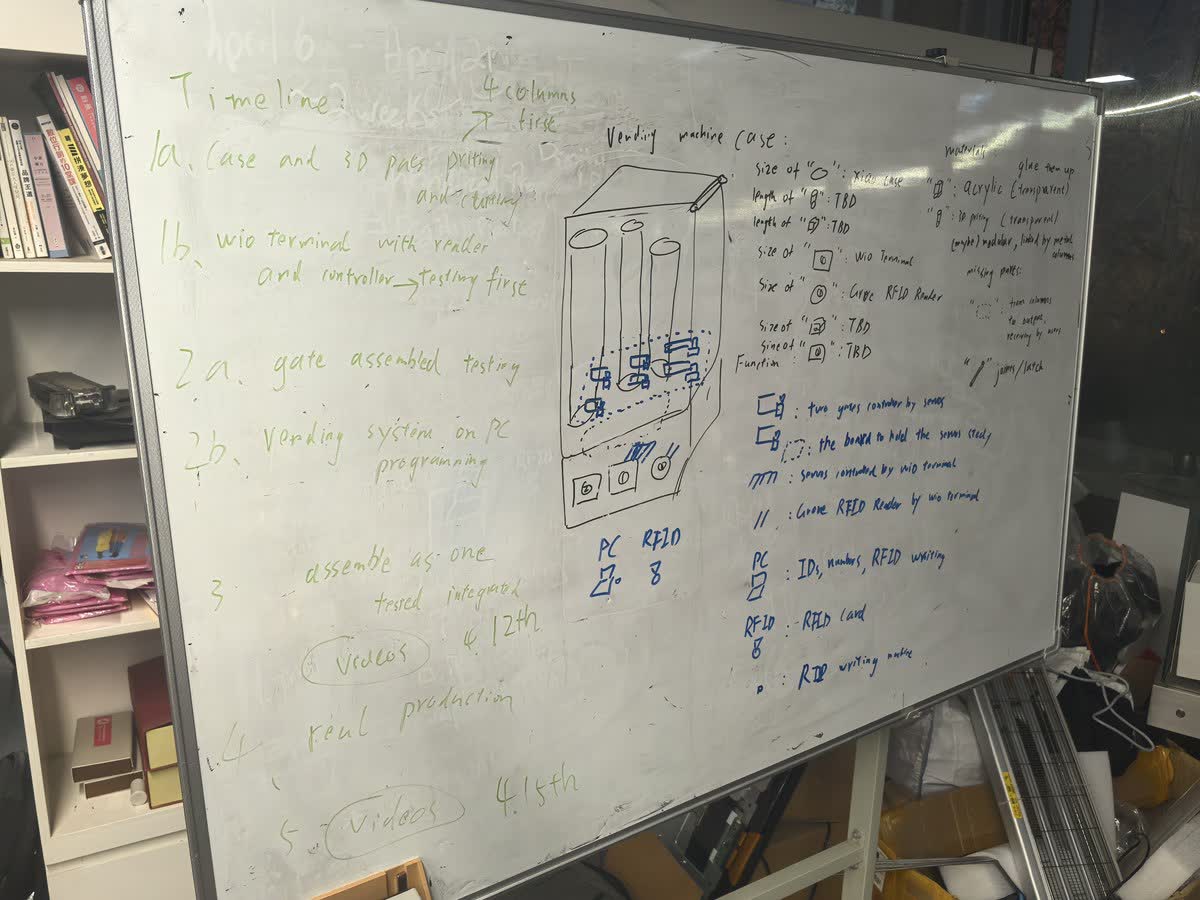
Timeline
| Phase | Task | Target |
|---|---|---|
| 1a | Case and 3D parts cutting and printing | Week 12 |
| 1b | Wio Terminal with reader and controller testing | Week 12 |
| 2a | Gate assembly testing | Week 12 |
| 2b | Vending system on PC programming | Week 12 |
| 3 | Assemble as one, test, integrate, record videos | Week 12 |
| 4 | Real production | By the Week 20 |
Vending Machine Architecture
The case design uses a column-based dispensing structure: products are stacked vertically and dispensed from the top to the bottom. The structure is built from:
- Acrylic panels (transparent) for the outer case
- 3D-printed parts (transparent, modular) linked by metal columns
- Metal columns running from the output chute to the user-receiving area
- Joints/latches for assembly and access
System Components
3. Component Selection
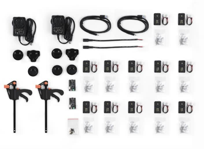
We balanced cost and performance to select each component. All parts are either off-the-shelf Seeed products or affordable serial bus servos.
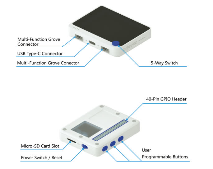
Central Controller: Wio Terminal
The Wio Terminal serves as the brain of the vending machine. It provides a built-in 2.4" LCD screen for status display, Grove connectors for sensor hookup, programmable buttons, and WiFi/BLE for connectivity.
Why Wio Terminal?
- Built-in screen eliminates the need for a separate display module
- Two Grove ports(I2C and UART) allow direct connection to the RFID reader and servo bus
- Compact form factor fits inside the vending machine case
- Programmable buttons can serve as manual overrides
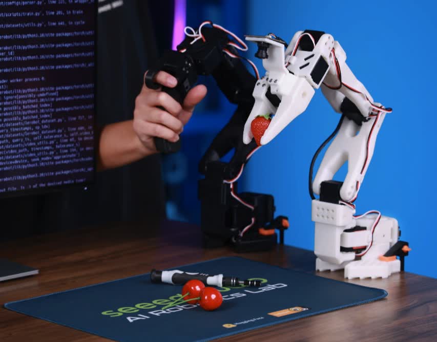
Moving Parts: STS3215 Serial Bus Servo
The STS3215 servo is a serial bus servo that can be daisy-chained on a single communication line. This dramatically simplifies wiring — instead of one signal wire per servo, all servos share one serial bus controlled by the Wio Terminal.
Why STS3215?
- Single-line serial bus control (daisy-chainable)
- Position feedback for precise gate control
- Sufficient torque for the dispensing mechanism
- Affordable compared to traditional smart servos
Output Structure
The dispensing mechanism uses a single-column design: products are loaded from the top and dispensed downward through servo-controlled gates. Each column holds multiple XIAO boards stacked vertically, and a gate at the bottom releases one unit at a time.
Payment: Grove RFID Reader
A Grove-compatible RFID module handles user authentication and payment. It communicates with the Wio Terminal via I2C at 13.56 MHz.
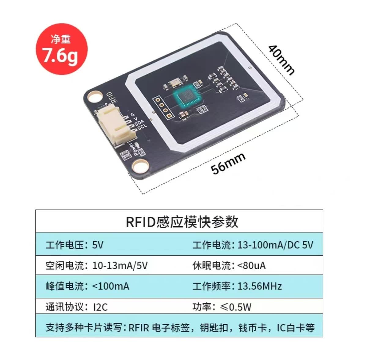
| Spec | Value |
|---|---|
| Operating voltage | 5V |
| Operating current | 13–100 mA |
| Frequency | 13.56 MHz |
| Protocol | I2C |
| Supported cards | RFID tags, key fobs, IC cards |
Workflow:
- A PC-based vending system writes product and credit info to RFID cards
- Users tap the RFID card on the vending machine reader
- The Wio Terminal verifies the card, triggers the servo gate, and dispenses the product
4. Prototype Testing
With all components selected, we built a working prototype and ran three rounds of testing.
Test 1: Wio Terminal + RFID Integration
First integration test connecting the Wio Terminal with the RFID writer. The system successfully reads card data and displays status on the LCD.
Test 2: Servo Movement
Testing the STS3215 servo for gate control. The servo moves to precise positions to open and close the dispensing gate.
Test 3: Structure Assembly
Assembling the physical structure and testing the full mechanical flow — from product loading to dispensing.
5. Integration: Servo + Warehouse Column
With the individual components validated, the next step was integrating the servo mechanism with the warehouse column — the core dispensing unit of the vending machine.
3D-Printed Servo Arm
We designed a custom arm to connect the STS3215 servo to the dispensing gate. The arm was 3D-printed with mounting holes that align with the servo spline and the column latch mechanism.
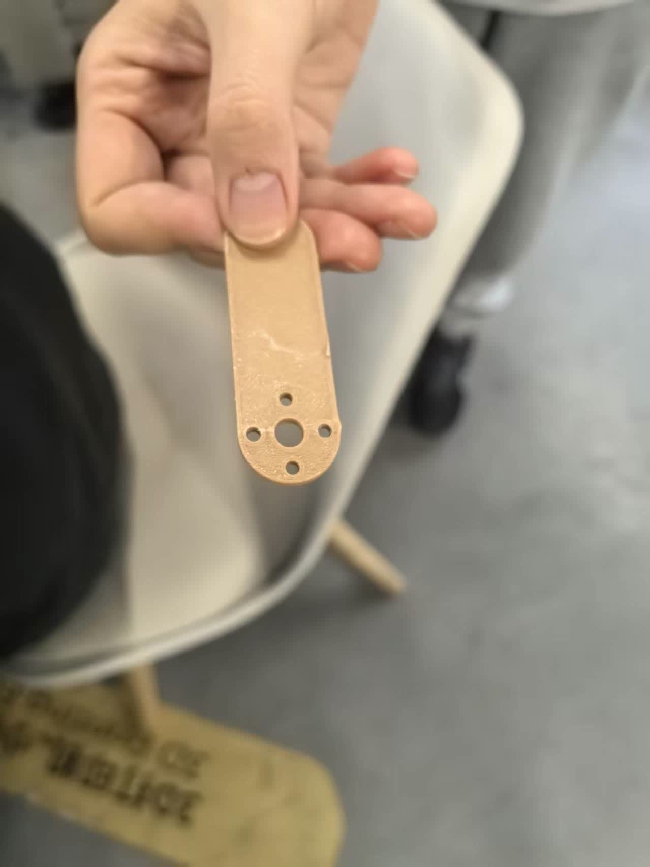
The 3D-printed bar attaches directly to the servo horn. The mounting holes allow it to interface with the column gate, converting rotational motion into a push/pull action that releases one XIAO at a time.
Column Warehouse Assembly
The column warehouse holds XIAO boards stacked vertically. Each column acts as a gravity-fed magazine — when the gate at the bottom opens, the lowest board drops out and the rest slide down.
The assembled warehouse column with boards loaded. The transparent structure lets users see the remaining stock at a glance.
Manual Dispensing Test
Before wiring everything to the Wio Terminal, we tested the mechanism manually — pushing the 3D-printed arm to simulate the servo action and confirming that a single XIAO board is dispensed cleanly each time.
Manually actuating the servo arm to push a XIAO out of the column. This validates the mechanical clearance and confirms the gate-release design works before electronic integration.
RFID + Wio Terminal Testing
After validating the mechanical system, we integrated the RFID module with the Wio Terminal to test card reading functionality.
Testing RFID card interaction on the Wio Terminal. The system reads the card and prepares for triggering the dispensing mechanism.
Full Integration: Servo + RFID + Wio Terminal
In this stage, both the servo system and RFID reader were connected to the Wio Terminal. All wiring was organized and enclosed inside the 3D-printed case for a clean and compact setup.
Full system integration test. The RFID card triggers the Wio Terminal, which controls the servo to simulate the dispensing process.
6. Assemble All Together
With all subsystems tested individually, we proceeded to assemble everything into a complete machine.
Final assembly process. The pin diagram is referenced to ensure correct wiring, and all components are mounted securely inside the structure.
7. Final System Demonstration
System Initialization and Workflow
This video demonstrates the complete system workflow:
- Checking RFID reader, LCD, and servo status
- Pressing Button A on the Wio Terminal to initialize
- Reading RFID card
- Triggering servo to dispense product
The system successfully reads the RFID card and dispenses a XIAO RP2040 board. The servo operates twice to ensure reliable output.
Servo Operation & Output Mechanism
A closer look at the dispensing mechanism from above:
The servo motion (0 → 1024 → 0) controls the gate precisely, allowing one XIAO board to be released per cycle.
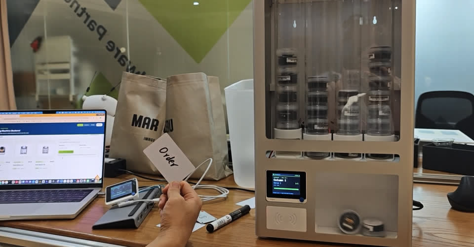
8. Final Result (Hero Shots)
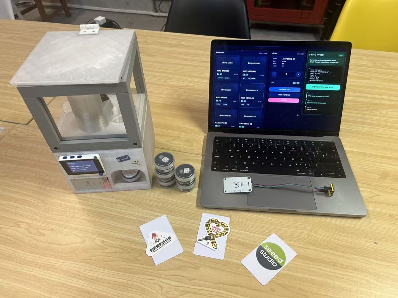
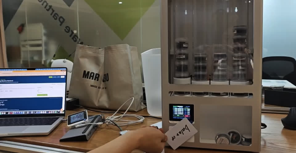
Complete system setup: PC backend, RFID writer, and vending machine with integrated reader and servos.
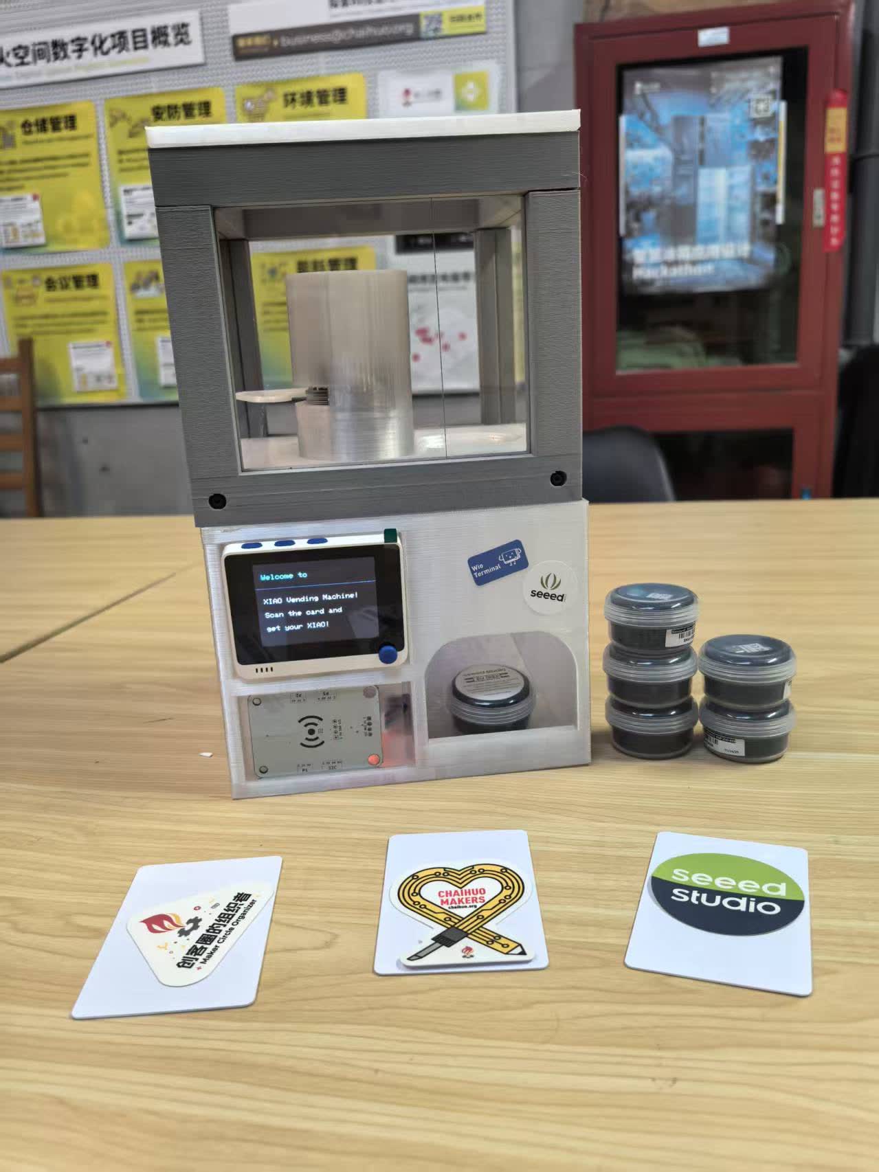
Final vending machine prototype.
9. From Prototype to Full System — How to Vend Almost Anything
The Week 12 prototype proved the card → reader → servo → dispense loop. After the Fab Academy machine week, we turned that loop into a fully functional four-column machine with a live PC backend, RFID writer, inventory tracking, and two real dispense modes. The open-source package is published as:
Seeed-Studio/how-to-vend-almost-anything
That repository is not only a finished XIAO vending machine — it is the reference system for a bigger idea: using fab practices to design local systems that can vend almost anything (any product family that shares one shape and rides a modular column + bus-servo architecture).
| Layer | What it is |
|---|---|
| This Week 12 page | The Fab Academy prototype — ideation, BOM, bring-up, first working dispense |
| how-to-vend-almost-anything | The full reference machine — backend dashboard, dual Wio firmware, 4 columns, documented assembly |
9.1 Operator backend dashboard
A Node.js backend on a laptop serves a three-page operator UI at http://localhost:3000: Config, Inventory, and Operate. Two Wio Terminals talk to it over WiFi — one as the machine reader (frontend), one as the RFID card writer (backend).
Config — flash each Wio Terminal
The Config page detects this computer’s LAN IP, flags a network mismatch if a Wio still points at an old address, saves WiFi + backend URL into the sketch, and flashes firmware over USB via arduino-cli.
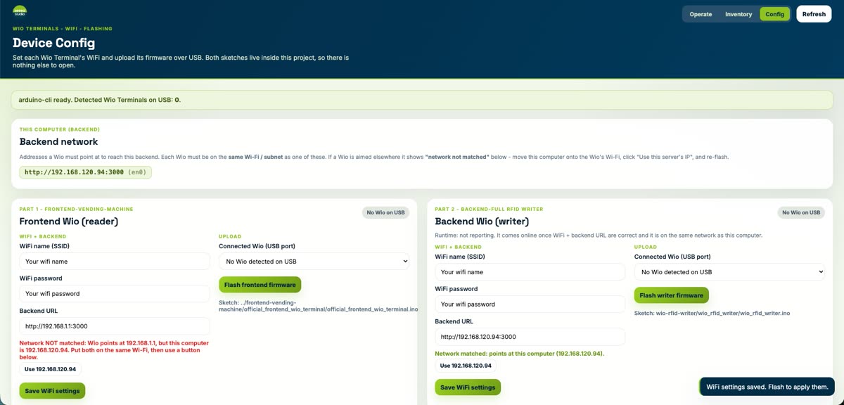
Config: Backend Network URL, Frontend Wio (reader) WiFi/flash, Backend Wio (writer) WiFi/flash.
Inventory — load the four columns
Each column is tracked as stock vs capacity (26 cm column / 2.2 cm product → max 10 units). Operators set counts, refill, and see empty / needs-refill badges plus an inventory log.
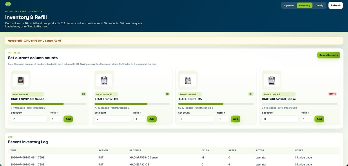
Inventory: A1–A4 map to four bus servos (ESP32-S3 Sense, ESP32-C3, ESP32-C5, nRF52840 Sense).
Operate — write cards and watch stock
On Operate, the operator queues either a direct order card or a selecting balance card. Live metrics show units loaded, refill needs, card balance, and pending writes. Recent orders, balance cards, and the RFID writer queue are logged below.
Operate: set quantities per product, create the order, and queue the card for the Wio writer.
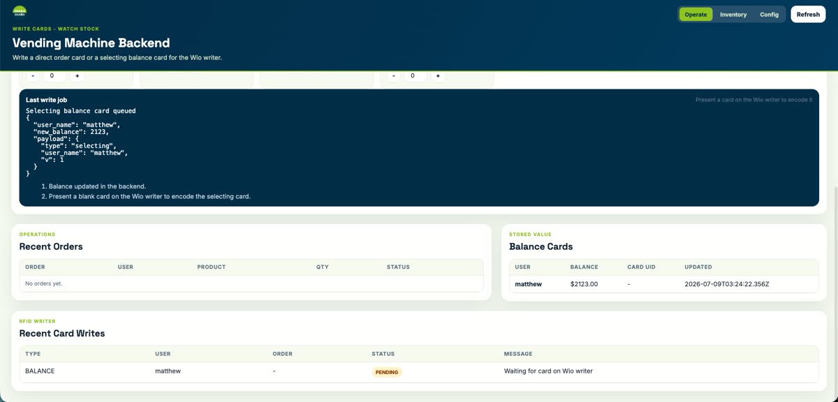
Last write job + logs: recent orders, stored-value balance cards, and pending RFID writes.
9.2 Two real dispense modes
The full machine supports two card types. Both start on the PC (write the card on the backend Wio), then the customer walks to the machine and taps the frontend reader. Real-operation videos for both modes are at the top of this page.
| Mode | Card | What happens at the machine |
|---|---|---|
| Direct order | Pre-paid SKU + quantity encoded on the card | Tap → machine dispenses exactly that order (no on-machine selection) |
| Selecting balance | Stored value / balance on the card | Tap → machine shows the column menu on the LCD; customer picks which product to take; balance updates in the backend |
Direct order dispense
Direct order: tap the Order card → Wio shows the column / serve status → servo gate releases the product into the chute.
Selecting balance dispense
Selecting balance: tap the Balance card → LCD shows the four-column menu → customer selects → dispense + backend balance update.
9.3 End-to-end flow (full system)
- Start the backend (
bash xiao-vending-machine-full-code-system/scripts/start_backend.sh) and open the dashboard. - On Config, set WiFi + backend URL and flash the frontend reader + backend writer Wios.
- On Inventory, set how many products are loaded in each column (0–10).
- On Operate, create a direct order or a selecting balance card; present a blank card to the writer Wio to encode it.
- Present the card to the machine reader — direct order dispenses immediately; balance mode lets the user pick a column on the LCD.
Reproduce hardware, firmware, and hosting from the repo README: How to Vend Almost Anything.
10. Source Code
All Arduino sketches and supporting libraries used in this project are tracked in the site repository and can be browsed or downloaded directly from GitLab.
Repository Layout
| Folder | Purpose |
|---|---|
code_RFID/ | Standalone RFID reader / writer sketches and the Emakefun_RFID driver |
code_RFID/rfid-main/ | reading_rfid.ino and writing_rfid.ino — read/write a TRUE token to MIFARE block 4 |
code_servo/scservo-main/ | Waveshare SCServo library (SCSCL + SMS/STS) used by every servo sketch |
code_servo/STS3215_change_id/ | One-off sketch to assign IDs (1, 2, …) to each STS3215 on the bus |
code_servo/STS3215_demo_code/ | Minimal demo to verify a single servo on the daisy-chain |
code_servo/STS3215_test_code/ | Multi-servo SyncWritePosEx test used for the gate motion |
test_for_assemble/ | First integrated sketch (test_for_assemble.ino) — RFID + LCD + servo on the Wio Terminal |
vending_machine_final_code/ | Final firmware (vending_machine_final_code.ino) running on the prototype in the videos above |
Final Firmware — vending_machine_final_code.ino
The sketch below is what runs on the Wio Terminal in the demo video. It reads MIFARE block 4 over I2C (Grove Wire1), checks for the literal string TRUE, and on a match runs two HOME → TRIGGER → HOME cycles on both servos via SMS_STS::SyncWritePosEx. All status is mirrored on the built-in LCD.
#include <Wire.h>
#include <TFT_eSPI.h>
#include "Emakefun_RFID.h"
#include "SCServo.h"

TFT_eSPI tft;

#define RFID_ADDR 0x28
MFRC522 mfrc522(RFID_ADDR);
bool rfidReady = false;

#define SERVO_NUM 2
SMS_STS st;

byte ID[SERVO_NUM]    = {1, 2};
u16  Speed[SERVO_NUM] = {1500, 1500};
byte ACC[SERVO_NUM]   = {50, 50};
s16  Pos[SERVO_NUM]   = {1024, 1024};

const s16 HOME_POS    = 1024;
const s16 TRIGGER_POS = 0;
const byte DISPENSE_CYCLES = 2;
const unsigned long DISPENSE_FORWARD_DELAY_MS = 1800;
const unsigned long DISPENSE_RETURN_DELAY_MS  = 1200;

void moveBothTo(s16 target) {
  for (int i = 0; i < SERVO_NUM; i++) Pos[i] = target;
  st.SyncWritePosEx(ID, SERVO_NUM, Pos, Speed, ACC);
}

void runDispenseCycles(byte cycles) {
  for (byte cycle = 0; cycle < cycles; cycle++) {
    moveBothTo(TRIGGER_POS);
    delay(DISPENSE_FORWARD_DELAY_MS);
    moveBothTo(HOME_POS);
    delay(DISPENSE_RETURN_DELAY_MS);
  }
}

void loop() {
  if (!rfidReady) {
    if (digitalRead(WIO_KEY_A) == LOW) { initRFID(); delay(500); }
    return;
  }
  if (!mfrc522.PICC_IsNewCardPresent()) return;
  if (!mfrc522.PICC_ReadCardSerial()) return;

  MFRC522::MIFARE_Key key;
  for (byte i = 0; i < 6; i++) key.keyByte[i] = 0xFF;

  byte status = mfrc522.PCD_Authenticate(
    MFRC522::PICC_CMD_MF_AUTH_KEY_A, 7, &key, &(mfrc522.uid));
  if (status != MFRC522::STATUS_OK) { stopRFID(); return; }

  byte buffer[18]; byte size = sizeof(buffer);
  if (mfrc522.MIFARE_Read(4, buffer, &size) == MFRC522::STATUS_OK) {
    bool matched = (buffer[0] == 'T' && buffer[1] == 'R' &&
                    buffer[2] == 'U' && buffer[3] == 'E');
    if (matched) runDispenseCycles(DISPENSE_CYCLES);
  }
  stopRFID();
}
Truncated for readability — the full sketch (with LCD helpers, RFID init, error screens) is in
vending_machine_final_code/vending_machine_final_code.ino.
How to Reproduce
- Install the Arduino IDE and add the Wio Terminal board package.
- Copy the
SCServolibrary fromcode_servo/scservo-main/and theEmakefun_RFIDdriver fromcode_RFID/into your Arduinolibraries/folder. - Use
code_servo/STS3215_change_id/to assign IDs1and2to your two STS3215 servos (one at a time). - Use
code_RFID/rfid-main/writing_rfid.inoto write theTRUEtoken to MIFARE block 4 of your card. - Flash
vending_machine_final_code/vending_machine_final_code.inoto the Wio Terminal, press Button A to init the RFID reader, and tap the card.