Week 7
Computer Controlled Machining
This week, I am learning about computer-controlled machining. As part of this, Dr. Sujit and I visited Vigyan Ashram in Pabal, where our mentor, Suhas Sir, provided guidance on operating the CNC router machine. He also emphasized the importance of adhering to safety precautions while working with the machine.
Objectives of the Study
The objective of this assignment is to develop proficiency in computer-controlled machining by engaging in both group and individual tasks.
Group Assignment
1. Complete the lab's safety training to ensure a secure working environment.
2. Conduct a test run to evaluate critical machine parameters, including runout, alignment, fixturing, speeds, feeds, material properties, and toolpaths.
The group assignment is linked here
Individual Assignment
1. Design, mill, and assemble a large (~meter-scale) structure using CNC machining techniques.
2. For extra credit, construct the assembly without using fasteners or glue.
3. Further enhance the design by incorporating curved surfaces as an advanced machining challenge.
For my individual assignment, I have selected a display stand. I will be using SolidWorks for modeling the design.
Solid Works
First, I selected the front plane to create a rough geometric design of the display stand. My display stand consists of three main parts.
1. Back Panel – The vertical board that serves as the main structural support for the stand.
2. Shelves – Horizontal platforms where items can be placed; three shelves.
3. Legs/Base Supports – Two interlocking supports at the bottom that provide stability to the stand.
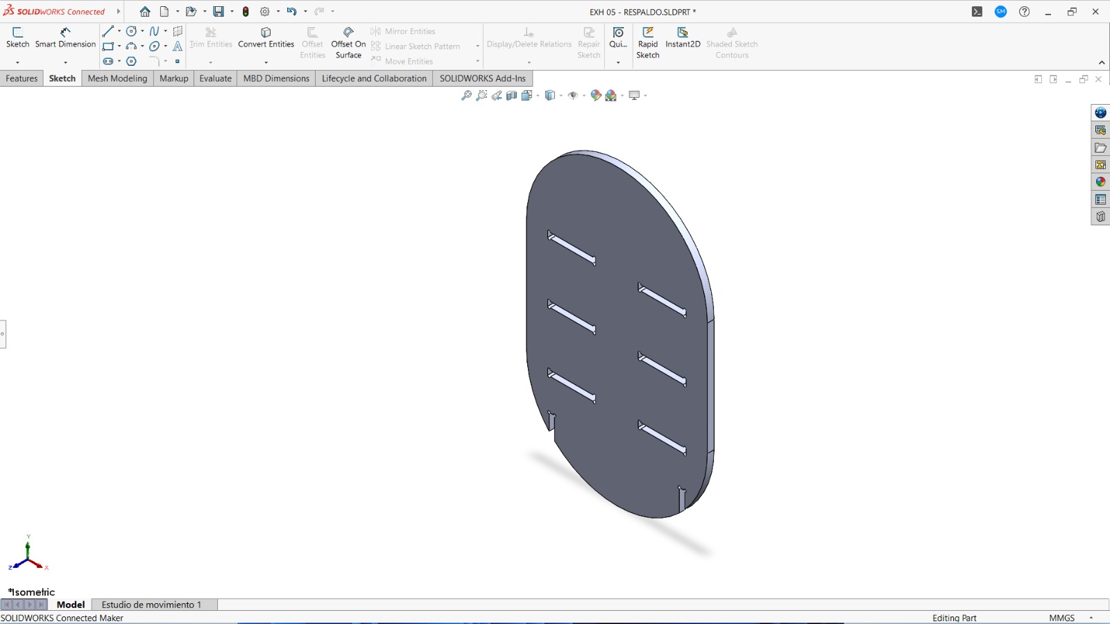
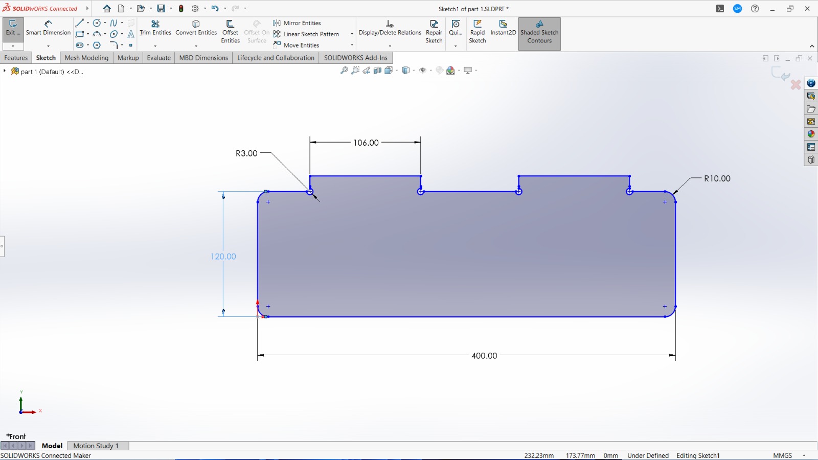
1. Back Panel
First, I created the back panel of the display stand with dimensions of 400 × 650 mm. To achieve this, I initially drew a 400 × 250 mm rectangle using the Rectangle command. Then, I selected the center points of both 400 mm sides and drew circles using the Circle command. Finally, I used the Trim command to remove unwanted lines, shaping the panel as shown in the figure.
For my design, I have selected a 12 mm thick plywood sheet as the material. In the next step, I created slots to fit the shelves. The slot dimensions are 100 × 12 mm.
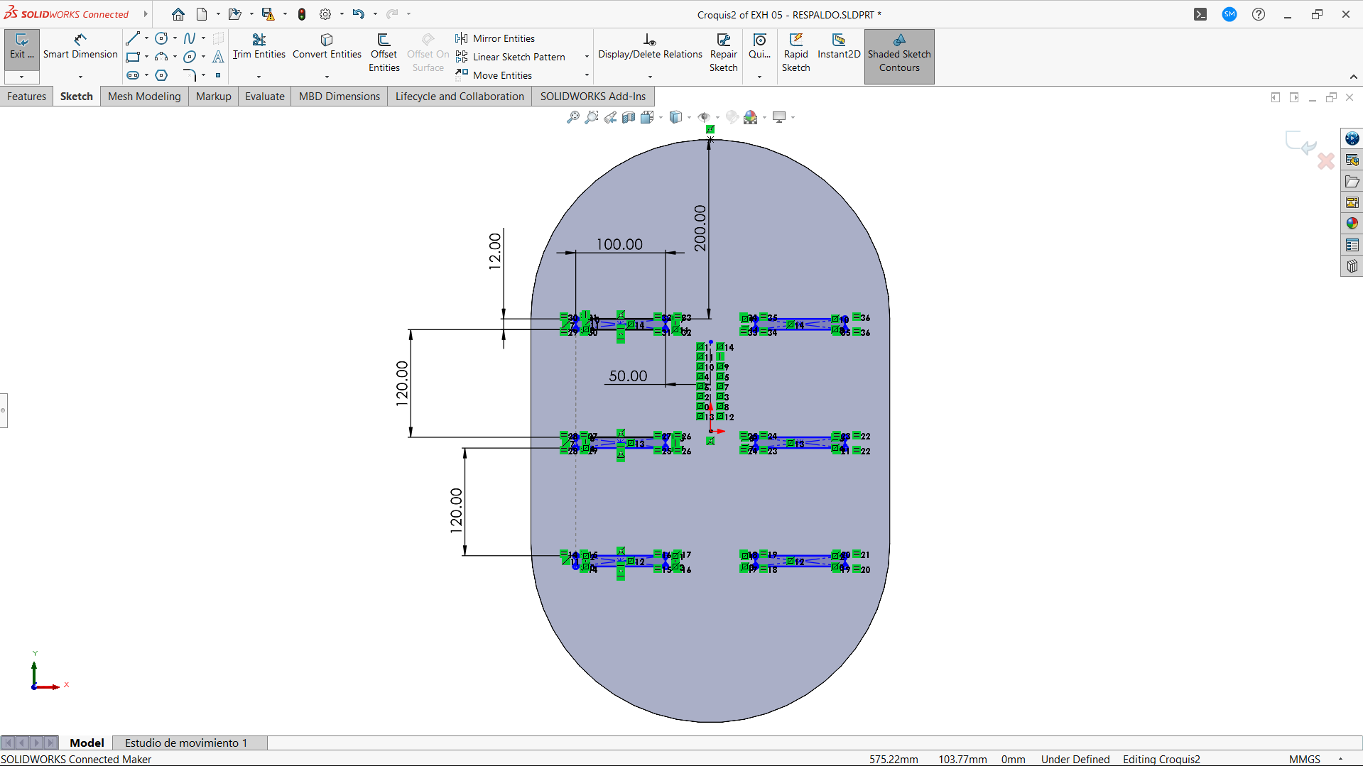
Since the display stand consists of three shelves, I positioned the first slot at the center height of the back panel. The slot is placed 50 mm from the center of the width. To create the slot, I used the Rectangle command to draw a 100 × 12 mm cutout.
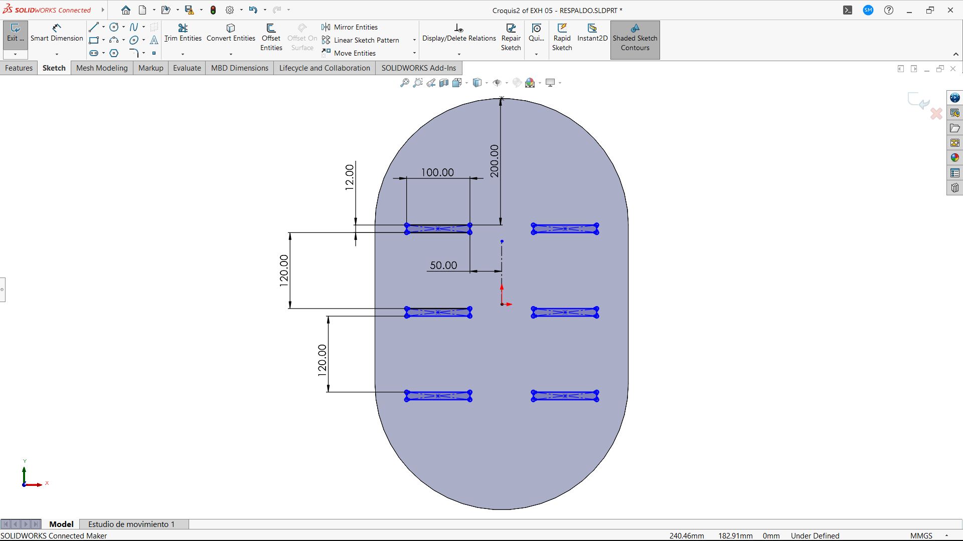
Next, I created additional slots 120 mm above and below the center slot, maintaining the same 100 × 12 mm dimensions. After positioning these slots, I used the Mirror command to replicate the three slots symmetrically on the other side of the back panel.
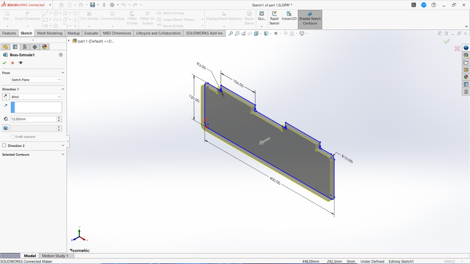
Next, I will draw the slot for the leg/base support fitting. Based on my dimensions, I will create a 2D diagram.
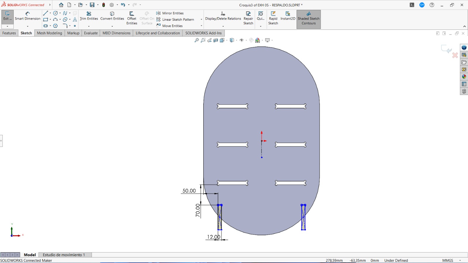
Next, I will exit the sketch and use the Extrude Boss/Base feature, setting the thickness to 12 mm. With this, the back panel will be ready.
2. Shelves
Next, I will begin designing the second part, the shelves. I will create a new part and start a 2D diagram as shown in the figure. These shelves will be interconnected with the back panel that has already been designed.
>
Next, I will exit the sketch and use the Extrude Boss/Base feature, setting the thickness to 12 mm. With this, the Shelves will be ready.
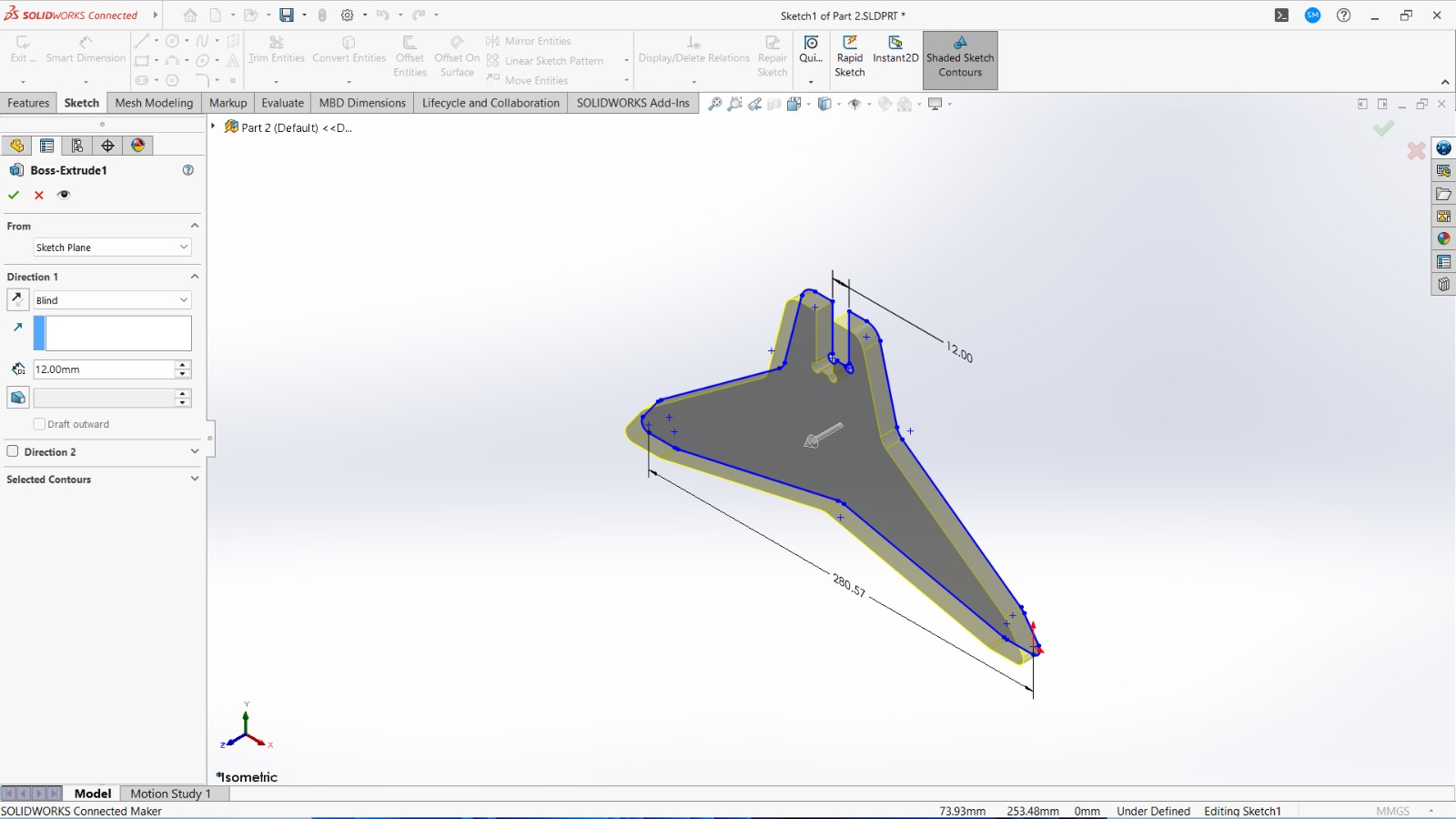
3. Legs/Base Supports
I will begin designing the second part, Legs/Base Supports. Next, I will create a new part and start a 2D diagram as shown in the figure. These Legs/Base Supports will be interconnected with the previously designed back panel.
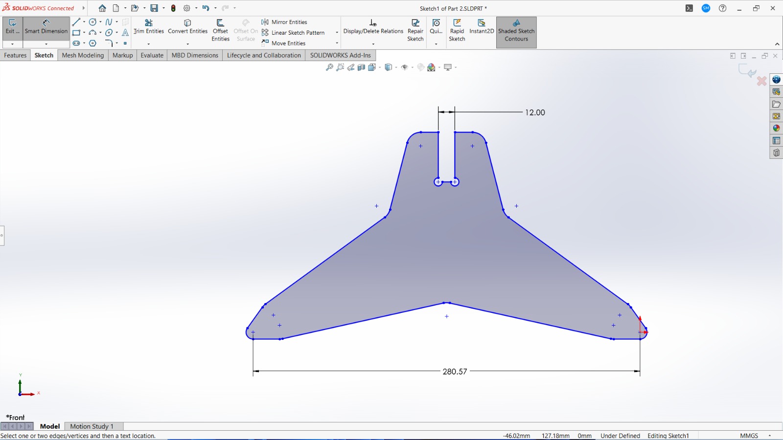
Next, I will exit the sketch and use the Extrude Boss/Base feature, setting the thickness to 12 mm. With this, the Legs/Base Supports will be ready.
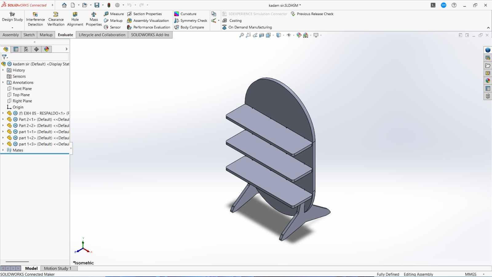
With all three parts ready and saved in SolidWorks, I will proceed to the assembly. I will then fit the shelves and legs/base supports to the back panel. Then assembly is ready then this assembly is saved in .dxf file
Path Ganeration
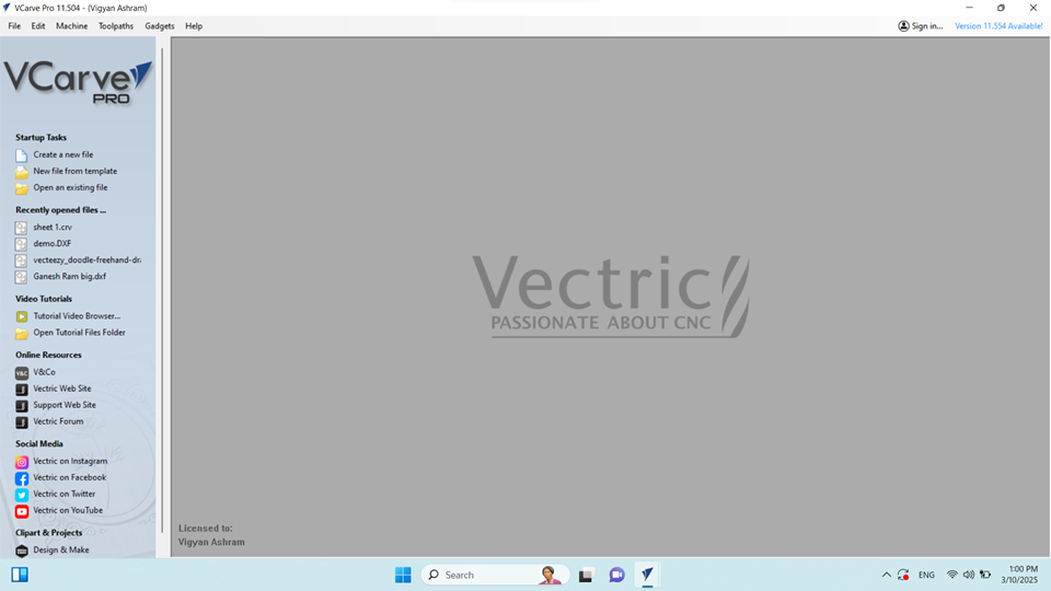
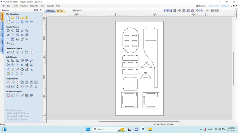
To use the CNC router machine, it is necessary to generate the toolpath. For this purpose, we used VCarve Pro 11.5 software.
When I open the software, the VCarve Pro interface appears. I then navigate to the File menu.
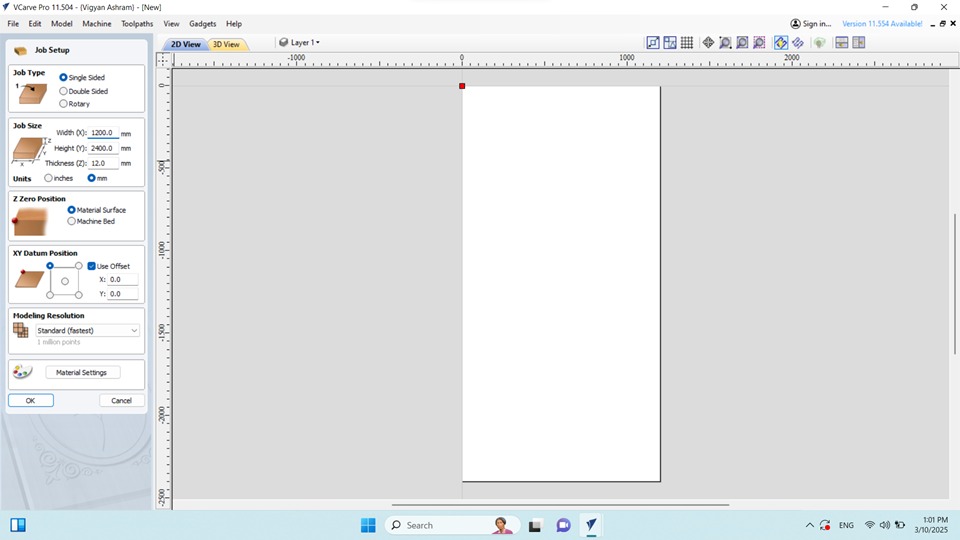
Upon launching the VCarve software, I navigated to the File menu and selected Create New File. In the 2D View, I proceeded to the Job Setup section.
First, I selected the Job Type as Single-Sided. Then, I defined the Job Size with the following dimensions:
Width: 1200mm
Height: 2400mm
Thickness: 12mm
Since I am using a plywood sheet for this job, I set the Z Zero Position to the Material Surface. Next, I specified the XY Datum Position as per the requirements.
After completing the job setup, I clicked OK to proceed.
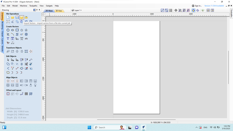
Next, I navigated to the File Operations menu and selected Import Vector to bring in the required design file.
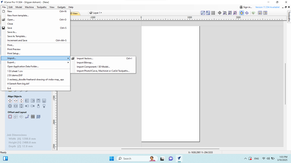
Next, I went to the File menu, selected Import, and then chose Import Component / 3D Model to bring in the necessary 3D design .dxf files.
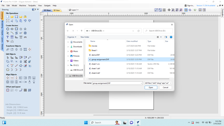
Locate and select the desired .DXF file from the file explorer.
Click Open to import the file into the 2D View.
Next, the imported file is properly arranged on the sheet to ensure optimal placement before generating the toolpath.
>
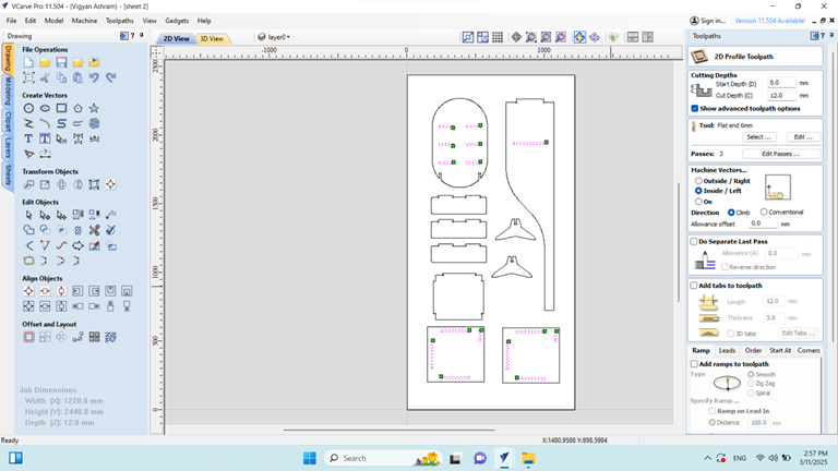
On the right side, navigate to the Toolpath section. Under Machine Vectors, select Inside or Left, then choose all the inner parts and click Calculate to generate the toolpath.
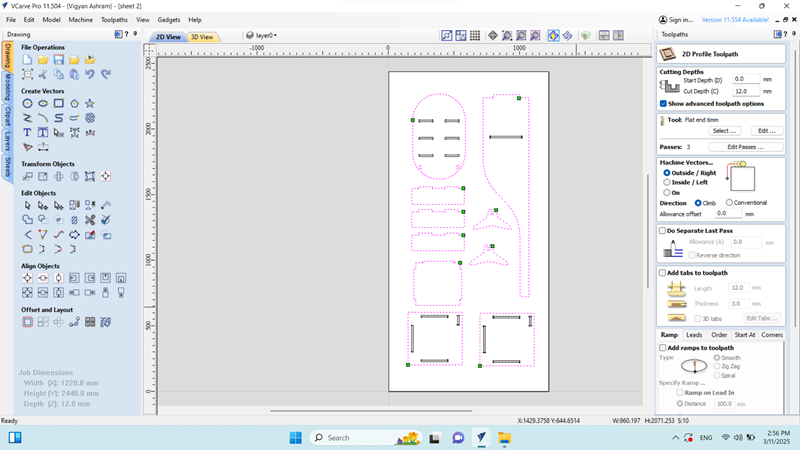
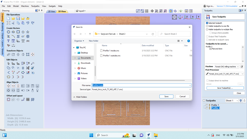
The file is then saved as a .cnc file. The same procedure is repeated for the outside parts by selecting the remaining outer vectors. After making the selection, click Calculate to generate the toolpath. Then click on save toolpath and save it as .cnc files
Then I click on the 3d view to conform.
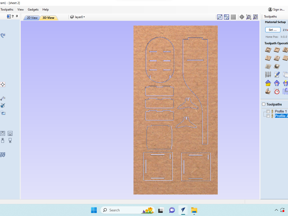
Then, this file is saved as a .cnc file for machining.
CNC Router Machine Operations
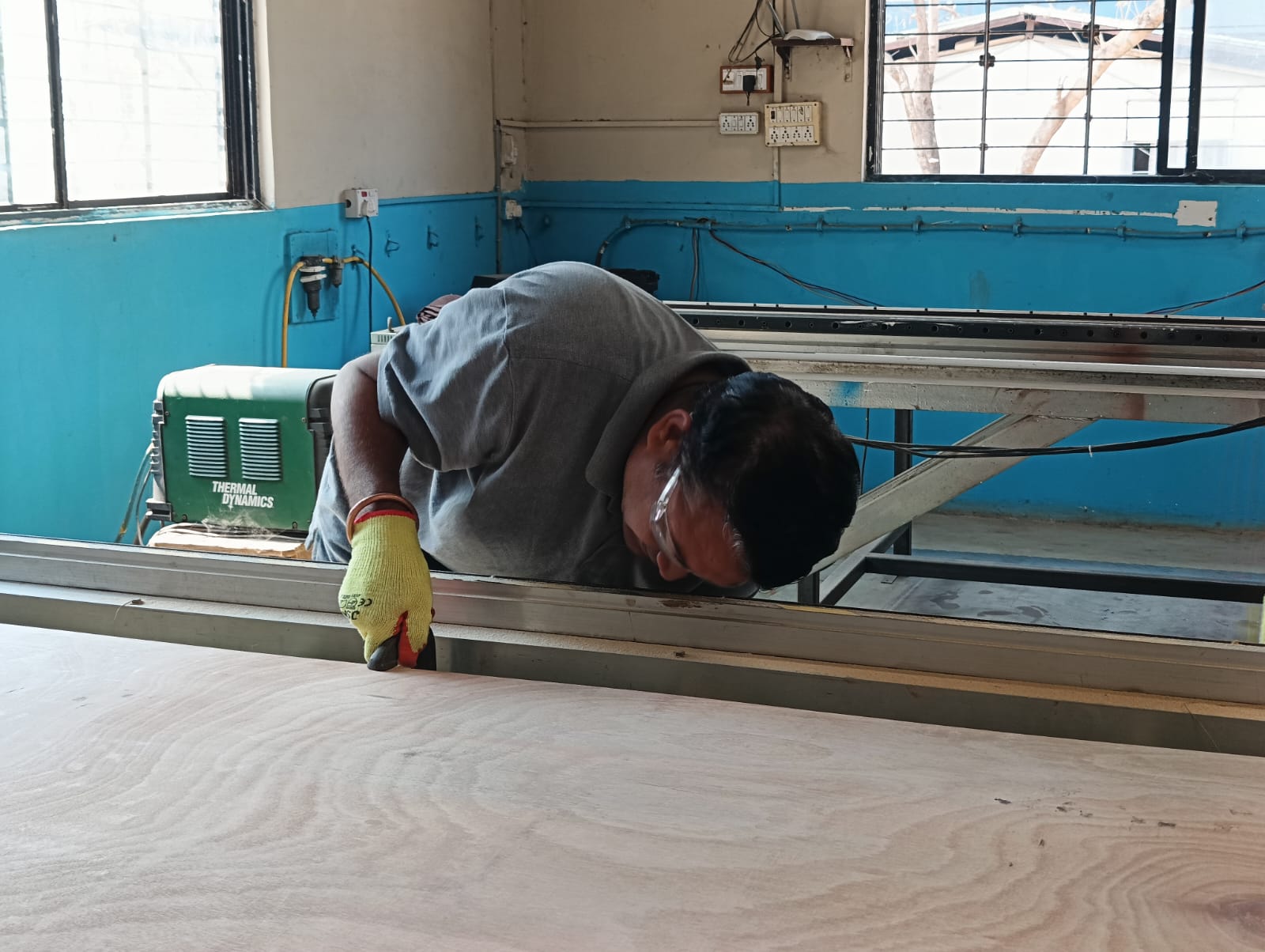
First, place the plywood sheet on the machine bed, ensuring proper alignment. Then, secure it firmly using C-clamps.
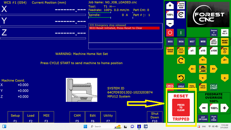
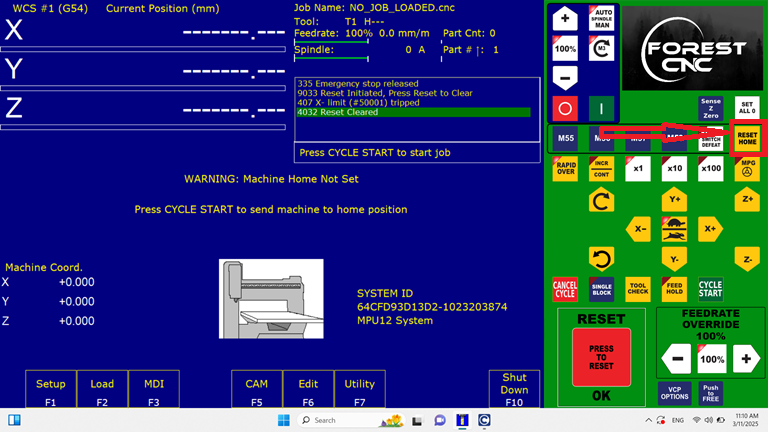
Turn on the machine by pressing the green power button and wait 30 seconds for initialization. Then, open the control software from your desktop. Press the Reset button twice until "Reset Cleared" is displayed.
As reset cleared is displayed on screen.Next, issue the Reset Home command to the machine. After executing this command, the machine will return to its original position.
As the machine returns to its original position, the X, Y, and Z coordinates may change significantly.
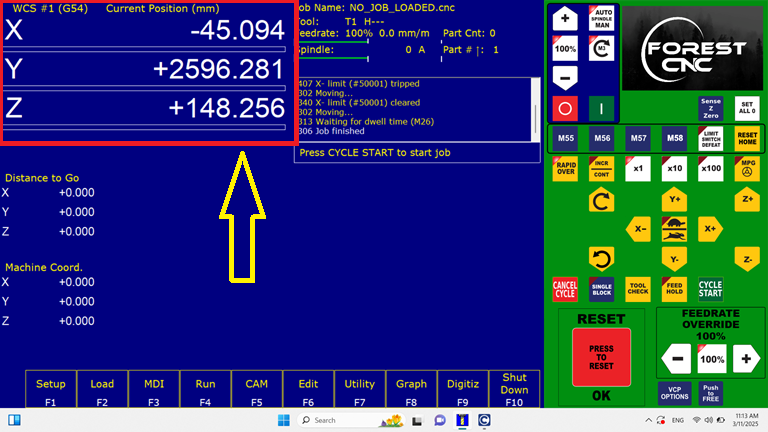
The machine then moves along the X, Y, and Z coordinates to set the origin point for the cutting process.
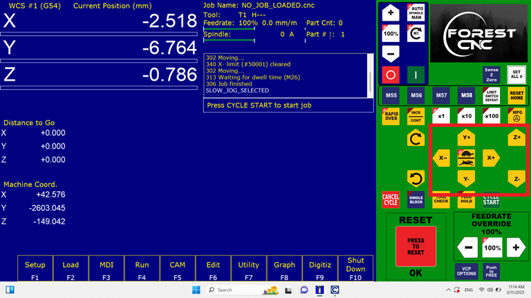
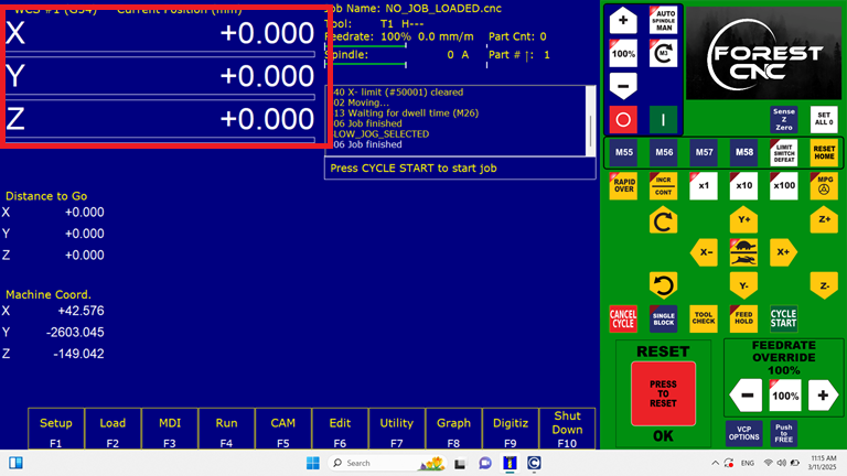
After setting the origin point, reset all X, Y, and Z coordinates to zero.
Once the setup is complete, navigate to the Load menu to import the necessary files.Then, select the required files from the File Explorer.
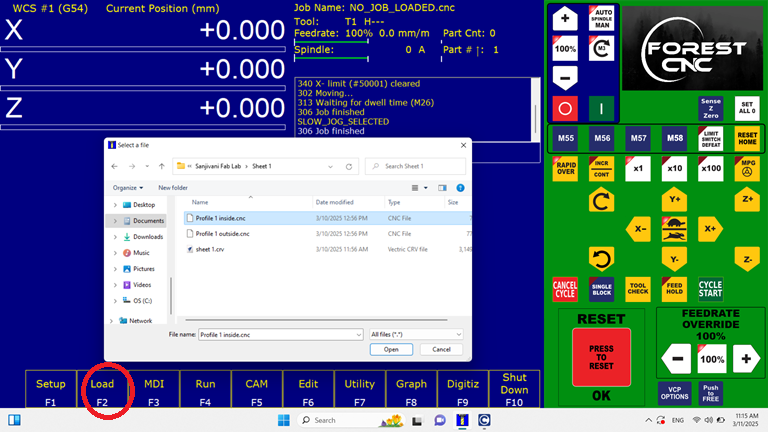
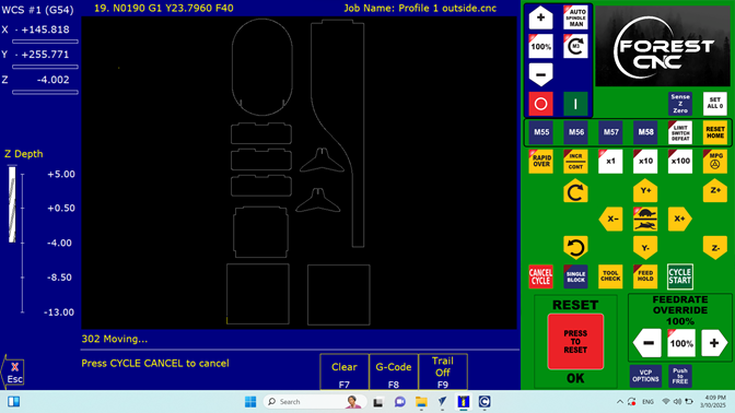
First, I selected the file from the system, then clicked "Open," and the file loaded on the screen
The file displays the toolpath for the inside cut. Then, press "Escape" to proceed.
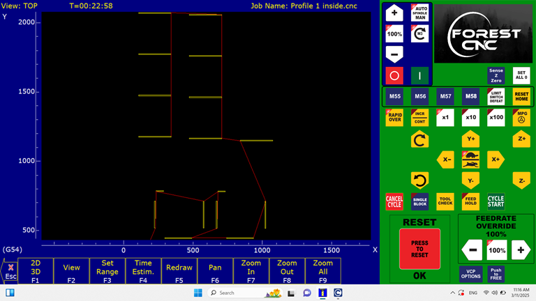
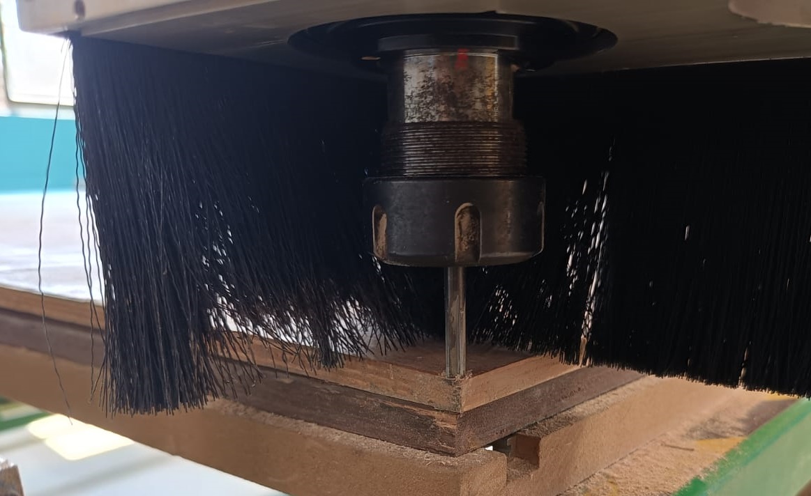
Then, move the spindle in the Z+ direction to a safe height to prevent accidents, as experienced during the group assignment.
Finally, press Start Cycle to begin the operation.
Once the command is given to the CNC router to start the cycle, it begins cutting along the predefined toolpath selected earlier.
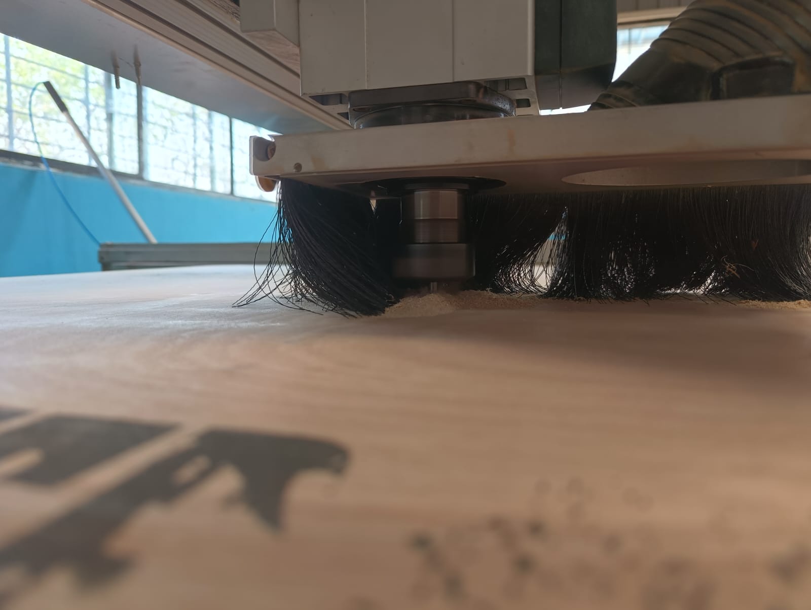
The machine cuts the 12 mm thick plywood in three passes: the first pass at 4 mm, the second at 8 mm, and the final pass at 4 mm. This means that each cutting cycle has a depth of 4 mm. Throughout the process, the cutting path is displayed on the laptop screen in real time.
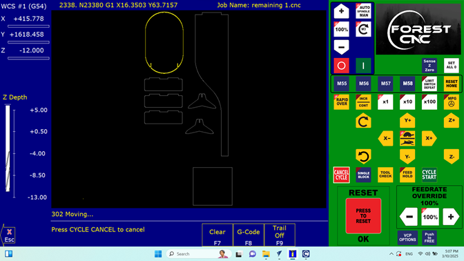
Once the inside cut is completed, move the tool up by pressing "Z+." Using the same origin, select the "Load" command to upload the outside.cnc file for the outside cut.
Then, press "Start Cycle." As the cycle begins, the cutting process will proceed using the same origin, and the cutting path will be displayed on the laptop screen in real time with yellow colour.
Assembling
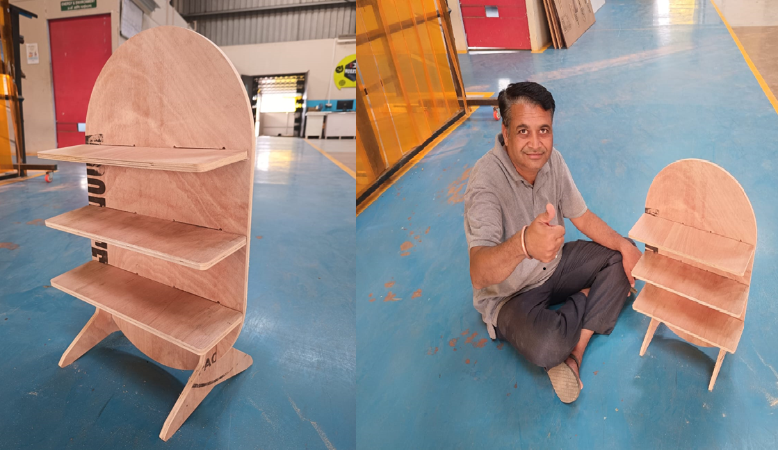
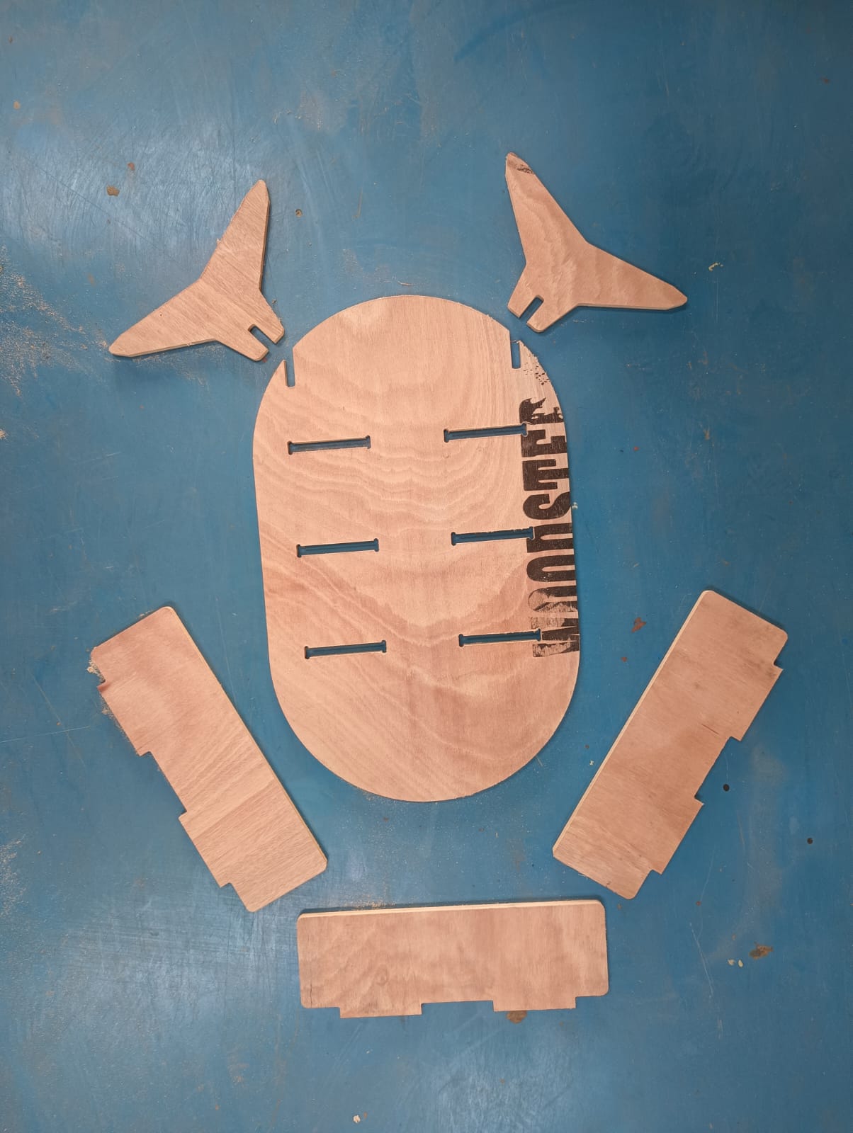
Once the cutting process is completed, all the parts are easily removed from the machine bed. The components are then arranged in an orderly manner, and a photograph is taken for documentation.
After manufacturing all the parts, I began assembling the display stand. First, I fitted the back panel with the base supports to ensure stability. Then, I attached the three shelves to the back panel, securing them in place.
>