Week 14
Interface and Application Programming
In this week, I explored interface and application programming, focusing on how to connect hardware with custom-designed software interfaces to monitor or control embedded systems.
The objective was to create a functional interface that could communicate with a microcontroller to either send commands or display real-time data. I learned the basics of serial communication, event handling, and graphical user interface (GUI) development using tools such as [insert language/tool, e.g., Processing, Python (Tkinter/PySerial), or MIT App Inventor].
As part of the assignment, I developed an application that interfaces with a microcontroller (e.g., XIAO ESP32-C3) to [insert task – e.g., read sensor data, control actuators, or display real-time feedback]. The interface was designed to be user-friendly, providing both functionality and visual feedback.
Through this experience, I gained practical knowledge of:
1. Serial communication protocols (UART)
2. GUI development
3. Real-time data visualization
4. Interaction between software and physical systems
Group Assignment
Individual Assignment
Group Assignment
As part of the group assignment, Dr. Sujit and I conducted a study that included for Interface and Application Programming, we conducted a comparative analysis of various software tools and platforms commonly used for developing user interfaces and interacting with embedded systems. The comparison was based on several criteria, including ease of use, compatibility with microcontrollers, available features, flexibility, and platform support.
The group assignment is linked here
Individual Assignment
As part of the Interface and Application Programming week, I developed a custom mobile application using MIT App Inventor to interface with an input/output device I created.
Application Using MIT App Inventor
This week helped bridge the gap between embedded hardware and user-centric applications, enhancing my ability to develop complete, interactive systems.
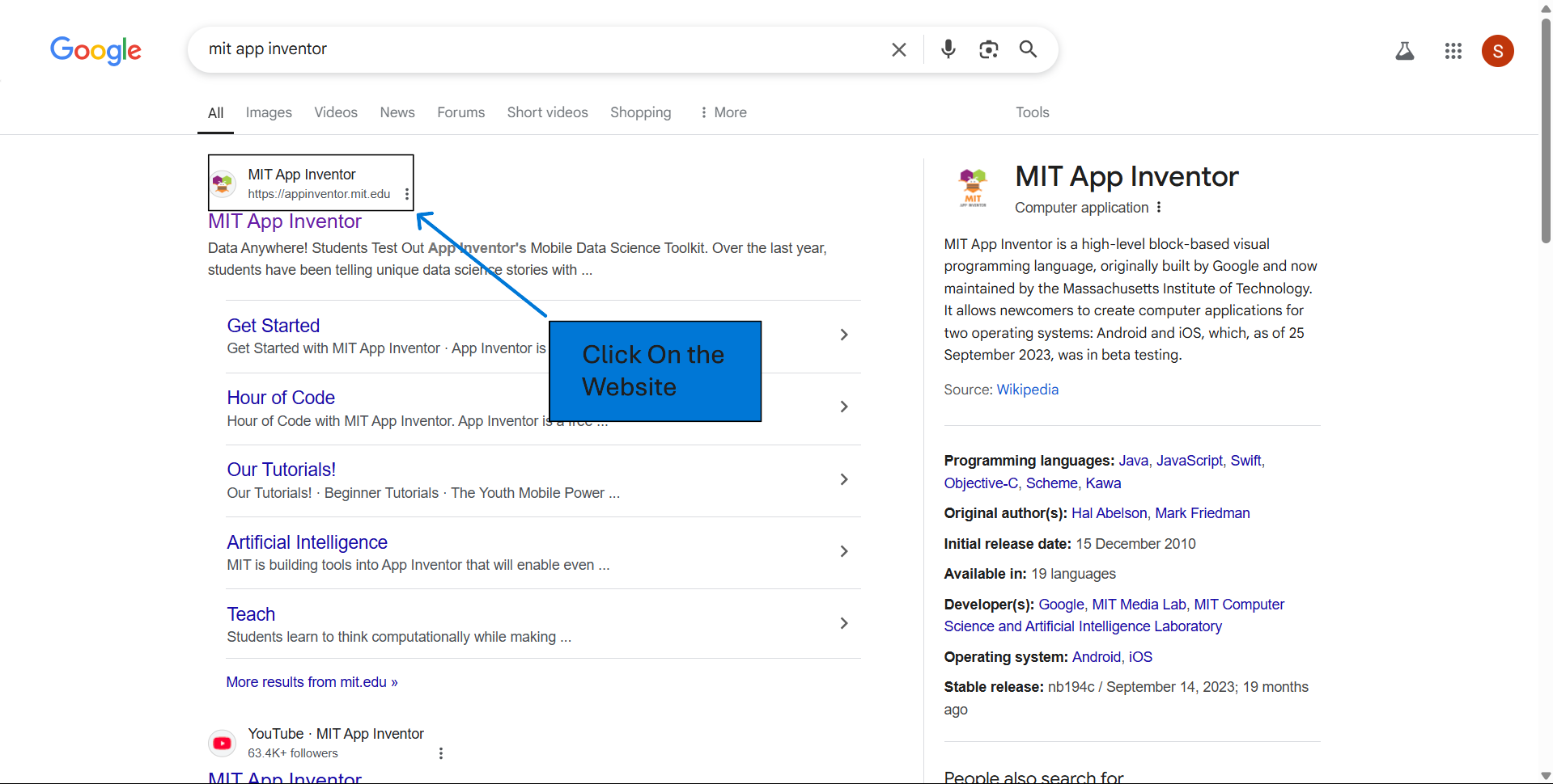
To begin using MIT App Inventor, please visit their official website: https://appinventor.mit.edu/. This platform allows me to create Android applications using a visual, drag-and-drop interface, making it accessible for users with varying levels of programming experience.
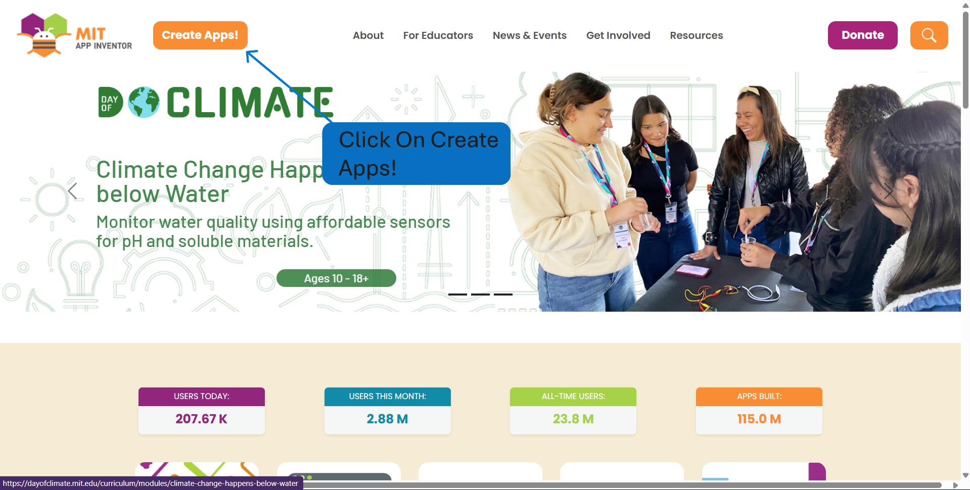
Click on the "Create Apps" button located at the top-right corner of the homepage.
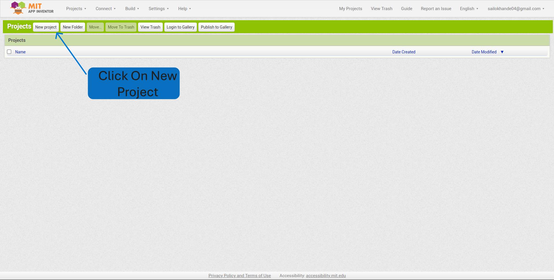
Click on the “Projects” menu. Select “Start new project” from the dropdown.
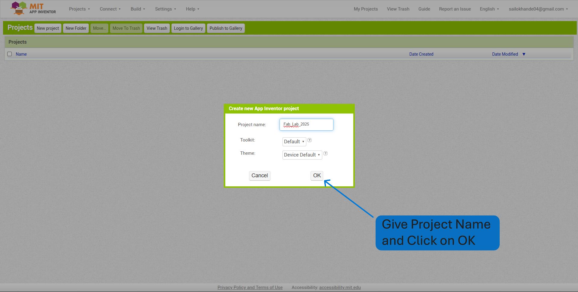
Enter a name for your project make sure the name contains no spaces or special characters and Click OK.
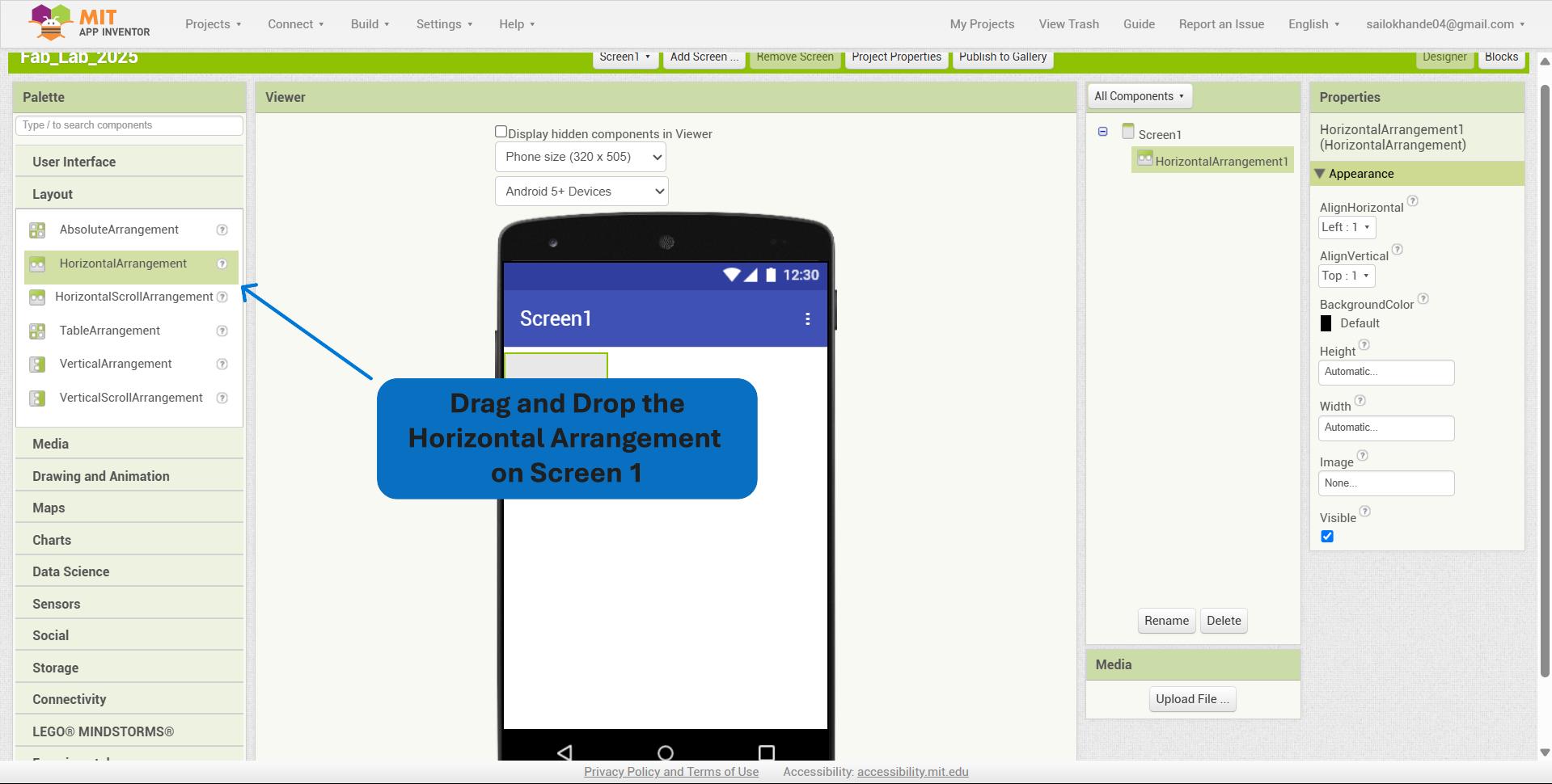
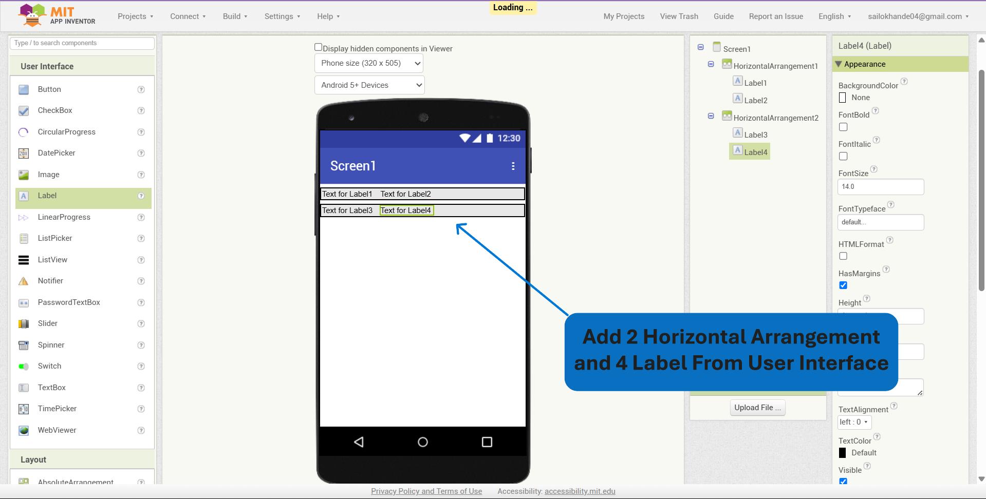
I dragged and dropped a Horizontal Arrangement component onto Screen1 to organize elements horizontally within the user interface.
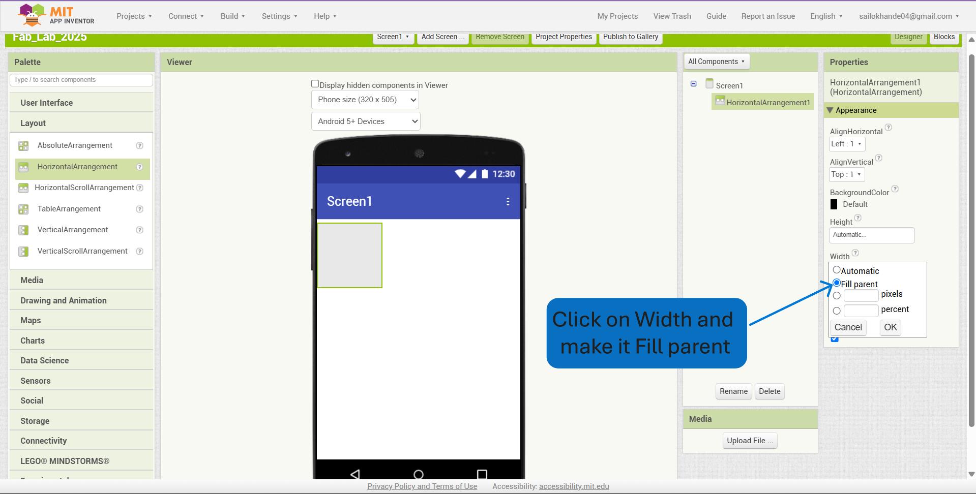
I set the width of the Horizontal Arrangement to "Fill parent" to ensure it occupies the full horizontal space of the screen.
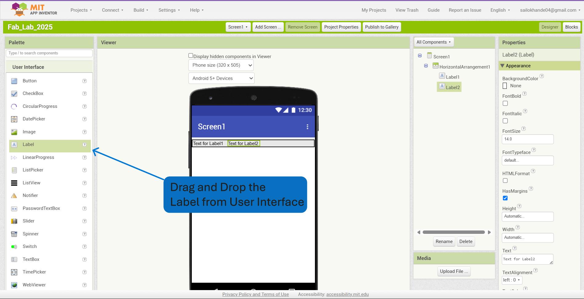
I dragged and dropped a Label component from the User Interface section onto the screen to display text within the application.
I added a total of two Horizontal Arrangement components to structure the layout and placed four Label components within them to display relevant text information in an organized manner.
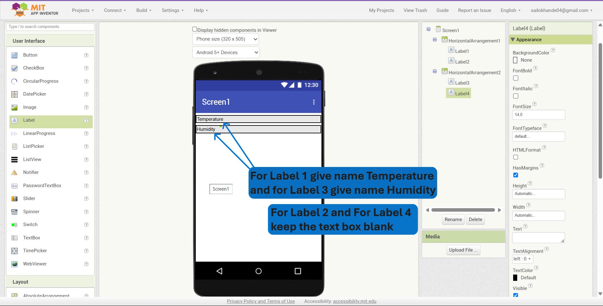
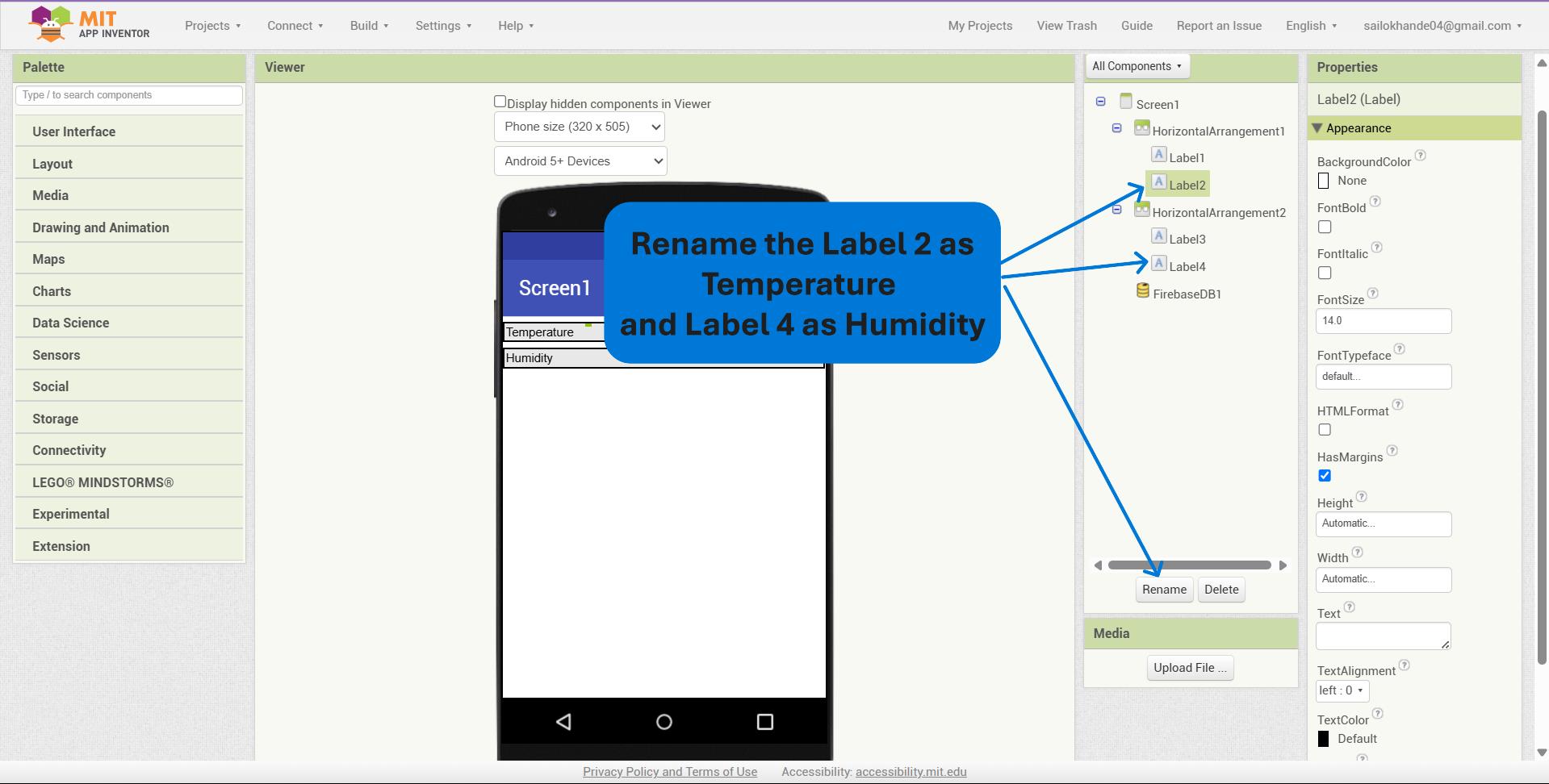
I set the Text properties of two of the Label components to "Temperature" and "Humidity" to clearly indicate the sensor data being displayed in the application.
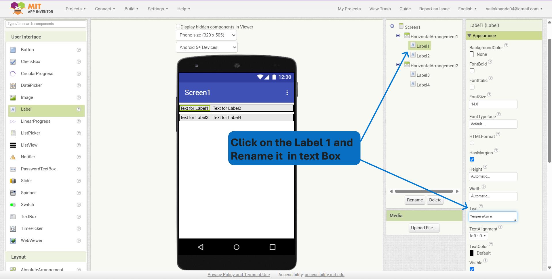
I set the Text property of Label 1 to "Temperature" and Label 2 to (blank) for displaying dynamic temperature values. Similarly, I set Label 3 to "Humidity" and Label 4 to (blank) for displaying dynamic humidity values.
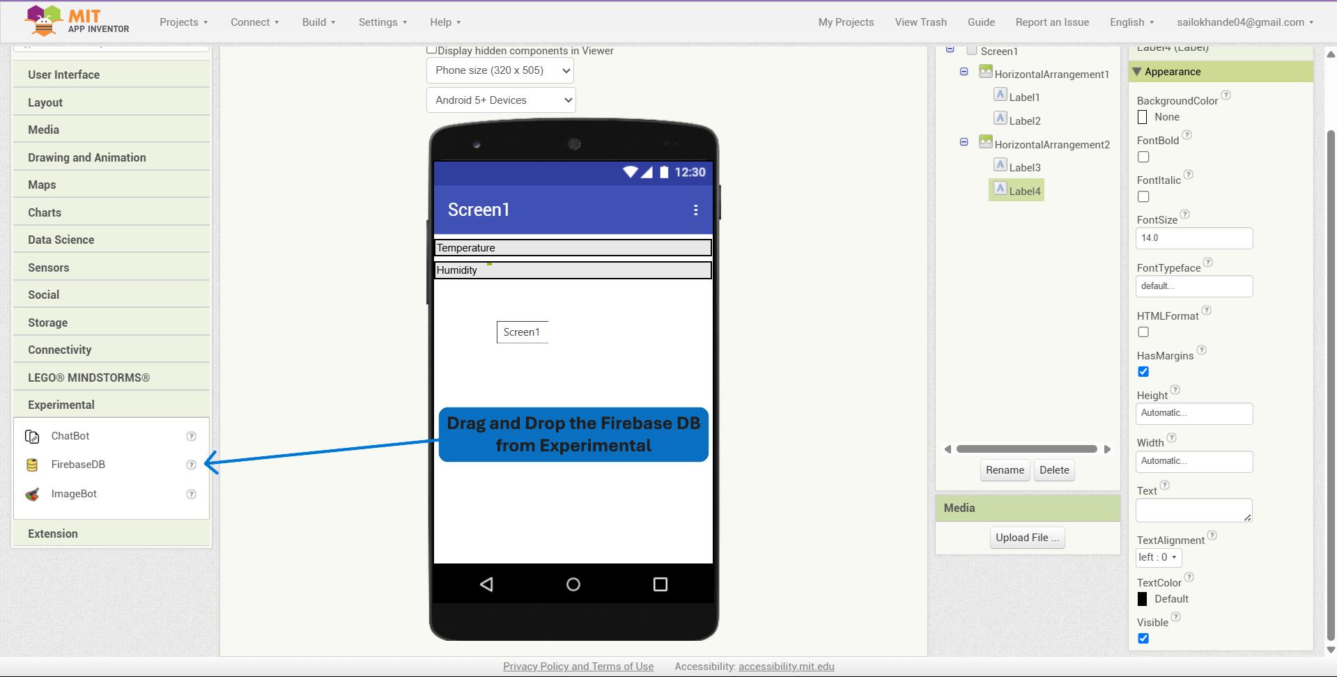
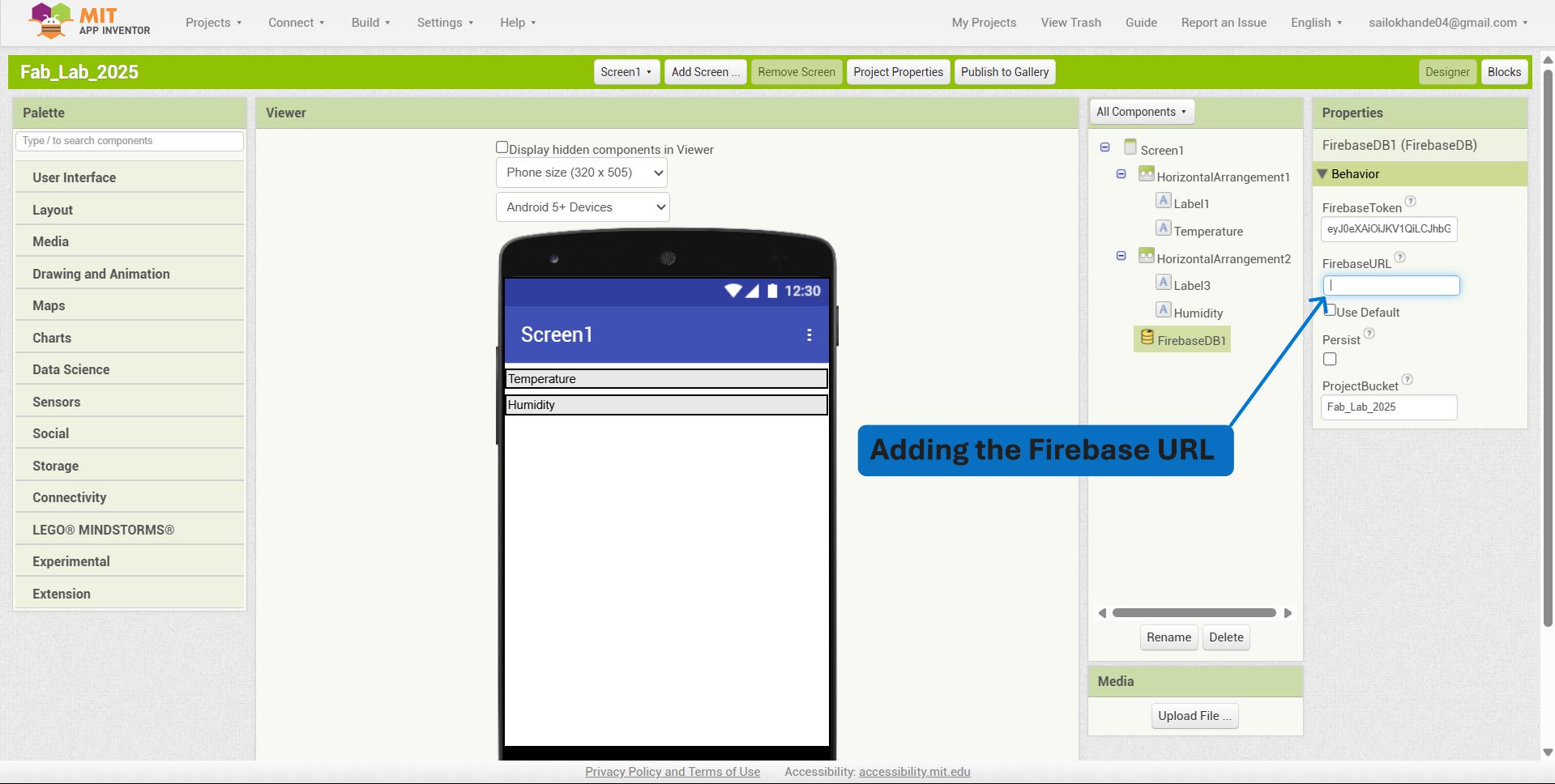
I dragged and dropped the FirebaseDB component from the Experimental section onto the screen to enable real-time database connectivity between the app and Firebase.
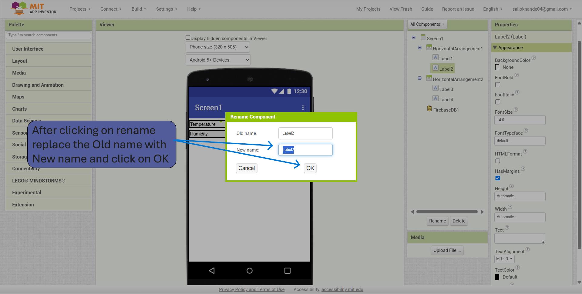
I renamed Label 2 to "TemperatureValue" and Label 4 to "HumidityValue" to clearly indicate that these labels will display the dynamic temperature and humidity readings, respectively.
After clicking on "Rename", I replaced the old name of Label 2 with "TemperatureValue" and the old name of Label 4 with "HumidityValue" to better reflect their intended purpose in displaying sensor data.
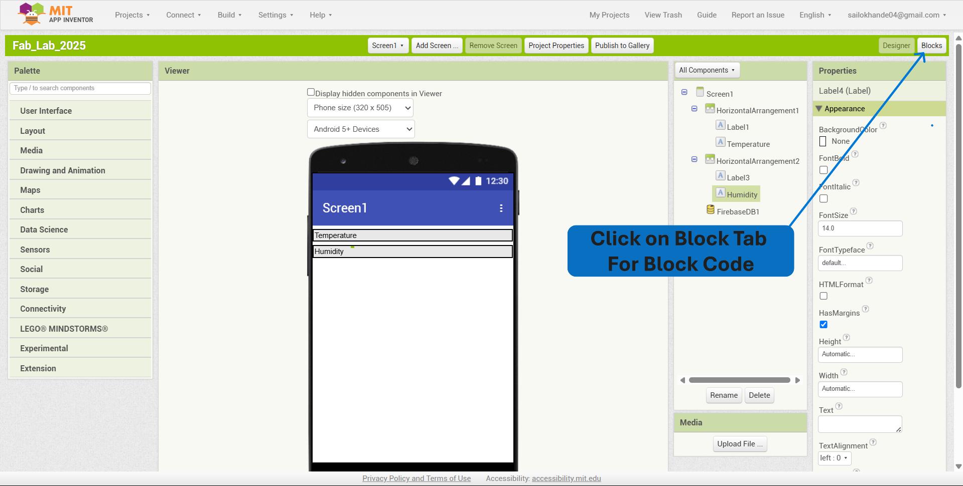
To begin block-based programming, I clicked on the "Blocks" tab in the top-right corner of the MIT App Inventor interface, which opened the visual coding workspace for configuring app logic.
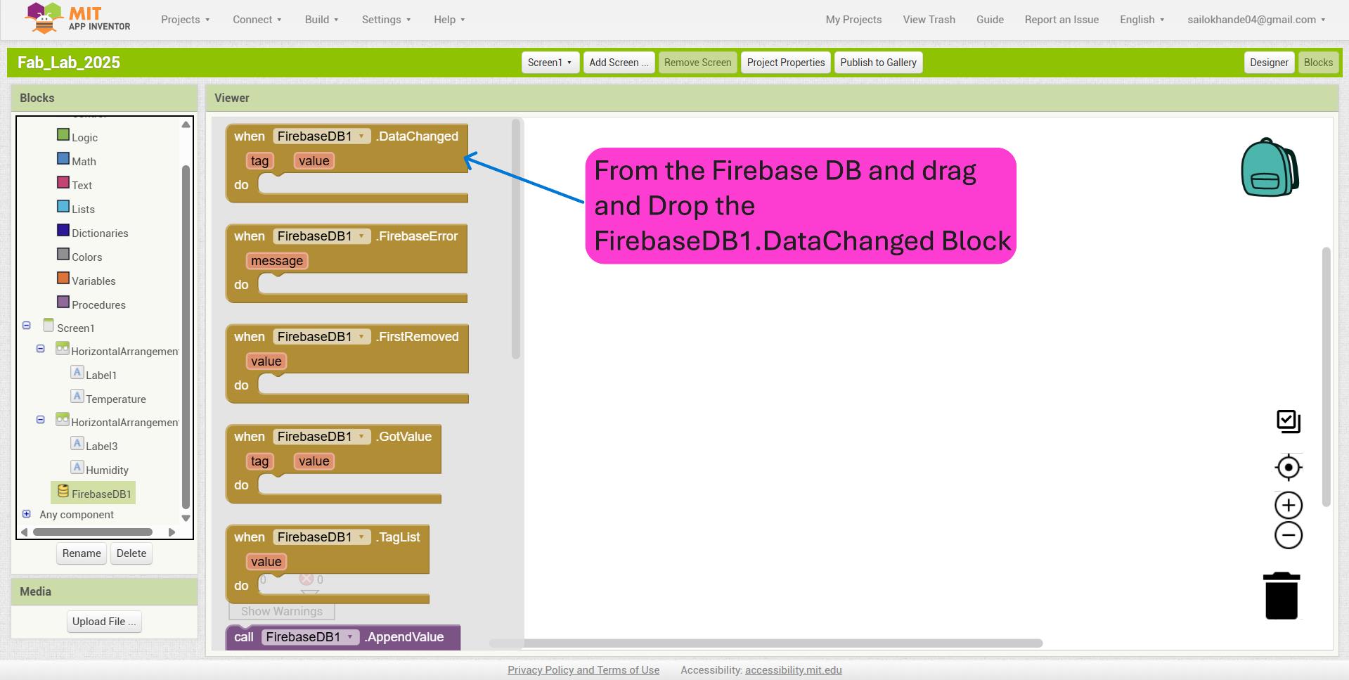
From the FirebaseDB drawer, I dragged and dropped the FirebaseDB1.DataChanged event block into the blocks workspace. This block is triggered whenever data in the Firebase Realtime Database changes, allowing the app to respond to real-time updates.
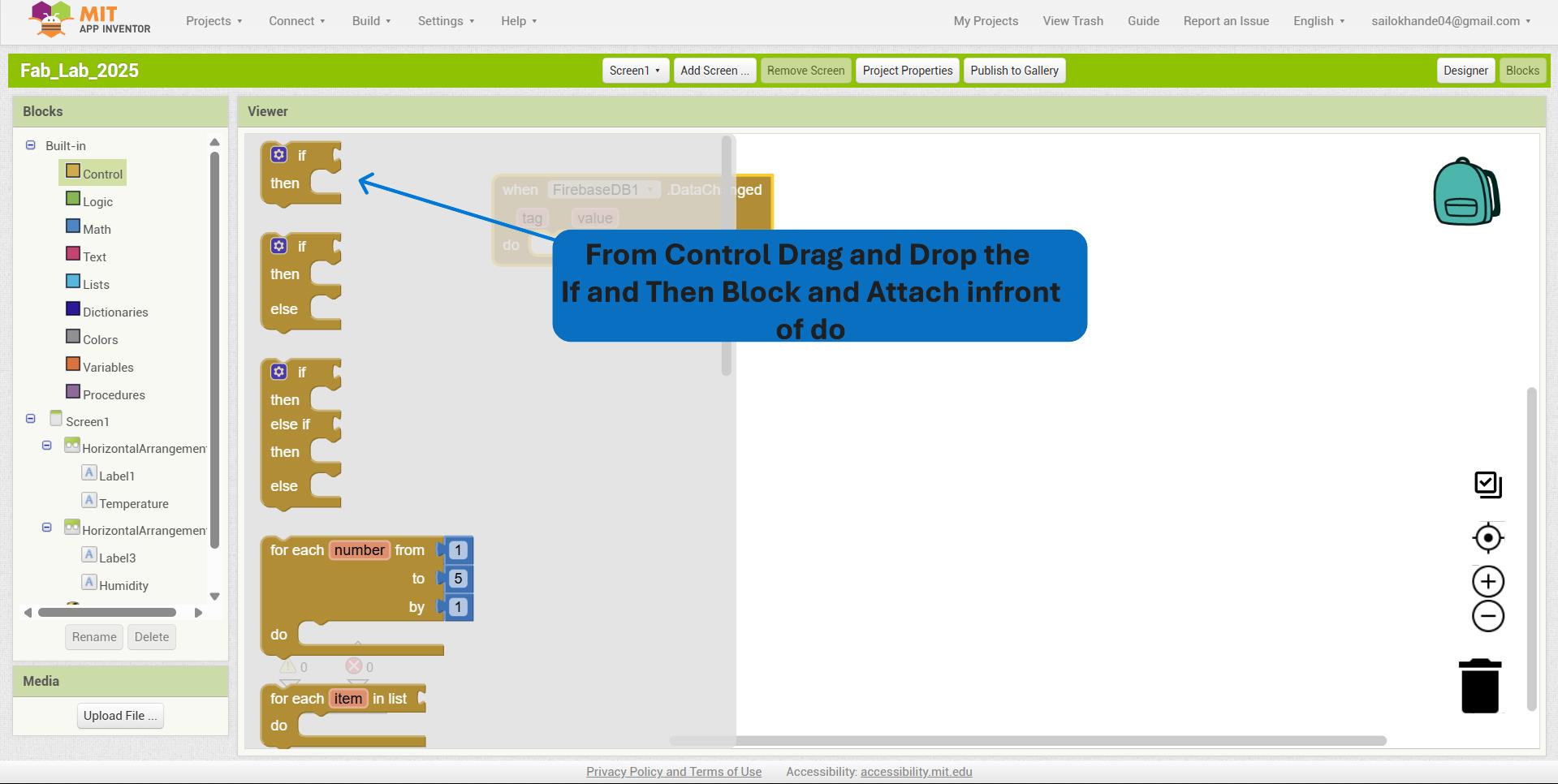
From the Control drawer, I dragged and dropped the if then block and attached it in front of the do section within the FirebaseDB1.DataChanged block to execute specific actions only when certain conditions are met.
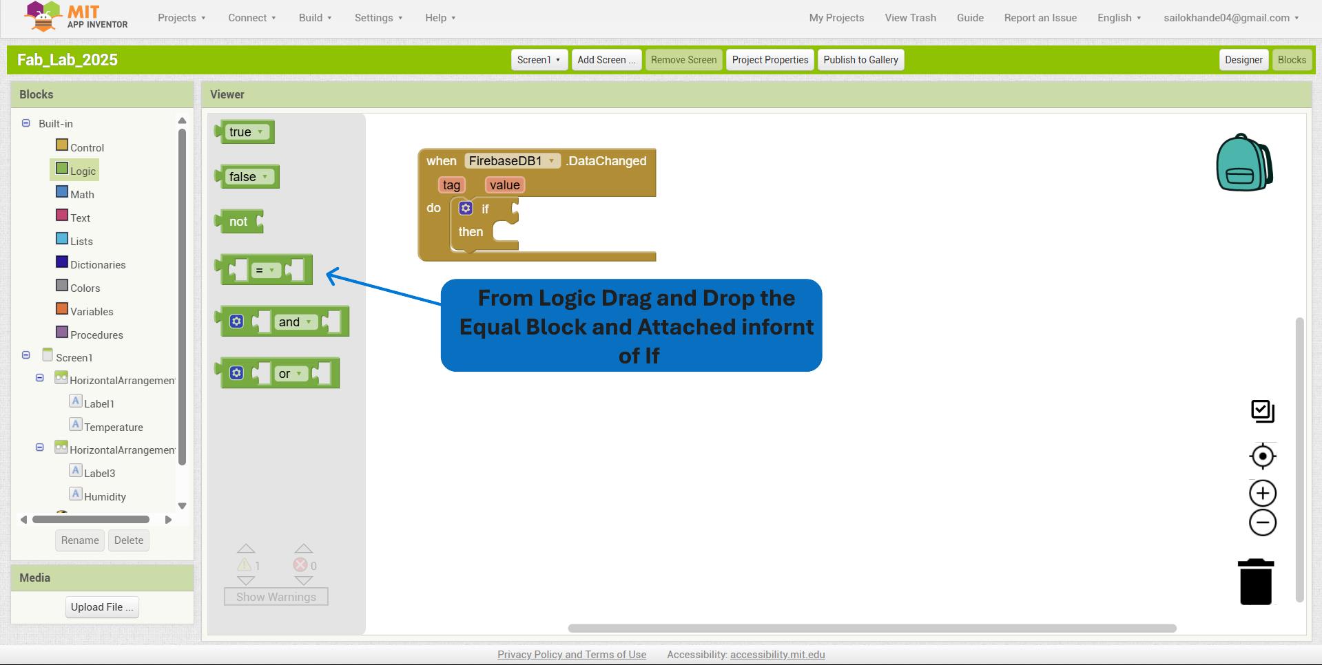
From the Logic drawer, I dragged and dropped the "equal to (=)" block and attached it in front of the if condition within the FirebaseDB1.DataChanged block to compare values and trigger actions based on specific criteria.
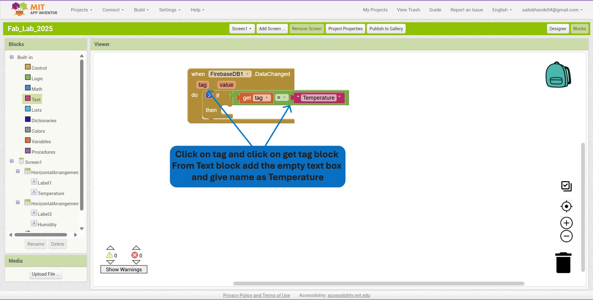
I clicked on the tag socket and inserted the get tag block from the FirebaseDB1.DataChanged section. Then, from the Text drawer, I added an empty text block and set its content to "Temperature" to compare the incoming data’s tag with the “Temperature” identifier.
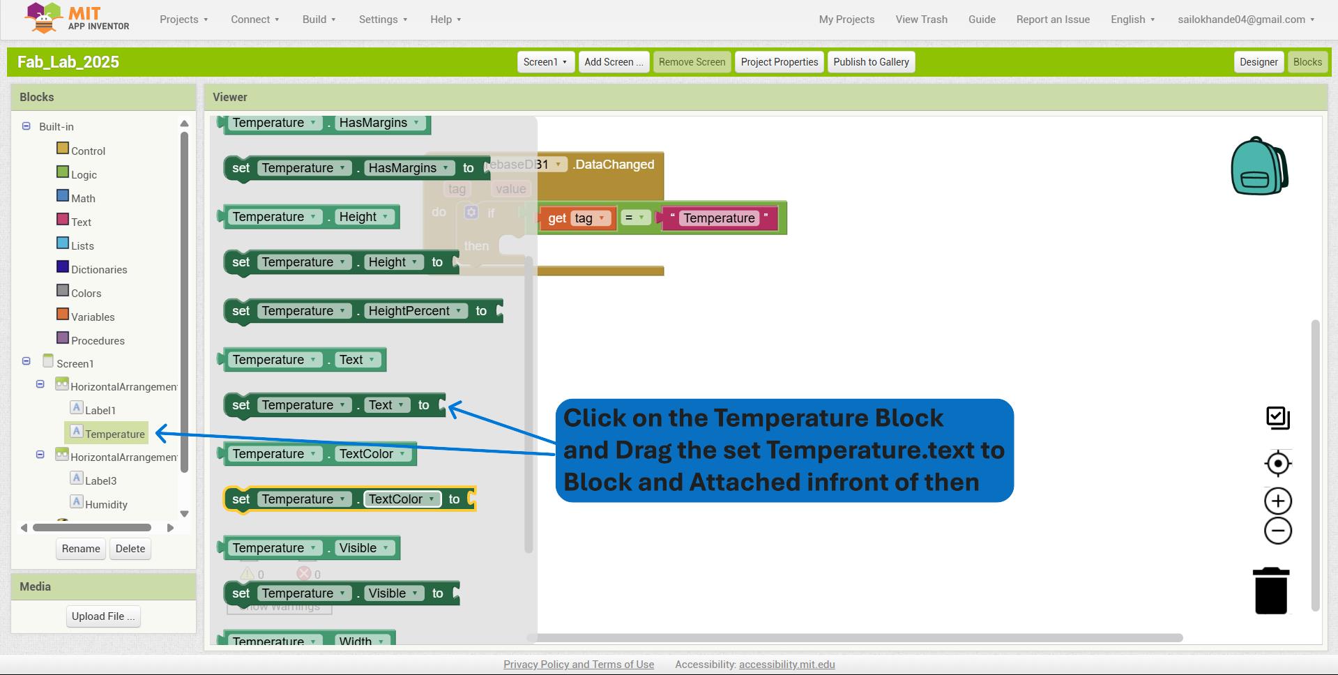
I clicked on the Temperature label block and dragged the set Temperature.Text to block into the workspace to update the label’s text dynamically based on data received.
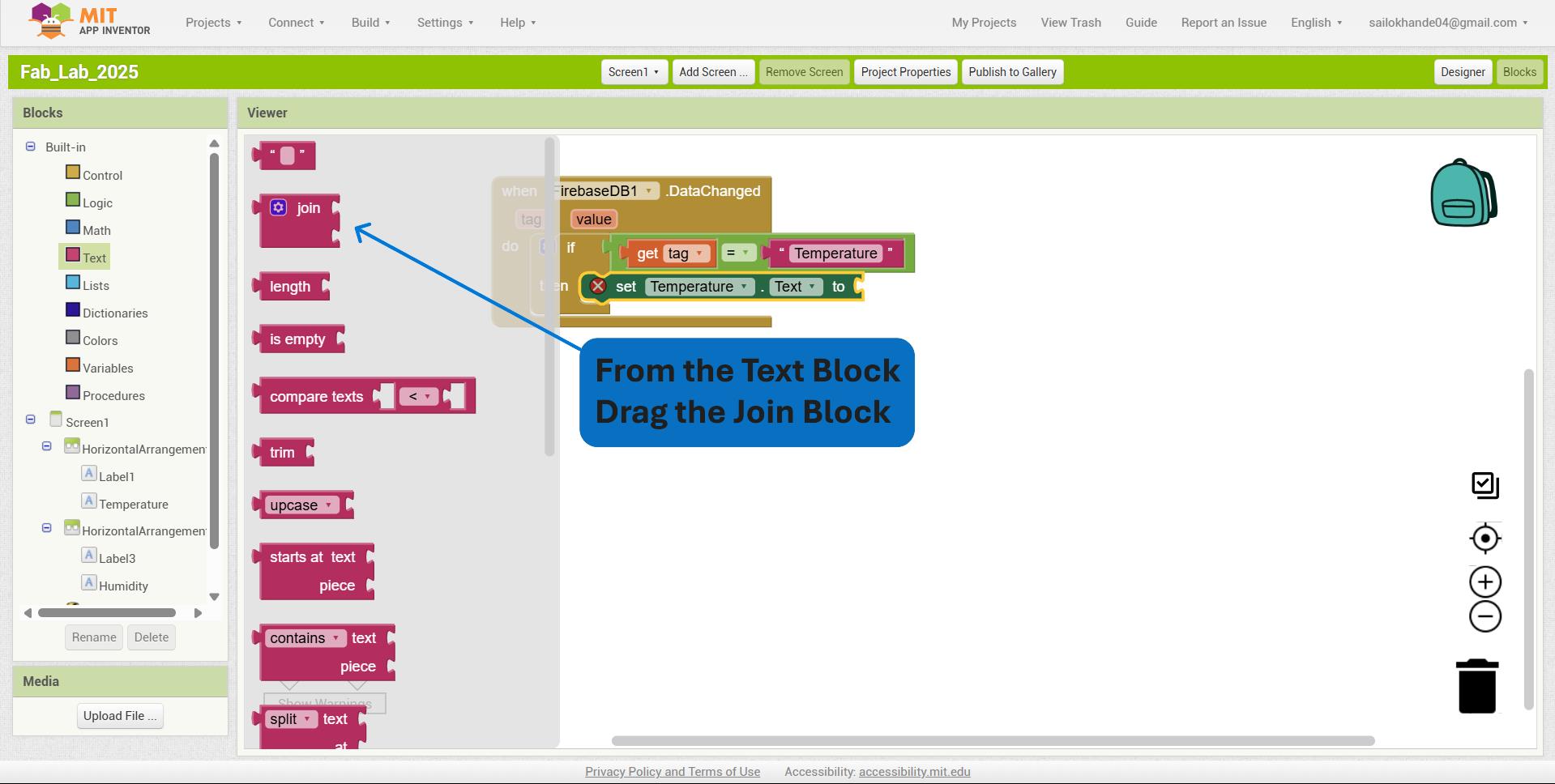
I added a join block from the Text drawer to concatenate multiple text elements, which allows me to combine a label (like "Temperature: ") with the dynamic data value for display.
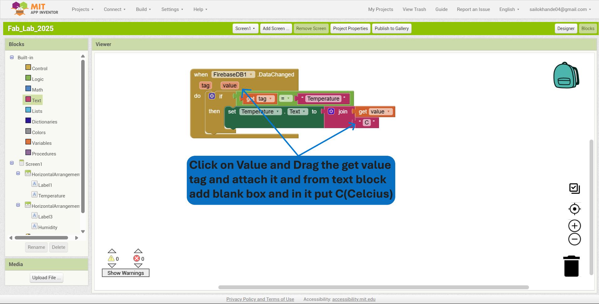
I added the get value block from the FirebaseDB1.DataChanged event and connected it to the join block, then appended the text " °C" to display the temperature value followed by the degree Celsius symbol.
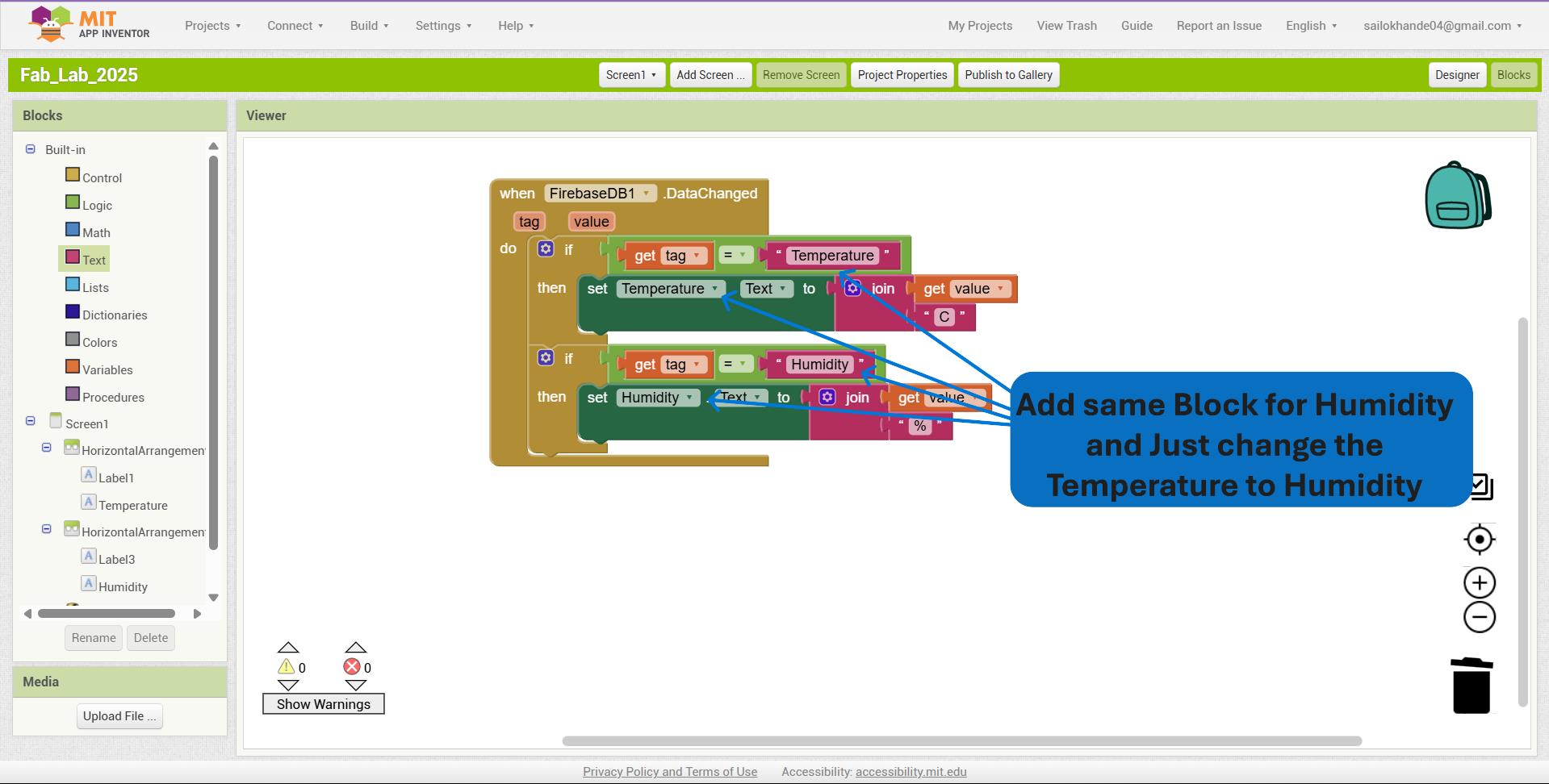
I repeated the same process for Humidity, replacing the tag from "Temperature" to "Humidity", and updated the label text to display the humidity value with the appropriate unit (e.g., %). This ensures the app dynamically shows both temperature and humidity data received from Firebase.
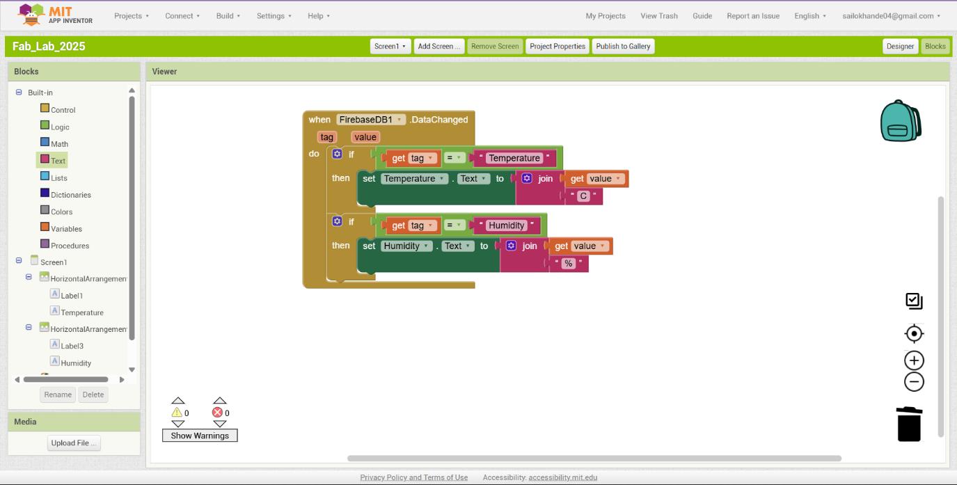
Full code
I entered the Firebase database URL into the FirebaseURL property box of the FirebaseDB1 component to establish the connection between the app and the Firebase Realtime Database.
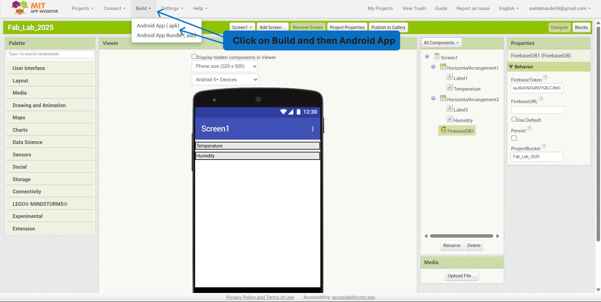
I navigated to the “Build” menu in MIT App Inventor, selected “App (provide QR code for .apk)” or “App (save .apk to my computer)”, then waited for the system to compile the application and downloaded the generated .apk file for installation on an Android device.
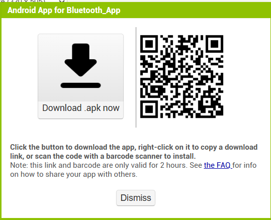
This is the QR code using this the app can be downloaded.
I developed a program to read real-time temperature and humidity data using a DHT sensor and an ESP32-C3.
#include < Wire.h >
#include < Firebase_ESP_Client.h >
#include "DHT.h"
// Wi-Fi credentials
#define WIFI_SSID "SMK"
#define WIFI_PASSWORD "12345678"
// Firebase project credentials
#define API_KEY "AIzaSyC9ajXRHNJwZffxFwZakIFiZ6nHlhoTM0I"
#define DATABASE_URL "https://fab-academy-f2a47-default-rtdb.firebaseio.com/" // Do NOT add "https://"
// DHT Sensor
#define DHTPIN 3 // GPIO3
#define DHTTYPE DHT11
DHT dht(DHTPIN, DHTTYPE);
// Firebase objects
FirebaseData fbdo;
FirebaseAuth auth;
FirebaseConfig config;
void setup() {
Serial.begin(115200);
dht.begin();
WiFi.begin(WIFI_SSID, WIFI_PASSWORD);
Serial.print("Connecting to Wi-Fi");
while (WiFi.status() != WL_CONNECTED) {
Serial.print(".");
delay(300);
}
Serial.println("\n✅ Connected to Wi-Fi");
// Firebase setup
config.api_key = API_KEY;
config.database_url = DATABASE_URL;
// Anonymous authentication
auth.user.email = "";
auth.user.password = "";
Firebase.begin(&config, &auth);
Firebase.reconnectWiFi(true);
}
void loop() {
float temp = dht.readTemperature();
float hum = dht.readHumidity();
if (isnan(temp) || isnan(hum)) {
Serial.println("❌ Failed to read from DHT sensor!");
return;
}Serial.print("🌡 Temp: ");
Serial.print(temp);
Serial.print("°C | 💧 Humidity: ");
Serial.print(hum);
Serial.println("%");
if (Firebase.ready()) {
if (Firebase.RTDB.setFloat(&fbdo, "/sensor/Temp", temp)) {
Serial.println("✔ Temp uploaded");
} else {
Serial.print("❌ Temp upload error: ");
Serial.println(fbdo.errorReason());
}
if (Firebase.RTDB.setFloat(&fbdo, "/sensor/Humi", hum)) {
Serial.println("✔ Humidity uploaded");
} else {
Serial.print("❌ Humidity upload error: ");
Serial.println(fbdo.errorReason());
}
}
delay(5000); // 5-second interval
}
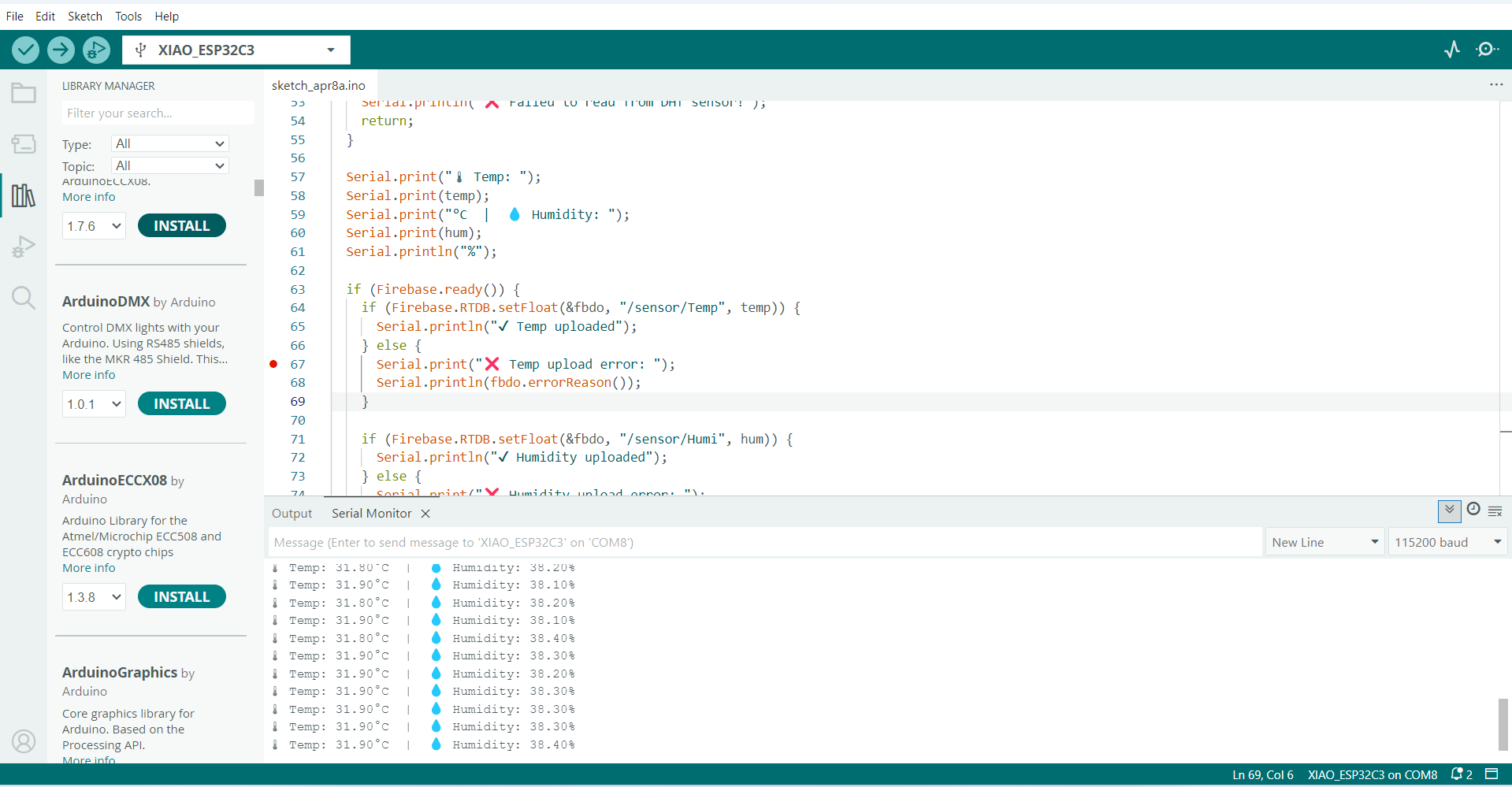
Then uploading it to the XIAO ESP32-C3.
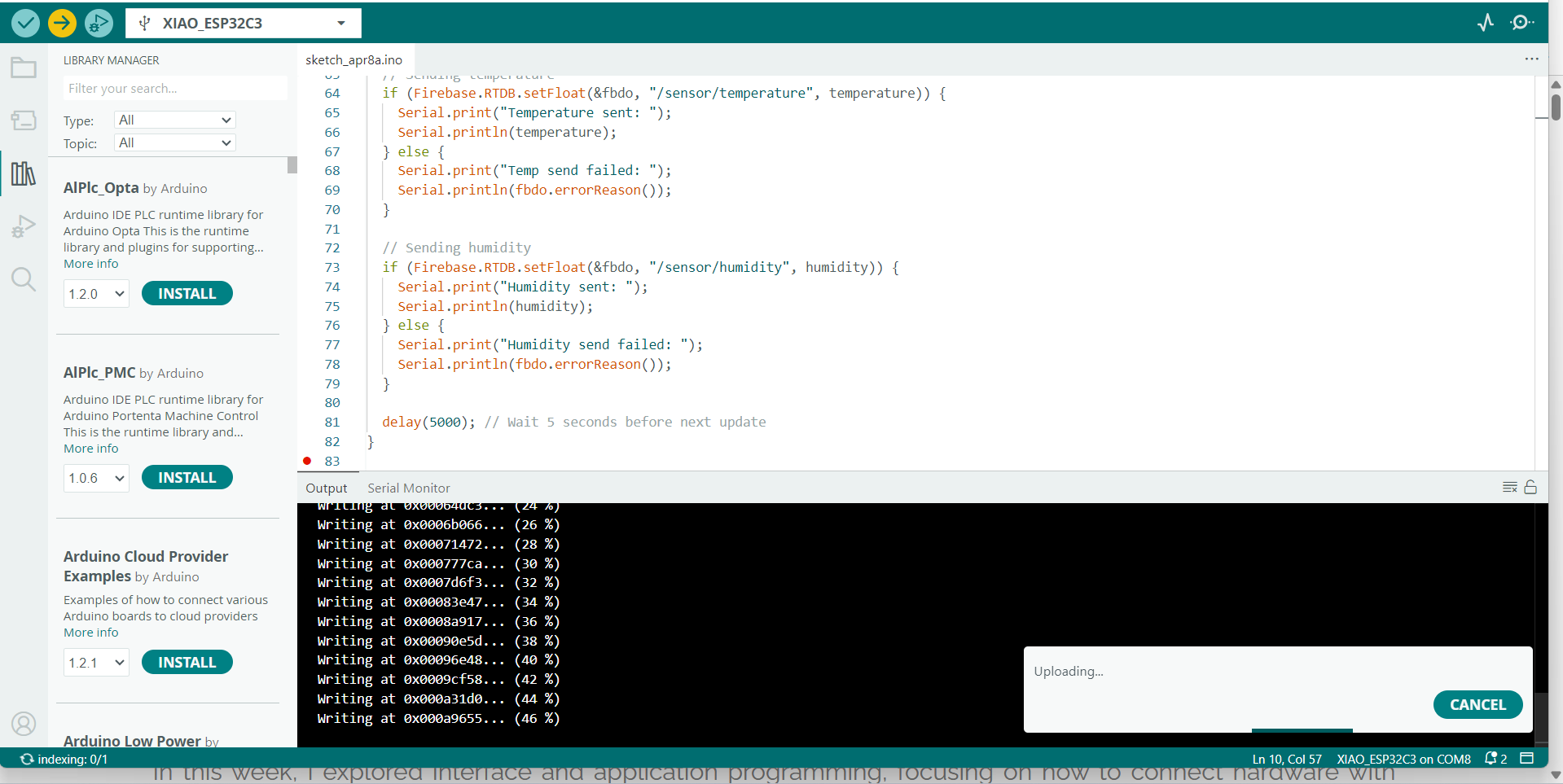
The figure displays the Arduino IDE environment used to program the XIAO ESP32-C3 microcontroller for real-time temperature and humidity monitoring. The Serial Monitor output at the bottom confirms that the ESP32-C3 is successfully reading temperature and humidity data from the DHT11 sensor, displaying values such as Temp: 31.90°C and Humidity: 38.60%.
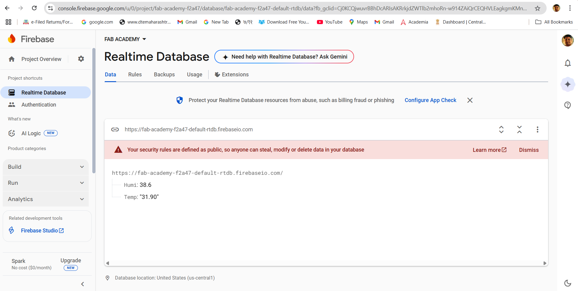
The figure displays the Firebase Realtime Database dashboard for the project titled "FAB ACADEMY". It shows that the ESP32-C3 has successfully uploaded real-time sensor data, specifically:
Temp: 31.90°C
Humi: 38.6%
These values confirm that the data transmission from the microcontroller to the Firebase database is functioning correctly.
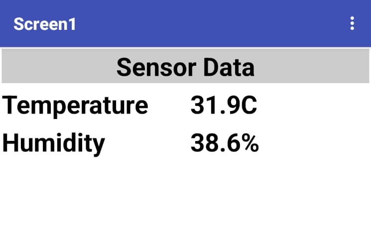
The mobile application interface used to visualize real-time sensor data retrieved from Firebase. The app shows the current readings from the temperature and humidity sensor connected to the ESP32-C3 microcontroller:
Temp: 31.90°C
Humi: 38.6%
The layout is simple and user-friendly, with clear formatting under the header "Sensor Data". This mobile display confirms successful integration between the ESP32-C3, Firebase Realtime Database, and the Android app—enabling real-time environmental monitoring on a mobile device.