Week 2
Computer-Aided Design
In this assignment, the goal is to explore various modeling techniques, including raster and vector graphics, 2D and 3D modeling, rendering, animation, and simulation.I will likely use a combination of software tools for different modeling techniques.
1. Raster Image
In computer graphics and photography, raster images are commonly used. These images are typically two-dimensional and composed of tiny squares called pixels. Each pixel has a specific color and position, and when combined, they form a complete image.
A raster image also known as a bitmap image is a type of digital image in which the resolution is determined by the number of pixels per inch (PPI). Higher PPI results in better image quality, while lower PPI can make the image appear pixelated when enlarged.
GIMP (GNU Image Manipulation Program)
GIMP is a free, open-source, cross-platform image editing tool available for GNU/Linux, macOS, Windows, and other operating systems. It is a powerful, easy-to-use, and highly efficient image editing software that supports various tasks, including image retouching, freehand drawing, and format conversion. Additionally, GIMP offers numerous advanced features, making it a top choice among photo editing software.The default file extension for images created or modified in GIMP is .xcf (Experimental Computing Facility).
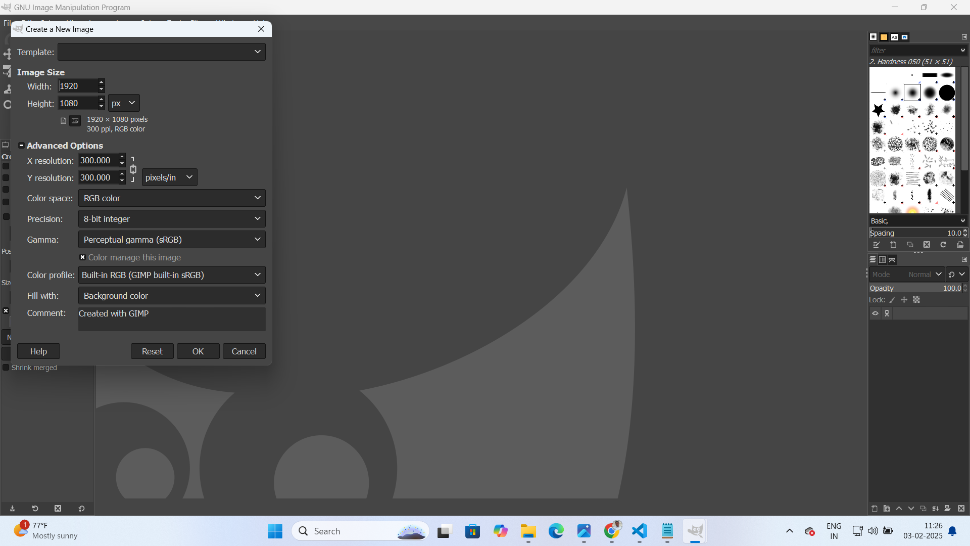
Firstly, I opened the GIMP and click on "New" from "File" tab to insert fresh blank document so that I can start to design my drawings. After clicking on "New" option they are asking to enter page layout including height and width. So, enter required dimensions as per your need.
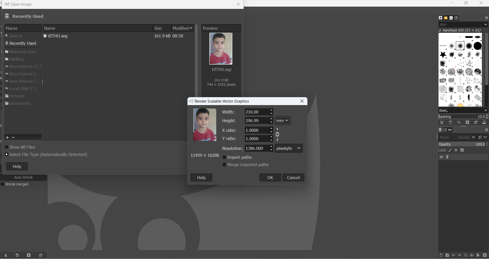
Using the GIMP image editing software, users can modify various attributes of an image, such as width, height, X-ratio, Y-ratio, and resolution. To change the background of an image, follow these steps:
First, select the desired image from my computer. Once the image is loaded into GIMP, adjust its properties, including width, height, X-ratio, Y-ratio, and resolution, as needed. These modifications ensure that the image is properly scaled and optimized for further editing.
Select the Free Select Tool: Click on the "Free Select Tool" and carefully trace the boundary of the subject in the image to create a selection.
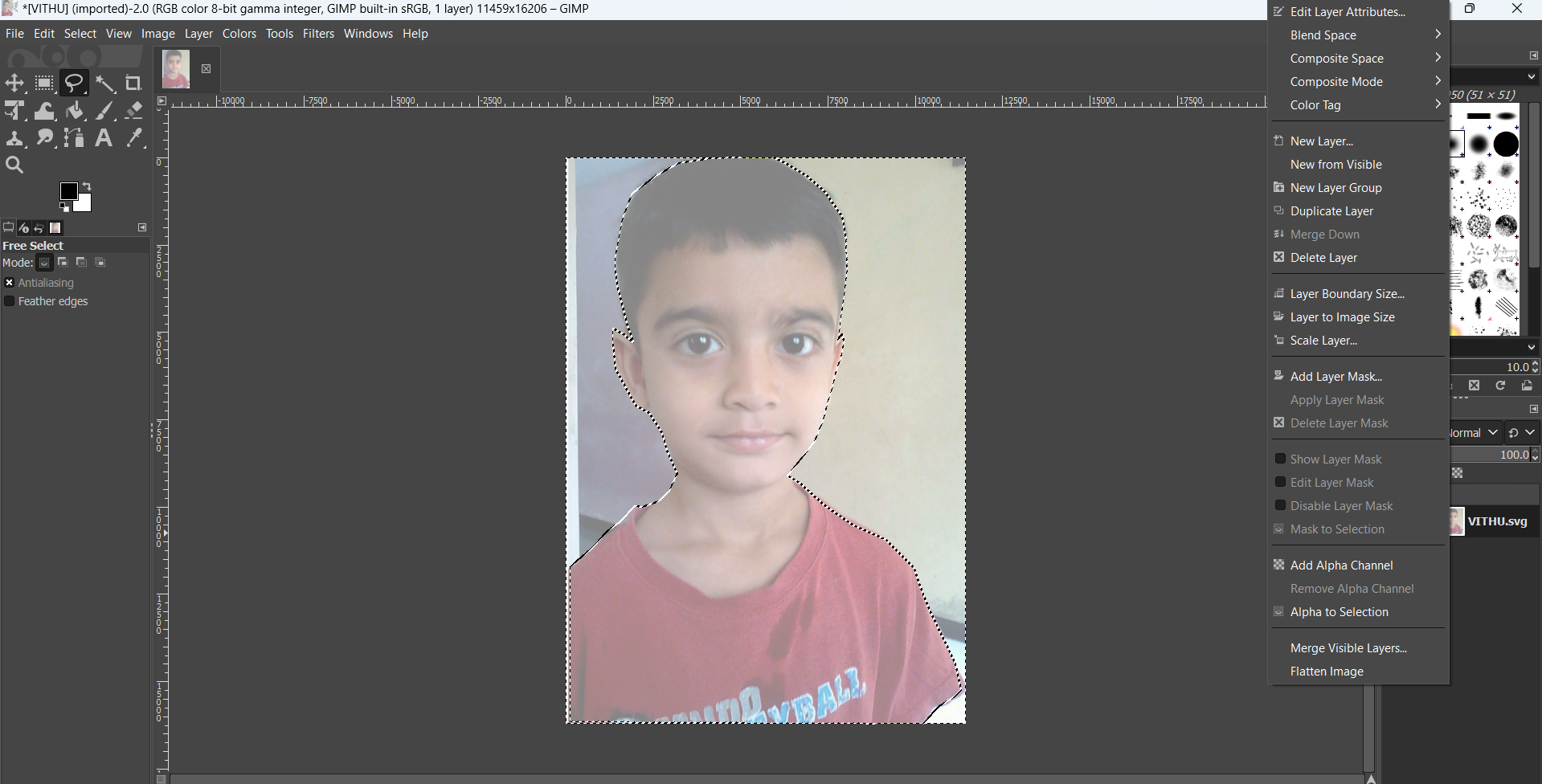
Invert the Selection: Once the subject is selected, navigate to the Select menu and choose Invert to select the background instead of the subject.
Add an Alpha Channel: Right-click on the image layer and select Add Alpha Channel to enable transparency.
Erase the Background: Choose the Eraser Tool and carefully erase the selected background. Only the unselected part (the background) will be removed, leaving the subject intact.
Export the Image as PNG: Go to the File menu, select Export As, change the file extension to .png, and export the image to a desired folder.

2. Vector Image:
A vector image is a type of digital graphic that uses mathematical equations to represent images. Unlike raster images (which are made up of pixels), vector images are composed of paths, defined by points, lines, curves, and shapes. These paths are based on mathematical formulas, allowing vector images to be scaled infinitely without losing quality.
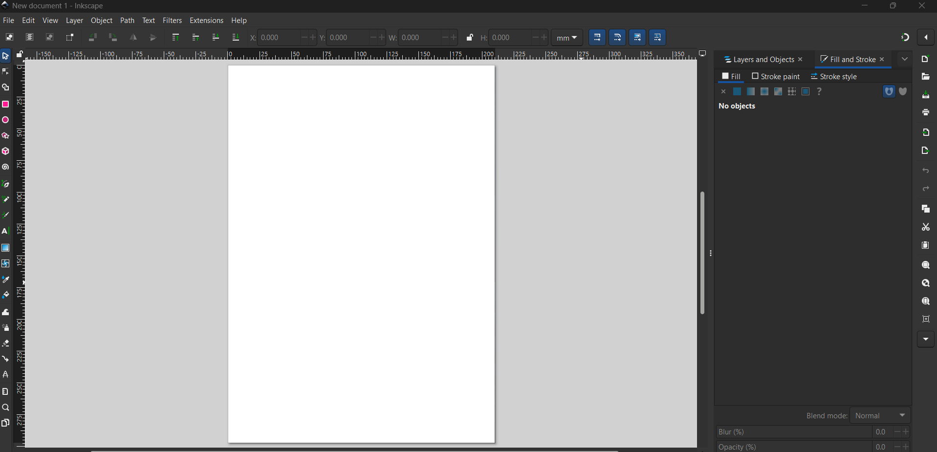
Inkscape Software
Inkscape is a free and open-source vector graphics editor that provides a powerful and versatile platform for creating and editing scalable vector graphics (SVG).Inkscape is widely used by designers, illustrators, and hobbyists for various tasks, including logo design, illustration creation, and web graphics production.
Inkscape supports multiple file formats, including SVG, PDF, and EPS, and is compatible with Windows, macOS, and Linux. Whether working on branding, digital art, or print media, Inkscape’s flexibility and scalability make it an invaluable tool for producing high-quality vector graphics.
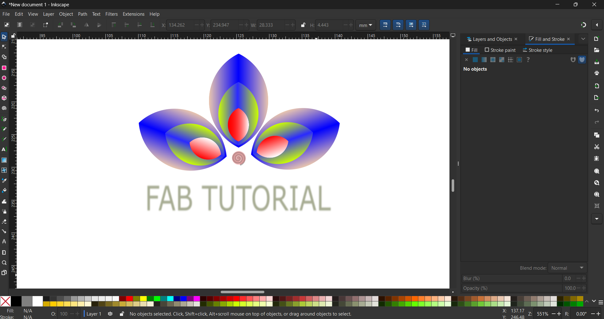
Below the screen of the Inkscape software, users can find various tools and options that enhance the design process. This includes the status bar, which provides essential information about the selected objects, layer details, and zoom controls. Additionally, alignment and snapping options are available to ensure precision in vector design. These features contribute to a seamless and efficient workflow for both beginners and experienced users.
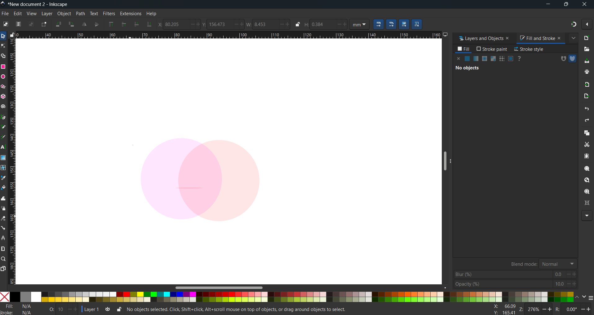
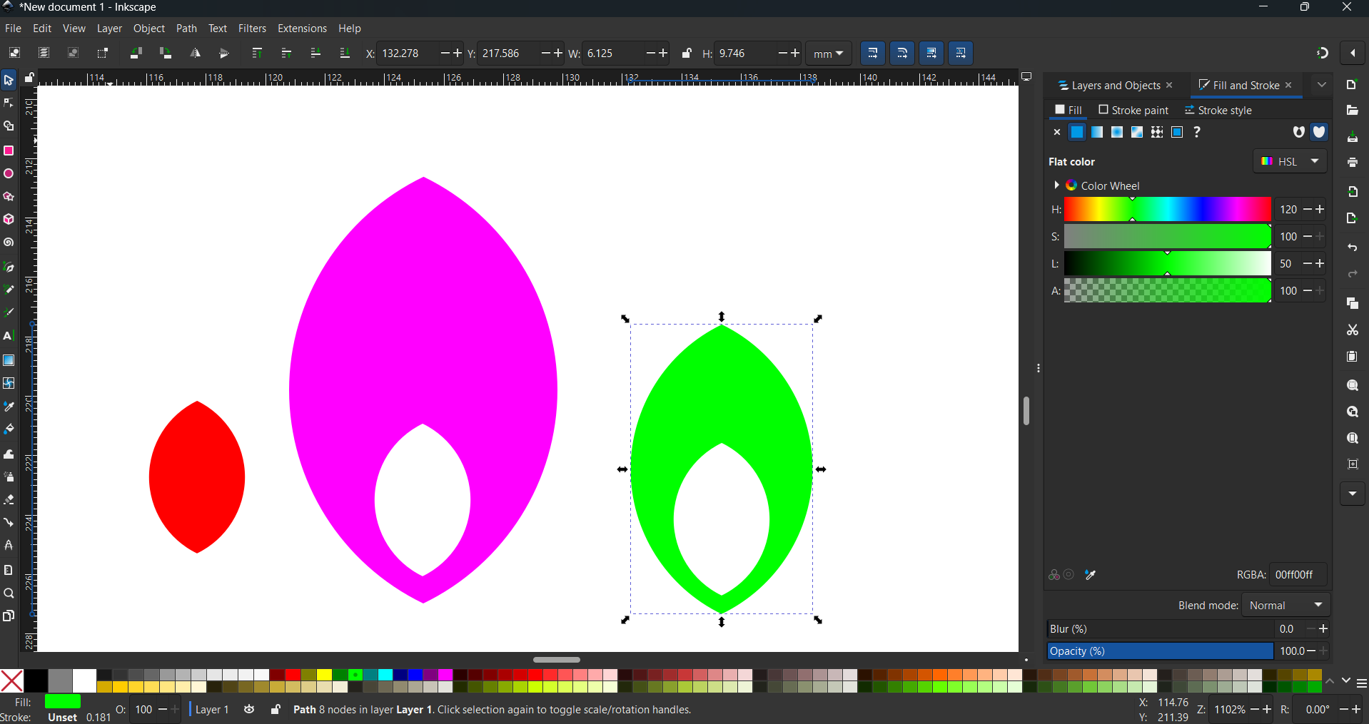
Select the Ellipse Tool from the toolbar, then hold the Control key while dragging to create a perfect circle. Right-click on the circle and select Duplicate to create a copy. Apply a red color to the duplicated shape. Next, drag the duplicate to the right side and adjust its opacity to 50% for a transparent effect.
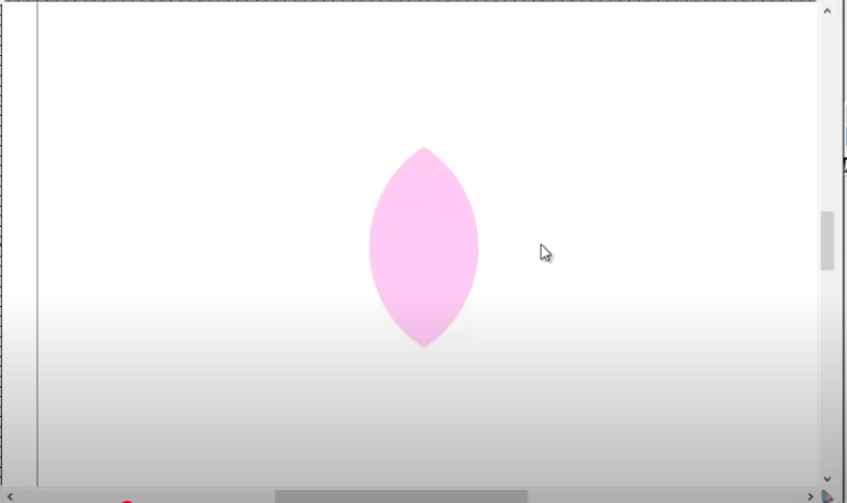
To obtain only the intersecting surface of the two circles, first, select both circles. Then, navigate to the Path menu and choose the Intersection command. This will retain only the overlapping area of the two shapes while removing the rest.
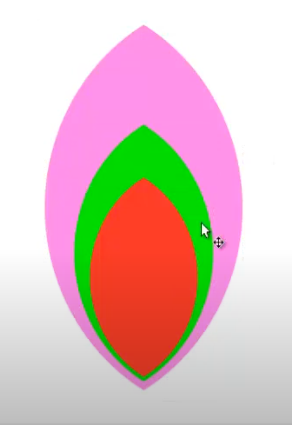
Create two duplicates of the intersecting shape, applying a different color to each duplicate. Using the mouse, drag and resize them precisely to achieve the desired shape.
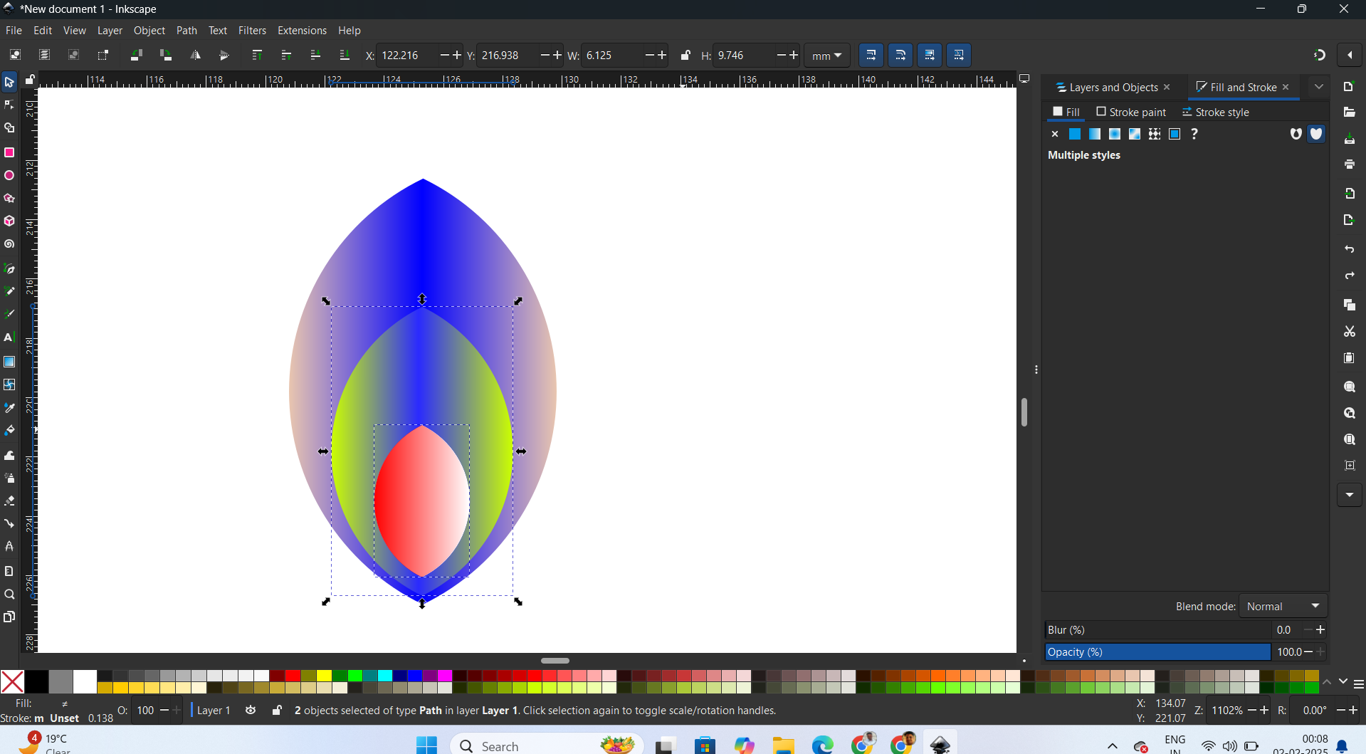
Select the entire shape and create a duplicate. Then, select one shape, navigate to the Path menu, and choose the Difference command. Repeat this process for the remaining two shapes. Finally, use the mouse to drag each shape one by one to the left and right sides to achieve the desired design.
Select the outer shape and navigate to the Fill panel. Choose Linear Gradient and set the opacity to 100%. Apply a blue color to the gradient, then select the gradient and press Ctrl + G to group it. Next, choose the desired color for the gradient.
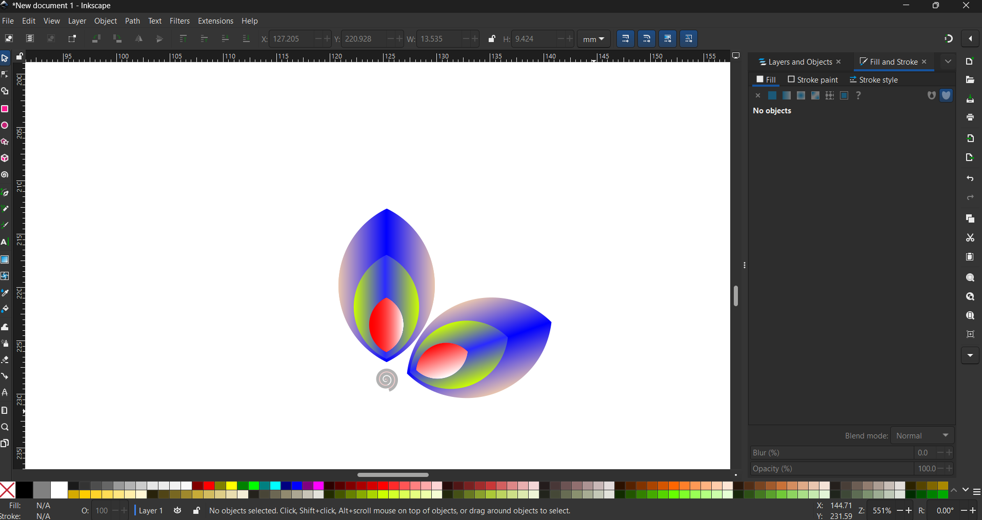
Select the Spiral Tool and create the desired shape by holding Ctrl while dragging to adjust its size. Position the spiral shape at the center below the existing design. Apply color using the Fill panel and choose Linear Gradient for a smooth effect.
Next, select the entire shape, right-click, and choose Duplicate. Click on the duplicated shape and rotate it to the desired position for proper alignment in right side.
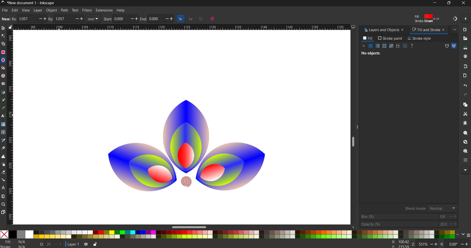
Repeat the same procedure for the duplicated shape, and then rotate it to the left side to achieve the desired position and proper alignment.
Select the Text Tool and create the text "FAB TUTORIAL." Adjust the text to the desired shape. Then, select the text, navigate to the Fill panel, and choose Linear Gradient, setting the opacity to 100%. Apply the desired color to the gradient. Afterward, select the gradient and press Ctrl + G to group it. Finally, choose the appropriate color for the gradient.
3. Compression of Image and Video
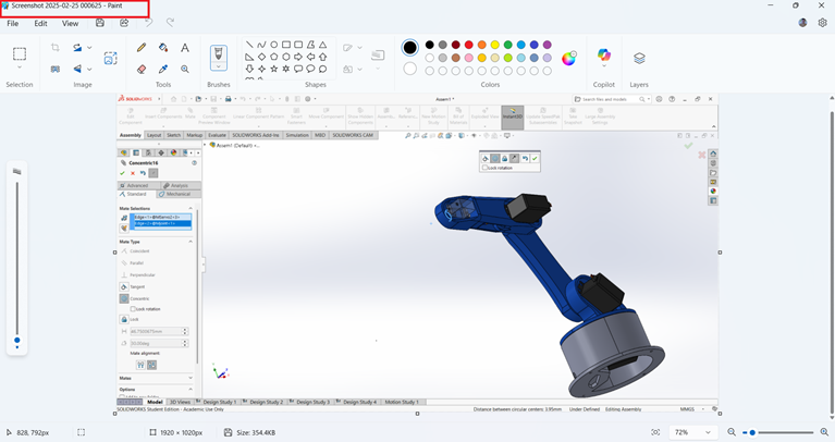
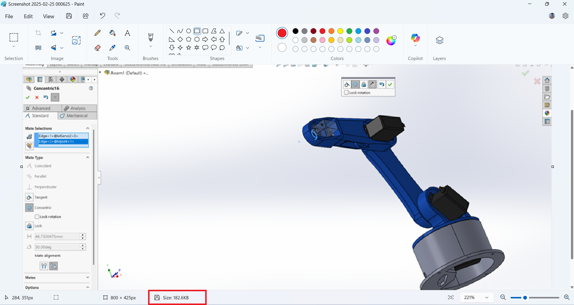
I have been using Microsoft Paint for a long time to compress images efficiently.
To resize an image, open it in Microsoft Paint.
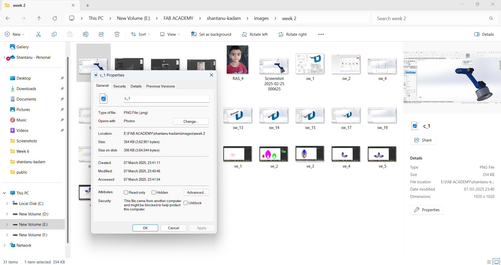
If your selected image has a size of 354 KB, you can reduce its size using Microsoft Paint. Right-click on the image, select "Open with," and then choose "Paint."
Click on "Resize" in the toolbar, select "Pixels," and reduce the width and height while maintaining the aspect ratio.
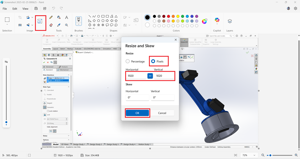
Click OK and save the image.Size reduce to 182 kb. This procedure to compression the image.
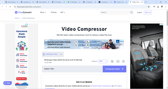
For video compression, I can use an online method by selecting the FreeConvert website
Then, click on "Choose File," and select the file from the desired location on your system.
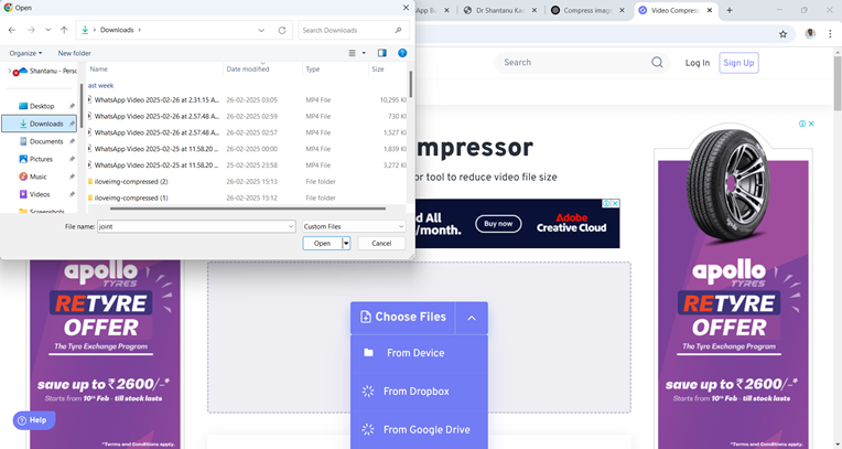
Select "Open" and then click "Compress Now" to start the compression process.
As soon as the compression is complete, click on "Download" to save the compressed file.
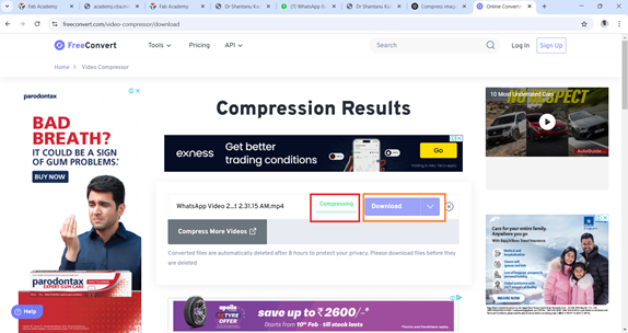
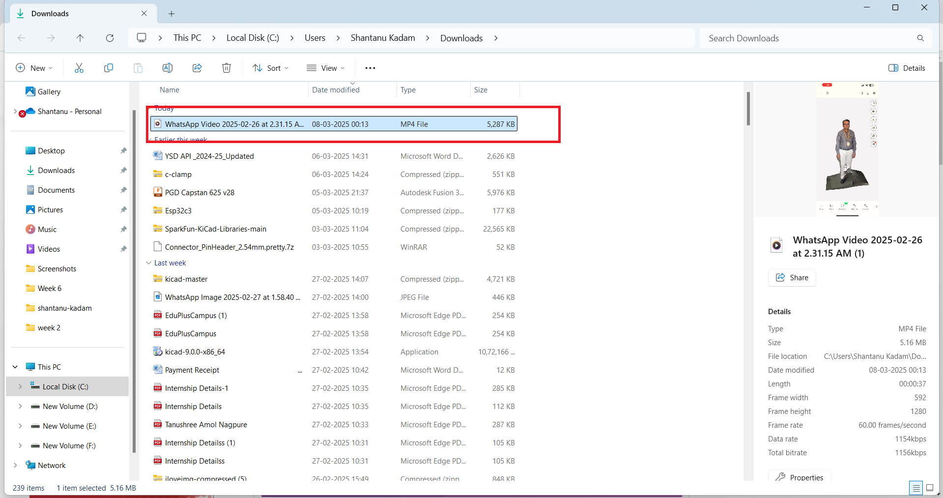
The compressed file is then saved to the Downloads folder.
4. Solid Work
SolidWorks is a powerful computer-aided design (CAD) software. It is widely used in engineering, product design, and manufacturing for creating 3D models, simulations, and detailed technical drawings. SolidWorks offers parametric and direct modeling capabilities, allowing users to design complex mechanical parts and assemblies efficiently. It also provides simulation, motion analysis, and rendering tools to evaluate designs before production. Due to its user-friendly interface and integration with CAM (Computer-Aided Manufacturing) and CAE (Computer-Aided Engineering) tools, SolidWorks is a preferred choice for engineers and designers in various industries.
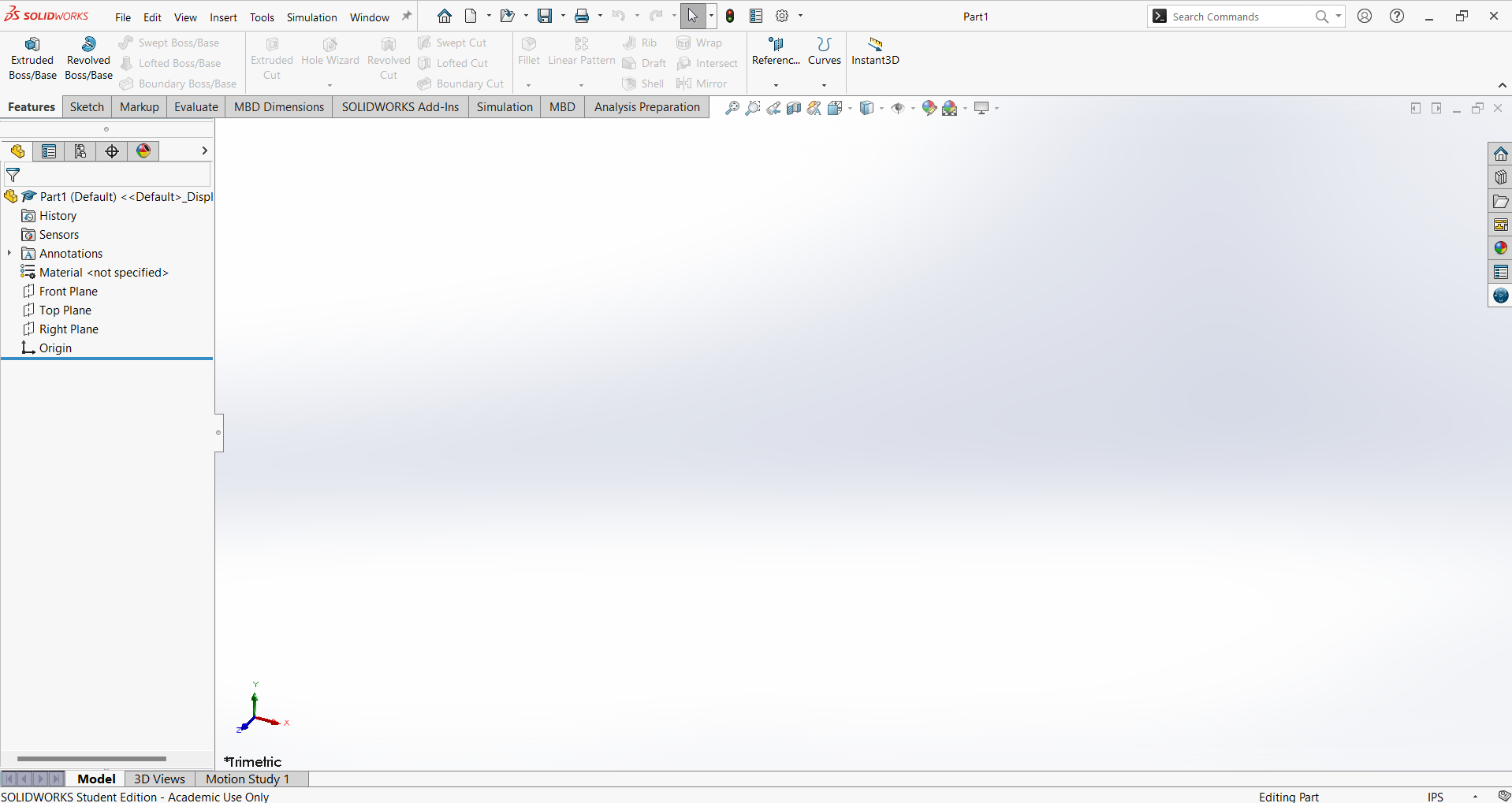
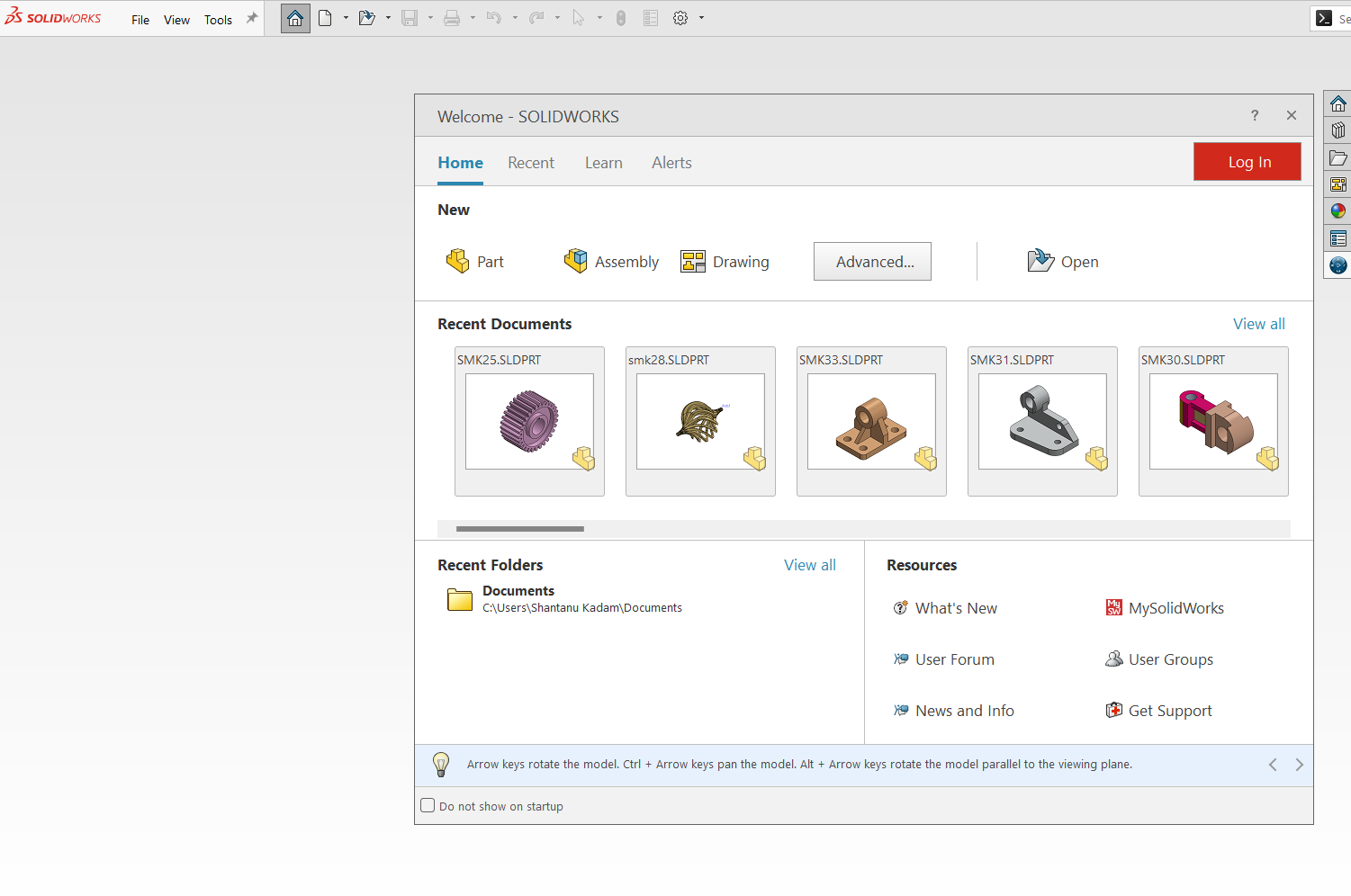
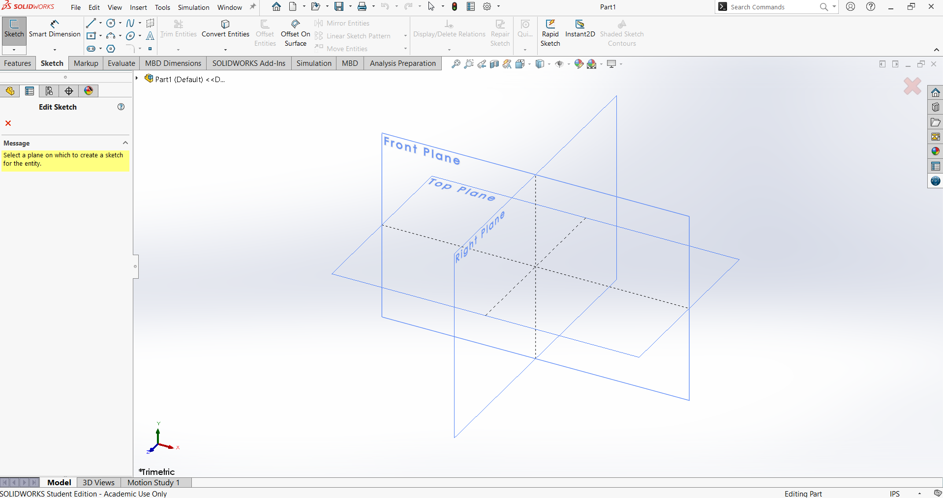
This is the SOLIDWORKS window displayed after launching the software.
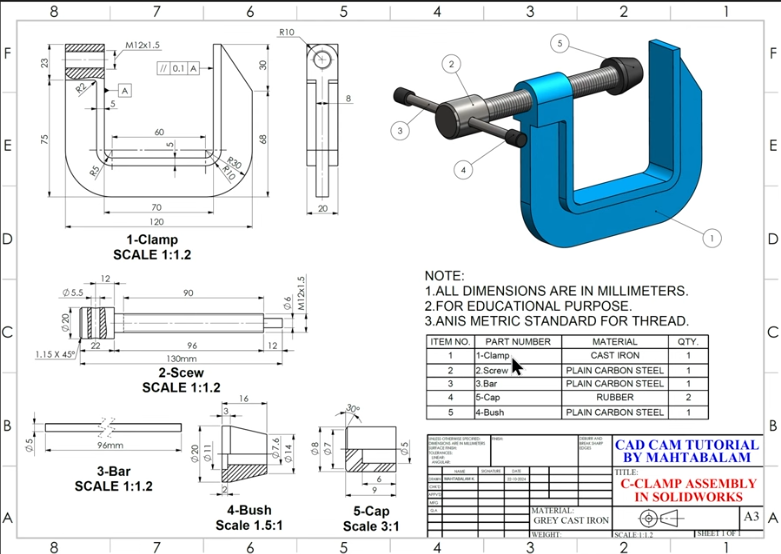
Let's create a C-Clamp in SOLIDWORKS. We will develop five parts: clamp, screw, bar, cap, and bush
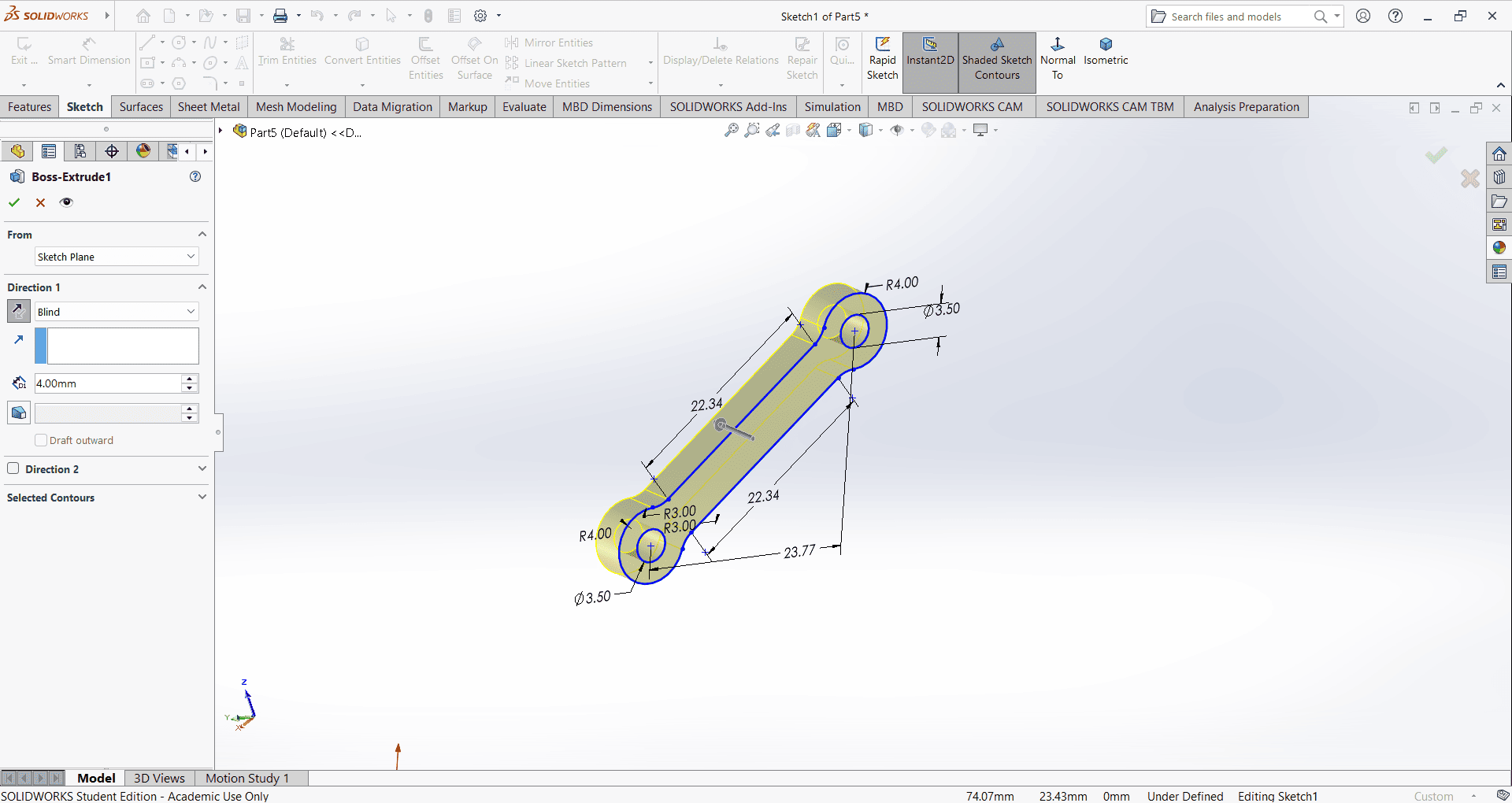
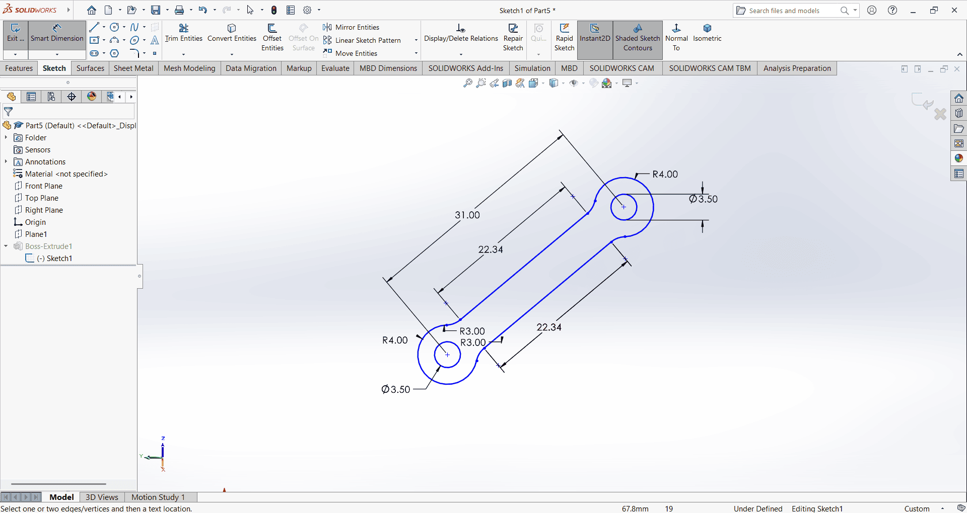
Start the SOLIDWORKS tutorial by selecting the Part option. Then, choose Sketch and select the Right Plane
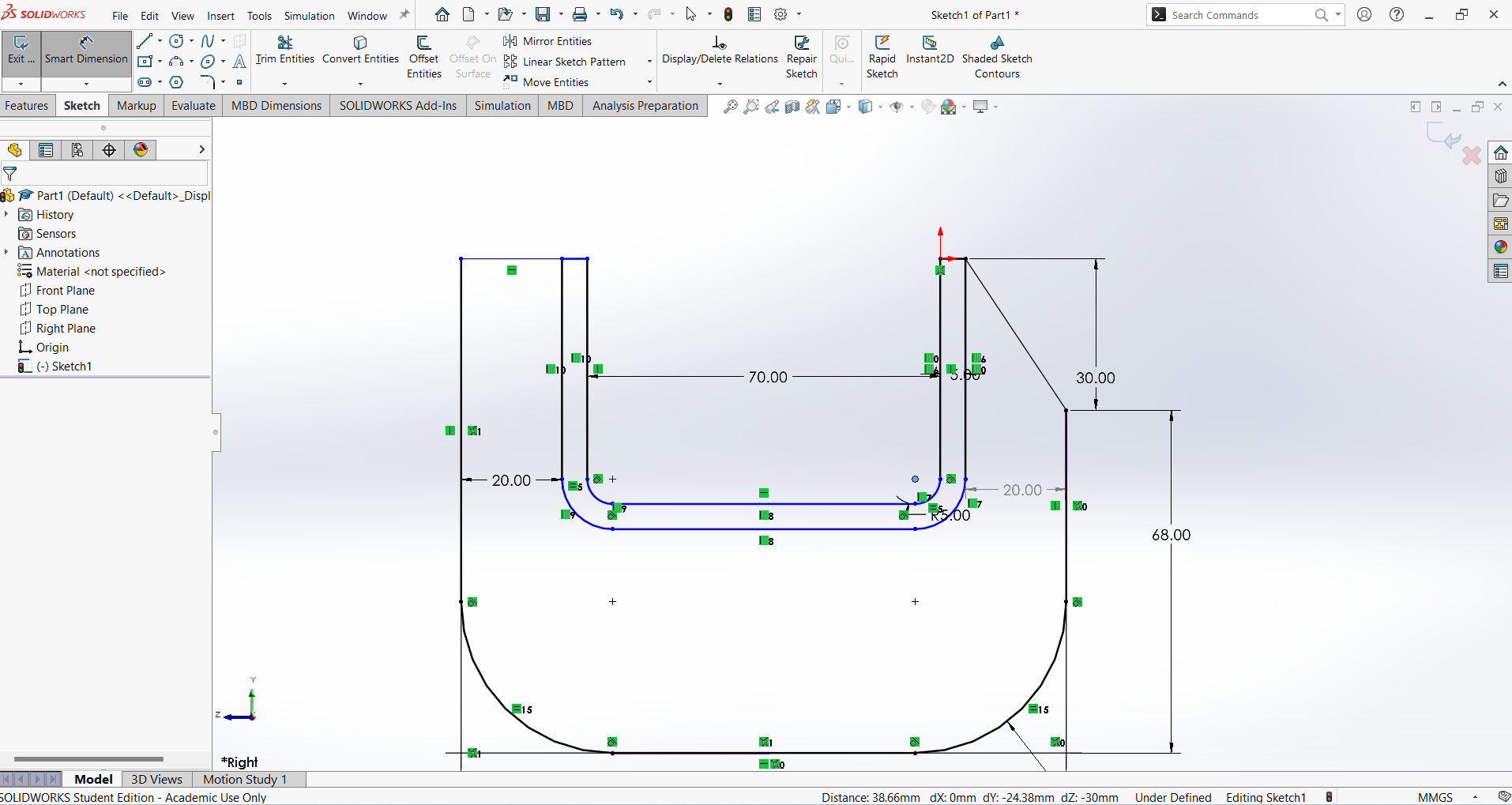
First, select the Line command, followed by Fillet and Offset. Then, apply the Smart Dimension command. These commands, along with their subcommands, are used to create a 2D sketch.
Select the Extrude Boss/Base command and use the Mid Plane option for the outer surface. Then, select the inner surface and apply the Extrude Boss/Base command again, using the Mid Plane option. The outer surface should be extruded by 20 mm, while the inner surface should be extruded by 8 mm."
Select the required side view of the object to create the circular part. Use the Circle Tool to draw a circle. Next, select a vertical line and the circle, then apply the Tangent relation. Repeat this process for the remaining two lines and the circle to ensure tangency.
Then, use the Line Tool to create a rectangle below the semicircle. Select the Trim Tool and use the Power Trim option to remove any unwanted lines. Apply Smart Dimension to adjust the shape according to the drawing specifications.
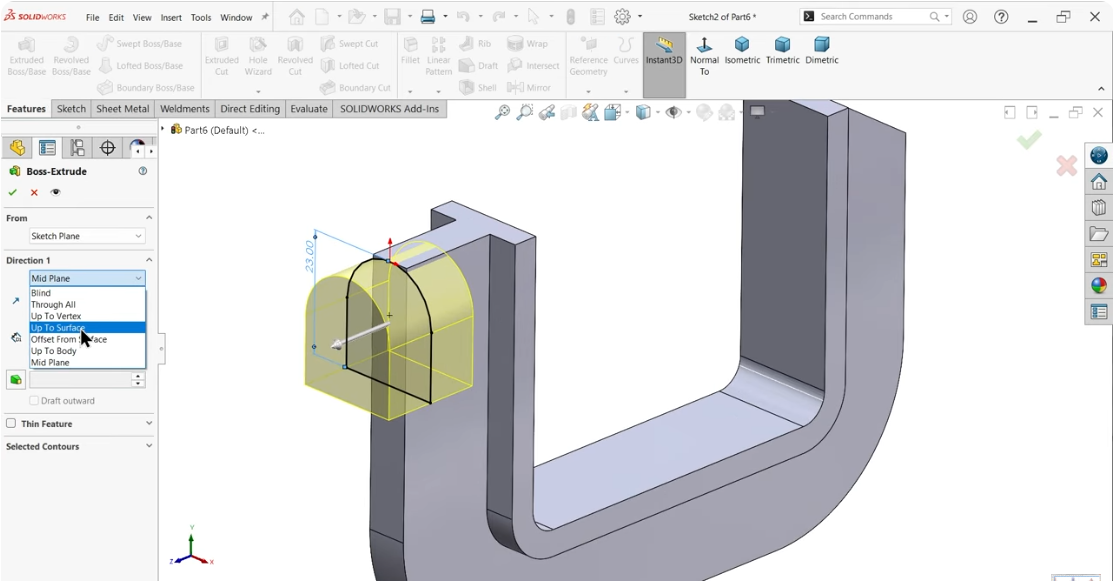
Once the sketch is complete, exit the sketch mode and select Extrude Boss/Base. In the Extrude Boss/Base settings, choose Up to Surface as the Direction 1 option to finalize the extrusion.
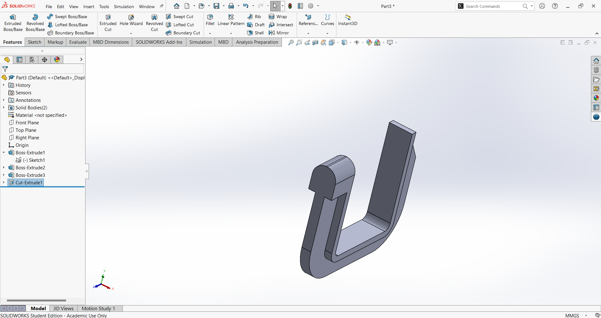
Select the same side view to create a hole with an internal thread. Open the Hole Wizard tool and configure the following specifications:
Hole Type: Straight Tap
Standard: ANSI Metric
Size: M12 × 1.5
End Condition: Up to Next
Apply the settings to generate the threaded hole as per the required specifications.
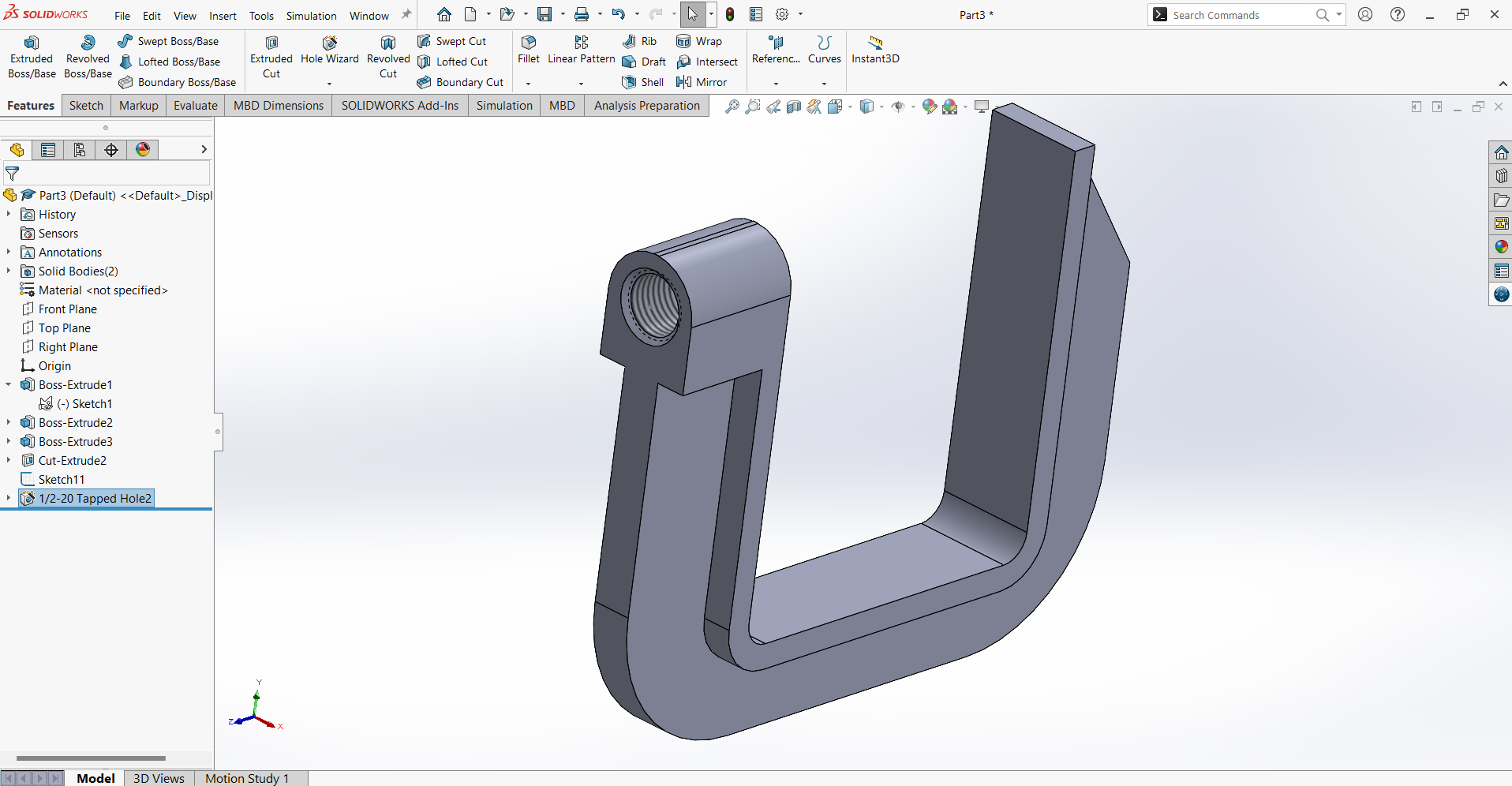
Once the clamp is completed, save the file.
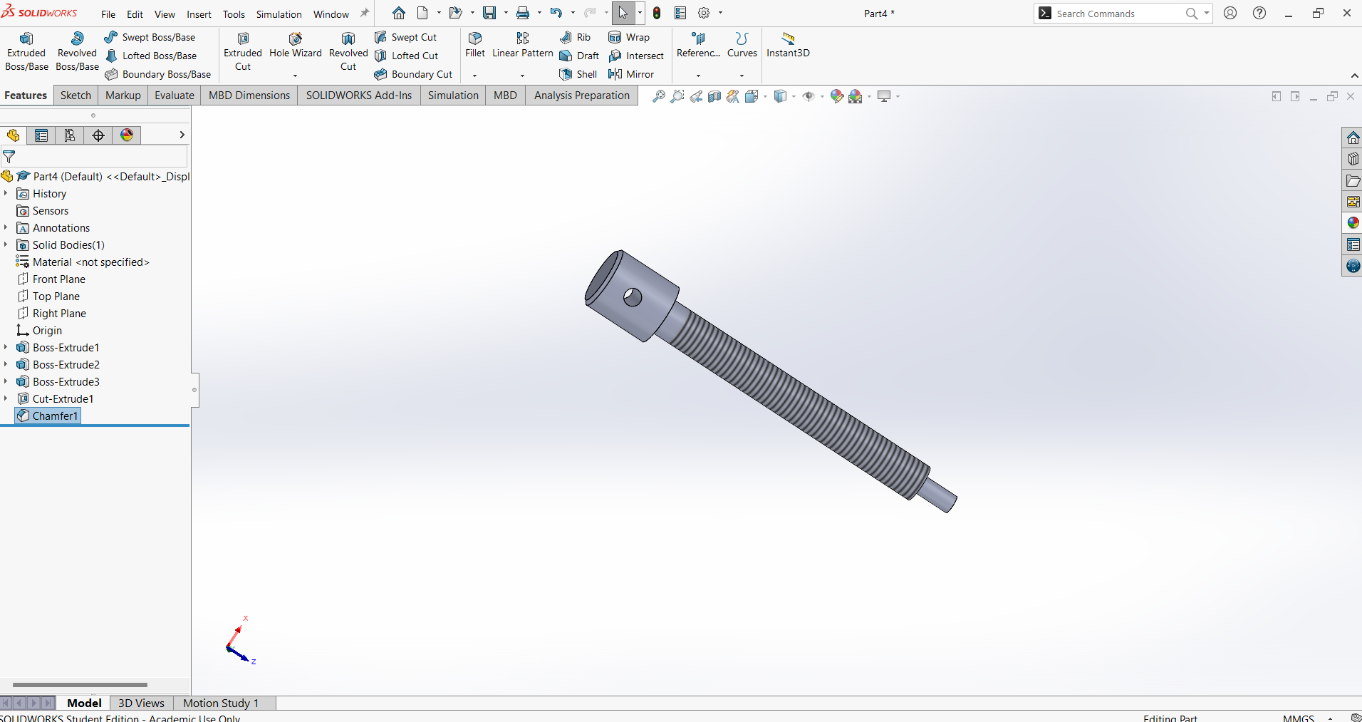
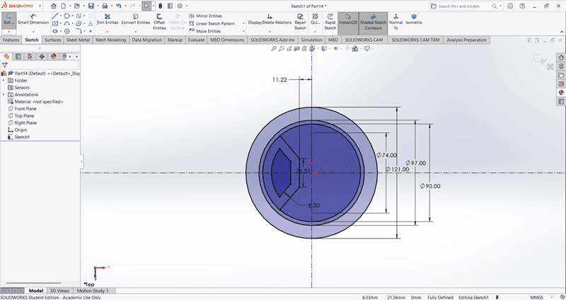
Next, create a new part by selecting New from the File menu and begin drawing the nut:
Select the Circle Tool and draw a circle with a diameter of 20mm.
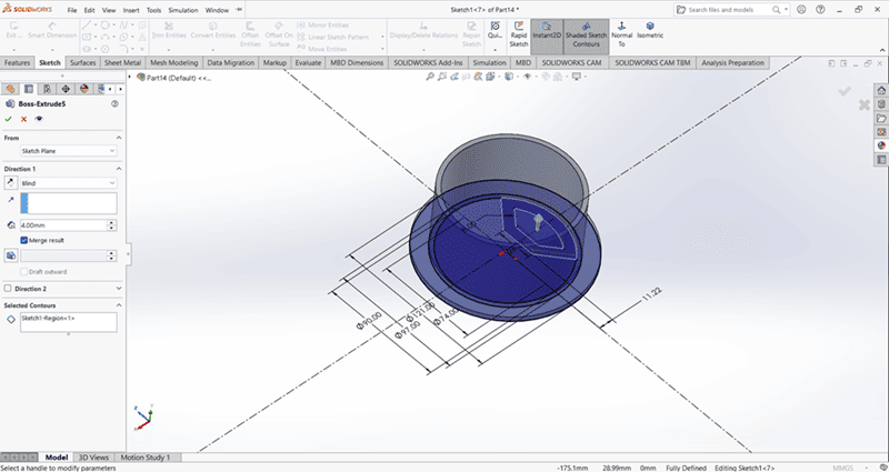
Use Extrude Boss/Base to extrude the circle to 22mm in Blind mode, ensuring the extrusion is in the reverse direction.
Select the back face for a new sketch.
Use the Circle Tool to draw a concentric circle with a diameter of 12mm, applying Smart Dimension for accuracy.
Use Extrude Boss/Base to extrude the 12mm-diameter circle to 96mm in Blind mode in the required direction.
Select the face of the 12mm diameter and draw another concentric circle with a diameter of 6mm using Circle Tool and Smart Dimension.
Use Extrude Boss/Base to extrude the 6mm-diameter circle to 12mm in Blind mode in the required direction.
To add the cosmetic thread:
Navigate to Insert > Annotations > Cosmetic Thread from the menu bar.
In the thread settings, configure the following:
Edge: Edge< 1 >
Standard: ANSI Metric
Type: Machine Thread
Size: M12 × 1.5
End Condition: Blind
Length: 90mm
Apply these settings to finalize the screw design.Once the nut is completed, save the file.
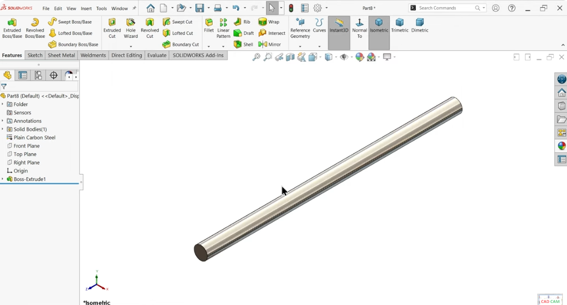
Begin by creating a new part bar:
From the File menu, select New Part to start a new drawing.
Activate the Sketch command and select the Front Plane.
Use the Circle Tool to draw a circle and set its diameter to 5mm using Smart Dimension.
Exit the sketch and navigate to the Features tab.
Activate Extrude Boss/Base, set the End Condition to Mid Plane, and extrude the circle to 96mm.
Save the file as "Bar".
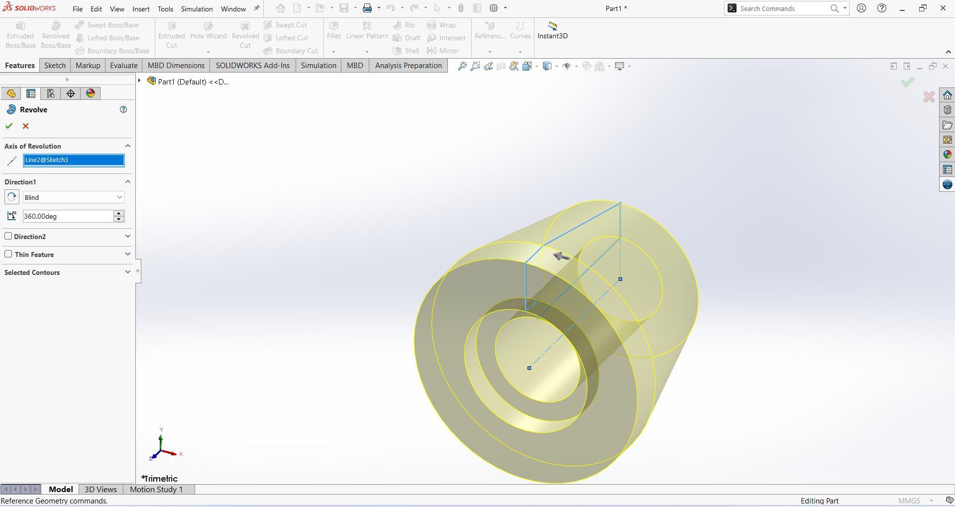
To create the bush part, follow these steps:
From the File menu, select New Part to start a new drawing.
Activate the Sketch command and select the Right Plane.
Use the Line Tool to draw a 2D shape, ensuring accuracy by applying Smart Dimension.
Exit the sketch and navigate to the Features tab.
Activate the Revolved Boss/Base feature.
In the Revolved Boss/Base settings:
Set the Axis of Revolution to the Centerline.
Choose End Condition as Blind.
Set the Angle to 360 degrees.
Click OK to complete the feature.
Save the file as "Bush".
To create the Rubber part, follow these steps:
From the File menu, select New Part to start a new drawing.
Activate the Sketch command and select the Right Plane.
Use the Line Tool to draw a 2D shape, ensuring accuracy by applying Smart Dimension.
Exit the sketch and navigate to the Features tab.
Activate the Revolved Boss/Base feature.
In the Revolved Boss/Base settings:
Set the Axis of Revolution to the Centerline.
Choose End Condition as Blind.
Set the Angle to 360 degrees.
Click OK to complete the feature.
Save the file as "Rubber".
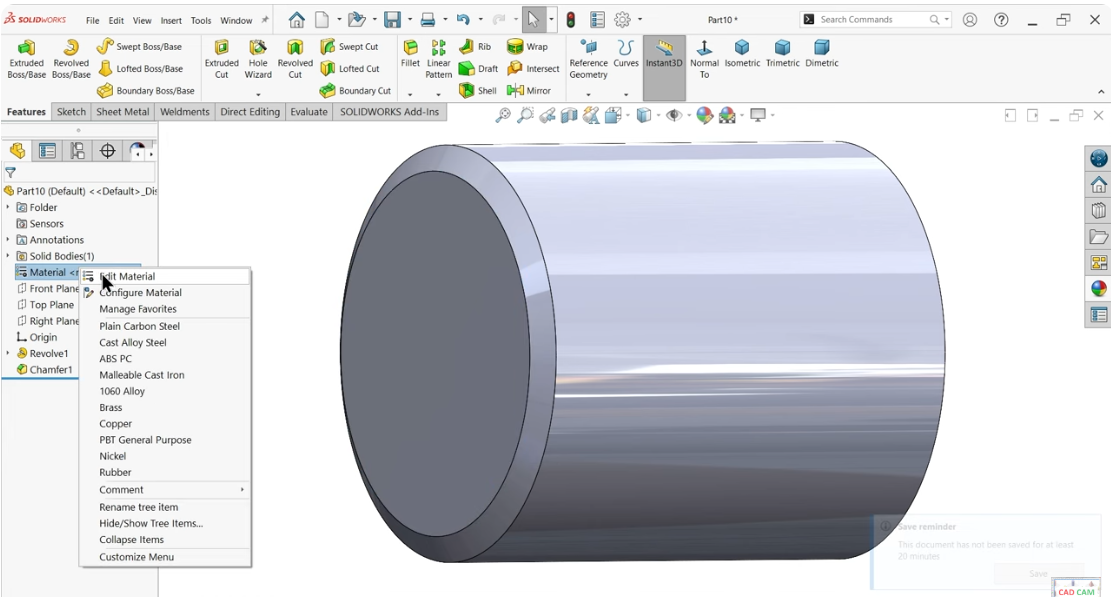
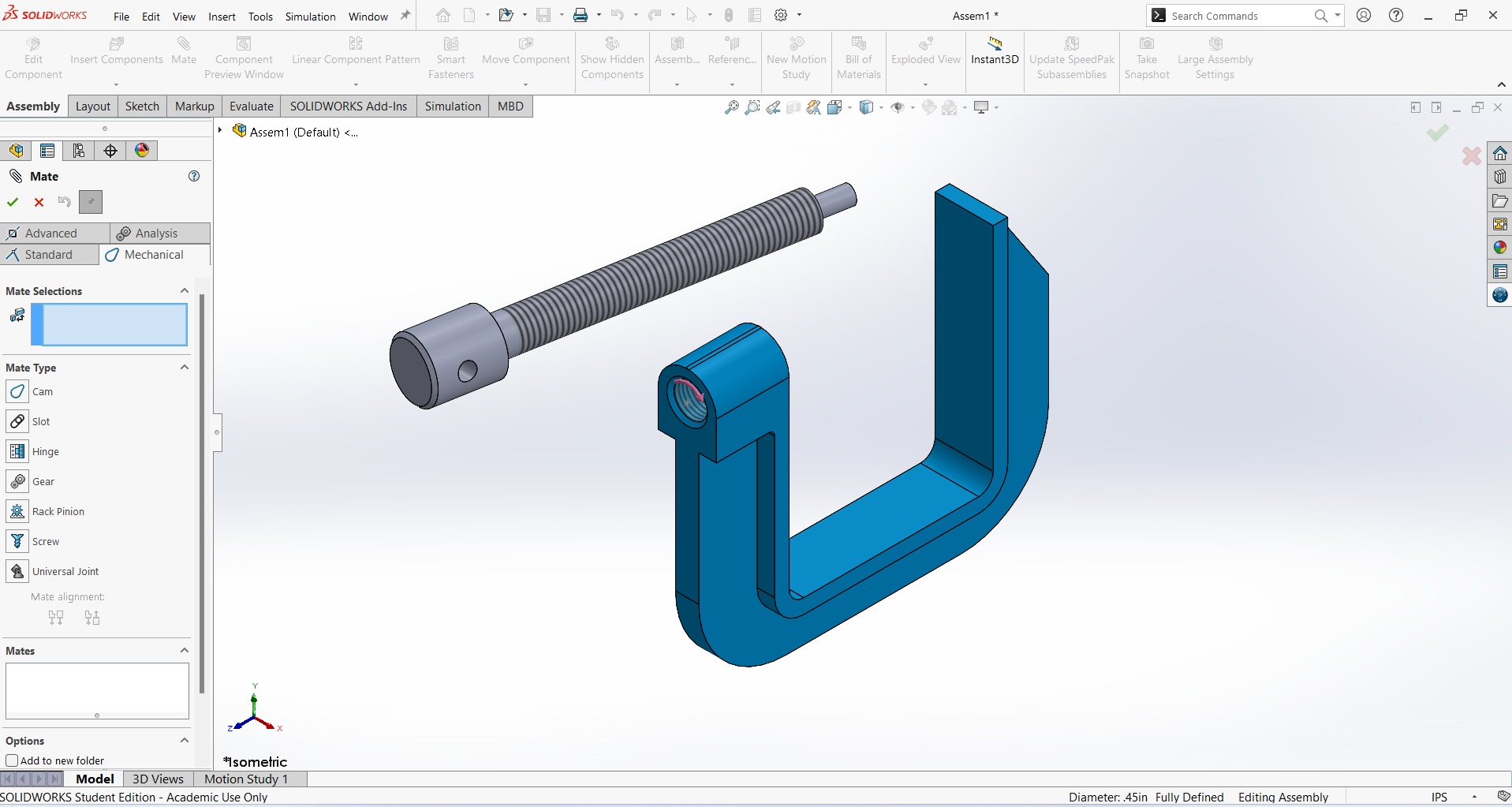
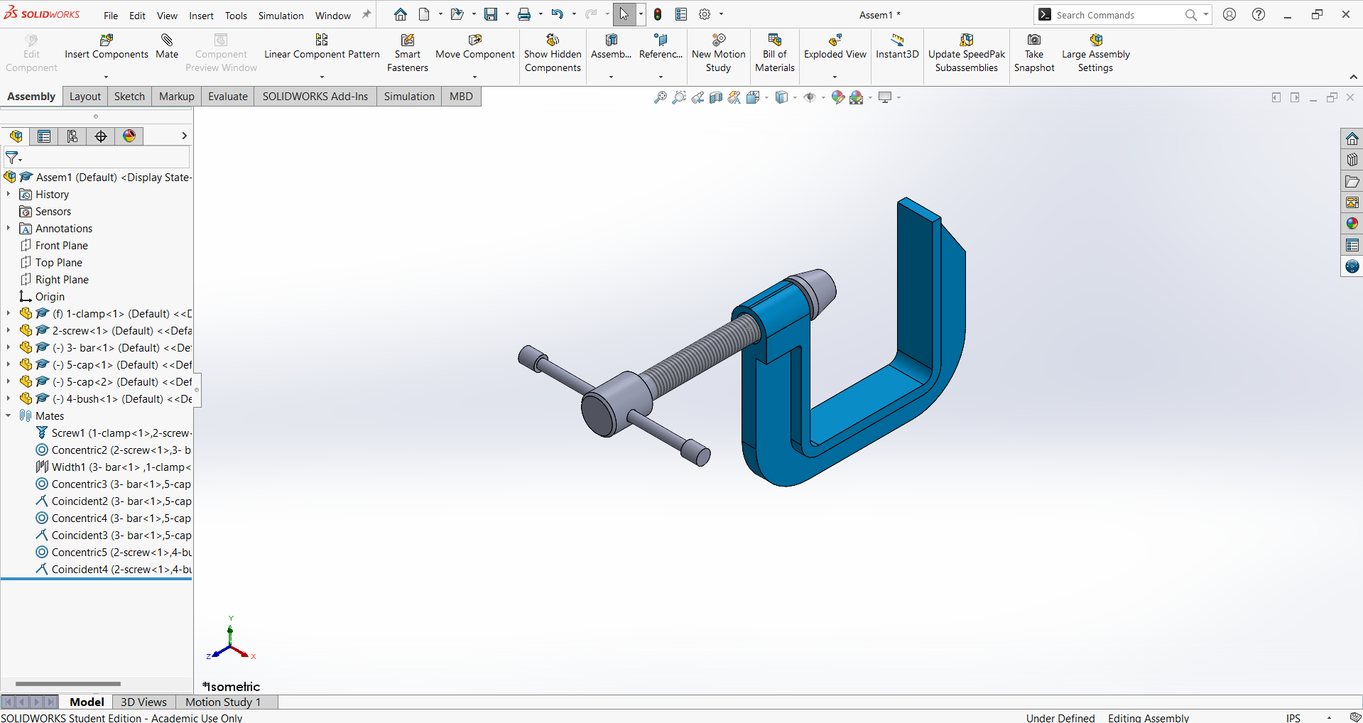
To create an assembly, follow these steps:
From the File menu, select New and choose Assembly.
Insert the first part by selecting Clamp, then click Open.
Set the Clamp in Isometric View for better visualization.
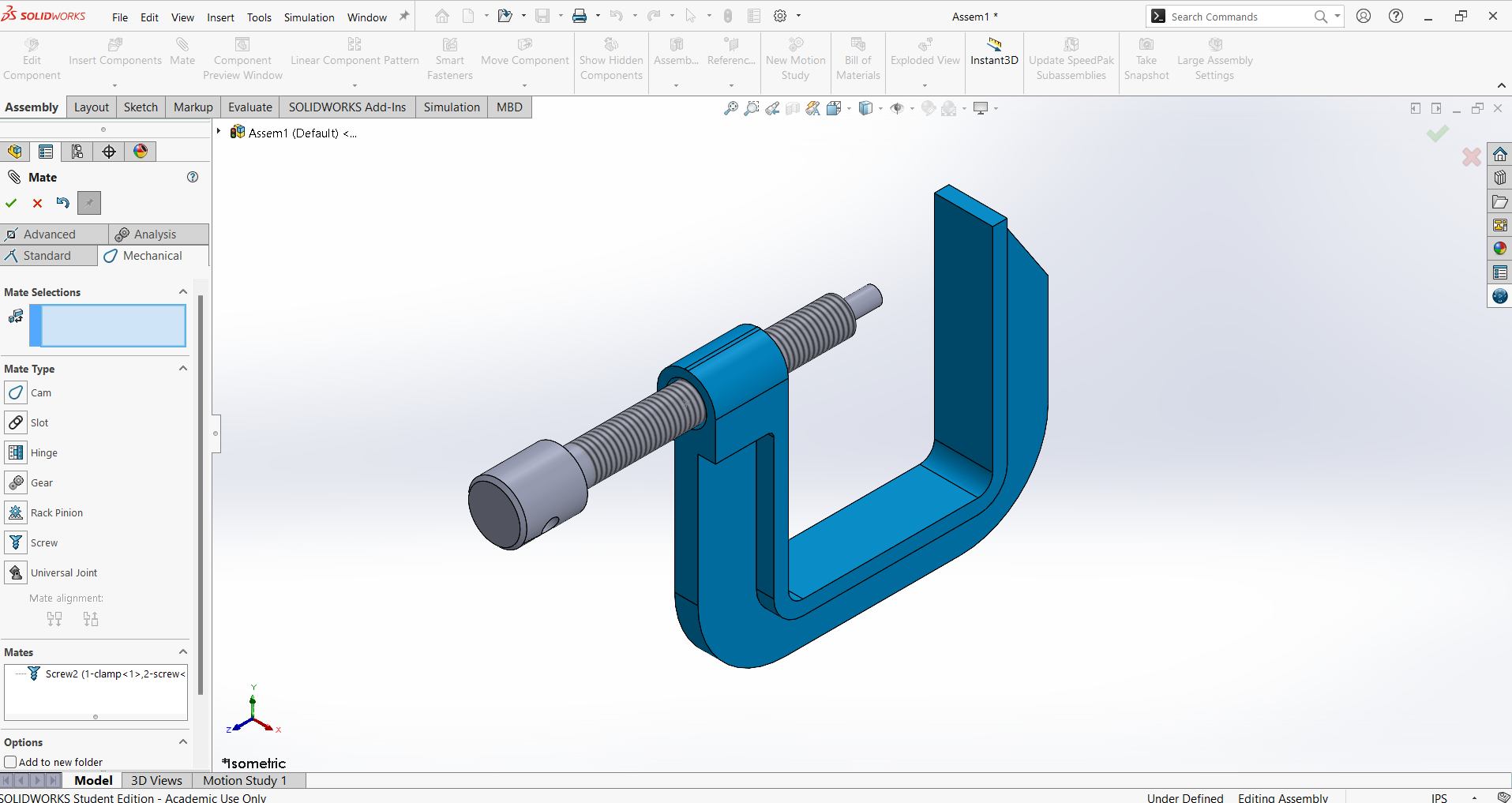
Navigate to Insert Component and select Screw, then click Open to add it to the assembly.
Go to the Mate tool and apply a Mechanical Mate.
Select the inner thread of the Clamp and the outer thread of the Screw to establish the connection.
Set the Distance/Revolution to 1.5mm, then click OK to complete the assembly.
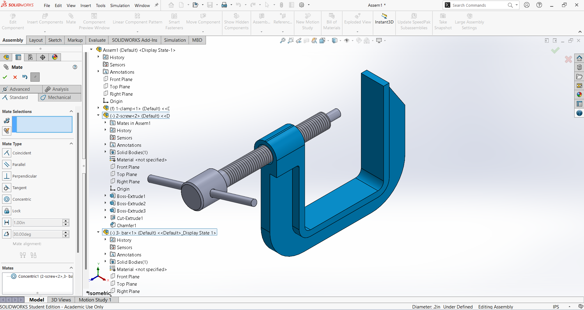
Navigate to Insert Component, select Bar, and click Open to add it to the assembly.
Rotate the Bar in the Y direction to achieve the required position.
Identify the midpoint of the Bar, where the Front Plane serves as its center.
Align the Top Plane of the Screw accurately with the Bar for proper positioning.
Select the internal surface of the Screw and the corresponding surface of the Bar, then click OK to finalize the alignment.
Navigate to Insert Component, select Rubber, and click Open to add it to the assembly.
Rotate the Rubber in the Y direction to achieve the required position.
Right-click on the Bar and select the Fix command to secure its position.
Select the internal face of the Rubber and the outer surface of the Bar, then create a Concentric relation. Click OK to confirm.
Open the Mate tool, select the internal surface of the Rubber and the side face of the Bar, then click OK to complete the alignment.
Repeat the same procedure for another side Rubber and Bush
5. Final Project Modelling
3d modeling of Robotic Arm
This week, I selected a robotic arm for my individual assignment. Since this robotic arm is a major component of my final project, its design and manufacturing using 3D printing were completed during this week.
I used SolidWorks 3D software to design the part. Using this software, I first designed the base component.
1. Base
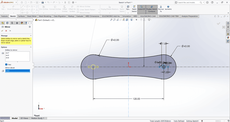
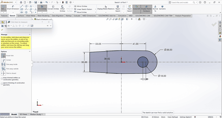
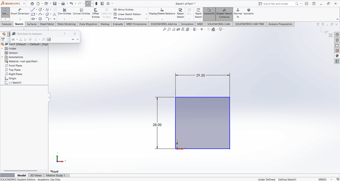
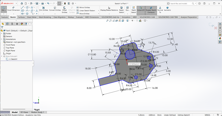
When starting the base design, I first created an accurate 2D sketch using various commands such as Circle, Trim, Line, and Rectangle.
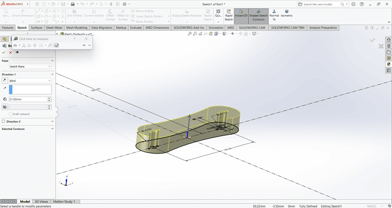
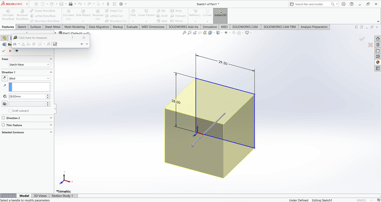
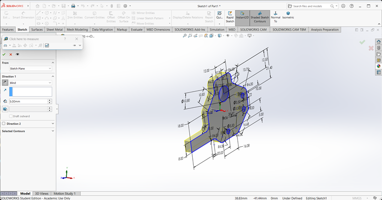
Then, I used the Extrude Boss/Base command to extend the part to the desired height
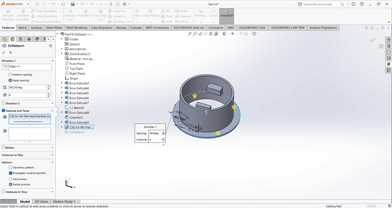
Using the Circular Pattern command, create four evenly spaced small holes along the periphery of the base.
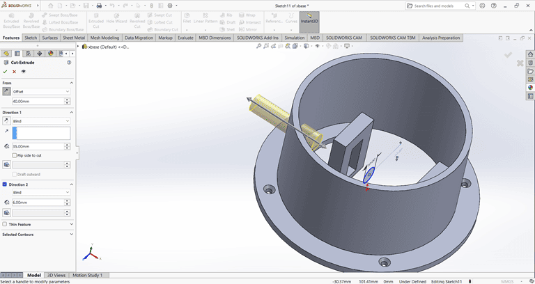
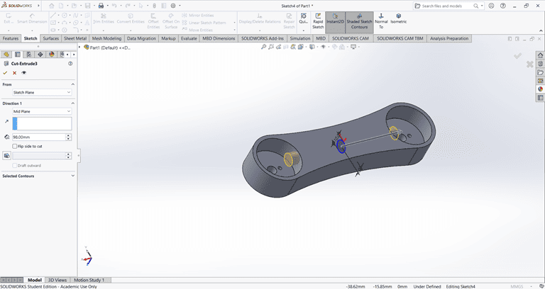
Use the Cut Extrude command to create a circular hole in the base
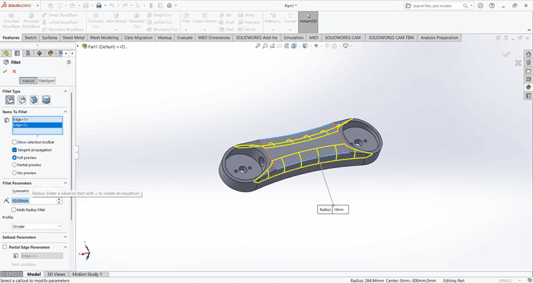
2. Arm 1
When starting the arm 1 design, I first created an accurate 2D sketch using various commands such as Circle, Trim, Line, and Rectangle.
Then, I used the Extrude Boss/Base command to extend the part to the desired height
Next, I used the Cut Extrude command to create a circular hole in the arm at the desired depth.
Then, use the Fillet command to round the edges of the rectangular shape, applying a fillet radius of 10 mm.
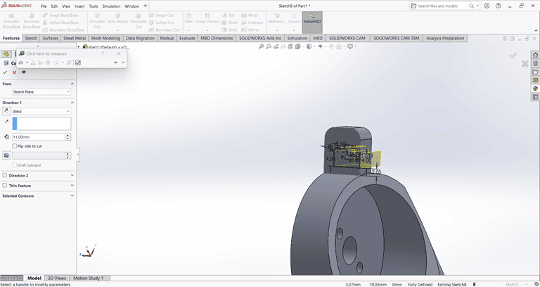
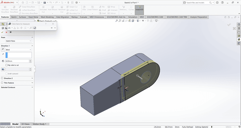
Next, create a small feature on the outer side of the arm and extrude it using the Midplane option. Then, use the Cut Extrude and Boss-Base commands to achieve the required shape.
2. Arm 2
When starting the arm 2 design, I first created an accurate 2D sketch using various commands such as Circle, Trim, Line, and Rectangle.
Then, I used the Extrude Boss/Base command to extend the part to the desired height
Next, I created a rectangle of the required dimensions on the side face. Then, I used the Cut Extrude command to create a rectangular hole through the shape.
Next, I created a circle of the required dimensions on the side face. Then, I used the Cut Extrude command to create a circular hole with the specified dimensions in the shape.
Next, I created the desired shape as shown in the figure. Then, I used the Cut Extrude command to shape it according to the specified dimensions.
Next, a rectangular shape was created on the same face where the previous Cut Extrude command was applied. Then, the Cut Extrude command was used again to cut through the entire shape.
Finally, the arm part is complete and ready for use.
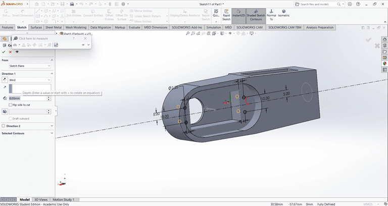
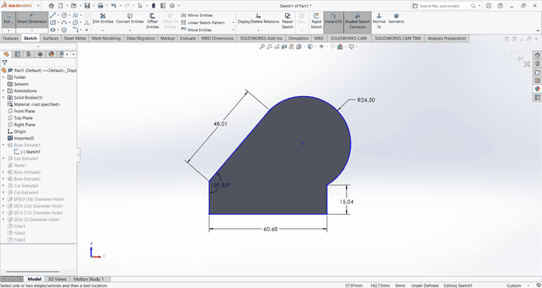
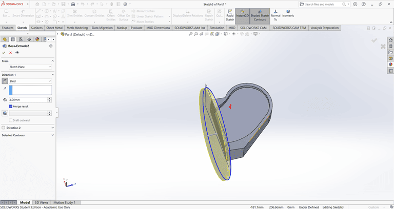
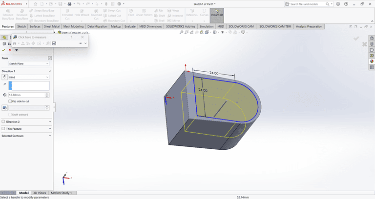
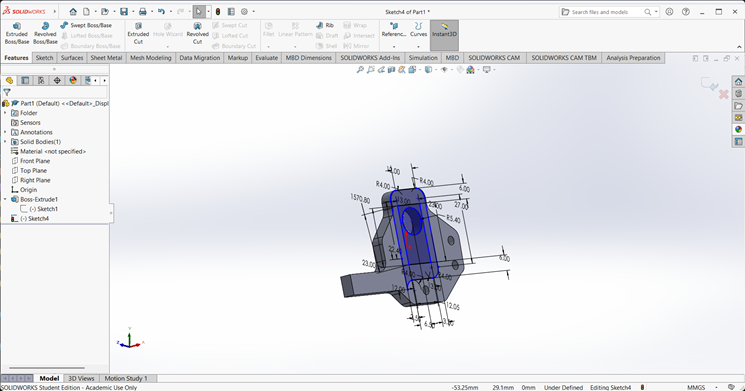
3. Base
I first created an accurate 2D sketch using various commands such as Circle, Trim, Line, and Rectangle.
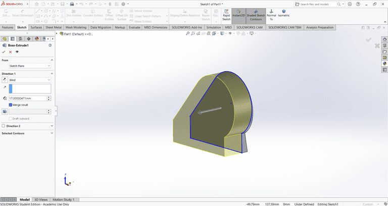
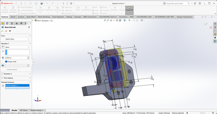
Then, I used the Extrude Boss/Base command to extend the part to the desired width.
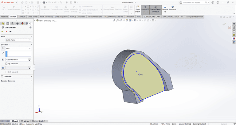
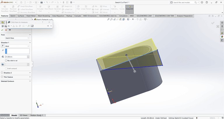
Next, I sketched the required shape on the front face to perform the cut operation.
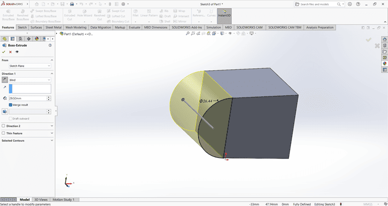
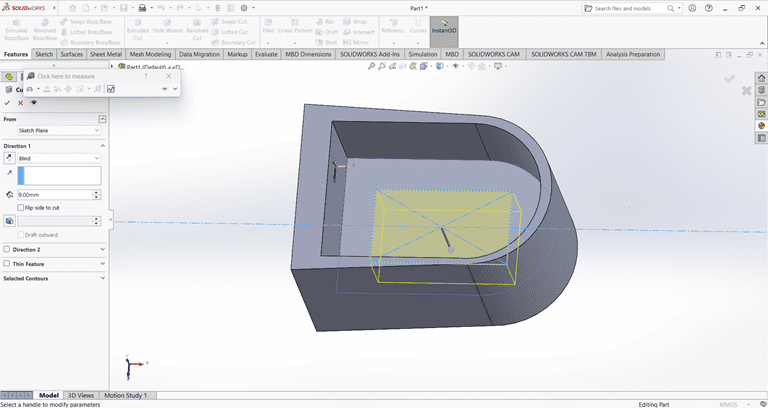
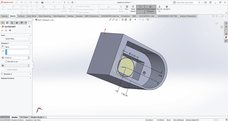
Next, on the bottom face, I first located the center point and then used the Circle command to draw a circle. After that, I applied the Extrude Boss/Base command to create the base.
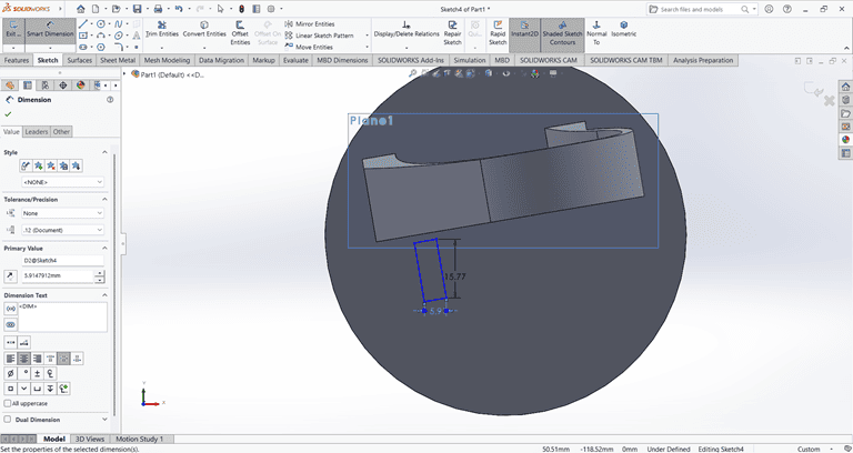
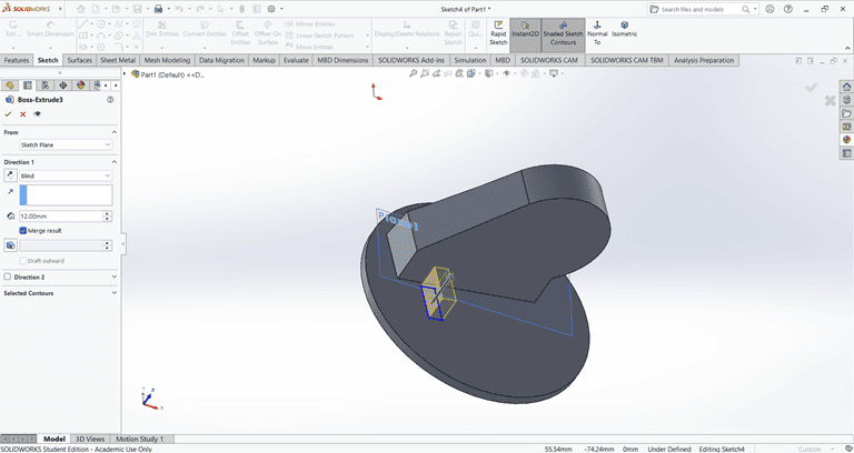
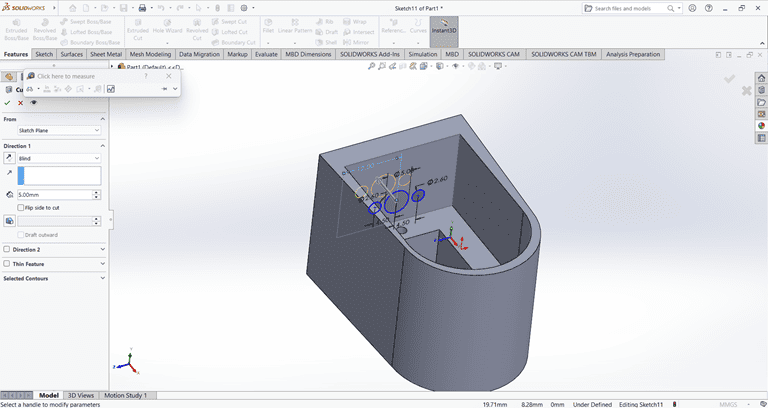
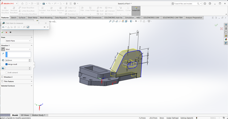
Next, I selected the top face and drew a rectangle at the specified location. Then, I applied the Extrude Boss/Base command. After that, I selected the side face of the rectangle and used the Cut Extrude command to create a rectangular hole.
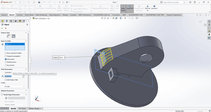
Next, I applied the Fillet command to the small rectangle with a fillet radius of 3 mm.
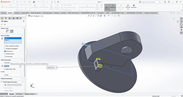
Next, I applied the Fillet command to the main shape with a fillet radius of 20 mm.
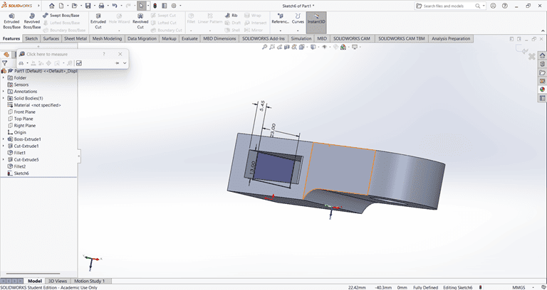
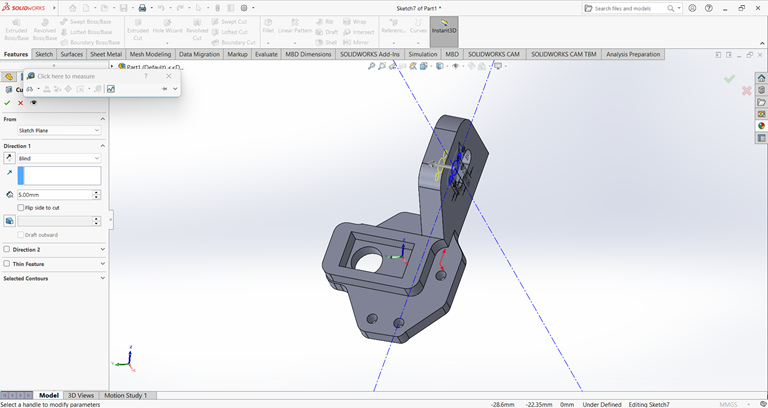
4. Joint
I first created an accurate 2D sketch using various commands such as Circle, Trim, Line, and Rectangle.
Then, I used the Extrude Boss/Base command to extend the part to the desired width.
Next, I created a half-circle on the top of the rectangle.
I created a precise 2D sketch using various commands such as Circle, Trim, Line, and Rectangle.
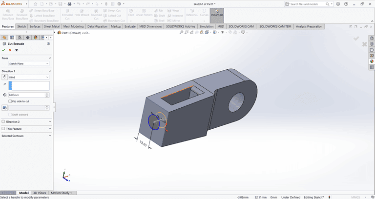
Next, I used the Cut Extrude command to remove that part. Then, on the same face, I sketched a rectangle to be cut in the next step.
Next, on the same face, I used the Circle command to draw a circle with the specified dimensions.
Next, on the bottom side, I used the Circle command to draw a circle with the specified dimensions. Then, I applied the Cut Extrude command to remove that shape.
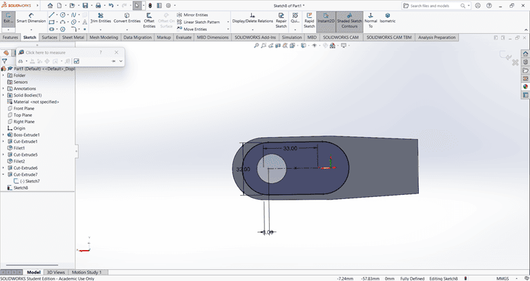
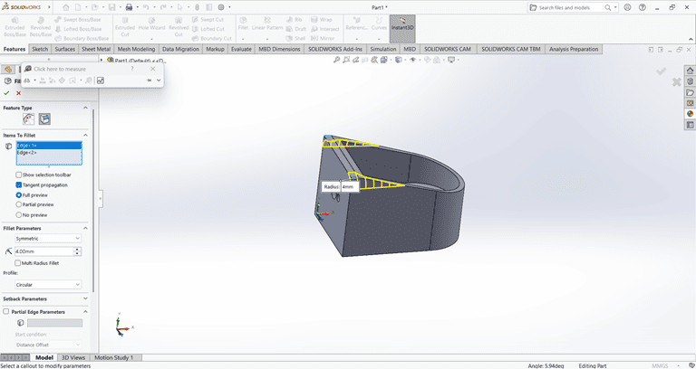
Next, I drew a triangle on the side face using the Line and Dimension commands. Then, I applied the Cut Extrude command to create a slanted edge.
then on that slant edge apply the fillet command of 4mm to edge make circular.
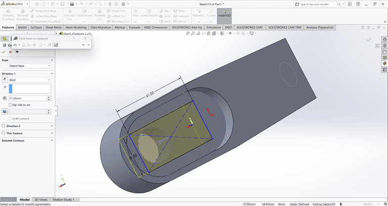
5. Clip
I first created an accurate 2D sketch using various commands such as Circle, Trim, Line, Dimension and Rectangle.
Then, I used the Extrude Boss/Base command to extend the part to the desired width.
Next, on the front face of the extruded part, I created a 2D sketch of the desired shape for extrusion.
I extruded that part upward to the desired height.
On the side face, I created a 2D sketch and extruded it to a width of 8 mm.
Finally, the clip part is complete and ready.
6. Gear
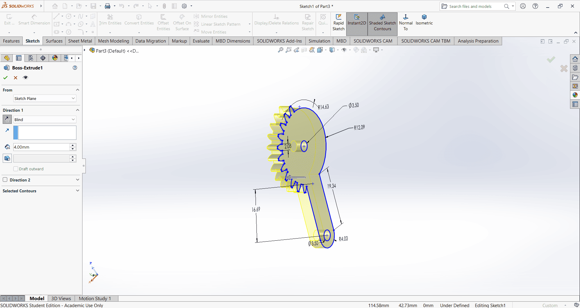
I first created an accurate 2D sketch using various commands such as Circle, Trim, Line, Dimension and Rectangle.
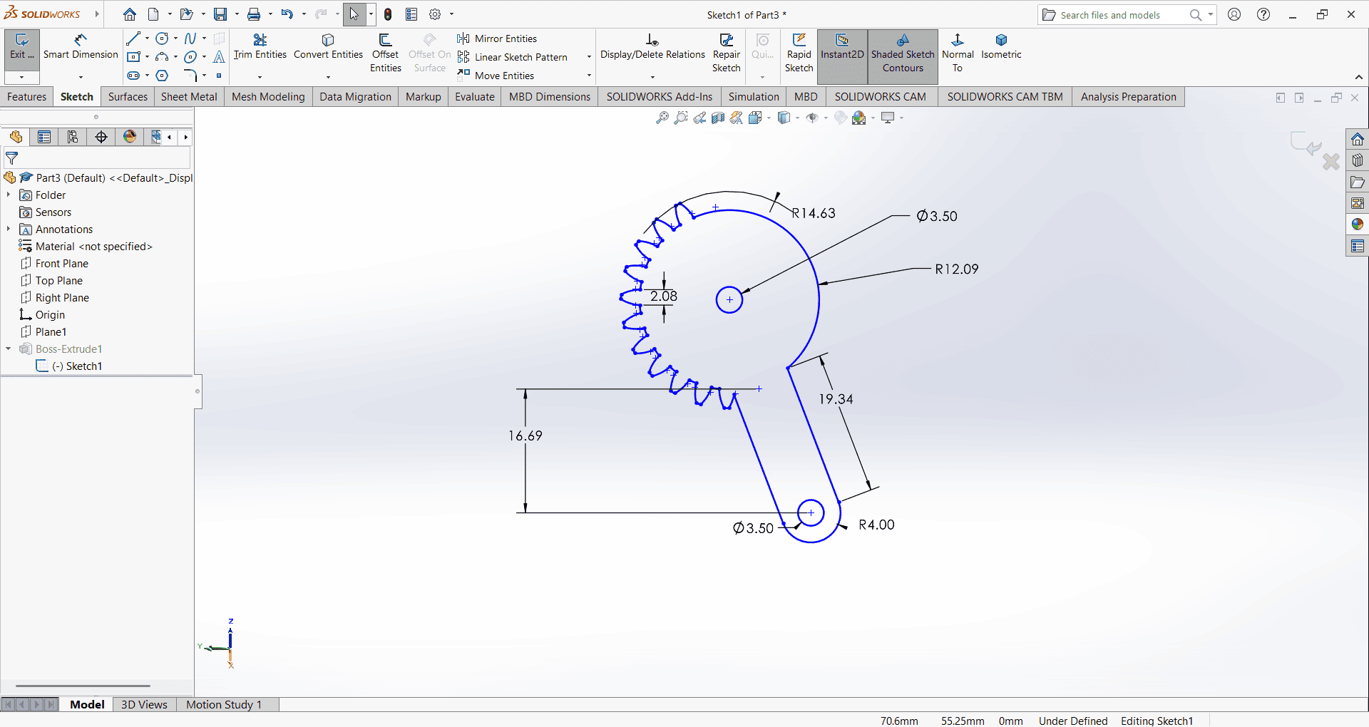
Then, I used the Extrude Boss/Base command to extend the part to the desired height.
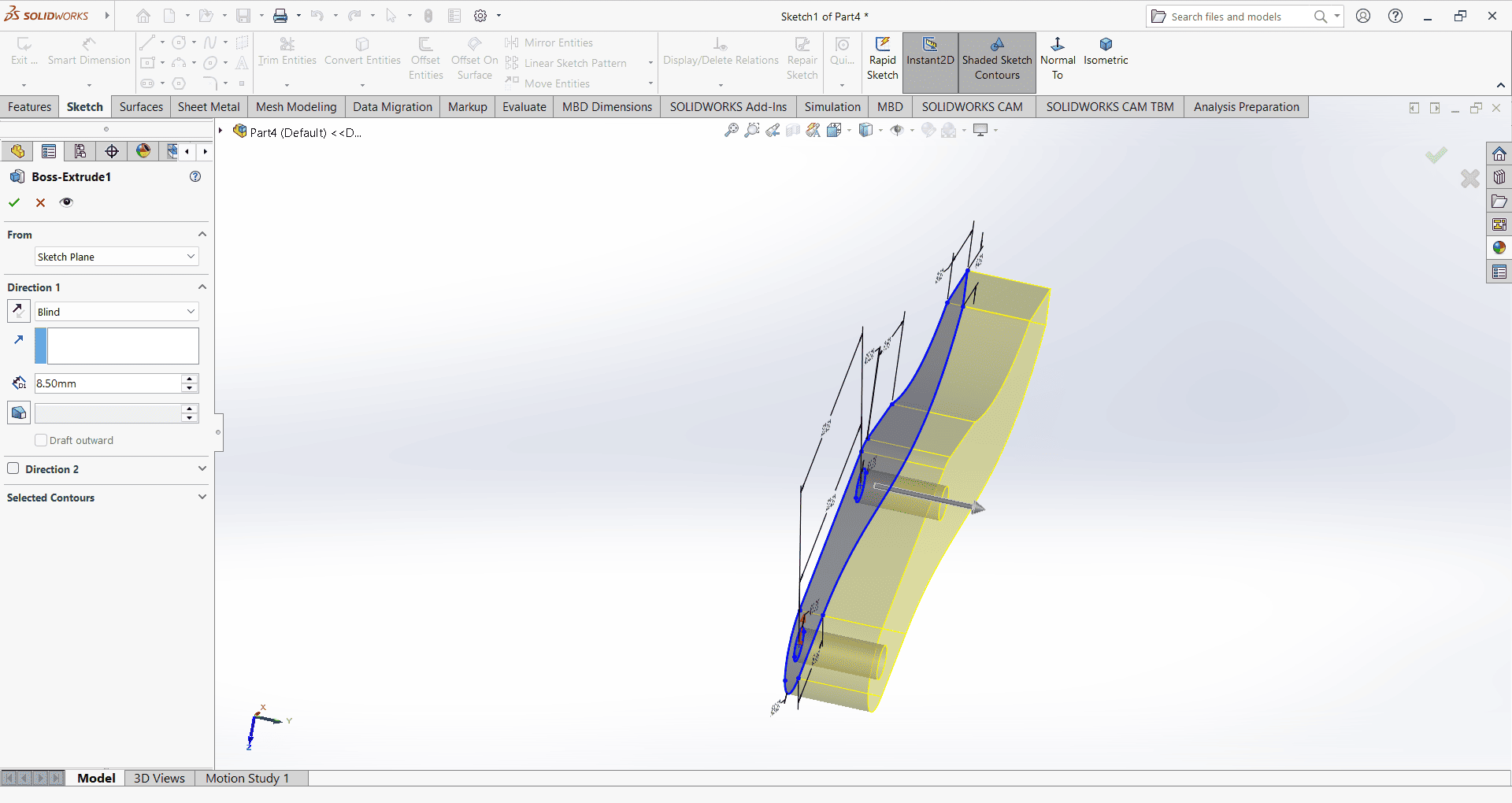
7. Gripper
I first created an accurate 2D sketch using various commands such as Circle, Trim, Line, Dimension and Rectangle.
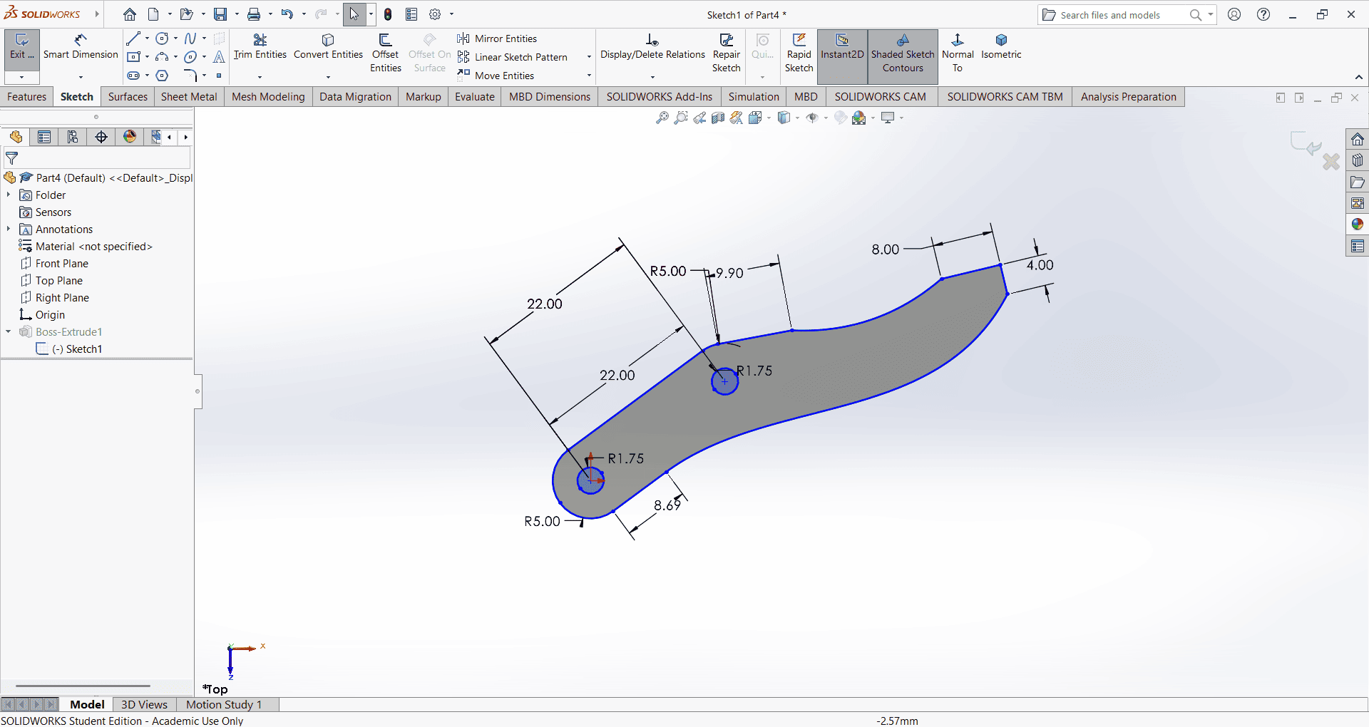
Then, I used the Extrude Boss/Base command to extend the part to the desired height.
8. Pin
I first created an accurate 2D sketch using various commands such as Circle, Trim, Line, Dimension and Rectangle.
Then, I used the Extrude Boss/Base command to extend the part to the desired height.