WEEK 13
Molding and Casting
This week, I will be exploring the process of molding and casting through a hands-on project. The objective is to design and fabricate a replica of the Avengers logo using SolidWorks and a series of manufacturing steps.
The project will begin with the digital design of the Avengers logo in SolidWorks, where I will create a detailed 3D model. From this model, I will design a mold cavity that represents the negative form of the logo. Once the negative mold is complete, it will be 3D printed to produce a physical mold cavity suitable for casting.
After printing the mold, I will prepare the casting material—such as resin, silicone, or plaster—depending on the desired finish and properties of the final piece. This material will be poured into the 3D-printed mold cavity to form a positive replica of the Avengers logo.
The process will conclude with the demolding of the cast, resulting in a solid, positive representation of the original design. This project will provide practical experience in CAD modeling, mold design, additive manufacturing, and casting techniques.
Group Assignment
As part of our molding and casting module, Dr. Sujit and I collaborated on a group assignment aimed at gaining practical knowledge of material handling and mold-making techniques through comparative analysis and experimentation.
Objectives
1. To understand the chemical properties and safety measures associated with various molding and casting materials through the review of their Safety Data Sheets (SDS).
2. To perform and evaluate test casts using different materials to observe their behavior, finish quality, and curing characteristics.
3. To compare different mold-making processes in terms of accuracy, ease of use, and material compatibility.
4. To develop hands-on experience in safe handling, preparation, and application of molding and casting techniques.
The group assignment is linked here
Individual Assignment
In this individual assignment, I undertook the task of designing and fabricating a mold suitable for casting a specific part. The focus was on developing a mold that aligns with the chosen casting process, ensuring precision, ease of demolding, and material compatibility. A key requirement was to produce a mold with a smooth surface finish, free from visible toolpaths or manufacturing marks, to enhance the final cast quality. The completed mold was then used to create cast parts, validating the design and production approach.
Objectives
1. To design a mold optimized for a specific casting process using CAD tools.
2. To fabricate the mold with a high-quality surface finish that does not display the toolpath marks.
3. To apply the mold in a real casting process and produce accurate and detailed cast parts.
4. To gain hands-on experience in mold design, surface finishing, and casting techniques.
Moulding
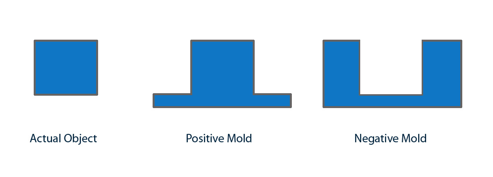
The molding process involves creating a mold that serves as a cavity into which a casting material is poured to form a desired shape. In this assignment, both positive and negative molds were used to replicate the designed object
1. Negative Mold
A negative mold represents the hollow cavity or inverse of the final object. It is typically created based on a 3D model of the part using CAD software such as SolidWorks. For this project, the negative mold of the Gear was designed and 3D printed with precise dimensions and smooth surfaces to ensure a clean cast. This mold acts as the container for the casting material and defines the external shape of the final
2. Positive Mold
The positive mold is the result of pouring the casting material—such as resin, silicone, or plaster—into the negative mold. After curing and hardening, the cast is removed to reveal the positive form of the original design. This part is an exact replica of the intended shape, capturing fine details and surface textures defined by the negative mold.
Using this method, the molding process effectively translates a digital design into a physical part by using the negative mold as a template to produce a positive final product. This hands-on approach enhances understanding of part geometry, material behavior, and the importance of mold surface quality.
3d modeling of Gear
The primary focus of this assignment is gear manufacturing, for which generating an accurate negative mold is a critical step. Creating a precise negative mold ensures that the final cast gear maintains the required dimensions, tooth profile, and surface quality essential for proper functionality.
I used SolidWorks software to design the negative mold for the gear, ensuring precise dimensions and accurate geometry suitable for the casting process.
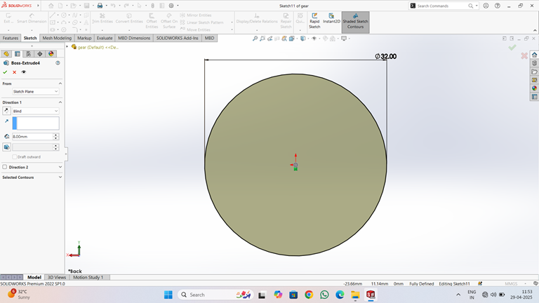
When starting the gear negative mold design, I first created an accurate 2D sketch using commands such as Circle of diameter 32mm.
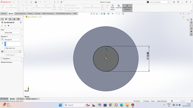
Using the same Circle command, draw another circle with the same center and a diameter of 12.5 mm.
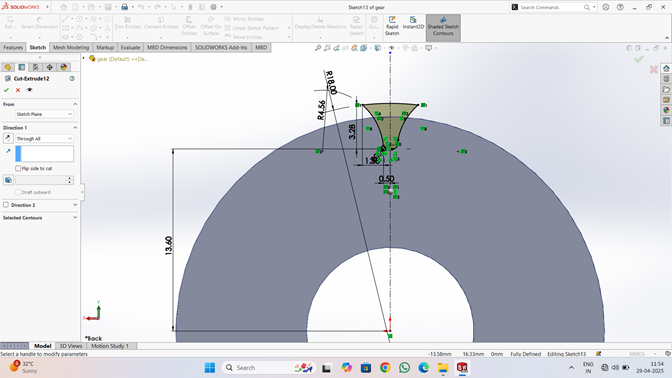
The gear tooth profile is constructed on a circular base with an outer diameter of approximately 38.40 mm and an inner diameter circle defined earlier. A tooth segment is sketched by revolving a profile about the center axis.
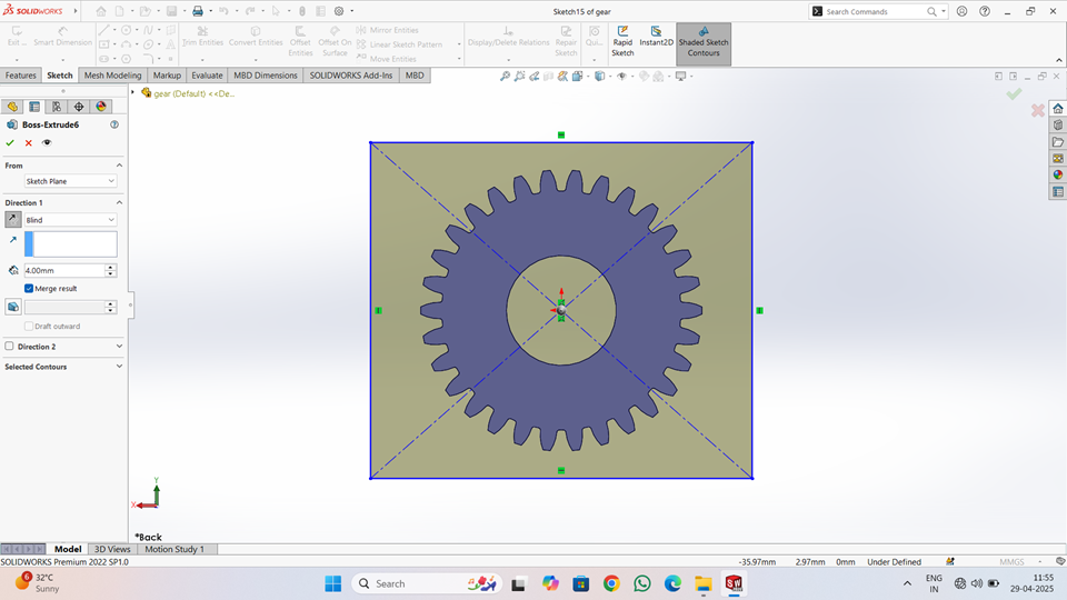
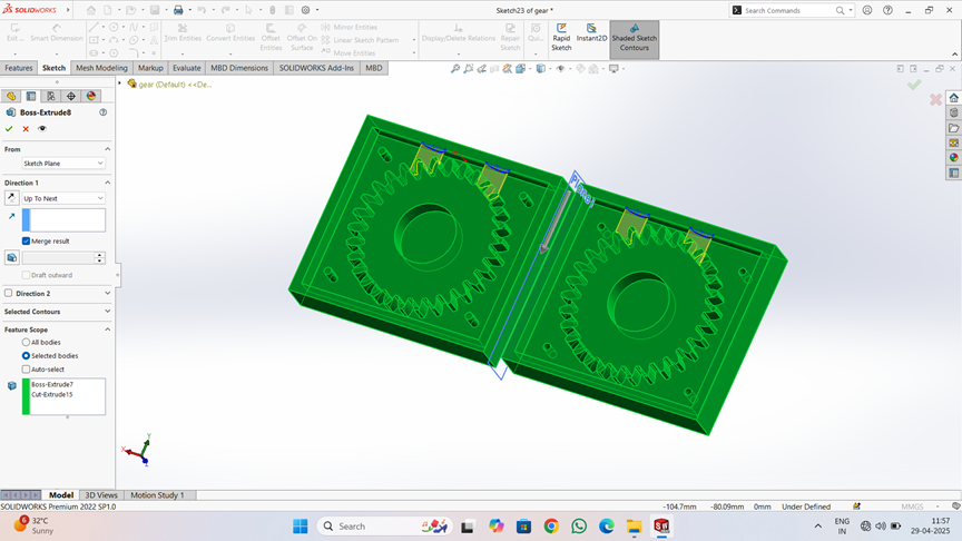
The 3D model of a spur gear designed using the Boss-Extrude feature. The gear profile has been sketched accurately with multiple uniformly spaced teeth and a central bore for shaft mounting. The extrusion is performed in the "Blind" direction with a depth of 4.00 mm, resulting in a solid gear body. Diagonal construction lines and a square boundary in the sketch indicate that the gear is centered within a reference frame to ensure symmetry and alignment. The "Merge result" option is enabled, meaning the extrusion will be merged with any existing geometry to form a single solid body.
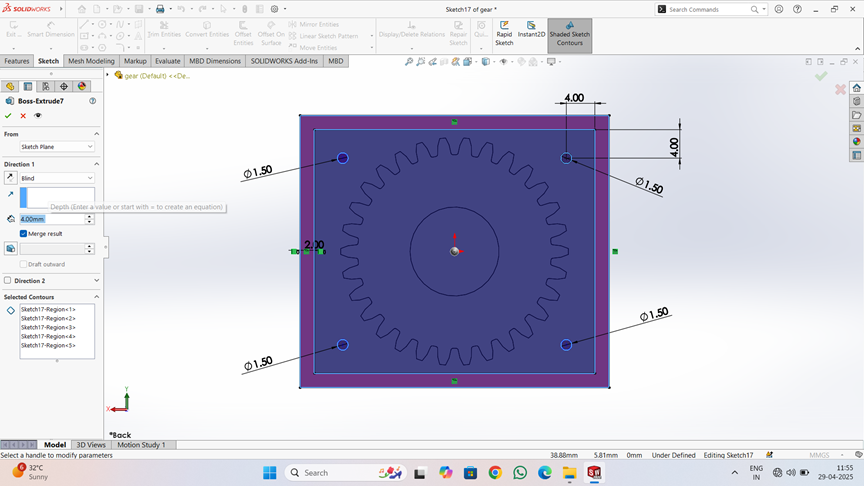
Four circular holes, each with a diameter of 1.50 mm, positioned at the corners of the base.These holes are dimensioned precisely, with their distances from the edges set to 4.00 mm, ensuring uniform placement and alignment. The extrusion depth is set to 4.00 mm, creating a solid structure. The "Merge result" option is enabled to combine all features into a single solid body.
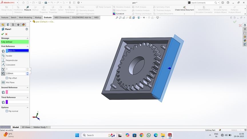
The figure illustrates a 3D assembly setup in SOLIDWORKS, where a spur gear is enclosed within a box, likely representing a mold or housing. The highlighted blue component appears to be a cover plate or mating surface, aligned using a plane feature (Plane1) created at a 20.00 mm offset from the base reference (face < 1 >). The mate references are fully defined, ensuring accurate positioning in the assembly.
The figure shows the use of the Mirror feature in SOLIDWORKS to create a symmetrical copy of the gear housing using Plane1 as the mirror plane.
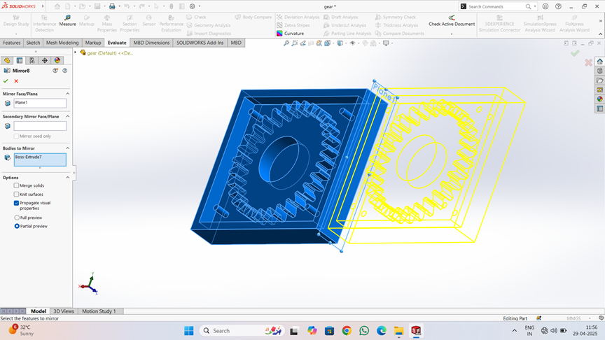
The two mirrored halves, each containing a gear cavity, are joined side-by-side, forming a closed mold structure.
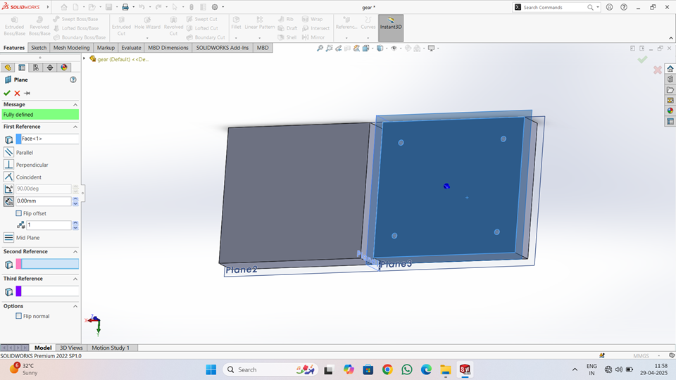
The image shows the creation of a reference plane in SOLIDWORKS. A new plane (Plane3) is defined at a 90° angle to an existing face (Face<1>).
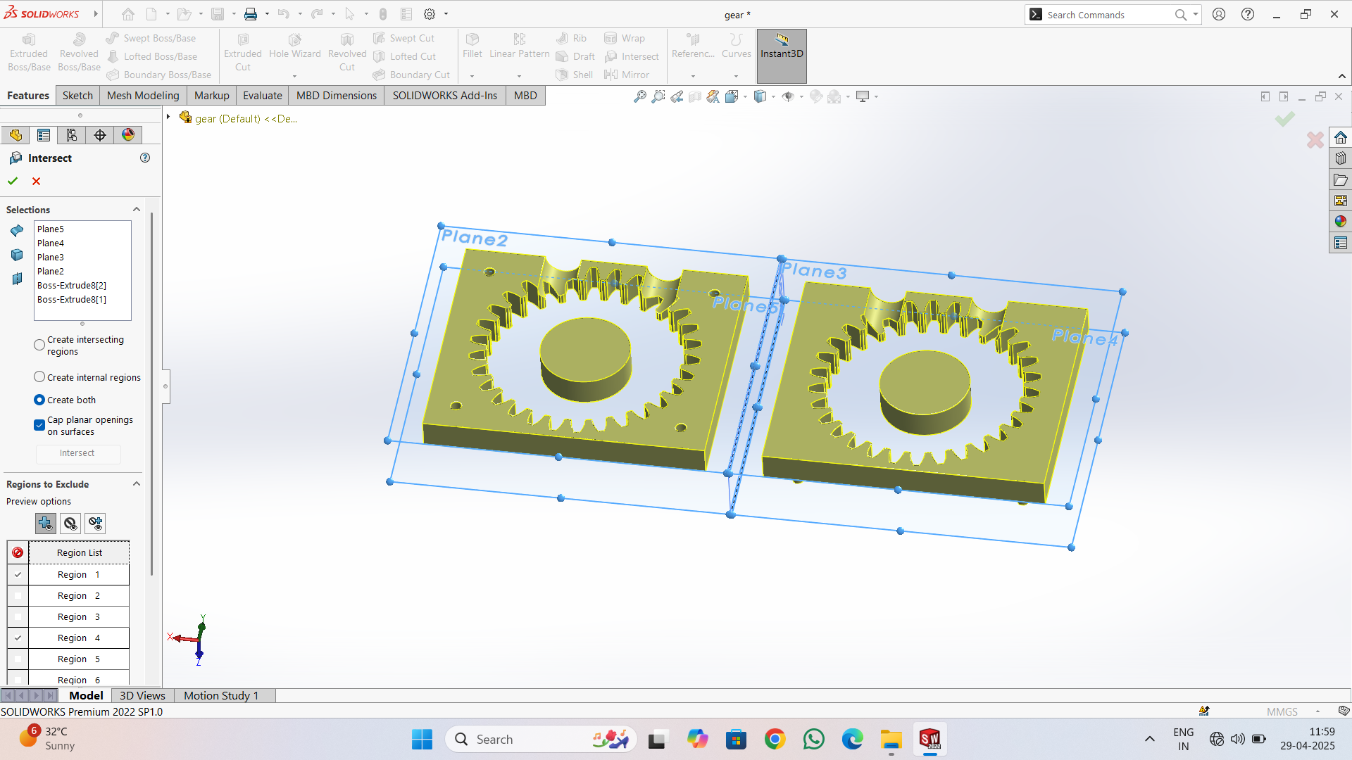
use of the Intersect command in SOLIDWORKS, where two gear-like parts are placed side by side and intersected using multiple reference planes (Plane2, Plane3, Plane4, and Plane5). The selected planes cut through the model, creating multiple regions that can be individually managed. The option "Create both" is selected, meaning both internal and external regions are generated. Each region is listed in the "Regions to Exclude" section, allowing control over which parts of the geometry to keep or remove.
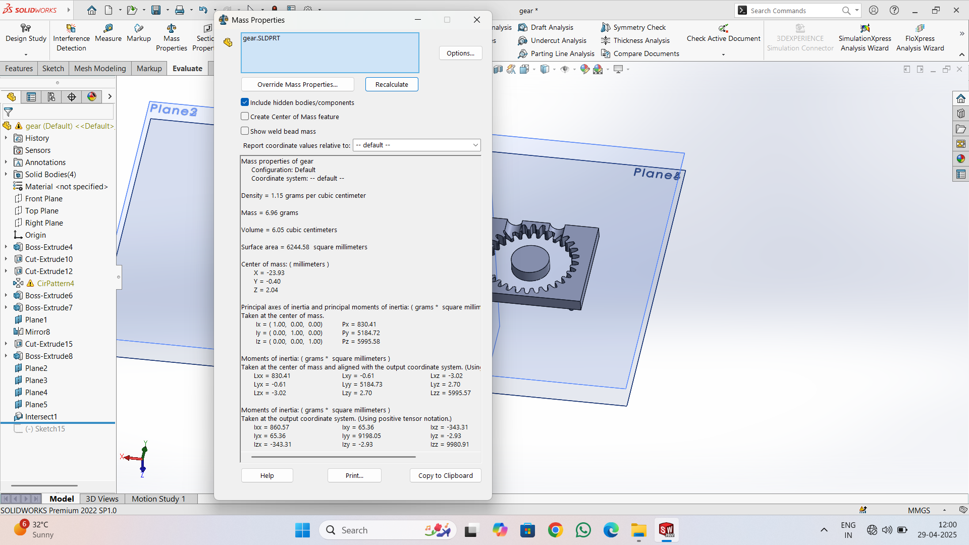
Mass Properties provides detailed physical information about the model, such as mass, volume, surface area, center of mass, and moments of inertia. The mass is calculated as 6.96 grams, with a volume of 6.05 cubic centimeters and surface area of 6244.58 mm². The center of mass coordinates are also listed, helping in balancing and assembly.
Slicing
First, I downloaded the STL files in solid works for gear to generate their G-codes. We then imported all STL file into the Ultimate cura slicing software to generate the G-code required for the 3D printer.
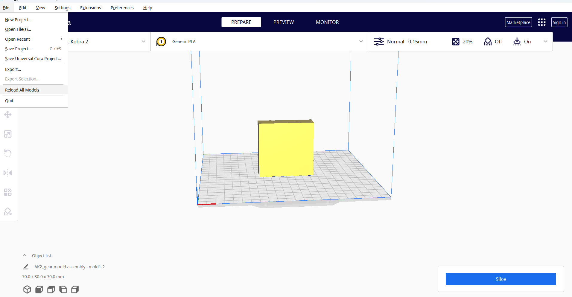
I opened the Ultimaker Cura software and navigated to the File menu. Then, I selected the Import option and chose the previously saved files in STL format.
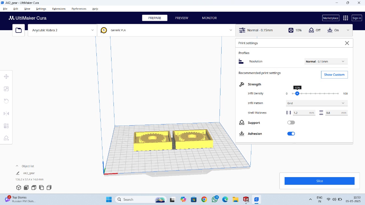
Then, right-click and select "Arrange All Models" to automatically arrange all models in a specific layout. Next, navigate to the print settings and select the "Normal 0.15mm" profile. Set the layer height to 0.2 mm, and configure additional parameters such as infill density, infill pattern, print temperature, build plate temperature, print speed, support structure and material settings as required.
After selecting all the parameters, click "Slice." Once the processing is complete, the required printing time will be displayed.
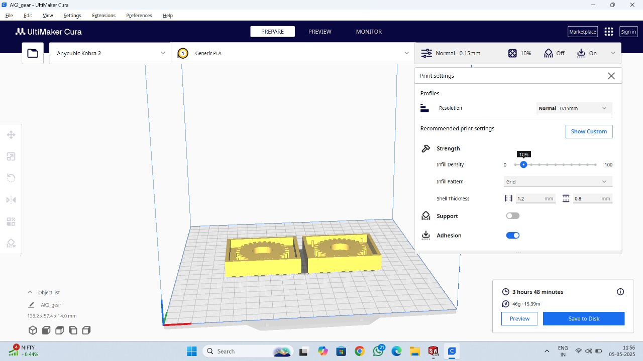
Finally, save the file to a memory card.
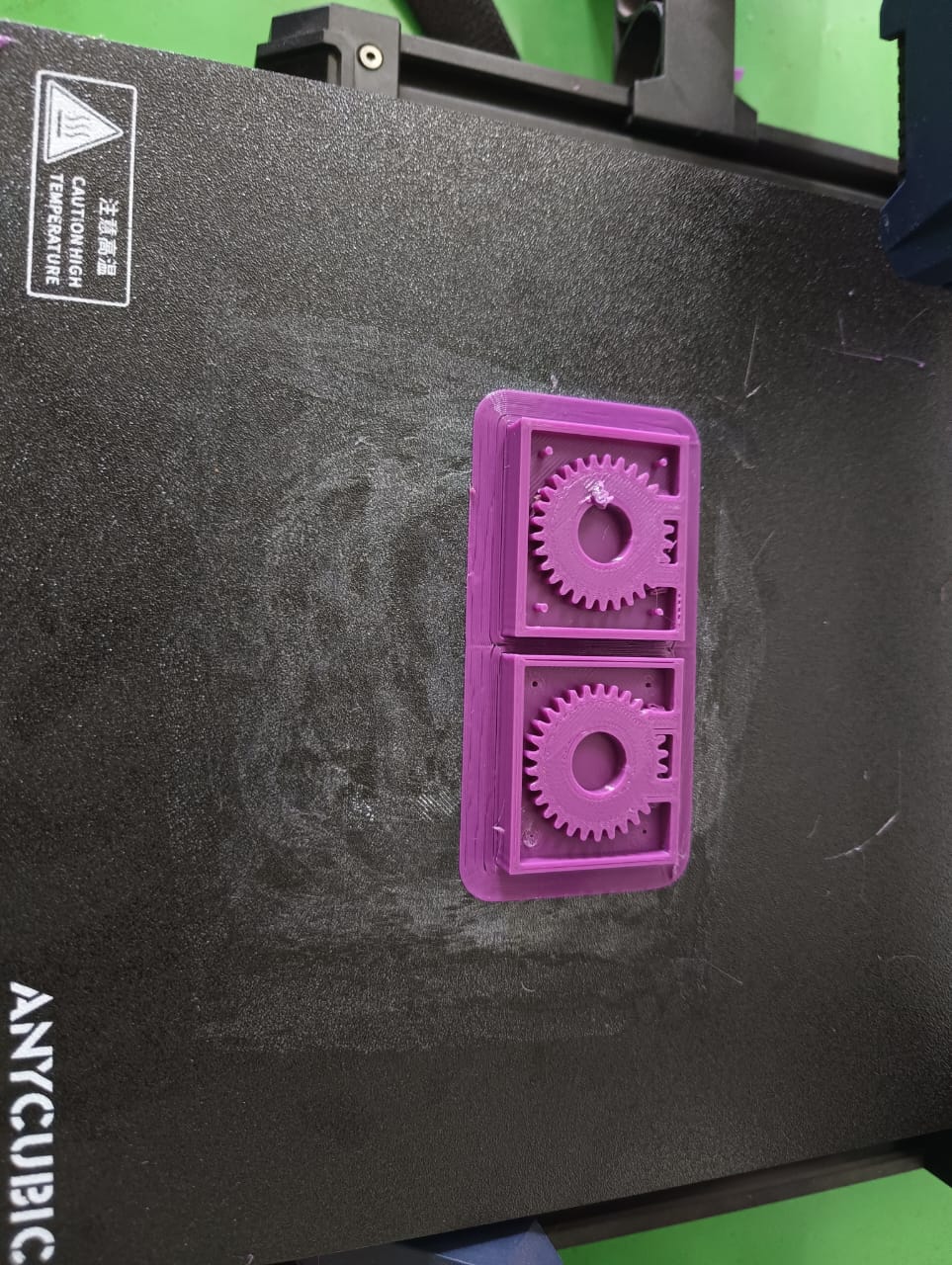
Printing
After setting up our 3D printer with Nozzle temperature as 200 deg C and bed temperature as 70 deg C.
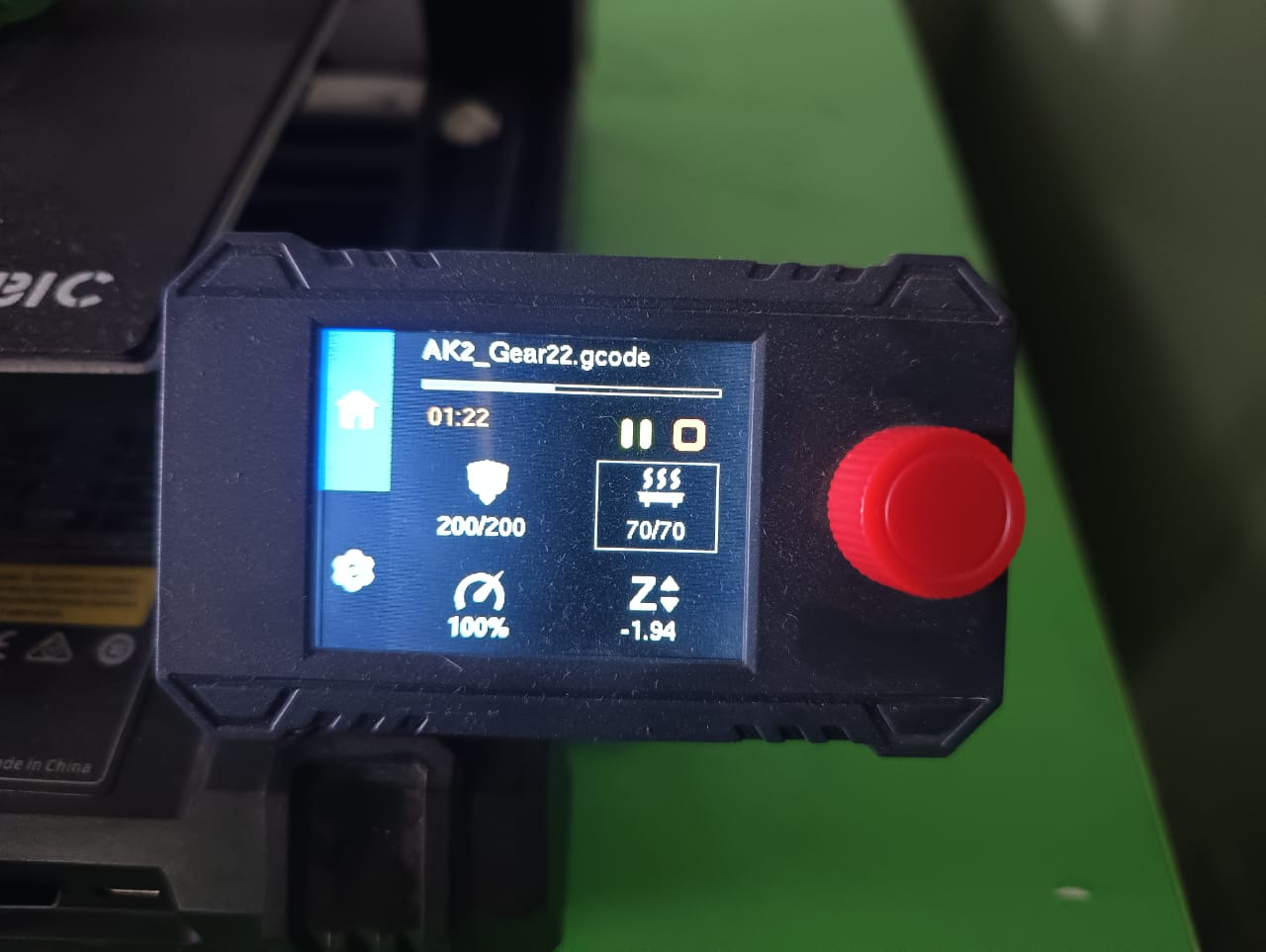
Next, I selected the file from the memory card inserted into the machine and started the printing process.
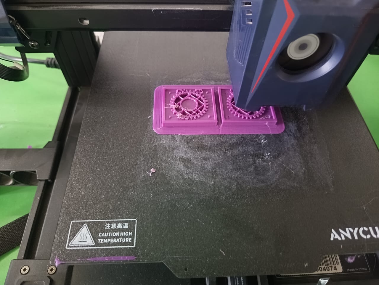
Finally, our part was successfully printed and ready for use.
Negative mold-making
After that I mixed the both silicon rubber chemicals for that I mixed that i 1:20 ratio(for 1gm of catalyst 20gm silicon rubber)
I divided 6.96 grams(Calculated in Solidworks) into a 1:20 ratio. Below is the breakdown:
Catalyst : Weight 0.3314 grams
Silicon Rubber : Weight 6.628 grams
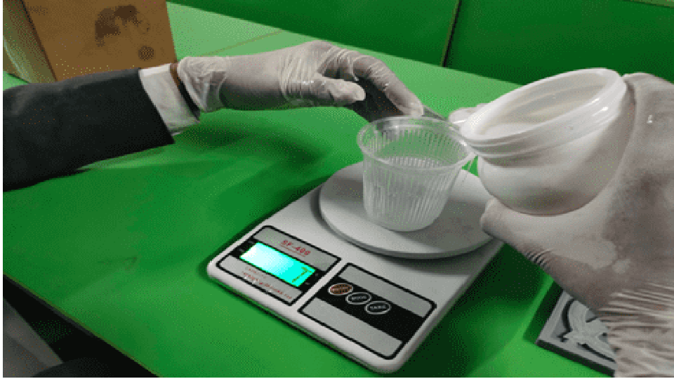
I carefully prepared a mixture by weighing out 6.96 grams, which corresponds to a 1:20 ratio—meaning approximately 0.33 grams of solute mixed with 6.63 grams of solvent. After thoroughly combining the two components to achieve a fine, uniform mixture, I ensured there were no clumps or uneven particles. Once the mixture was fully blended, I poured it carefully into the 3D-printed part, making sure it spread evenly and filled the intended spaces without trapping air bubbles
After mixing the components thoroughly to achieve a fine and uniform consistency, I made sure to remove all air bubbles from the mixture to ensure a high-quality mold without defects. Once the mixture was bubble-free, I carefully poured it into the 3D-printed part, ensuring it filled the mold cavity completely and evenly. I then allowed the mold to cure undisturbed for 24 hours. After the curing process was complete, I gently removed the hardened mold cavity from the 3D-printed part, successfully obtaining the final output as intended.
Positive mold-making
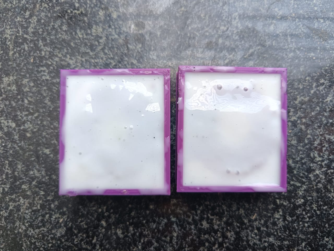
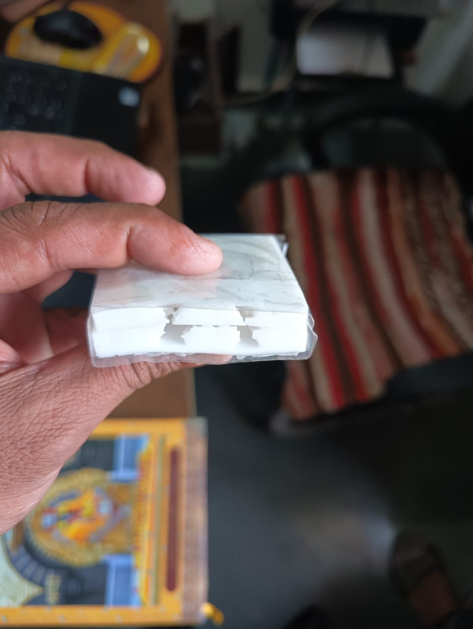
To prepare the mold for pouring, I carefully covered the cavity using transparent tape to seal the base and prevent any leakage. Once secured, I slowly poured the mixed epoxy resin into the mold cavity, making sure it filled completely and settled evenly without trapping air bubbles. This step was crucial to ensure a clean, high-quality final casting with a smooth finish.
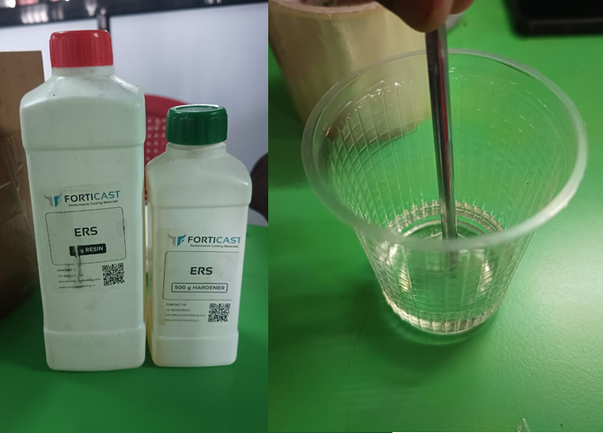
I measured 30 grams of ERS resin and 15 grams of ERS hardener, following the required 1:2 ratio (resin to hardener). I carefully combined the two components and stirred them thoroughly to achieve a smooth, uniform mixture, ensuring that the resin and hardener were fully integrated for proper curing. This precise mixing process was essential to achieve the desired material strength, clarity, and finish in the final cast. Once mixed, the epoxy resin was ready to be poured into the prepared mold cavity
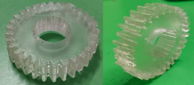
I slowly poured the prepared epoxy mixture into the mold cavity. I made sure to pour carefully from one side of the mold, allowing the air to escape gradually from the opposite side, which helped minimize the formation of air bubbles and ensured a clean, detailed casting. Once the mold was completely filled, I left it undisturbed to cure for 24 hours, allowing the epoxy to harden fully. After the curing process was complete, I carefully removed the final output from the mold and successfully obtained a well-formed spur gear mold with the desired shape and finish.
Reflections and Observations
As part of this week's Moulding and Casting assignment, I completed the process and documented the steps thoroughly. However, I would like to include the following observations and reflections:
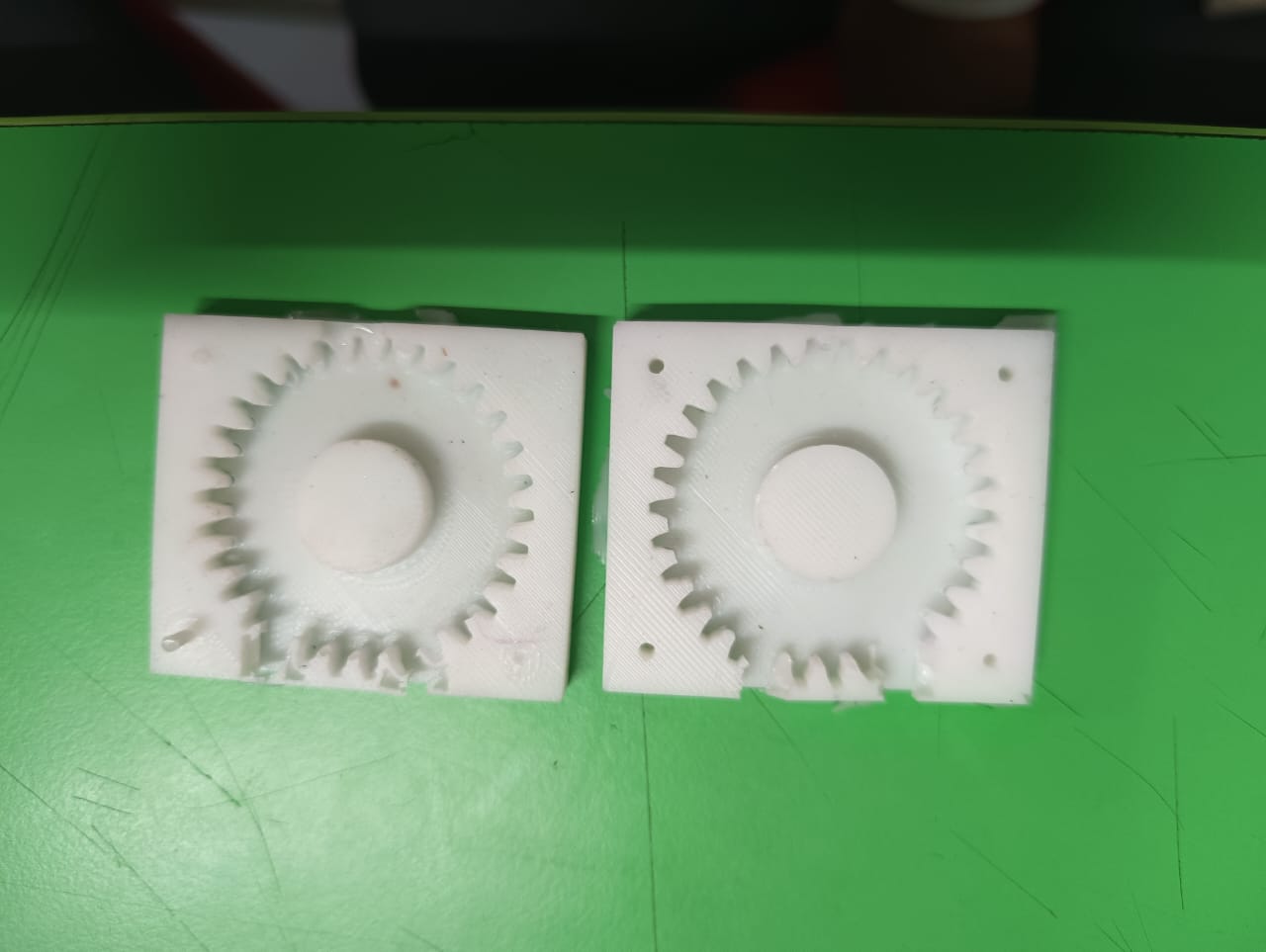
1. Hole Placement and Gear Tooth Defect
During the design phase, I placed a hole in a position that unintentionally interfered with the functional geometry of the part—specifically, the tooth of the gear. This resulted in a defect where the hole partially cut into the gear tooth. This issue highlights the importance of careful consideration when choosing hole locations, especially in areas with critical mechanical features. In future iterations, I will ensure that holes are positioned away from essential design elements to preserve functionality.
2. Surface Finish
One of the objectives of this assignment was to achieve a smooth surface finish on the final cast part. However, the surface did not come out as smooth as intended. This could be due to the quality of the mold, the casting material, or surface preparation techniques. Although the part is usable, I recognize that further attention to detail—such as mold polishing, better material choice, or improving the curing environment—can significantly improve the final appearance and finish. This is a key learning for future casting work.